WO2014013852A1 - 油圧駆動システム - Google Patents
油圧駆動システム Download PDFInfo
- Publication number
- WO2014013852A1 WO2014013852A1 PCT/JP2013/067615 JP2013067615W WO2014013852A1 WO 2014013852 A1 WO2014013852 A1 WO 2014013852A1 JP 2013067615 W JP2013067615 W JP 2013067615W WO 2014013852 A1 WO2014013852 A1 WO 2014013852A1
- Authority
- WO
- WIPO (PCT)
- Prior art keywords
- hydraulic
- pump
- flow path
- bleed
- drive system
- Prior art date
- Legal status (The legal status is an assumption and is not a legal conclusion. Google has not performed a legal analysis and makes no representation as to the accuracy of the status listed.)
- Ceased
Links
Images





Classifications
-
- F—MECHANICAL ENGINEERING; LIGHTING; HEATING; WEAPONS; BLASTING
- F15—FLUID-PRESSURE ACTUATORS; HYDRAULICS OR PNEUMATICS IN GENERAL
- F15B—SYSTEMS ACTING BY MEANS OF FLUIDS IN GENERAL; FLUID-PRESSURE ACTUATORS, e.g. SERVOMOTORS; DETAILS OF FLUID-PRESSURE SYSTEMS, NOT OTHERWISE PROVIDED FOR
- F15B13/00—Details of servomotor systems ; Valves for servomotor systems
- F15B13/02—Fluid distribution or supply devices characterised by their adaptation to the control of servomotors
- F15B13/021—Valves for interconnecting the fluid chambers of an actuator
-
- E—FIXED CONSTRUCTIONS
- E02—HYDRAULIC ENGINEERING; FOUNDATIONS; SOIL SHIFTING
- E02F—DREDGING; SOIL-SHIFTING
- E02F9/00—Component parts of dredgers or soil-shifting machines, not restricted to one of the kinds covered by groups E02F3/00 - E02F7/00
- E02F9/20—Drives; Control devices
- E02F9/2058—Electric or electro-mechanical or mechanical control devices of vehicle sub-units
- E02F9/2095—Control of electric, electro-mechanical or mechanical equipment not otherwise provided for, e.g. ventilators, electro-driven fans
-
- E—FIXED CONSTRUCTIONS
- E02—HYDRAULIC ENGINEERING; FOUNDATIONS; SOIL SHIFTING
- E02F—DREDGING; SOIL-SHIFTING
- E02F9/00—Component parts of dredgers or soil-shifting machines, not restricted to one of the kinds covered by groups E02F3/00 - E02F7/00
- E02F9/20—Drives; Control devices
- E02F9/22—Hydraulic or pneumatic drives
- E02F9/2203—Arrangements for controlling the attitude of actuators, e.g. speed, floating function
-
- E—FIXED CONSTRUCTIONS
- E02—HYDRAULIC ENGINEERING; FOUNDATIONS; SOIL SHIFTING
- E02F—DREDGING; SOIL-SHIFTING
- E02F9/00—Component parts of dredgers or soil-shifting machines, not restricted to one of the kinds covered by groups E02F3/00 - E02F7/00
- E02F9/20—Drives; Control devices
- E02F9/22—Hydraulic or pneumatic drives
- E02F9/2217—Hydraulic or pneumatic drives with energy recovery arrangements, e.g. using accumulators, flywheels
-
- E—FIXED CONSTRUCTIONS
- E02—HYDRAULIC ENGINEERING; FOUNDATIONS; SOIL SHIFTING
- E02F—DREDGING; SOIL-SHIFTING
- E02F9/00—Component parts of dredgers or soil-shifting machines, not restricted to one of the kinds covered by groups E02F3/00 - E02F7/00
- E02F9/20—Drives; Control devices
- E02F9/22—Hydraulic or pneumatic drives
- E02F9/2221—Control of flow rate; Load sensing arrangements
- E02F9/2232—Control of flow rate; Load sensing arrangements using one or more variable displacement pumps
- E02F9/2235—Control of flow rate; Load sensing arrangements using one or more variable displacement pumps including an electronic controller
-
- E—FIXED CONSTRUCTIONS
- E02—HYDRAULIC ENGINEERING; FOUNDATIONS; SOIL SHIFTING
- E02F—DREDGING; SOIL-SHIFTING
- E02F9/00—Component parts of dredgers or soil-shifting machines, not restricted to one of the kinds covered by groups E02F3/00 - E02F7/00
- E02F9/20—Drives; Control devices
- E02F9/22—Hydraulic or pneumatic drives
- E02F9/2278—Hydraulic circuits
- E02F9/2289—Closed circuit
-
- E—FIXED CONSTRUCTIONS
- E02—HYDRAULIC ENGINEERING; FOUNDATIONS; SOIL SHIFTING
- E02F—DREDGING; SOIL-SHIFTING
- E02F9/00—Component parts of dredgers or soil-shifting machines, not restricted to one of the kinds covered by groups E02F3/00 - E02F7/00
- E02F9/20—Drives; Control devices
- E02F9/22—Hydraulic or pneumatic drives
- E02F9/2278—Hydraulic circuits
- E02F9/2292—Systems with two or more pumps
-
- E—FIXED CONSTRUCTIONS
- E02—HYDRAULIC ENGINEERING; FOUNDATIONS; SOIL SHIFTING
- E02F—DREDGING; SOIL-SHIFTING
- E02F9/00—Component parts of dredgers or soil-shifting machines, not restricted to one of the kinds covered by groups E02F3/00 - E02F7/00
- E02F9/20—Drives; Control devices
- E02F9/22—Hydraulic or pneumatic drives
- E02F9/2278—Hydraulic circuits
- E02F9/2296—Systems with a variable displacement pump
-
- F—MECHANICAL ENGINEERING; LIGHTING; HEATING; WEAPONS; BLASTING
- F15—FLUID-PRESSURE ACTUATORS; HYDRAULICS OR PNEUMATICS IN GENERAL
- F15B—SYSTEMS ACTING BY MEANS OF FLUIDS IN GENERAL; FLUID-PRESSURE ACTUATORS, e.g. SERVOMOTORS; DETAILS OF FLUID-PRESSURE SYSTEMS, NOT OTHERWISE PROVIDED FOR
- F15B11/00—Servomotor systems without provision for follow-up action; Circuits therefor
- F15B11/08—Servomotor systems without provision for follow-up action; Circuits therefor with only one servomotor
-
- F—MECHANICAL ENGINEERING; LIGHTING; HEATING; WEAPONS; BLASTING
- F15—FLUID-PRESSURE ACTUATORS; HYDRAULICS OR PNEUMATICS IN GENERAL
- F15B—SYSTEMS ACTING BY MEANS OF FLUIDS IN GENERAL; FLUID-PRESSURE ACTUATORS, e.g. SERVOMOTORS; DETAILS OF FLUID-PRESSURE SYSTEMS, NOT OTHERWISE PROVIDED FOR
- F15B21/00—Common features of fluid actuator systems; Fluid-pressure actuator systems or details thereof, not covered by any other group of this subclass
- F15B21/14—Energy-recuperation means
-
- F—MECHANICAL ENGINEERING; LIGHTING; HEATING; WEAPONS; BLASTING
- F15—FLUID-PRESSURE ACTUATORS; HYDRAULICS OR PNEUMATICS IN GENERAL
- F15B—SYSTEMS ACTING BY MEANS OF FLUIDS IN GENERAL; FLUID-PRESSURE ACTUATORS, e.g. SERVOMOTORS; DETAILS OF FLUID-PRESSURE SYSTEMS, NOT OTHERWISE PROVIDED FOR
- F15B2211/00—Circuits for servomotor systems
- F15B2211/20—Fluid pressure source, e.g. accumulator or variable axial piston pump
- F15B2211/205—Systems with pumps
- F15B2211/2053—Type of pump
- F15B2211/20561—Type of pump reversible
-
- F—MECHANICAL ENGINEERING; LIGHTING; HEATING; WEAPONS; BLASTING
- F15—FLUID-PRESSURE ACTUATORS; HYDRAULICS OR PNEUMATICS IN GENERAL
- F15B—SYSTEMS ACTING BY MEANS OF FLUIDS IN GENERAL; FLUID-PRESSURE ACTUATORS, e.g. SERVOMOTORS; DETAILS OF FLUID-PRESSURE SYSTEMS, NOT OTHERWISE PROVIDED FOR
- F15B2211/00—Circuits for servomotor systems
- F15B2211/20—Fluid pressure source, e.g. accumulator or variable axial piston pump
- F15B2211/205—Systems with pumps
- F15B2211/20576—Systems with pumps with multiple pumps
-
- F—MECHANICAL ENGINEERING; LIGHTING; HEATING; WEAPONS; BLASTING
- F15—FLUID-PRESSURE ACTUATORS; HYDRAULICS OR PNEUMATICS IN GENERAL
- F15B—SYSTEMS ACTING BY MEANS OF FLUIDS IN GENERAL; FLUID-PRESSURE ACTUATORS, e.g. SERVOMOTORS; DETAILS OF FLUID-PRESSURE SYSTEMS, NOT OTHERWISE PROVIDED FOR
- F15B2211/00—Circuits for servomotor systems
- F15B2211/20—Fluid pressure source, e.g. accumulator or variable axial piston pump
- F15B2211/27—Directional control by means of the pressure source
-
- F—MECHANICAL ENGINEERING; LIGHTING; HEATING; WEAPONS; BLASTING
- F15—FLUID-PRESSURE ACTUATORS; HYDRAULICS OR PNEUMATICS IN GENERAL
- F15B—SYSTEMS ACTING BY MEANS OF FLUIDS IN GENERAL; FLUID-PRESSURE ACTUATORS, e.g. SERVOMOTORS; DETAILS OF FLUID-PRESSURE SYSTEMS, NOT OTHERWISE PROVIDED FOR
- F15B2211/00—Circuits for servomotor systems
- F15B2211/30—Directional control
- F15B2211/31—Directional control characterised by the positions of the valve element
- F15B2211/3122—Special positions other than the pump port being connected to working ports or the working ports being connected to the return line
-
- F—MECHANICAL ENGINEERING; LIGHTING; HEATING; WEAPONS; BLASTING
- F15—FLUID-PRESSURE ACTUATORS; HYDRAULICS OR PNEUMATICS IN GENERAL
- F15B—SYSTEMS ACTING BY MEANS OF FLUIDS IN GENERAL; FLUID-PRESSURE ACTUATORS, e.g. SERVOMOTORS; DETAILS OF FLUID-PRESSURE SYSTEMS, NOT OTHERWISE PROVIDED FOR
- F15B2211/00—Circuits for servomotor systems
- F15B2211/30—Directional control
- F15B2211/31—Directional control characterised by the positions of the valve element
- F15B2211/3122—Special positions other than the pump port being connected to working ports or the working ports being connected to the return line
- F15B2211/3133—Regenerative position connecting the working ports or connecting the working ports to the pump, e.g. for high-speed approach stroke
-
- F—MECHANICAL ENGINEERING; LIGHTING; HEATING; WEAPONS; BLASTING
- F15—FLUID-PRESSURE ACTUATORS; HYDRAULICS OR PNEUMATICS IN GENERAL
- F15B—SYSTEMS ACTING BY MEANS OF FLUIDS IN GENERAL; FLUID-PRESSURE ACTUATORS, e.g. SERVOMOTORS; DETAILS OF FLUID-PRESSURE SYSTEMS, NOT OTHERWISE PROVIDED FOR
- F15B2211/00—Circuits for servomotor systems
- F15B2211/30—Directional control
- F15B2211/35—Directional control combined with flow control
- F15B2211/353—Flow control by regulating means in return line, i.e. meter-out control
-
- F—MECHANICAL ENGINEERING; LIGHTING; HEATING; WEAPONS; BLASTING
- F15—FLUID-PRESSURE ACTUATORS; HYDRAULICS OR PNEUMATICS IN GENERAL
- F15B—SYSTEMS ACTING BY MEANS OF FLUIDS IN GENERAL; FLUID-PRESSURE ACTUATORS, e.g. SERVOMOTORS; DETAILS OF FLUID-PRESSURE SYSTEMS, NOT OTHERWISE PROVIDED FOR
- F15B2211/00—Circuits for servomotor systems
- F15B2211/70—Output members, e.g. hydraulic motors or cylinders or control therefor
- F15B2211/705—Output members, e.g. hydraulic motors or cylinders or control therefor characterised by the type of output members or actuators
- F15B2211/7051—Linear output members
- F15B2211/7053—Double-acting output members
-
- F—MECHANICAL ENGINEERING; LIGHTING; HEATING; WEAPONS; BLASTING
- F15—FLUID-PRESSURE ACTUATORS; HYDRAULICS OR PNEUMATICS IN GENERAL
- F15B—SYSTEMS ACTING BY MEANS OF FLUIDS IN GENERAL; FLUID-PRESSURE ACTUATORS, e.g. SERVOMOTORS; DETAILS OF FLUID-PRESSURE SYSTEMS, NOT OTHERWISE PROVIDED FOR
- F15B2211/00—Circuits for servomotor systems
- F15B2211/70—Output members, e.g. hydraulic motors or cylinders or control therefor
- F15B2211/785—Compensation of the difference in flow rate in closed fluid circuits using differential actuators
Definitions
- the present invention relates to a hydraulic drive system.
- a working machine such as a hydraulic shovel or a wheel loader includes a working machine driven by a hydraulic cylinder.
- the hydraulic cylinder is supplied with hydraulic fluid discharged from a hydraulic pump.
- the hydraulic oil is supplied to the hydraulic cylinder via a hydraulic circuit.
- Patent Document 1 proposes a working machine having a hydraulic closed circuit for supplying hydraulic oil to a hydraulic cylinder. Since the hydraulic circuit is a closed circuit, the potential energy of the working machine is regenerated. As a result, it is possible to reduce the fuel consumption of the motor that drives the hydraulic pump.
- a hydraulic shovel has a boom and a boom cylinder.
- the boom is driven by the boom cylinder.
- the boom cylinder has a first chamber and a second chamber.
- the hydraulic fluid is supplied to the first chamber and the hydraulic fluid is discharged from the second chamber, whereby the boom cylinder is extended.
- the hydraulic fluid is discharged from the first chamber, and the boom cylinder is contracted by supplying the hydraulic fluid to the second chamber.
- the hydraulic shovel is required to set the lowering speed of the boom faster than the rising speed of the boom in order to increase the work efficiency. For example, comparing the operation time until the boom cylinder fully extends from the state where the bucket is in contact, if the required time for raising the boom is “1”, the required time for lowering the boom is approximately “0. It is preferably about 7 to 0.8 ".
- the rising speed of the boom is determined by the flow rate of hydraulic fluid supplied to the first chamber. Therefore, the rising speed of the boom is determined by the displacement of the hydraulic pump driven by the drive source.
- the lowering speed of the boom is determined by the flow rate of hydraulic fluid discharged from the first chamber. Thus, the lowering speed of the boom is determined by the meter-out throttle of the control valve arranged between the hydraulic pump and the boom cylinder.
- An object of the present invention is to provide a hydraulic drive system capable of increasing the descent speed of a working machine without using a large capacity hydraulic pump.
- a hydraulic drive system includes a hydraulic pump, a drive source, a work machine, a hydraulic cylinder, a hydraulic fluid channel, and a bleed-off channel.
- the hydraulic pump has a first pump port and a second pump port.
- the hydraulic pump is switchable between a first state and a second state.
- the hydraulic pump sucks the hydraulic fluid from the second pump port and discharges the hydraulic fluid from the first pump port in the first state.
- the hydraulic pump sucks in hydraulic fluid from the first pump port and discharges hydraulic fluid from the second pump port.
- the drive source drives a hydraulic pump.
- the hydraulic cylinder is driven by hydraulic fluid discharged from a hydraulic pump.
- the hydraulic cylinder has a first chamber and a second chamber.
- the hydraulic cylinder discharges the working machine by discharging the hydraulic fluid from the first chamber and supplying the hydraulic fluid to the second chamber.
- the hydraulic cylinder raises the working machine by supplying the hydraulic fluid to the first chamber and discharging the hydraulic fluid from the second chamber.
- the hydraulic fluid channel has a first channel and a second channel.
- the first flow path connects the first pump port and the first chamber.
- the second flow path connects the second pump port and the second chamber.
- the hydraulic fluid flow path constitutes a closed circuit between the hydraulic pump and the hydraulic cylinder.
- the bleed off channel is branched from the first channel. In the bleed-off flow path, part of the hydraulic oil discharged from the first chamber flows when the work machine is lowered.
- a hydraulic drive system is the hydraulic drive system according to the first aspect, further comprising an operation member for operating the operation of the hydraulic cylinder.
- the hydraulic drive system according to a third aspect of the present invention is the hydraulic drive system according to the second aspect, wherein the operation parameter is an operation amount of the operation member.
- the predetermined value is a predetermined operation amount smaller than the maximum operation amount of the operation member.
- the hydraulic drive system according to a fourth aspect of the present invention is the hydraulic drive system according to the third aspect, further comprising a control valve.
- the control valve controls the flow rate of hydraulic fluid flowing from the first flow passage to the bleed off flow passage.
- the opening connected to the bleed-off flow path of the control valve starts to open when the operation amount of the operation member becomes a predetermined operation amount, and increases the opening area according to the increase of the operation amount of the operation member.
- the hydraulic drive system according to a fifth aspect of the present invention is the hydraulic drive system according to the second aspect, wherein the hydraulic pump is a variable displacement pump.
- the operating parameter is the capacity of the hydraulic pump.
- the predetermined value is the maximum displacement of the hydraulic pump.
- the hydraulic drive system according to a sixth aspect of the present invention is the hydraulic drive system according to the fifth aspect, further comprising a control valve.
- the control valve controls the flow rate of hydraulic fluid flowing from the first flow passage to the bleed off flow passage.
- the opening connected to the bleed-off flow path of the control valve starts to open when the displacement of the hydraulic pump reaches the maximum displacement, and increases the opening area according to the increase in the amount of operation of the operation member.
- the hydraulic drive system according to a seventh aspect of the present invention is the hydraulic drive system according to the second aspect, wherein the hydraulic pump is a variable displacement pump.
- the operating parameter is the capacity of the hydraulic pump.
- the predetermined value is a predetermined displacement smaller than the maximum displacement of the hydraulic pump.
- the hydraulic drive system according to an eighth aspect of the present invention is the hydraulic drive system according to the seventh aspect, further comprising a control valve.
- the control valve controls the flow rate of hydraulic fluid flowing from the first flow passage to the bleed off flow passage.
- the opening connected to the bleed-off flow path of the control valve starts to open when the displacement of the hydraulic pump reaches a predetermined displacement, and increases the opening area according to the increase of the operation amount of the operation member.
- the hydraulic drive system is the hydraulic drive system according to the first aspect, further comprising a control valve and a rotational speed sensor.
- the control valve controls the flow rate of hydraulic fluid flowing from the first flow passage to the bleed off flow passage.
- the rotational speed sensor detects the rotational speed of the hydraulic pump or drive source. When the rotational speed of the hydraulic pump or the drive source becomes larger than a predetermined value smaller than the predetermined allowable rotational speed, the opening connected to the bleed-off flow path of the control valve starts to open and is opened according to the increase of the rotational speed. Increase the area.
- a hydraulic drive system is the hydraulic drive system according to any one of the first to ninth aspects, further comprising a charge circuit for replenishing the hydraulic fluid channel with hydraulic fluid.
- the bleed off flow path is connected to the charge circuit.
- the hydraulic drive system according to an eleventh aspect of the present invention is the hydraulic drive system according to any one of the first to ninth aspects, further comprising a hydraulic oil tank for storing hydraulic oil.
- the bleed off channel is connected to the hydraulic oil tank.
- a hydraulic drive system is the hydraulic drive system according to any one of the first to eleventh aspects, further comprising a return flow path.
- the return channel branches from the first channel.
- the return flow path returns a portion of the hydraulic oil discharged from the first chamber to the second flow path.
- the flow rate of the hydraulic oil discharged from the first chamber can be increased without using a large-capacity hydraulic pump. This makes it possible to increase the descent speed of the working machine without using a large-capacity hydraulic pump.
- the operator's intention to quickly lower the work implement is reflected in the operation parameter. Therefore, by controlling the flow of the hydraulic oil to the bleed-off flow path using the operation parameter, the feeling of operation of the work machine can be improved.
- the hydraulic oil discharged from the first chamber Some flow into the bleed off flow path.
- the descent speed of the working machine can be increased even if the amount of suction oil of the hydraulic pump is substantially constant.
- the lowering speed of the work machine can be increased even if the amount of suction oil of the hydraulic pump reaches the maximum capacity.
- the descent speed of the working machine can be increased even if the amount of suction oil of the hydraulic pump is substantially constant.
- the descent speed of the work machine can be increased, and the hydraulic pump or the prime mover can be driven at a rotational speed lower than the allowable rotational speed.
- part of the hydraulic oil discharged from the first chamber when the work machine is lowered is sent to the charge circuit through the bleed off flow path.
- a portion of the hydraulic oil discharged from the first chamber when the work machine is lowered is sent to the hydraulic oil tank through the bleed-off flow path.
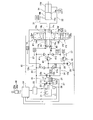
- FIG. 1 is a block diagram showing the configuration of a hydraulic drive system according to a first embodiment.
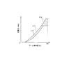
- the figure which shows pump displacement information and bleed-off opening area information.
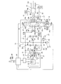
- the block diagram which shows the structure of the hydraulic drive system which concerns on 2nd Embodiment.
- FIG. 1 is a perspective view of a hydraulic shovel 100 equipped with a hydraulic drive system according to a first embodiment of the present invention.
- the hydraulic shovel 100 has a vehicle body 1 and a working machine 2.
- the vehicle body 1 has an upper revolving superstructure 3, a cab 4 and a lower vehicle body 5.
- the upper swing body 3 is mounted on the lower vehicle body 5.
- the upper swing body 3 is provided so as to be swingable with respect to the lower vehicle body 5.
- the upper revolving superstructure 3 accommodates devices such as an engine and a hydraulic pump described later.
- the operator's cab 4 is placed at the front of the upper swing body 3. In the driver's cab 4, an operating device described later is disposed.
- the lower vehicle body 5 has crawler belts 5a and 5b, and the hydraulic shovel 100 travels by rotation of the crawler belts 5a and 5b.
- the working machine 2 is attached to the front of the vehicle body 1 and has a boom 90, an arm 91 and a bucket 92.
- the base end of the boom 90 is swingably attached to the upper swing body 3 via a boom pin 96.
- the proximal end of the arm 91 is pivotably attached to the distal end of the boom 90 via an arm pin 97.
- a bucket 92 is pivotally attached to the tip of the arm 91 via a bucket pin 98.
- the boom 90 is driven by the hydraulic cylinder 14.
- the arm 91 is driven by a hydraulic cylinder 94.
- the bucket 92 is driven by a hydraulic cylinder 95.
- FIG. 2 is a block diagram showing the configuration of the hydraulic drive system.
- the hydraulic drive system is a system for driving the boom 90.
- the hydraulic drive system includes an engine 11, a main pump 10, a hydraulic cylinder 14, a hydraulic fluid flow path 15, a control valve 16, and a pump controller 24.
- the engine 11 drives the main pump 10.
- the engine 11 is an example of the drive source of the present invention.
- the engine 11 is, for example, a diesel engine, and the output of the engine 11 is controlled by adjusting the injection amount of fuel from the fuel injection device 21.
- the adjustment of the fuel injection amount is performed by the fuel injection device 21 being controlled by the engine controller 22.
- the actual rotational speed of the engine 11 is detected by the rotational speed sensor 23, and the detection signal is input to the engine controller 22 and the pump controller 24, respectively.
- the main pump 10 has a first hydraulic pump 12 and a second hydraulic pump 13.
- the first hydraulic pump 12 and the second hydraulic pump 13 are driven by the engine 11 and discharge hydraulic fluid.
- the hydraulic oil discharged from the main pump 10 is supplied to the hydraulic cylinder 14 via the control valve 16.
- the first hydraulic pump 12 is a variable displacement hydraulic pump. By controlling the tilting angle of the first hydraulic pump 12, the displacement of the first hydraulic pump 12 is controlled. The tilt angle of the first hydraulic pump 12 is controlled by the first pump flow control unit 25. The first pump flow rate control unit 25 controls the flow rate of the hydraulic fluid discharged from the first hydraulic pump 12 by controlling the tilt angle of the first hydraulic pump 12 based on the command signal from the pump controller 24. Do.
- the first hydraulic pump 12 is a two-direction discharge hydraulic pump. Specifically, the first hydraulic pump 12 has a first pump port 12a and a second pump port 12b. The first hydraulic pump 12 is switchable between a first discharge state and a second discharge state. In the first discharge state, the first hydraulic pump 12 sucks in hydraulic fluid from the second pump port 12 b and discharges hydraulic fluid from the first pump port 12 a. In the second discharge state, the first hydraulic pump 12 sucks in hydraulic fluid from the first pump port 12a and discharges hydraulic fluid from the second pump port 12b.
- the second hydraulic pump 13 is a variable displacement hydraulic pump.
- the displacement angle of the second hydraulic pump 13 is controlled to control the displacement of the second hydraulic pump 13.
- the tilt angle of the second hydraulic pump 13 is controlled by the second pump flow control unit 26.
- the second pump flow rate control unit 26 controls the flow rate of the hydraulic fluid discharged from the second hydraulic pump 13 by controlling the tilt angle of the second hydraulic pump 13 based on the command signal from the pump controller 24. .
- the second hydraulic pump 13 is a two-direction discharge hydraulic pump. Specifically, the second hydraulic pump 13 has a first pump port 13a and a second pump port 13b. Similar to the first hydraulic pump 12, the second hydraulic pump 13 can be switched between the first discharge state and the second discharge state. In the first discharge state, the second hydraulic pump 13 sucks in hydraulic fluid from the second pump port 13b and discharges hydraulic fluid from the first pump port 13a. In the second discharge state, the second hydraulic pump 13 sucks in hydraulic fluid from the first pump port 13a and discharges hydraulic fluid from the second pump port 13b.
- the hydraulic cylinder 14 is driven by hydraulic fluid discharged from the first hydraulic pump 12 and the second hydraulic pump 13. As described above, the hydraulic cylinder 14 drives the boom 90. The extension of the hydraulic cylinder 14 raises the tip of the boom 90. That is, work implement 2 rises. The contraction of the hydraulic cylinder 14 lowers the tip of the boom 90. That is, the work implement 2 descends. Note that, depending on the mounting state of the hydraulic cylinder 14, the work machine 2 may be lowered by extending the hydraulic cylinder 14. In this case, the work implement 2 is raised by the contraction of the hydraulic cylinder 14.
- the hydraulic cylinder 14 has a cylinder rod 14a and a cylinder tube 14b. The inside of the cylinder tube 14b is divided by the cylinder rod 14a into a first chamber 14c and a second chamber 14d.
- the hydraulic cylinder 14 expands and contracts by switching the supply and discharge of hydraulic fluid to and from the first chamber 14c and the second chamber 14d. Specifically, hydraulic oil is supplied to the first chamber 14c and the hydraulic oil is discharged from the second chamber 14d, whereby the hydraulic cylinder 14 extends. The hydraulic oil is supplied to the second chamber 14d, and the hydraulic cylinder 14 is contracted by discharging the hydraulic oil from the first chamber 14c.
- the pressure receiving area of the first chamber 14c of the cylinder rod 14a is larger than the pressure receiving area of the second chamber 14d of the cylinder rod 14a. Therefore, when the hydraulic cylinder 14 is extended, a larger amount of hydraulic oil is supplied to the first chamber 14c than the hydraulic oil discharged from the second chamber 14d. Further, when the hydraulic cylinder 14 is contracted, a larger amount of hydraulic oil is discharged from the first chamber 14c than the hydraulic oil supplied to the second chamber 14d.
- the hydraulic fluid passage 15 is connected to the first hydraulic pump 12, the second hydraulic pump 13, and the hydraulic cylinder 14.
- the hydraulic fluid channel 15 has a first channel 15a and a second channel 15b.
- the first flow path 15 a connects the first pump port 12 a of the first hydraulic pump 12 and the first chamber 14 c of the hydraulic cylinder 14.
- the first pump port 13a of the second hydraulic pump 13 is connected to the first flow passage 15a.
- the second flow passage 15 b connects the second pump port 12 b of the first hydraulic pump 12 and the second chamber 14 d of the hydraulic cylinder 14.
- the second pump port 13 b of the second hydraulic pump 13 is connected to the hydraulic oil tank 27.
- the first flow passage 15 a has a first cylinder flow passage 31 and a first pump flow passage 33.
- the second flow passage 15 b has a second cylinder flow passage 32 and a second pump flow passage 34.
- the first cylinder channel 31 is connected to the first chamber 14 c of the hydraulic cylinder 14.
- the second cylinder channel 32 is connected to the second chamber 14 d of the hydraulic cylinder 14.
- the first pump flow path 33 supplies hydraulic fluid to the first chamber 14 c of the hydraulic cylinder 14 via the first cylinder flow path 31, or the first chamber of the hydraulic cylinder 14 via the first cylinder flow path 31. It is a flow path for recovering hydraulic oil from 14c.
- the first pump flow path 33 is connected to the first pump port 12 a of the first hydraulic pump 12. Further, the first pump flow path 33 is connected to the first pump port 13 a of the second hydraulic pump 13. Therefore, hydraulic oil from both the first hydraulic pump 12 and the second hydraulic pump 13 is supplied to the first pump flow path 33.
- the second pump flow path 34 supplies hydraulic fluid to the second chamber 14 d of the hydraulic cylinder 14 via the second cylinder flow path 32, or the second chamber of the hydraulic cylinder 14 via the second cylinder flow path 32. It is a flow path for recovering hydraulic oil from 14 d.
- the second pump flow path 34 is connected to the second pump port 12 b of the first hydraulic pump 12.
- the second pump port 13 b of the second hydraulic pump 13 is connected to the hydraulic oil tank 27. Therefore, the hydraulic fluid from the first hydraulic pump 12 is supplied to the second pump flow path 34.
- the hydraulic fluid passage 15 forms a closed circuit between the main pump 10 and the hydraulic cylinder 14 by the first passage 15 a and the second passage 15 b.
- the hydraulic drive system further comprises a charge pump 28.
- the charge pump 28 is a hydraulic pump for replenishing the first flow path 15a or the second flow path 15b with hydraulic fluid.
- the charge pump 28 discharges hydraulic oil by being driven by the engine 11.
- the charge pump 28 is a fixed displacement hydraulic pump.
- the hydraulic fluid passage 15 further includes a charge circuit 35.
- the charge circuit 35 is connected to the first pump flow path 33 via the check valve 41a.
- the check valve 41 a is opened when the hydraulic pressure of the first pump flow path 33 becomes lower than the hydraulic pressure of the charge circuit 35.
- the charge circuit 35 is connected to the second pump flow path 34 via the check valve 41 b.
- the check valve 41 b is opened when the hydraulic pressure of the second pump flow path 34 becomes lower than the hydraulic pressure of the charge circuit 35.
- the charge circuit 35 is connected to the hydraulic oil tank 27 via the charge relief valve 42.
- the charge relief valve 42 maintains the hydraulic pressure of the charge circuit 35 at a predetermined charge pressure.
- the hydraulic fluid channel 15 further has a relief channel 36.
- the relief flow passage 36 is connected to the first pump flow passage 33 via the check valve 41 c.
- the check valve 41 c is opened when the hydraulic pressure of the first pump flow path 33 becomes higher than the hydraulic pressure of the relief flow path 36.
- the relief flow passage 36 is connected to the second pump flow passage 34 via the check valve 41 d.
- the check valve 41 d is opened when the hydraulic pressure of the second pump flow path 34 becomes higher than the hydraulic pressure of the relief flow path 36.
- the relief flow passage 36 is connected to the charge circuit 35 via the relief valve 43.
- the relief valve 43 maintains the pressure in the relief flow passage 36 below a predetermined relief pressure. As a result, the hydraulic pressure of the first pump flow path 33 and the second pump flow path 34 is maintained at or below the predetermined relief pressure.
- the hydraulic drive system has a bleed off flow path 37.
- the bleed off flow path 37 is connected to the charge circuit 35. Excess bleed fluid from the first pump flow path 33 and the second pump flow path 34 is supplied to the bleed-off flow path 37 at the time of micro speed control of the hydraulic cylinder 14. Further, when the work implement 2 is lowered, a part of the hydraulic oil discharged from the first chamber 14 c flows into the bleed off flow path 37.
- the minute speed control of the hydraulic cylinder 14 and the control at the time of lowering of the work machine 2 will be described in detail later.
- the control valve 16 is an electromagnetic control valve controlled based on a command signal from the pump controller 24.
- the control valve 16 controls the flow rate of hydraulic fluid supplied to the hydraulic cylinder 14 based on a command signal from the pump controller 24.
- the control valve 16 is disposed between the main pump 10 and the hydraulic cylinder 14 in the hydraulic fluid passage 15. When extending the hydraulic cylinder 14 by micro-speed control of the hydraulic cylinder 14 described later, the control valve 16 controls the flow rate of the hydraulic oil supplied from the first pump flow path 33 to the hydraulic cylinder 14 and the control valve 16 from the first pump flow path 33 The flow rate of the hydraulic oil supplied to the bleed off flow path 37 is controlled.
- control valve 16 controls the flow rate of the hydraulic oil supplied from the second pump flow path 34 to the hydraulic cylinder 14 and the bleed off flow path from the second pump flow path 34 Control the flow rate of the hydraulic oil supplied to 37.
- the control valve 16 may be a hydraulic control valve controlled by pilot hydraulic pressure.
- an electromagnetic proportional pressure reducing valve is disposed between the pump controller 24 and the hydraulic pressure control valve.
- the electromagnetic proportional pressure reducing valve is controlled by a command signal from the pump controller 24.
- the electromagnetic proportional pressure reducing valve supplies a pilot hydraulic pressure corresponding to the command signal to the hydraulic pressure control valve.
- the hydraulic control valve is switch-controlled by the pilot hydraulic pressure.
- the electromagnetic proportional pressure reducing valve reduces the hydraulic oil discharged by the pilot pump to generate a pilot hydraulic pressure.
- hydraulic oil discharged from the charge pump 28 may be used.
- the control valve 16 has a first pump port 16a, a first cylinder port 16b, a first bleed off port 16c, and a first bypass port 16d.
- the first pump port 16 a is connected to the first pump flow path 33 via the first direction control unit 44.
- the first direction control unit 44 is a check valve that regulates the flow of hydraulic oil in one direction.
- the first cylinder port 16 b is connected to the first cylinder channel 31.
- the first bleed off port 16 c is connected to the bleed off flow path 37.
- the control valve 16 further includes a second pump port 16e, a second cylinder port 16f, a second bleed off port 16g, and a second bypass port 16h.
- the second pump port 16 e is connected to the second pump flow path 34 via the second direction control unit 45.
- the second direction control unit 45 is a check valve that regulates the flow of hydraulic oil in one direction.
- the second cylinder port 16 f is connected to the second cylinder channel 32.
- the second bleed off port 16 g is connected to the bleed off channel 37.
- the control valve 16 is switchable between a first position state P1, a second position state P2, a neutral position state Pn and a third position state P3.
- the control valve 16 brings the first pump port 16a into communication with the first cylinder port 16b, and brings the second cylinder port 16f into communication with the second bypass port 16h. Therefore, in the first position state P1, the control valve 16 connects the first pump flow path 33 to the first cylinder flow path 31 via the first direction control unit 44, and the second cylinder flow path 32 And the second direction control unit 45 without being connected to the second pump flow path 34.
- the first bypass port 16d, the first bleed-off port 16c, the second pump port 16e, and the second bleed-off port 16g are for any port. Is also blocked.
- the hydraulic cylinder 14 When the hydraulic cylinder 14 is extended, the first hydraulic pump 12 and the second hydraulic pump 13 are driven in the first discharge state, and the control valve 16 is set to the first position state P1.
- the hydraulic fluid discharged from the first pump port 12 a of the first hydraulic pump 12 and the first pump port 13 a of the second hydraulic pump 13 is the first pump flow path 33, the first direction control unit 44, It is supplied to the first chamber 14 c of the hydraulic cylinder 14 through the first cylinder channel 31.
- the hydraulic oil in the second chamber 14 d of the hydraulic cylinder 14 is recovered to the second pump port 12 b of the first hydraulic pump 12 through the second cylinder channel 32 and the second pump channel 34. Thereby, the hydraulic cylinder 14 is extended.
- the control valve 16 brings the second pump port 16e into communication with the second cylinder port 16f, and brings the first cylinder port 16b into communication with the first bypass port 16d. Therefore, in the second position state P2, the control valve 16 connects the first cylinder flow passage 31 to the first pump flow passage 33 without passing through the first direction control unit 44, and the second pump flow passage 34. Is connected to the second cylinder flow passage 32 via the second direction control unit 45.
- the first pump port 16a, the first bleed-off port 16c, the second bypass port 16h, and the second bleed-off port 16g are for any port. Is also blocked.
- the control valve 16 brings the first bypass port 16d into communication with the first bleed-off port 16c, and brings the second bypass port 16h into communication with the second bleed-off port 16g. Therefore, in the neutral position state Pn, the control valve 16 connects the first pump flow path 33 to the bleed-off flow path 37 without passing through the first direction control unit 44, and the second pump flow path 34 It is connected to the bleed off channel 37 without passing through the second direction control unit 45.
- the first pump port 16a, the first cylinder port 16b, the second pump port 16e, and the second cylinder port 16f are for any port. Is also blocked.
- the control valve 16 causes the second pump port 16e to communicate with the second cylinder port 16f, and causes the first cylinder port 16b to communicate with the first bypass port 16d. Therefore, in the third position state P3, the control valve 16 connects the first cylinder flow passage 31 to the first pump flow passage 33 without the intervention of the first direction control unit 44, and the second pump flow passage 34. Is connected to the second cylinder flow passage 32 via the second direction control unit 45. Furthermore, in the third position state P3, the control valve 16 causes the first bleed off port 16c to communicate with the first cylinder port 16b via the throttle 17. Therefore, in the third position state P3, the control valve 16 connects the first cylinder channel 31 to the bleed-off channel 37 via the throttle 17.
- the bleed-off flow channel 37 is connected to the first flow channel 15a so as to branch from the first flow channel 15a.
- the control valve 16 is in the third position state P3, the first pump port 16a, the second bypass port 16h, and the second bleed off port 16g are disconnected from any of the ports.
- the control valve 16 can be set to any position between the first position P1 and the neutral position Pn. Thereby, the control valve 16 controls the flow rate of the hydraulic oil supplied from the first pump flow path 33 to the first cylinder flow path 31 via the first direction control unit 44 and the bleed off flow from the first pump flow path 33.
- the flow rate of the hydraulic oil supplied to the passage 37 can be controlled. That is, the control valve 16 controls the flow rate of hydraulic oil supplied from the first hydraulic pump 12 and the second hydraulic pump 13 to the first chamber 14 c of the hydraulic cylinder 14 and bleeds from the first hydraulic pump 12 and the second hydraulic pump 13.
- the flow rate of the hydraulic oil supplied to the off flow path 37 can be controlled.
- the control valve 16 can be set to any position between the second position P2 and the neutral position Pn. Thereby, the control valve 16 controls the flow rate of the hydraulic oil supplied from the second pump flow path 34 to the second cylinder flow path 32 via the second direction control unit 45 and the bleed off flow from the second pump flow path 34.
- the flow rate of the hydraulic oil supplied to the passage 37 can be controlled. That is, the control valve 16 controls the flow rate of the hydraulic oil supplied from the first hydraulic pump 12 to the second chamber 14 d of the hydraulic cylinder 14 and the flow rate of the hydraulic oil supplied from the first hydraulic pump 12 to the bleed-off flow path 37 And can be controlled.
- the control valve 16 can be set to any position between the second position P2 and the third position P3. Thus, the control valve 16 can control the flow rate of the hydraulic oil bled off from the first cylinder flow path 31 to the bleed off flow path 37.
- the opening between the first cylinder port 16b and the first bypass port 16d is fully open. Further, the opening between the second pump port 16e and the second cylinder port 16f is fully open.
- the hydraulic drive system further comprises an operating device 46.
- the operating device 46 includes an operating member 46 a and an operation detection unit 46 b.
- the operating member 46 a is a member for operating the operation of the hydraulic cylinder 14.
- the operation member 46a is a boom operation lever.
- the operating member 46 a can be operated in two directions, a direction in which the hydraulic cylinder 14 is extended from the neutral position, and a direction in which the hydraulic cylinder 14 is contracted.
- the operation detection unit 46 b detects an operation amount of the operation member 46 a (hereinafter referred to as “boom operation amount”) and an operation direction.
- the operation detection unit 46 b is, for example, a sensor that detects the position of the operation member 46 a. When the operation member 46 is in the neutral position, the boom operation amount is zero.
- a detection signal indicating the boom operation amount and the operation direction is input from the operation detection unit 46 b to the pump controller 24.
- the pump controller 24 calculates a target flow rate of the hydraulic oil supplied to the hydraulic cylinder 14 according to the boom operation amount.
- the engine controller 22 controls the fuel injection device 21 to control the output of the engine 11.
- the engine controller 22 maps and stores engine output torque characteristics that are set based on the set target engine rotational speed and work mode.
- the engine output torque characteristic indicates the relationship between the output torque of the engine 11 and the rotational speed.
- the engine controller 22 controls the output of the engine 11 based on the engine output torque characteristic.
- the pump controller 24 controls the flow rate of the hydraulic oil supplied to the hydraulic cylinder 14 by the control valve 16 when the target flow rate set by the operation member 46 a is within the predetermined range. Further, when the target flow rate set by the operating member 46 a is larger than the predetermined range, the pump controller 24 controls the flow rate of the hydraulic oil supplied to the hydraulic cylinder 14 by the first pump flow rate control unit 25 and the second pump flow rate control unit 26. Control. Specifically, the pump controller 24 controls the flow rate of the hydraulic oil supplied to the hydraulic cylinder 14 by the control valve 16 when the boom operation amount is within the predetermined slow operation range.
- the pump controller 24 When the hydraulic cylinder 14 is extended, the pump controller 24 is supplied to the hydraulic cylinder 14 by the first pump flow control unit 25 and the second pump flow control unit 26 when the boom operation amount is larger than the predetermined low speed operation range. Control the flow rate of hydraulic fluid. When the hydraulic cylinder 14 is contracted, the pump controller 24 controls the flow rate of the hydraulic oil supplied to the hydraulic cylinder 14 by the first pump flow control unit 25 when the boom operation amount is larger than the predetermined slow speed operation range.
- the predetermined low speed operation range is an operation range of the operation member 46a corresponding to the above-described predetermined range of the target flow rate.
- the “predetermined slow speed operation range” is an operation range of the operation member 46 a when the hydraulic cylinder 14 is controlled at a minute speed. That is, the "predetermined low speed operation range” is an operation range of the operation member 46a that requires control of a minute flow rate below the minimum controllable flow rate of the discharge flow rate of the hydraulic pump.
- the predetermined low speed operation range is a range of about 15 to 20% of the maximum operation amount in the extension direction of the hydraulic cylinder 14 from the neutral position.
- the predetermined low speed operation range is a range of about 15 to 20% of the maximum operation amount in the contraction direction of the hydraulic cylinder 14 from the neutral position.
- control of the hydraulic cylinder 14 when the boom operation amount is within the predetermined slow speed operation range will be referred to as “micro speed control”.
- control of the hydraulic cylinder 14 when the boom operation amount is larger than the predetermined slow speed operation range is referred to as "normal control”. In the following description, control when extending the hydraulic cylinder 14 will be described.
- the pump controller 24 controls the flow rate of the hydraulic fluid to the hydraulic cylinder 14 by controlling the control valve 16.
- the pump controller 24 sets the control valve 16 to the neutral position state Pn. For this reason, when the boom operation amount is smaller than the predetermined slow speed operation range, the opening area between the first pump flow passage 33 and the first cylinder flow passage 31 is zero. Further, the control valve 16 is controlled such that the opening area between the first pump flow path 33 and the bleed-off flow path 37 decreases as the boom operation amount increases.
- the pump controller 24 makes the tilt angle of the first hydraulic pump 12 and the tilt angle of the second hydraulic pump 13 zero.
- the pump controller 24 controls the control valve 16 between the first position state P1 and the neutral position state Pn. Specifically, when the boom operation amount is within the predetermined low speed operation range, the opening area between the first pump flow passage 33 and the first cylinder flow passage 31 increases as the boom operation amount increases. , The control valve 16 is controlled. Further, the control valve 16 is controlled such that the opening area between the first pump flow path 33 and the bleed-off flow path 37 decreases as the boom operation amount increases.
- control valve is controlled so that the opening area between the first pump flow path 33 and the bleed-off flow path 37 becomes zero when the boom operation amount is the maximum operation amount in the slow speed operation range (see b2 in FIG. 3). 16 is controlled. Furthermore, when the boom operation amount is within the predetermined low speed operation range, the total discharge flow rate of the first hydraulic pump 12 and the second hydraulic pump 13 is maintained at the predetermined discharge flow rate. Specifically, the first hydraulic pump 12 and the second hydraulic pump 13 have a predetermined tilt so that the total discharge flow rate of the first hydraulic pump 12 and the second hydraulic pump 13 is maintained at a predetermined discharge flow rate. Maintained at the corners. The predetermined discharge flow rate is larger than the target flow rate corresponding to the boom operation amount.
- the hydraulic oil from the first hydraulic pump 12 and the second hydraulic pump 13 is supplied separately to the hydraulic cylinder 14 and the bleed off channel 37. That is, among the hydraulic oil from the first hydraulic pump 12 and the second hydraulic pump 13, the hydraulic oil of the flow rate necessary for micro-speed control of the hydraulic cylinder 14 passes through the first cylinder channel 31 to the hydraulic cylinder 14. Supplied. In addition, excess hydraulic oil is sent to the charge circuit 35 via the bleed-off flow path 37. Excess hydraulic oil is returned from the charge circuit 35 to the first pump flow path 33 or the second pump flow path 34 or is sent to the hydraulic oil tank 27 via the charge relief valve 42.
- the pump controller 24 controls the flow rate of hydraulic fluid to the hydraulic cylinder 14 by controlling the first pump flow control unit 25 and the second pump flow control unit 26. Specifically, the pump controller 24 sets the control valve 16 to the first position state P1 when the boom operation amount is larger than the predetermined slow speed operation range. Therefore, the opening area between the first pump flow path 33 and the bleed off flow path 37 is made zero. That is, the space between the first pump flow path 33 and the bleed off flow path 37 is closed.
- the pump controller 24 fully opens the opening area between the first pump flow path 33 and the first cylinder flow path 31 when the boom operation amount is larger than the predetermined slow speed operation range. Further, when the boom operation amount is larger than the predetermined low speed operation range, the first pump flow control is performed so that the total discharge flow rate of the first hydraulic pump 12 and the second hydraulic pump 13 becomes the target flow rate corresponding to the boom operation amount.
- the unit 25 and the second pump flow control unit 26 are controlled.
- the pump controller 24 controls the absorption torque of the first hydraulic pump 12 and the absorption torque of the second hydraulic pump 13 based on the pump absorption torque characteristic.
- the discharge flow rate and the discharge flow rate of the second hydraulic pump 13 are controlled.
- the pump absorption torque characteristic indicates the relationship between the pump absorption torque and the engine rotational speed.
- the pump absorption torque characteristic is set in advance based on the operation mode and the operating condition, and stored in the pump controller 24.
- the control of the hydraulic cylinder 14 when the hydraulic cylinder 14 contracts includes high speed control in addition to the above-described micro speed control and normal control.
- the microspeed control when the hydraulic cylinder 14 contracts is similar to the microspeed control when the hydraulic cylinder 14 described above extends.
- hydraulic oil from the first hydraulic pump 12 is supplied to the hydraulic cylinder 14 without supplying hydraulic oil from the second hydraulic pump 13. Therefore, a part of the hydraulic fluid discharged from the first hydraulic pump 12 is supplied to the hydraulic cylinder 14 via the second pump channel 34 and the second cylinder channel 32.
- surplus hydraulic oil among the hydraulic oil discharged from the first hydraulic pump 12 is sent to the charge circuit 35 via the bleed-off flow path 37.
- the pump controller 24 controls the control valve 16 to supply the flow rate of the hydraulic oil supplied from the first hydraulic pump 12 to the hydraulic cylinder 14 and the first hydraulic pump 12 to the bleed off flow path 37. Control the flow rate of hydraulic fluid.
- the normal control when the hydraulic cylinder 14 is contracted is similar to the normal control when the hydraulic cylinder 14 described above is extended. However, at the time of normal control when the hydraulic cylinder 14 is contracted, the hydraulic oil discharged from the first hydraulic pump 12 is supplied to the hydraulic cylinder 14 via the second pump flow path 34 and the second cylinder flow path 32. At this time, the pump controller 24 controls the first pump flow control unit 25 to control the discharge flow rate of the first hydraulic pump 12.
- FIG. 3 is a diagram showing pump displacement information L1 and bleed-off opening area information L2.
- the pump displacement information L1 defines the relationship between the boom operation amount and the displacement of the first hydraulic pump 12. In the pump displacement information L1, the pump displacement increases as the boom operation amount increases. When the boom operation amount is a predetermined value A1, the capacity of the first hydraulic pump 12 is the maximum capacity Dmax.
- the bleed-off opening area information L2 defines the relationship between the boom operation amount in the high speed control and the bleed-off opening area.
- the bleed-off opening area is the area of the opening connected to the bleed-off channel 37 in the control valve 16.
- L3 has shown bleed-off opening area information in micro speed control mentioned above. In high speed control, the bleed-off opening area is controlled by setting the control valve 16 to a position state between the second position state P2 and the third position state P3.
- the bleed-off opening area information L2 when the boom operation amount is smaller than the predetermined value A1, the bleed-off opening area is zero. That is, when the boom operation amount is smaller than the predetermined value A1, the space between the bleed off flow path 37 and the first flow path 15a is closed. Therefore, when the boom operation amount is smaller than the predetermined value A1 when the work machine 2 is lowered, the entire amount of hydraulic oil discharged from the first chamber 14c is transmitted to the first hydraulic pump 12 via the first flow passage 15a. It is returned to the first pump port 12 a and the first pump port 13 a of the second hydraulic pump 13. When the boom operation amount is equal to or more than the predetermined value A1, the bleed-off opening area is increased as the boom operation amount is increased.
- the opening of the control valve 16 connected to the bleed-off channel 37 starts to open when the boom operation amount reaches the predetermined value A1. That is, the opening connected to the bleed-off flow path 37 of the control valve 16 starts to open when the displacement of the first hydraulic pump 12 reaches the maximum displacement Dmax. And a bleed-off opening area increases according to the increase in the amount of boom operation.
- the boom operation amount is equal to or more than the predetermined value A1 when the work machine 2 is lowered, a part of the hydraulic oil discharged from the first chamber 14c flows into the bleed off flow path 37. Therefore, the flow rate of the hydraulic oil returned to the first pump port 12a, 13a is smaller than the total amount of hydraulic oil discharged from the first chamber 14c.
- a sensor for detecting the tilt angle of the first hydraulic pump 12 is provided according to the boom operation amount detected by the operation detection unit 46 b, and the pump controller 24 controls the tilt angle of the first hydraulic pump 12 detected by the sensor. Based on the determination, it may be determined whether the displacement of the first hydraulic pump 12 has reached the maximum displacement Dmax.
- the ratio of the pressure receiving area of the first chamber 14c of the cylinder rod 14a to the pressure receiving area of the second chamber 14d is 2: 1.
- the hydraulic fluid is supplied to the second chamber 14 d in order to contract the hydraulic cylinder 14.
- the inflow flow rate from the second cylinder flow path 32 to the second chamber 14 d is “1.0”
- the discharge flow rate from the first chamber 14 c to the first cylinder flow path 31 is “2.0”.
- the pump controller 24 sets the control valve 16 between the second position state and the third position state P3 so that the bleed-off opening area has a value corresponding to the boom operation amount.
- the hydraulic oil of “0.4” among the hydraulic oil of the first cylinder channel 31 is sent to the bleed-off channel 37.
- the amount of hydraulic fluid sent to the bleed-off channel 37 is determined by the bleed-off opening area.
- the remaining "1.6" hydraulic oil is sent to the first pump flow path 33. Since the first hydraulic pump 12 and the second hydraulic pump 13 are set to the same capacity, "0.8" of the hydraulic oil supplied to the first pump flow path 33 corresponds to the first hydraulic pump 12 and the second hydraulic pump 12, respectively. Return to the hydraulic pump 13.
- a total of “1.0” of the “0.8” hydraulic oil discharged from the first hydraulic pump 12 and the “0.2” hydraulic oil from the charge circuit 35 Hydraulic oil is supplied.
- the hydraulic drive system according to the present embodiment has the following features.
- FIG. 4 shows the relationship L11 between the flow rate of the hydraulic fluid discharged from the first chamber 14c when the work machine 2 descends and the boom operation amount, and the flow rate of the hydraulic fluid supplied to the first chamber 14c when the work machine 2 rises It is a figure which shows relationship L12 of and boom operation amount.
- the flow rate of the hydraulic oil discharged from the first chamber 14 c when the work machine 2 descends is larger than the flow rate of the hydraulic oil supplied to the first chamber 14 c when the work machine 2 rises. Thereby, the descent speed of the working machine 2 can be made larger than the elevating speed.
- a hatched portion ⁇ Q in FIG. 4 is an increment of the discharge flow rate from the first chamber 14c, which is necessary to make the lowering speed of the work implement 2 larger than the rising speed.
- the hydraulic oil corresponding to this increment is sent to the bleed off channel 37. For this reason, the descent speed of the work machine 2 can be increased without increasing the capacities of the first hydraulic pump 12 and the second hydraulic pump 13.
- the bleed off opening area is determined according to the boom operation amount.
- the boom operation amount reflects the intention of the operator to lower the work implement 2 quickly. Therefore, by controlling the flow of hydraulic fluid to the bleed-off flow path 37 using the boom operation amount, the feeling of operation of the work machine 2 can be improved.
- the predetermined operation amount A1 is a boom operation amount at which the displacement of the first hydraulic pump 12 is the maximum displacement Dmax. Accordingly, when the displacement of the first hydraulic pump 12 reaches the maximum displacement Dmax, the pump controller 24 starts to open the opening connected to the bleed-off flow path 37 of the control valve 16, and thereafter, according to the increase of the boom operation amount. The bleed off opening area of the control valve 16 is increased. Thereby, even if the suction oil amount of the first hydraulic pump 12 reaches the maximum displacement Dmax, the descent speed of the work implement 2 can be increased.
- FIG. 1 A hydraulic drive system according to a second embodiment of the present invention is shown in FIG.
- the control valve 16 has, in the third position state P3, the return flow passage 18 that causes the first cylinder port 16b and the second cylinder port 16f to communicate with each other.
- the return flow passage 18 branches from the first flow passage 15a, and a portion of the hydraulic oil discharged from the first chamber 14c is transferred to the second flow passage 15b.
- a check valve 19 and a throttle 20 are disposed in the return flow path 18.
- the check valve 19 allows the flow of hydraulic oil from the first flow passage 15a to the second flow passage 15b.
- the check valve 19 prohibits the flow of hydraulic oil from the second flow passage 15b to the first flow passage 15a.
- the control valve 16 causes the first bleed-off port 16c and the first cylinder port 16b to communicate with each other via the throttle 17 in the third position state P3, and also allows the first cylinder port 16b and the second cylinder port 16f to communicate with each other. Are communicated through the check valve 19 and the throttle 20. That is, in the third position state P3, the control valve 16 connects the first cylinder flow path 31 to the bleed-off flow path 37 via the throttle 17, and at the same time the check valve 19 and the throttle 20 are used. It connects to the 2nd cylinder channel 32 via vias.
- the other configuration of the hydraulic drive system according to the second embodiment is the same as the configuration of the hydraulic drive system according to the first embodiment.
- the inflow rate from the second cylinder flow path 32 to the second chamber 14 d is, for example, “1.0” when the work implement 2 descends
- the discharge flow rate from the first chamber 14 c to the first cylinder flow path 31 is It is "2.0”.
- the pump controller 24 sets the control valve 16 between the second position state and the third position state P3 so that the bleed-off opening area has a value corresponding to the boom operation amount.
- “0.2” of the hydraulic oil in the first cylinder channel 31 is sent to the bleed-off channel 37.
- the hydraulic oil of “0.2” among the hydraulic oil of the first cylinder flow passage 31 is sent to the second cylinder flow passage 32 through the return flow passage 18.
- the hydraulic oil of “0.2” sent to the bleed-off flow path 37 is sent to the hydraulic oil tank 27 via the charge circuit 35 and the charge relief valve 42.
- the remaining "1.6" hydraulic oil of the first cylinder flow path 31 is sent to the first pump flow path 33, and each "0.8” of hydraulic oil is transferred to the first hydraulic pump 12 and the second hydraulic pump 13 Return to The hydraulic oil of “0.8” is discharged from the first hydraulic pump 12 to the second pump flow path 34, and merges with the hydraulic oil of “0.2” from the return flow path 18. Then, a total of “1.0” of hydraulic oil is supplied to the second chamber 14 d of the hydraulic cylinder 14.
- the same effect as the hydraulic drive system according to the first embodiment can be obtained.
- the hydraulic drive system according to the second embodiment when the work machine 2 is lowered, a part of the hydraulic oil discharged from the first chamber 14c is sent to the bleed off flow path 37, and the first chamber 14c. The other part of the hydraulic oil discharged from the fuel tank is returned to the second flow passage 15b through the return flow passage 18. Thereby, the descent speed of work implement 2 can be further increased.
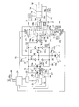
- FIG. 3 A hydraulic drive system according to a third embodiment of the present invention is shown in FIG.
- the hydraulic drive system according to the third embodiment includes a bleed off flow path 38.
- the control valve 16 has a third bleed off port 16i.
- the bleed off flow path 38 is connected to the third bleed off port 16i and the hydraulic fluid tank 27.
- the control valve 16 has a return flow passage 18 communicating the first cylinder port 16b with the second cylinder port 16f in the third position state P3.
- the return flow passage 18 branches from the first flow passage 15a, and a portion of the hydraulic oil discharged from the first chamber 14c is transferred to the second flow passage 15b.
- a check valve 19 and a throttle 20 are disposed in the return flow path 18.
- the control valve 16 causes the first cylinder port 16b and the third bleed off port 16i to communicate with each other via the throttles 20 and 17 in the third position state P3, and the first cylinder port 16b and the second cylinder port. 16f are communicated with each other through the throttle 20 and the check valve 19. That is, in the third position state P3, the control valve 16 connects the first cylinder channel 31 to the bleed-off channel 38 via the throttles 20 and 17, and at the same time the throttle 20 and check valve It is connected to the second cylinder flow path 32 via 19.
- the other configuration of the hydraulic drive system according to the third embodiment is the same as the configuration of the hydraulic drive system according to the first embodiment.
- the inflow rate from the second cylinder flow path 32 to the second chamber 14 d is, for example, “1.0” when the work implement 2 descends
- the discharge flow rate from the first chamber 14 c to the first cylinder flow path 31 is It is "2.0”.
- the pump controller 24 sets the control valve 16 between the second position state and the third position state P3 so that the bleed-off opening area has a value corresponding to the boom operation amount.
- the hydraulic oil of “0.2” among the hydraulic oil of the first cylinder channel 31 is sent to the hydraulic oil tank 27 through the bleed-off channel 38.
- FIG. 4 A hydraulic drive system according to a fourth embodiment of the present invention is shown in FIG.
- the control valve 16 causes the first cylinder port 16b and the third bleed off port 16i to communicate with each other via the check valve 19 and the throttle 17 in the third position state P3.
- the first cylinder port 16 b and the second cylinder port 16 f are communicated via the check valve 19 and the throttle 20. That is, in the third position state P 3, the control valve 16 connects the first cylinder flow path 31 to the bleed-off flow path 38 via the check valve 19 and the throttle 17 and the first cylinder flow path 31 to the check valve 19. And the throttle 20 to the second cylinder channel 32.
- the other configuration of the hydraulic drive system according to the fourth embodiment and the flow of hydraulic oil at the time of high speed control are the same as the configuration of the hydraulic drive system according to the third embodiment, and thus the description thereof will be omitted. Also in the hydraulic drive system according to the fourth embodiment, the same effects as those of the hydraulic drive system according to the third embodiment can be obtained.
- FIG. 5 A hydraulic drive system according to a fifth embodiment of the present invention is shown in FIG.
- the second hydraulic pump 13 is omitted in the hydraulic drive system of the first embodiment. Therefore, the main pump 10 is comprised by one hydraulic pump (1st hydraulic pump 12).
- the hydraulic drive system according to the fifth embodiment includes the shuttle valve 51.
- the shuttle valve 51 has a first input port 51a, a second input port 51b, a drain port 51c, a first pressure receiving portion 51d, and a second pressure receiving portion 51e.
- the first input port 51a is connected to the first flow path 15a.
- the second input port 51 b is connected to the second flow path 15 b.
- the first input port 51 a is connected to the first pump flow path 33.
- the second input port 51 b is connected to the second pump flow path 34.
- the drain port 51 c is connected to the drain passage 52.
- the drain flow path 52 is connected to the charge circuit 35 via the bleed off flow path 37.
- the first pressure receiving portion 51 d is connected to the first flow passage 15 a via the first pilot flow passage 53.
- the hydraulic pressure of the first flow passage 15a is applied to the first pressure receiving portion 51d.
- a throttle 54 is disposed in the first pilot flow channel 53.
- the second pressure receiving portion 51 e is connected to the second flow passage 15 b via the second pilot flow passage 55. Accordingly, the hydraulic pressure of the second flow passage 15b is applied to the second pressure receiving portion 51e.
- a throttle 56 is disposed in the second pilot flow channel 55.
- the shuttle valve 51 is switched to the first position state Q1, the second position state Q2, and the neutral position state Qn according to the hydraulic pressure of the first flow path 15a and the hydraulic pressure of the second flow path 15b.
- the shuttle valve 51 brings the second input port 51b into communication with the drain port 51c in the first position state Q1.
- the second flow passage 15 b is connected to the drain flow passage 52.
- the shuttle valve 51 causes the first input port 51a and the drain port 51c to communicate with each other in the second position state Q2.
- the first flow path 15 a is connected to the drain flow path 52.
- the shuttle valve 51 closes between the first input port 51a, the second input port 51b, and the drain port 51c in the neutral position state Qn.
- the shuttle valve 51 has a spool 57, a first elastic member 58, and a second elastic member 59.
- the first elastic member 58 presses the spool 57 from the side of the first pressure receiving portion 51 d toward the side of the second pressure receiving portion 51 e.
- the second elastic member 59 presses the spool 57 from the side of the second pressure receiving portion 51e toward the side of the first pressure receiving portion 51d.
- the first elastic member 58 is attached to the spool 57 in a state of being compressed more than the natural length.
- the first elastic member 58 is attached to press the spool 57 with the first attachment load when the spool 57 is in the neutral position.
- the second elastic member 59 is attached to the spool 57 in a state of being compressed more than the natural length.
- the second elastic member 59 is attached so as to press the spool 57 with the second attachment load when the spool 57 is in the neutral position.
- the ratio of the pressure receiving area of the first pressure receiving portion 51 d to the pressure receiving area of the second pressure receiving portion 51 e is equal to the ratio of the pressure receiving area of the first chamber 14 c to the pressure receiving area of the second chamber 14 d.
- the ratio of the pressure receiving area of the first chamber 14c to the pressure receiving area of the second chamber 14d is 2: 1
- the ratio of the pressure receiving area of the first pressure receiving portion 51d to the pressure receiving area of the second pressure receiving portion 51e is 2: 1.
- the other configuration of the hydraulic drive system according to the fifth embodiment is the same as the configuration of the hydraulic drive system according to the first embodiment.
- an example of the flow of hydraulic oil during high speed control in the hydraulic drive system according to the fifth embodiment will be described based on FIG.
- the ratio of the pressure receiving area of the first pressure receiving portion 51d to the pressure receiving area of the second pressure receiving portion 51e is the ratio of the pressure receiving area of the first chamber 14c to the pressure receiving area of the second chamber 14d. be equivalent to. Therefore, when the hydraulic cylinder 14 is contracted to lower the work machine 2, the hydraulic pressure of the first chamber 14 c is P1 when the external load acting on the cylinder rod 14 a is not taken into consideration, and the hydraulic pressure of the second chamber 14 d is Assuming that P2, the oil pressure of the first chamber 14c for opposing the external load acting on the cylinder rod 14a is ⁇ , the pressure receiving area of the first pressure receiving portion 51d is S1, and the pressure receiving area of the second pressure receiving portion 51e is S2. (P1 + ⁇ ) ⁇ S1> P2 ⁇ S2. Therefore, when the hydraulic cylinder 14 is contracted to lower the work implement 2, the shuttle valve 51 is switched to the first position state Q1.
- the discharge flow rate from the first chamber 14 c to the first cylinder flow path 31 is It is "2.0".
- the pump controller 24 sets the control valve 16 between the second position state and the third position state P3 so that the bleed-off opening area has a value corresponding to the boom operation amount.
- the hydraulic oil of “0.4” among the hydraulic oil of the first cylinder channel 31 is sent to the bleed-off channel 37.
- the remaining "1.6” hydraulic oil is sent to the first pump flow path 33. Therefore, the hydraulic oil of “1.6” returns to the first hydraulic pump 12. Therefore, the hydraulic oil of “1.6” is discharged from the first hydraulic pump 12 to the second pump flow path 34.
- the hydraulic oil of “0.6” out of the hydraulic oil of “1.6” of the second pump flow path 34 is sent to the bleed off flow path 37 through the shuttle valve 51 and the drain flow path 52.
- the remaining “1.0” hydraulic oil of the second pump flow passage 34 is supplied to the second chamber 14 d of the hydraulic cylinder 14 through the control valve 16.
- the “0.6” hydraulic oil from the shuttle valve 51 merges with the “0.4” hydraulic oil from the first cylinder channel 31 in the bleed-off channel 37.
- the total “1.0” of hydraulic oil in the bleed-off flow path 37 is sent to the hydraulic oil tank 27 through the charge circuit 35 and the charge relief valve 42.
- FIG. 6 A hydraulic drive system according to a sixth embodiment of the present invention is shown in FIG.
- the hydraulic drive system according to the sixth embodiment includes a control valve 29 instead of the control valve 16 of the hydraulic drive system of the first embodiment.
- the control valve 29 is an electromagnetic control valve controlled based on a command signal from the pump controller 24.
- the control valve 29 is disposed between the first flow passage 15 a and the bleed off flow passage 37.
- the control valve 29 controls the flow rate of hydraulic oil flowing from the first flow passage 15 a to the bleed off flow passage 37 based on a command signal from the pump controller 24.
- the control valve 29 is switchable between an open position state Po and a closed position state Pc.
- the control valve 29 connects the first cylinder channel 31 to the bleed-off channel 37 via the throttle 17 in the open position state Po.
- the bleed-off flow channel 37 is connected to the first flow channel 15a so as to branch from the first flow channel 15a.
- the control valve 29 closes between the first cylinder channel 31 and the bleed off channel 37 in the closed position state Pc.
- the control valve 29 can be set to any position between the open position Po and the closed position Pc.
- the control valve 29 is controlled to change the bleed-off opening area according to the boom operation amount, as in the control valve 16 of the first embodiment.
- the other configuration of the hydraulic drive system according to the sixth embodiment is the same as the configuration of the hydraulic drive system according to the first embodiment.
- an example of the flow of hydraulic oil at the time of high speed control in the hydraulic drive system according to the sixth embodiment will be described based on FIG.
- the discharge flow rate from the first chamber 14 c to the first cylinder flow path 31 is It is "2.0".
- the pump controller 24 sets the control valve 29 between the open position state Po and the closed position state Pc so that the bleed-off opening area of the control valve 29 has a value corresponding to the boom operation amount.
- the hydraulic oil of “0.4” among the hydraulic oil of the first cylinder channel 31 is sent to the bleed-off channel 37.
- the remaining "1.6" hydraulic oil is sent to the first pump flow path 33.
- the hydraulic drive system according to the seventh embodiment includes an electric motor 60 instead of the engine 11 of the hydraulic drive system of the first embodiment. Further, in the hydraulic drive system according to the seventh embodiment, the first hydraulic pump 12 and the second hydraulic pump 13 are fixed displacement pumps.
- the rotational speed sensor 23 detects the actual rotational speed of the electric motor 60.
- the pump controller 24 controls the rotational speed of the electric motor 60 to control the discharge flow rate from the first hydraulic pump 12 and the second hydraulic pump 13.
- the other configuration of the hydraulic drive system according to the seventh embodiment is the same as the configuration of the hydraulic drive system according to the first embodiment.
- the flow of hydraulic oil at the time of high speed control in the hydraulic drive system according to the seventh embodiment is the same as that of the hydraulic drive system according to the first embodiment. Also in the hydraulic drive system according to the seventh embodiment, the same effect as that of the hydraulic drive system according to the first embodiment can be obtained.
- the opening connected to the bleed-off channel 37 of the control valve 16 starts to open when the boom operation amount reaches the predetermined value A1.
- the opening connected to the bleed-off flow path 37 of the control valve 16 may start to open when the boom operation amount reaches the predetermined value Ath.
- the predetermined value Ath is smaller than the maximum operation amount of the operation member 46a.
- the predetermined value Ath is 85%, for example, where the maximum operation amount of the operation member 46a is 100%.
- the predetermined value Ath is larger than the predetermined value A1 of the boom operation amount at which the displacement of the first hydraulic pump 12 becomes the maximum displacement Dmax.
- the descent speed of the working machine 2 is increased even if the suction oil amounts of the first hydraulic pump 12 and the second hydraulic pump 13 remain substantially constant. Can.
- the opening connected to the bleed-off channel 37 of the control valve 16 starts to open when the boom operation amount reaches a predetermined value A1. That is, the opening connected to the bleed-off flow path 37 of the control valve 16 starts to open when the displacement of the first hydraulic pump 12 reaches the maximum displacement Dmax.
- the opening connected to the bleed-off flow path 37 of the control valve 16 may start to open when the displacement of the first hydraulic pump 12 becomes a predetermined displacement D1 smaller than the maximum displacement Dmax.
- A2 is a boom operation amount when the capacity of the first hydraulic pump 12 reaches a predetermined capacity D1.
- the pump controller 24 determines whether or not the displacement of the first hydraulic pump 12 has reached the predetermined displacement D1 based on the tilt angle of the first hydraulic pump 12 detected by the sensor.
- the pump controller 24 starts opening the opening connected to the bleed-off flow path 37 of the control valve 16 when the capacity of the first hydraulic pump 12 reaches the predetermined capacity D1, and thereafter, the control valve according to the increase of the boom operation amount Increase the bleed off aperture area of 16.
- the pump controller 24 controls the bleed-off opening area of the control valve 16 in accordance with the boom operation amount.
- the bleed-off opening area may be controlled according to the engine rotational speed.
- FIG. 13 is a flowchart showing processing of control of bleed-off opening area in the hydraulic drive system according to the tenth embodiment.
- step S1 the pump controller 24 detects an engine rotational speed Na.
- the pump controller 24 detects an engine rotational speed Na based on a detection signal from the rotational speed sensor 23.
- step S2 the pump controller 24 determines whether the current engine rotation speed Na is larger than a first threshold value "N0- ⁇ N1".
- N0 is an allowable rotational speed of the engine 11.
- ⁇ N1 is a predetermined positive constant. Therefore, the first threshold “N0 ⁇ N1” is smaller than the allowable rotation speed N0. If the current engine rotational speed Na is less than or equal to the first threshold value "N0- ⁇ N1", the process returns to step S1.
- the process proceeds to step S3.
- step S3 the pump controller 24 controls the control valve 16 to open the opening (bleed off opening) connected to the bleed off channel 37.
- step S4 the pump controller 24 detects an engine rotational speed Na.
- step S5 the pump controller 24 determines whether the current engine rotational speed Na is larger than a second threshold "N0- ⁇ N2". ⁇ N2 is a predetermined positive constant. Therefore, the second threshold "N0- ⁇ N2" is smaller than the allowable rotational speed. Further, the second threshold "N0- ⁇ N2" is larger than the first threshold "N0- ⁇ N1". If the current engine rotation speed Na is larger than the second threshold value "N0- ⁇ N2", the process proceeds to step S6. In step S6, the pump controller 24 controls the control valve 16 to increase the bleed-off opening area, and returns to step S4.
- step S5 If it is determined in step S5 that the current engine rotation speed Na is less than or equal to the second threshold value "N0-.DELTA.N2", the process proceeds to step S7.
- step S7 the pump controller 24 holds the bleed off opening area at the current size.
- step S8 the pump controller 24 detects an engine rotational speed Na.
- step S9 the pump controller 24 determines whether the current engine rotation speed Na is smaller than a first threshold "N0- ⁇ N1". If the current engine rotation speed Na is not smaller than the first threshold value "N0- ⁇ N1", the process returns to step S5. If the current engine rotation speed Na is smaller than the first threshold value "N0- ⁇ N1", the process proceeds to step S10.
- step S10 the pump controller 24 controls the control valve 16 to close the opening (bleed off opening) connected to the bleed off flow path 37, and then returns to step S1.
- the opening connected to the bleed-off flow path 37 of the control valve 16 starts to open when the engine rotational speed becomes larger than the first threshold value "N0- ⁇ N1". Then, when the engine rotational speed further increases and becomes larger than the second threshold value “N0 ⁇ N2”, the bleed-off opening area is increased. Thereby, the flow rate of the hydraulic oil sent to the bleed off flow path 37 is increased. That is, the flow rate of the hydraulic fluid returning to the first hydraulic pump 12 and the second hydraulic pump 13 decreases. Thereby, the increase in the rotational speed of the first hydraulic pump 12 and the second hydraulic pump 13 can be suppressed. Therefore, in the hydraulic drive system according to the tenth embodiment, the descent speed of the work machine 2 can be increased, and the engine 11 can be driven at a rotational speed smaller than the allowable rotational speed.
- the hydraulic drive system is not limited to a system for driving a boom of a hydraulic shovel, and may be a system for driving a work machine of another work vehicle.
- the hydraulic drive system may be a system that drives a lift arm of a wheel loader.
- the hydraulic drive system may be a system driving a bulldozer blade.
- the pump controller 24 may control the bleed-off opening area according to the rotational speed of the first hydraulic pump 12 instead of the engine rotational speed. In this case, the pump controller 24 detects the rotational speed of the first hydraulic pump 12 based on a detection signal from a sensor that detects the rotational speed of the first hydraulic pump 12.
- the pump controller 24 may control the bleed-off opening area according to the rotational speed of the electric motor instead of the engine rotational speed. In this case, the pump controller 24 detects the rotational speed of the electric motor based on a detection signal from a sensor that detects the rotational speed of the electric motor.
- the hydraulic drive system according to the seventh embodiment includes an electric motor 60 instead of the engine 11 of the hydraulic drive system of the first embodiment. Also in the hydraulic drive system according to the second to sixth and eighth to tenth embodiments, the electric motor 60 may be provided instead of the engine 11.
- bleed-off flow path 37 is connected to the charge circuit 35 in the above embodiment, it may be connected to other circuits such as the hydraulic oil tank 27. In the above embodiment, micro-speed control may be omitted.
Landscapes
- Engineering & Computer Science (AREA)
- General Engineering & Computer Science (AREA)
- Mining & Mineral Resources (AREA)
- Civil Engineering (AREA)
- Structural Engineering (AREA)
- Physics & Mathematics (AREA)
- Fluid Mechanics (AREA)
- Mechanical Engineering (AREA)
- Chemical & Material Sciences (AREA)
- Analytical Chemistry (AREA)
- Fluid-Pressure Circuits (AREA)
- Operation Control Of Excavators (AREA)
Description
図1は、本発明の第1実施形態に係る油圧駆動システムが搭載された油圧ショベル100の斜視図である。油圧ショベル100は、車両本体1と作業機2とを有する。車両本体1は、上部旋回体3と運転室4と下部車体5とを有する。上部旋回体3は、下部車体5上に載置されている。上部旋回体3は、下部車体5に対して旋回可能に設けられる。上部旋回体3は、後述するエンジンや油圧ポンプなどの装置を収容している。運転室4は上部旋回体3の前部に載置されている。運転室4内には、後述する操作装置が配置される。下部車体5は履帯5a,5bを有しており、履帯5a,5bが回転することにより油圧ショベル100が走行する。
本発明の第2実施形態に係る油圧駆動システムを図5に示す。第2実施形態に係る油圧駆動システムでは、制御弁16は、第3位置状態P3において、第1シリンダ用ポート16bと第2シリンダ用ポート16fとを連通させる戻し流路18を有する。制御弁16が第3位置状態P3であるときに、戻し流路18は、第1流路15aから分岐しており、第1室14cから排出された作動油の一部を第2流路15bに戻す。戻し流路18には、チェック弁19と絞り20とが配置されている。チェック弁19は、第1流路15aから第2流路15bへの作動油の流れを許容する。チェック弁19は、第2流路15bから第1流路15aへの作動油の流れを禁止する。
本発明の第3実施形態に係る油圧駆動システムを図6に示す。第3実施形態に係る油圧駆動システムは、ブリードオフ流路38を備える。制御弁16は、第3ブリードオフポート16iを有する。ブリードオフ流路38は、第3ブリードオフポート16iと作動油タンク27とに接続されている。制御弁16は、第3位置状態P3において、第1シリンダ用ポート16bと第2シリンダ用ポート16fとを連通させる戻し流路18を有する。制御弁16が第3位置状態P3であるときに、戻し流路18は、第1流路15aから分岐しており、第1室14cから排出された作動油の一部を第2流路15bに戻す。戻し流路18には、チェック弁19と絞り20とが配置されている。
本発明の第4実施形態に係る油圧駆動システムを図7に示す。第4実施形態に係る油圧駆動システムでは、制御弁16は、第3位置状態P3において、第1シリンダ用ポート16bと第3ブリードオフポート16iとをチェック弁19及び絞り17を介して連通させると共に、第1シリンダ用ポート16bと第2シリンダ用ポート16fとをチェック弁19及び絞り20を介して連通させる。すなわち、制御弁16は、第3位置状態P3では、第1シリンダ流路31をチェック弁19及び絞り17を介してブリードオフ流路38に接続すると共に、第1シリンダ流路31をチェック弁19及び絞り20を介して第2シリンダ流路32に接続する。第4実施形態に係る油圧駆動システムの他の構成及び高速度制御時の作動油の流れは、第3実施形態に係る油圧駆動システムの構成と同様であるため、説明を省略する。第4実施形態に係る油圧駆動システムにおいても、第3実施形態に係る油圧駆動システムと同様の効果を奏することができる。
本発明の第5実施形態に係る油圧駆動システムを図8に示す。第5実施形態に係る油圧駆動システムでは、第1実施形態の油圧駆動システムにおいて第2油圧ポンプ13が省略されている。従って、メインポンプ10は、1つの油圧ポンプ(第1油圧ポンプ12)によって構成されている。また、第5実施形態に係る油圧駆動システムは、シャトル弁51を備えている。
本発明の第6実施形態に係る油圧駆動システムを図9に示す。第6実施形態に係る油圧駆動システムは、第1実施形態の油圧駆動システムの制御弁16に代えて、制御弁29を備えている。制御弁29は、ポンプコントローラ24からの指令信号に基づいて制御される電磁制御弁である。制御弁29は、第1流路15aとブリードオフ流路37との間に配置される。制御弁29は、ポンプコントローラ24からの指令信号に基づいて、第1流路15aからブリードオフ流路37に流れる作動油の流量を制御する。
本発明の第7実施形態に係る油圧駆動システムを図10に示す。第7実施形態に係る油圧駆動システムは、第1実施形態の油圧駆動システムのエンジン11に代えて、電動モータ60を備えている。また、第7実施形態に係る油圧駆動システムでは、第1油圧ポンプ12及び第2油圧ポンプ13は、固定容量型のポンプである。回転速度センサ23は、電動モータ60の実回転速度を検出する。ポンプコントローラ24は、電動モータ60の回転速度を制御することにより、第1油圧ポンプ12及び第2油圧ポンプ13からの吐出流量を制御する。第7実施形態に係る油圧駆動システムの他の構成は、第1実施形態に係る油圧駆動システムの構成と同様である。また、第7実施形態に係る油圧駆動システムにおける高速度制御時の作動油の流れについても、第1実施形態に係る油圧駆動システムと同様である。第7実施形態に係る油圧駆動システムにおいても、第1実施形態に係る油圧駆動システムと同様の効果を奏することができる。
第1実施形態に係る油圧駆動システムでは、制御弁16のブリードオフ流路37に接続する開口は、ブーム操作量が所定値A1になったときに開き始めている。しかし、図11に示すように、制御弁16のブリードオフ流路37に接続する開口は、ブーム操作量が所定値Athになったときに開き始めてもよい。所定値Athは、操作部材46aの最大操作量よりも小さい。操作部材46aの最大操作量を100%として、所定値Athは例えば85%である。所定値Athは、第1油圧ポンプ12の容量が最大容量Dmaxとなるブーム操作量の所定値A1より大きい。本実施形態に係る油圧駆動システムにおいても第1実施形態と同様に、第1油圧ポンプ12及び第2油圧ポンプ13の吸込み油量がほぼ一定のままでも、作業機2の下降速度を増大させることができる。
第1実施形態に係る油圧駆動システムでは、制御弁16のブリードオフ流路37に接続する開口は、ブーム操作量が所定値A1になったときに開き始めている。すなわち、制御弁16のブリードオフ流路37に接続する開口は、第1油圧ポンプ12の容量が最大容量Dmaxとなったときに開き始める。しかし、図12に示すように、制御弁16のブリードオフ流路37に接続する開口は、第1油圧ポンプ12の容量が最大容量Dmaxより小さい所定容量D1となったときに開き始めてもよい。図12において、A2は、第1油圧ポンプ12の容量が所定容量D1となったときのブーム操作量である。
第1実施形態に係る油圧駆動システムでは、ポンプコントローラ24は、ブーム操作量に応じて制御弁16のブリードオフ開口面積を制御している。しかし、エンジン回転速度に応じて、ブリードオフ開口面積を制御してもよい。図13は、第10実施形態に係る油圧駆動システムにおけるブリードオフ開口面積の制御の処理を示すフローチャートである。
12a 第1ポンプポート
12b 第2ポンプポート
11 エンジン
2 作業機
14 油圧シリンダ
14c 第1室
14d 第2室
15 作動油流路
15a 第1流路
15b 第2流路
37,38 ブリードオフ流路
46a 操作部材
16 制御弁
23 回転速度センサ
35 チャージ回路
27 作動油タンク
18 戻し流路
Claims (12)
- 第1ポンプポートと第2ポンプポートとを有し、前記第2ポンプポートから作動油を吸入して前記第1ポンプポートから作動油を吐出する状態と、前記第1ポンプポートから作動油を吸入して前記第2ポンプポートから作動油を吐出する状態と、に切り換え可能な油圧ポンプと、
前記油圧ポンプを駆動する駆動源と、
作業機と、
前記油圧ポンプから吐出された作動油によって駆動され、第1室と第2室とを有し、前記第1室から作動油が排出され、且つ、前記第2室に作動油が供給されることによって前記作業機を下降させ、前記第1室に作動油が供給され、且つ、前記第2室から作動油が排出されることによって前記作業機を上昇させる油圧シリンダと、
前記第1ポンプポートと前記第1室とを接続する第1流路と、前記第2ポンプポートと前記第2室とを接続する第2流路とを有し、前記油圧ポンプと前記油圧シリンダとの間で閉回路を構成する作動油流路と、
前記第1流路から分岐しており、前記作業機の下降時に前記第1室から排出された作動油の一部が流れるブリードオフ流路と、
を備える油圧駆動システム。 - 前記油圧シリンダの動作を操作するための操作部材をさらに備え、
前記作業機の下降時に、前記操作部材の操作量に応じた操作パラメータが、所定値よりも小さいときには、前記第1室から排出された作動油の全量が、前記第1流路を介して前記第1ポンプポートに戻され、
前記作業機の下降時に、前記操作パラメータが、前記所定値以上であるときには、前記第1室から排出された作動油の一部が、前記ブリードオフ流路に流れ、前記第1ポンプポートに戻される作動油の流量は、前記第1室から排出された作動油の全量よりも少ない、
請求項1に記載の油圧駆動システム。 - 前記操作パラメータは、前記操作部材の操作量であり、
前記所定値は、前記操作部材の最大操作量よりも小さい所定操作量である、
請求項2に記載の油圧駆動システム。 - 前記第1流路から前記ブリードオフ流路に流れる作動油の流量を制御する制御弁をさらに備え、
前記制御弁の前記ブリードオフ流路に接続する開口は、前記操作部材の操作量が前記所定操作量となったときに開き始め、前記操作部材の操作量の増大に応じて開口面積を増大させる、
請求項3に記載の油圧駆動システム。 - 前記油圧ポンプは、可変容量型ポンプであり、
前記操作パラメータは、前記油圧ポンプの容量であり、
前記所定値は、前記油圧ポンプの最大容量である、
請求項2に記載の油圧駆動システム。 - 前記第1流路から前記ブリードオフ流路に流れる作動油の流量を制御する制御弁をさらに備え、
前記制御弁の前記ブリードオフ流路に接続する開口は、前記油圧ポンプの容量が前記最大容量となったときに開き始め、前記操作部材の操作量の増大に応じて開口面積を増大させる、
請求項5に記載の油圧駆動システム。 - 前記油圧ポンプは、可変容量型ポンプであり、
前記操作パラメータは、前記油圧ポンプの容量であり、
前記所定値は、前記油圧ポンプの最大容量よりも小さい所定容量である、
請求項2に記載の油圧駆動システム。 - 前記第1流路から前記ブリードオフ流路に流れる作動油の流量を制御する制御弁をさらに備え、
前記制御弁の前記ブリードオフ流路に接続する開口は、前記油圧ポンプの容量が前記所定容量となったときに開き始め、前記操作部材の操作量の増大に応じて開口面積を増大させる、
請求項7に記載の油圧駆動システム。 - 前記第1流路から前記ブリードオフ流路に流れる作動油の流量を制御する制御弁と、
前記油圧ポンプ又は前記駆動源の回転速度を検出する回転速度センサと、
をさらに備え、
前記油圧ポンプ又は前記駆動源の回転速度が、所定の許容回転速度よりも小さい所定値より大きくなったときに、前記制御弁の前記ブリードオフ流路に接続する開口が開き始め、前記回転速度の増大に応じて開口面積を増大させる、
請求項1に記載の油圧駆動システム。 - 前記作動油流路に作動油を補充するためのチャージ回路をさらに備え、
前記ブリードオフ流路は、前記チャージ回路に接続されている、
請求項1から9のいずれかに記載の油圧駆動システム。 - 作動油を貯留する作動油タンクをさらに備え、
前記ブリードオフ流路は、前記作動油タンクに接続されている、
請求項1から9のいずれかに記載の油圧駆動システム。 - 前記第1流路から分岐しており、前記第1室から排出された作動油の一部を前記第2流路に戻す戻し流路をさらに備える、
請求項1から11のいずれかに記載の油圧駆動システム。
Priority Applications (3)
| Application Number | Priority Date | Filing Date | Title |
|---|---|---|---|
| CN201380007223.4A CN104093994B (zh) | 2012-07-17 | 2013-06-27 | 液压驱动系统 |
| DE112013001032.1T DE112013001032T5 (de) | 2012-07-17 | 2013-06-27 | Hydraulisches Antriebssystem |
| US14/374,446 US9695842B2 (en) | 2012-07-17 | 2013-06-27 | Hydraulic drive system |
Applications Claiming Priority (2)
| Application Number | Priority Date | Filing Date | Title |
|---|---|---|---|
| JP2012-158429 | 2012-07-17 | ||
| JP2012158429A JP6021144B2 (ja) | 2012-07-17 | 2012-07-17 | 油圧駆動システム |
Publications (1)
| Publication Number | Publication Date |
|---|---|
| WO2014013852A1 true WO2014013852A1 (ja) | 2014-01-23 |
Family
ID=49948685
Family Applications (1)
| Application Number | Title | Priority Date | Filing Date |
|---|---|---|---|
| PCT/JP2013/067615 Ceased WO2014013852A1 (ja) | 2012-07-17 | 2013-06-27 | 油圧駆動システム |
Country Status (5)
| Country | Link |
|---|---|
| US (1) | US9695842B2 (ja) |
| JP (1) | JP6021144B2 (ja) |
| CN (1) | CN104093994B (ja) |
| DE (1) | DE112013001032T5 (ja) |
| WO (1) | WO2014013852A1 (ja) |
Families Citing this family (15)
| Publication number | Priority date | Publication date | Assignee | Title |
|---|---|---|---|---|
| JP6091154B2 (ja) * | 2012-10-19 | 2017-03-08 | 株式会社小松製作所 | 油圧駆動システム |
| JP6285787B2 (ja) * | 2014-04-14 | 2018-02-28 | 日立建機株式会社 | 油圧駆動装置 |
| JP6226851B2 (ja) * | 2014-11-06 | 2017-11-08 | 日立建機株式会社 | 作業機械の油圧制御装置 |
| JP6698573B2 (ja) * | 2017-03-27 | 2020-05-27 | 日立建機株式会社 | 油圧駆動装置 |
| JP6959905B2 (ja) * | 2018-11-29 | 2021-11-05 | 日立建機株式会社 | 油圧駆動装置 |
| JP7370725B2 (ja) * | 2019-04-05 | 2023-10-30 | 株式会社竹内製作所 | 作業用車両の作動制御装置 |
| JP7370724B2 (ja) | 2019-04-05 | 2023-10-30 | 株式会社竹内製作所 | 作業用車両の作動制御装置 |
| JP6937341B2 (ja) * | 2019-06-21 | 2021-09-22 | 仁科工業株式会社 | 油圧ブースタ装置 |
| JP6937340B2 (ja) * | 2019-06-21 | 2021-09-22 | 仁科工業株式会社 | 油圧ブースタ装置 |
| KR20230162606A (ko) * | 2021-03-29 | 2023-11-28 | 스미토모 겐키 가부시키가이샤 | 쇼벨 |
| EP4435271A4 (en) * | 2022-02-24 | 2025-12-17 | Hitachi Construction Mach Co | WORK MACHINE |
| JP7817007B2 (ja) * | 2022-02-24 | 2026-02-18 | 日立建機株式会社 | 作業機械 |
| JP7785567B2 (ja) * | 2022-02-24 | 2025-12-15 | 日立建機株式会社 | 建設機械 |
| JP2024009597A (ja) * | 2022-07-11 | 2024-01-23 | 川崎重工業株式会社 | 液圧システム |
| US20250189075A1 (en) * | 2023-12-07 | 2025-06-12 | Caterpillar Inc. | Vehicle oil cooling circuits |
Citations (3)
| Publication number | Priority date | Publication date | Assignee | Title |
|---|---|---|---|---|
| JPS57144601U (ja) * | 1981-03-06 | 1982-09-10 | ||
| JPS5943703U (ja) * | 1982-09-17 | 1984-03-22 | 株式会社小松製作所 | 油圧閉回路 |
| JPS6233947A (ja) * | 1985-08-07 | 1987-02-13 | Hitachi Constr Mach Co Ltd | 油圧駆動装置 |
Family Cites Families (14)
| Publication number | Priority date | Publication date | Assignee | Title |
|---|---|---|---|---|
| JPS57144601A (en) | 1981-02-28 | 1982-09-07 | Okuma Mach Works Ltd | Numerically controlled lathe |
| US4479581A (en) | 1982-07-29 | 1984-10-30 | Beloit Corporation | Apparatus and method for processing bagged refuse |
| JP2001012406A (ja) * | 1999-06-28 | 2001-01-16 | Kobe Steel Ltd | 作業機械用液圧回路およびハイブリッド作業機械 |
| JP4632583B2 (ja) * | 2001-07-10 | 2011-02-16 | 住友建機株式会社 | 電動閉回路油圧シリンダ駆動装置 |
| DE10303360A1 (de) * | 2003-01-29 | 2004-08-19 | O & K Orenstein & Koppel Gmbh | Hydrauliksystem für verdrängergesteuerte Linearantriebe |
| US7325398B2 (en) * | 2004-03-05 | 2008-02-05 | Deere & Company | Closed circuit energy recovery system for a work implement |
| CN100424361C (zh) * | 2006-03-07 | 2008-10-08 | 太原理工大学 | 闭式电液控制系统 |
| WO2007140947A1 (de) * | 2006-06-02 | 2007-12-13 | Brueninghaus Hydromatik Gmbh | Hydrostatischer antrieb mit volumenstromausgleich |
| JP2009257388A (ja) * | 2008-04-14 | 2009-11-05 | Yanmar Co Ltd | 油圧回路並びに作業機械 |
| US8857168B2 (en) * | 2011-04-18 | 2014-10-14 | Caterpillar Inc. | Overrunning pump protection for flow-controlled actuators |
| US9683585B2 (en) * | 2011-08-24 | 2017-06-20 | Komatsu Ltd. | Hydraulic drive system |
| US9080310B2 (en) * | 2011-10-21 | 2015-07-14 | Caterpillar Inc. | Closed-loop hydraulic system having regeneration configuration |
| JP5956184B2 (ja) * | 2012-02-27 | 2016-07-27 | 株式会社小松製作所 | 油圧駆動システム |
| JP6091154B2 (ja) * | 2012-10-19 | 2017-03-08 | 株式会社小松製作所 | 油圧駆動システム |
-
2012
- 2012-07-17 JP JP2012158429A patent/JP6021144B2/ja not_active Expired - Fee Related
-
2013
- 2013-06-27 CN CN201380007223.4A patent/CN104093994B/zh not_active Expired - Fee Related
- 2013-06-27 DE DE112013001032.1T patent/DE112013001032T5/de not_active Withdrawn
- 2013-06-27 WO PCT/JP2013/067615 patent/WO2014013852A1/ja not_active Ceased
- 2013-06-27 US US14/374,446 patent/US9695842B2/en not_active Expired - Fee Related
Patent Citations (3)
| Publication number | Priority date | Publication date | Assignee | Title |
|---|---|---|---|---|
| JPS57144601U (ja) * | 1981-03-06 | 1982-09-10 | ||
| JPS5943703U (ja) * | 1982-09-17 | 1984-03-22 | 株式会社小松製作所 | 油圧閉回路 |
| JPS6233947A (ja) * | 1985-08-07 | 1987-02-13 | Hitachi Constr Mach Co Ltd | 油圧駆動装置 |
Also Published As
| Publication number | Publication date |
|---|---|
| US20150013320A1 (en) | 2015-01-15 |
| JP6021144B2 (ja) | 2016-11-09 |
| JP2014020431A (ja) | 2014-02-03 |
| CN104093994B (zh) | 2016-04-20 |
| DE112013001032T5 (de) | 2015-03-05 |
| CN104093994A (zh) | 2014-10-08 |
| US9695842B2 (en) | 2017-07-04 |
Similar Documents
| Publication | Publication Date | Title |
|---|---|---|
| JP6021144B2 (ja) | 油圧駆動システム | |
| JP5972879B2 (ja) | 油圧駆動システム | |
| JP5956179B2 (ja) | 油圧駆動システム | |
| CN104603468B (zh) | 工程机械的液压驱动装置 | |
| US10767674B2 (en) | Construction machine | |
| CN110352304A (zh) | 工程机械 | |
| US8899143B2 (en) | Hydraulic control system having variable pressure relief | |
| JP6934454B2 (ja) | 建設機械 | |
| WO2010143616A1 (ja) | 作業機械および作業機械の制御方法 | |
| JP6891079B2 (ja) | 建設機械の油圧駆動システム | |
| WO2013027618A1 (ja) | 油圧ショベル | |
| JP6091154B2 (ja) | 油圧駆動システム | |
| US8209094B2 (en) | Hydraulic implement system having boom priority | |
| JP2014095396A (ja) | 閉回路油圧駆動装置 | |
| JP6226851B2 (ja) | 作業機械の油圧制御装置 | |
| JP2020139574A (ja) | 建設機械 | |
| JP6078292B2 (ja) | 油圧駆動システム | |
| JP3691323B2 (ja) | 建設機械の油圧制御装置 | |
| JP2013044399A (ja) | 油圧駆動システム | |
| JP2013044398A (ja) | 油圧駆動システム | |
| JP2015031377A (ja) | 油圧駆動装置 | |
| US20250376993A1 (en) | Hydraulic drive device |
Legal Events
| Date | Code | Title | Description |
|---|---|---|---|
| WWE | Wipo information: entry into national phase |
Ref document number: 201380007223.4 Country of ref document: CN |
|
| 121 | Ep: the epo has been informed by wipo that ep was designated in this application |
Ref document number: 13820495 Country of ref document: EP Kind code of ref document: A1 |
|
| WWE | Wipo information: entry into national phase |
Ref document number: 14374446 Country of ref document: US |
|
| WWE | Wipo information: entry into national phase |
Ref document number: 112013001032 Country of ref document: DE Ref document number: 1120130010321 Country of ref document: DE |
|
| 122 | Ep: pct application non-entry in european phase |
Ref document number: 13820495 Country of ref document: EP Kind code of ref document: A1 |