WO2014012475A1 - 医疗设备远程信息传输方法、医疗设备 - Google Patents
医疗设备远程信息传输方法、医疗设备 Download PDFInfo
- Publication number
- WO2014012475A1 WO2014012475A1 PCT/CN2013/079412 CN2013079412W WO2014012475A1 WO 2014012475 A1 WO2014012475 A1 WO 2014012475A1 CN 2013079412 W CN2013079412 W CN 2013079412W WO 2014012475 A1 WO2014012475 A1 WO 2014012475A1
- Authority
- WO
- WIPO (PCT)
- Prior art keywords
- information
- barcode
- data
- code
- usage status
- Prior art date
Links
- 238000000034 method Methods 0.000 title claims abstract description 83
- 230000005540 biological transmission Effects 0.000 title claims abstract description 42
- 230000008569 process Effects 0.000 claims description 12
- 238000004458 analytical method Methods 0.000 claims description 11
- 239000002131 composite material Substances 0.000 claims description 10
- 238000012795 verification Methods 0.000 claims description 10
- 238000006243 chemical reaction Methods 0.000 claims description 9
- 238000001514 detection method Methods 0.000 claims description 9
- 206010041235 Snoring Diseases 0.000 claims description 3
- 238000007639 printing Methods 0.000 claims description 2
- 208000023504 respiratory system disease Diseases 0.000 claims description 2
- 230000005236 sound signal Effects 0.000 claims description 2
- 238000012986 modification Methods 0.000 abstract description 4
- 230000004048 modification Effects 0.000 abstract description 4
- 238000010586 diagram Methods 0.000 description 29
- 230000006870 function Effects 0.000 description 23
- 238000004891 communication Methods 0.000 description 14
- 238000007619 statistical method Methods 0.000 description 6
- 238000007405 data analysis Methods 0.000 description 5
- 230000003287 optical effect Effects 0.000 description 5
- 238000012545 processing Methods 0.000 description 5
- 238000002560 therapeutic procedure Methods 0.000 description 4
- 238000009423 ventilation Methods 0.000 description 4
- 230000000694 effects Effects 0.000 description 3
- 238000000605 extraction Methods 0.000 description 3
- 230000003993 interaction Effects 0.000 description 3
- 238000012790 confirmation Methods 0.000 description 2
- 238000007726 management method Methods 0.000 description 2
- 238000005259 measurement Methods 0.000 description 2
- 230000004044 response Effects 0.000 description 2
- 238000013519 translation Methods 0.000 description 2
- 230000014616 translation Effects 0.000 description 2
- 230000001960 triggered effect Effects 0.000 description 2
- 206010021079 Hypopnoea Diseases 0.000 description 1
- 238000009825 accumulation Methods 0.000 description 1
- 230000003321 amplification Effects 0.000 description 1
- 208000008784 apnea Diseases 0.000 description 1
- 230000009286 beneficial effect Effects 0.000 description 1
- 230000015572 biosynthetic process Effects 0.000 description 1
- 238000013524 data verification Methods 0.000 description 1
- 238000012217 deletion Methods 0.000 description 1
- 230000037430 deletion Effects 0.000 description 1
- 238000005516 engineering process Methods 0.000 description 1
- 238000009434 installation Methods 0.000 description 1
- 230000007246 mechanism Effects 0.000 description 1
- 230000007721 medicinal effect Effects 0.000 description 1
- 238000010295 mobile communication Methods 0.000 description 1
- 230000006855 networking Effects 0.000 description 1
- 238000003199 nucleic acid amplification method Methods 0.000 description 1
- 230000002093 peripheral effect Effects 0.000 description 1
- 238000010408 sweeping Methods 0.000 description 1
- 238000012546 transfer Methods 0.000 description 1
- 238000010200 validation analysis Methods 0.000 description 1
Classifications
-
- G—PHYSICS
- G16—INFORMATION AND COMMUNICATION TECHNOLOGY [ICT] SPECIALLY ADAPTED FOR SPECIFIC APPLICATION FIELDS
- G16H—HEALTHCARE INFORMATICS, i.e. INFORMATION AND COMMUNICATION TECHNOLOGY [ICT] SPECIALLY ADAPTED FOR THE HANDLING OR PROCESSING OF MEDICAL OR HEALTHCARE DATA
- G16H40/00—ICT specially adapted for the management or administration of healthcare resources or facilities; ICT specially adapted for the management or operation of medical equipment or devices
- G16H40/60—ICT specially adapted for the management or administration of healthcare resources or facilities; ICT specially adapted for the management or operation of medical equipment or devices for the operation of medical equipment or devices
- G16H40/67—ICT specially adapted for the management or administration of healthcare resources or facilities; ICT specially adapted for the management or operation of medical equipment or devices for the operation of medical equipment or devices for remote operation
-
- G—PHYSICS
- G06—COMPUTING; CALCULATING OR COUNTING
- G06F—ELECTRIC DIGITAL DATA PROCESSING
- G06F16/00—Information retrieval; Database structures therefor; File system structures therefor
-
- G—PHYSICS
- G06—COMPUTING; CALCULATING OR COUNTING
- G06K—GRAPHICAL DATA READING; PRESENTATION OF DATA; RECORD CARRIERS; HANDLING RECORD CARRIERS
- G06K19/00—Record carriers for use with machines and with at least a part designed to carry digital markings
- G06K19/06—Record carriers for use with machines and with at least a part designed to carry digital markings characterised by the kind of the digital marking, e.g. shape, nature, code
- G06K19/06009—Record carriers for use with machines and with at least a part designed to carry digital markings characterised by the kind of the digital marking, e.g. shape, nature, code with optically detectable marking
- G06K19/06018—Record carriers for use with machines and with at least a part designed to carry digital markings characterised by the kind of the digital marking, e.g. shape, nature, code with optically detectable marking one-dimensional coding
- G06K19/06028—Record carriers for use with machines and with at least a part designed to carry digital markings characterised by the kind of the digital marking, e.g. shape, nature, code with optically detectable marking one-dimensional coding using bar codes
-
- G—PHYSICS
- G16—INFORMATION AND COMMUNICATION TECHNOLOGY [ICT] SPECIALLY ADAPTED FOR SPECIFIC APPLICATION FIELDS
- G16H—HEALTHCARE INFORMATICS, i.e. INFORMATION AND COMMUNICATION TECHNOLOGY [ICT] SPECIALLY ADAPTED FOR THE HANDLING OR PROCESSING OF MEDICAL OR HEALTHCARE DATA
- G16H10/00—ICT specially adapted for the handling or processing of patient-related medical or healthcare data
- G16H10/20—ICT specially adapted for the handling or processing of patient-related medical or healthcare data for electronic clinical trials or questionnaires
-
- G—PHYSICS
- G16—INFORMATION AND COMMUNICATION TECHNOLOGY [ICT] SPECIALLY ADAPTED FOR SPECIFIC APPLICATION FIELDS
- G16H—HEALTHCARE INFORMATICS, i.e. INFORMATION AND COMMUNICATION TECHNOLOGY [ICT] SPECIALLY ADAPTED FOR THE HANDLING OR PROCESSING OF MEDICAL OR HEALTHCARE DATA
- G16H40/00—ICT specially adapted for the management or administration of healthcare resources or facilities; ICT specially adapted for the management or operation of medical equipment or devices
- G16H40/60—ICT specially adapted for the management or administration of healthcare resources or facilities; ICT specially adapted for the management or operation of medical equipment or devices for the operation of medical equipment or devices
- G16H40/63—ICT specially adapted for the management or administration of healthcare resources or facilities; ICT specially adapted for the management or operation of medical equipment or devices for the operation of medical equipment or devices for local operation
Definitions
- the present invention relates to the field of medical devices, and in particular, to a medical device remote information transmission method, a medical device, a data reading method and device. BACKGROUND OF THE INVENTION As healthcare enters the home, various home medical devices are currently on the market. Some of these medical devices need to transmit the status information of the medical device to the hospital or a third party for information analysis at any time or periodically.
- the method for transmitting the usage status information of the medical device generally includes the following methods: using an internet communication device and/or a protocol for information transmission; using a mobile storage device, that is, setting a mobile storage device on the medical device for storing Using the status information, the mobile storage device is sent to the hospital or a third party, and the hospital or third party confirms the information and then sends it back to the patient; the patient calls or dictates in person.
- an embodiment of the present invention provides a medical device remote information transmission method, a medical device, an information reading method, and an information reading device, which are implemented without modifying a medical device. Remote transmission of medical data.
- the embodiment of the present invention provides a remote information transmission method for a medical device, including: collecting and detecting treatment data and/or usage status information in the medical device;
- the detecting unit is configured to collect and use the medical condition information of the medical device.
- the code conversion unit is configured to convert the usage status information detected by the detecting unit into a barcode.
- An output unit for outputting a barcode converted by the transcoding unit is an output unit for outputting a barcode converted by the transcoding unit.
- Reading the barcode output by the medical device
- a reading unit configured to read a barcode output by the medical device
- an analysis unit configured to parse the read barcode as treatment information and/or usage status information
- a report generation unit configured to generate a report according to the data read by the interpretation subunit.
- the medical device remote information transmission method, the medical device, and the information reading device convert the data monitored by the medical device into a barcode, and display the barcode on the original display of the medical device.
- the barcode can be quickly transmitted to a hospital or doctor by simply reading the barcode, which not only ensures the accuracy of the data, but also prevents the user from tampering with the data.
- it can be displayed on the screen of the medical device in the form of a barcode rather than a plain text, and some unnecessary information can be shielded from the patient, which is also a manifestation of humanized medical treatment.
- FIG. 1 is a schematic structural diagram of a medical device data transmission system according to an embodiment of the present invention.
- FIG. 2 is a schematic structural diagram of a medical device data transmission system according to another embodiment of the present invention.
- FIG. 3 is a schematic flowchart diagram of a data transmission method of a medical device according to an embodiment of the present invention.
- FIG. 4 is a schematic flowchart diagram of a data transmission method of a medical device according to an embodiment of the present invention.
- FIG. 5 is a schematic flowchart diagram of a data transmission method of a medical device according to an embodiment of the present invention.
- FIG. 6 is a schematic diagram of a plurality of barcode scanning processes according to an embodiment of the present invention.
- FIG. 7 is a schematic flowchart diagram of a data transmission method of a medical device according to an embodiment of the present invention.
- FIG. 8 is a schematic flowchart diagram of a data transmission method of a medical device according to an embodiment of the present invention.
- FIG. 9 is a schematic structural diagram of a medical device according to an embodiment of the present invention.
- FIG. 10 is a schematic structural diagram of a medical device according to another embodiment of the present invention.
- FIG. 11 is a schematic structural diagram of a medical device according to another embodiment of the present invention.
- FIG. 12 is a schematic structural diagram of a medical device according to another embodiment of the present invention.
- FIG. 13 is a schematic structural diagram of a ventilator according to an embodiment of the present invention.
- FIG. 14 is a schematic structural view of a ventilator according to another embodiment of the present invention.
- FIG. 15 is a schematic structural diagram of a data reading apparatus according to an embodiment of the present invention.
- the present invention will be further described in detail below with reference to the accompanying drawings.
- FIG. 1 is a schematic structural diagram of a medical device data transmission system according to an embodiment of the present invention. As shown in Figure 1, the system includes:
- the medical device 100 is a device having an effect of collecting various treatment data and/or usage status information generated by a patient when using the current medical device for treatment; and converting the treatment data and/or usage status information into a barcode , and output the barcode.
- the data reading device 105 can scan and read the barcode output by the medical device 100, and generate a medical information report based on the read barcode information, and send it to a medical institution or a third party.
- the bar code shown in Figure 1 is a simple one-dimensional code, as will be understood by those skilled in the art, for the sake of brevity.
- the form of the barcode may be various.
- the barcode is preferably an international standardized code, such as a serial code (for example, ASCII code, or other coded serial code), a one-dimensional code, two Dimension code, 3D code or composite code.
- the one-dimensional code may be a JAN code, an ITF code, or a NW-7 code.
- the QR code can be a QR (Quick Response) code or a PDF417 code.
- the 3D code can be a barcode developed by the Japanese company "Content Idea of Asia".
- the composite code is a combination code of the above codes.
- the data reading device may be an existing mobile terminal or electronic device having a barcode scanning function.
- the data reading device may share other functions of the existing device, such as a camera, Bluetooth, wifi, etc., to support the generation of medical information reports in a variety of ways to medical institutions or third parties.
- the medical information read by the data reading device 105 may also be in the form of a serial code (see the description of the subsequent embodiments).
- a serial code parsing system may be further provided.
- the serial code parsing system can be installed on the user terminal side or on the server side in the form of a web service. That is, the user can input or transmit the acquired serial code to the local software/local system installed on the user terminal side, and obtain the treatment data and/or usage status information of the plaintext decoded by the serial code through the input serial code.
- the acquired serial code can also be input or sent to a web site for obtaining the treatment data and/or usage information of the plaintext decoded by the serial code.
- the medical information report can be generated directly through the serial code resolution system.
- the system provided by the embodiment of the present invention, it is not necessary to make major modifications to the medical device itself, such as not installing a new communication module, but by converting various treatment data and/or usage information into a barcode, and subsequently It is read out by the data reading device and transmitted to the remote medical institution. Since the data reading device can be integrated with an existing mobile terminal or electronic device, the function of the medical device can be extended by utilizing the existing mobile terminal or the communication module of the electronic device. This way of embodiment of the present invention, very ingeniously, utilizes a barcode to bring together a medical device without a remote communication module and a remote communication module of an external device.
- the interaction process of the treatment data and/or the use condition information can be shielded from the patient or the user, and the user can select the data range specified to be transmitted to the medical institution or the third party (by specifying the scan of the specific barcode. Way), very flexible.
- FIG. 2 is a schematic structural diagram of a medical device data transmission system according to another embodiment of the present invention.
- the system differs from the system shown in FIG. 1 in that the system further includes a data analysis display device 200 on the medical device or third party side.
- the data reading device 105 does not directly generate the report, but converts the barcode information into transmittable information, and transmits the transferable information to the data analysis display device 200 through the transmission function of the data reading device.
- the data analysis display device 200 receives the passable When the information is lost, the transferable information is parsed, the barcode is obtained, and the barcode is further parsed to obtain medical device and/or usage status information, and the information is displayed for medical reference.
- the data analysis display device 200 may be the same device as the serial code resolution system shown in FIG. 1 and have the same function.
- the data analysis display device may be a PC terminal, or a handheld terminal such as a mobile phone or a tablet; as long as the hardware device has a data receiving and displaying function, and has a data processing function.
- FIG. 3 is a schematic flowchart diagram of a data transmission method of a medical device according to an embodiment of the present invention. As shown in FIG. 3, the medical device data transmission method includes:
- Step 300 Collect and detect various treatment data and/or usage status information in the medical device.
- a user interface may be provided to provide all the available treatment data or usage status information of the current medical device for deletion by the user. By default, it is in the all-select mode.
- the usage status information includes the number of treatment days, the average daily treatment time, and/or the treatment pressure (average P95 pressure or average P90 pressure).
- the treatment pressure may include an AHI (Anea: Apnea Hypopneas Index), a snoring index, and/or a leak.
- the sensor data of the original medical device can be used to detect and detect various treatment data and/or usage status information in the medical device.
- the pressure and flow rate of the gas supplied by the ventilation therapy device are detected by a pressure sensor, a flow sensor, or the like provided in the ventilation therapy device, or the sound information such as the user's click is detected by the sound sensor.
- various treatment data and/or usage status information in the medical device can be detected by additional sensors of the device.
- the use status information includes at least one of a treatment day, an average daily treatment time, a treatment pressure, a respiratory disorder index, a snoring index, and a leak amount.
- the collected usage status information may further include the device of the medical device. Identity information and/or patient identity information.
- the device identity information may be model information, that is, only the type of the medical device needs to be known, and the unique identification information of the device is not required.
- the patient's identity information may be information manually entered by the user, and the identity information may or may not be uniquely labeled. Of course, if the device identity information used is uniquely labeled, the identity information of the patient may also be omitted.
- Step 305 Convert various treatment data and/or usage status information in the detected medical device into a barcode (barcode:).
- the barcode is preferably an international standardized code, such as a serial code (e.g., ASCII code), a one-dimensional code, a two-dimensional code, a three-dimensional code, or a composite code.
- the one-dimensional code may be a JAN code, an ITF code, or an NW-7 code or the like.
- the QR code can be a QR (Quick Response) code or a PDF417 code.
- the 3D code can be a barcode developed by the Japanese company "Content Idea of Asia".
- the composite code is a combination code of the above codes.
- the barcode can also be implemented as a string.
- the type of the barcode is determined according to the information and data requirements of the specific medical device. For example, a medical device with less functions can only convert usage status information into a one-dimensional code; a medical device having more functions and detecting more data can convert usage status information into a serial code, a two-dimensional code, a three-dimensional code, or a composite code. . Of course, it is also possible to selectively convert to different codes according to the amount of data to be converted.
- the treatment data and/or the usage status information may be combined into a data frame according to a certain rule, and the data frame is converted into a barcode.
- the following table is an example of a data frame consisting of a medical data and/or usage status information.
- the data frame consists of a frame header, information, a check code, and a frame tail.
- the frame header and the end of the frame may be specific, and the check code may perform an accumulation and check or a CRC check to verify the integrity of the entire batch of data.
- the table below is by way of example only.
- the data frame shown in the above table can be converted into a form of a two-dimensional code.
- Step 310 Output the converted barcode according to the output device type of the medical device.
- the converted barcode can be output in the form of printing, and the paper piece is sent to the hospital or medical device.
- the mechanism may use a data reading device described later to read the barcode and transmit it to a hospital or medical institution.
- the output device of the current medical device is a display screen
- the converted barcode may be displayed on the display screen of the medical device; and subsequently, the barcode may be read by the data reading device described later and then transmitted to the display device. Hospital or medical institution.
- the converted barcode may be electronically output to an external memory, such as a USB flash drive; Data is provided to hospitals or medical institutions.
- the collected and detected treatment data and/or usage status information may first be stored in the medical device, and the treatment data and/or usage status information for a period of time may be converted into a barcode.
- the converted barcode can also be stored in the medical device for subsequent recall.
- additional information including user status information, device status information, measurement item names, management information, and the like, may be pre-stored in the medical device for recall when the barcode is converted.
- the total use time of the medical device the total number of days when the patient first uses the device to start receiving data from the hospital
- the average daily use time further recording is possible.
- the time of use of the medical device, which is invoked when the bar code is converted, is converted into a bar code in conjunction with other usage status information detected at that time/time period.
- statistics and analysis of the collected usage status information may also be performed. It is used to evaluate the user's treatment effect, so that the medical staff can determine whether the device treatment parameters need to be adjusted.
- the results of the statistical analysis can be further converted into barcodes sent to hospitals or medical institutions. Of course, the results of the statistical analysis can also be directly provided to the user for viewing.
- FIG. 4 is a schematic flowchart diagram of a data transmission method of a medical device according to an embodiment of the present invention. As shown in Figure 4, the method includes:
- Step 400 Converting various treatment data and/or usage status information in the detected medical device into a plurality of information units. These units of information will be converted into barcodes to carry the information contained in the unit of information by the barcode.
- the bar code in the embodiment is one or more of the bar code forms in the foregoing embodiment, and details are not described herein again.
- This step can take the method described in step 305 of the embodiment shown in FIG.
- Step 405 Convert multiple information units into multiple barcodes.
- the bar code further includes control data such as a data identification, a location identification, a total identification, and/or a time identification.
- the data identifier is used to identify a "file” corresponding to the information unit represented by the current barcode, to determine whether each barcode belongs to the same "file” by using the data identifier; the "file” herein refers to "a complete treatment data and / or use status information.
- the location identifier is used to identify the location or order of the information elements represented by the current bar code throughout the "file”.
- the total number is used to identify the total number of information units contained in the "file” corresponding to the current barcode. It is possible to judge whether or not all the barcodes of the same "file” have been read by the total number of identifications and the number of barcodes that have been read.
- the time stamp is used to identify the output time of each bar code and the remaining output time required to output the remaining bar code for the user's reference.
- condition code may only contain portions of the control data described above. For example, in some cases, it may not be necessary to include a total number of identifiers; in some cases, it may not include a time stamp; or both may not.
- Step 410 Output a plurality of barcodes.
- the method of step 310 of the embodiment shown in Fig. 3 can also be taken.
- all of the output may be set at one time, or one barcode may be outputted one at a time.
- the medical device data transmission method and apparatus divide the medical information into a plurality of barcodes for transmission, and can meet the requirement of large data transmission.
- one big data is divided into multiple data units for two-dimensional code generation conversion, compared to directly converting one big data. Generated as a QR code, the effect is better, faster, which can solve the needs of some medical devices with poor processing power.
- a plurality of information units can also be converted into a barcode.
- FIG. 5 is a schematic flowchart diagram of a data transmission method of a medical device according to an embodiment of the present invention. As shown in Figure 5, the method includes:
- Step 500 Collect various treatment data and/or usage status information in the detected medical device into a barcode.
- the conversion can be performed in the manner of step 305 shown in FIG. 3, or can be performed in the manner of steps 400 and 405 shown in FIG.
- Step 505 Group multiple barcodes, and display them in groups for subsequent display.
- the barcodes can be divided into a plurality of groups so that the plurality of sets of barcodes are sequentially displayed on the display device.
- the barcodes may be equally grouped or may be grouped unevenly as long as each group includes at least one barcode and can be displayed by the display device. In extreme cases, it can be a set of barcodes or a set of all barcodes.
- Step 510 After the currently displayed barcode group is read, receiving a trigger signal, where the trigger signal is a signal generated when the currently displayed barcode is read or read; according to the trigger information, triggering the next group Display of the barcode; until each set of barcodes is displayed.
- the trigger signal is a signal generated when the currently displayed barcode is read or read
- the displayed barcode may be read by a data reading device (discussed in detail in subsequent embodiments of the invention) to pass the displayed barcode to a medical structure or a third party.
- a data reading device discussed in detail in subsequent embodiments of the invention
- the next set of barcodes is triggered to be displayed; and then the trigger information indicating that the data reading device completes the shooting or scanning of the next set of barcodes is captured.
- the next group until all group barcodes are taken or scanned. This means that the number of shots or scans is equal to the number of sets of barcodes. Once there is no barcode group to be displayed in the system, the display will stop automatically.
- the trigger signal can be automatically formed by a data reading device or a scanning operation, such as an optical signal and/or an acoustic signal.
- a data reading device or a scanning operation such as an optical signal and/or an acoustic signal.
- it may be an optical signal generated by a flash of a data reading device and/or a sound signal generated by a speaker, or a laser signal generated during scanning, or the like.
- the trigger signal may also be a signal generated by each group of barcodes being successfully captured or scanned, for example, a signal sent by the data reading device when successfully reading each set of barcodes displayed to ensure that the group is The next set of barcodes is displayed after the barcode is successfully read.
- the trigger signal can also be a signal that is sent before the barcode is read, during the reading process, or after the reading is completed.
- the optical and acoustic signals should be distinguished from light and sound in the environment. It can be distinguished from light and sound in the environment by the strength of the control signal, the type of signal (e.g., pulsed optical signal, sinusoidal optical signal, etc.) and the duration of the signal.
- the trigger signal can also be any signal that is manually set, such as a signal that is automatically generated by a human setting after a successful shooting or scanning.
- the trigger signal can also be manually formed, for example by the patient manually pressing the button.
- the method provided by the embodiment of the present invention can automatically or manually display the next set of barcodes according to a trigger signal generated when or after scanning each group of barcodes, thereby improving work efficiency and avoiding human error.
- the medical device data transmission method may be implemented by hardware or software or a combination of software and hardware. If implemented by software, it can be implemented only by updating the software of the current medical device control center, so that it can be done in a manner that makes little changes to the current medical device center. (No need to add any communication equipment and output equipment), so that the medical institution can remotely obtain the data collected and detected by the medical equipment; it can ensure the accuracy of the data and avoid the user tampering with the data. At the same time, the barcode output mode ensures that the patient can not understand the information and content of the treatment data, and is very user-friendly.
- step 505 whether the plurality of information units are separately converted into a plurality of barcodes in step 405 or the plurality of barcodes are grouped in step 505, the interaction of the plurality of barcodes is involved.
- verification information can be added to each bar code.
- the total number of barcodes in the entire group/batch code and the serial number of the barcode may be added to each barcode, so that the scanning end sorts the plurality of two-dimensional codes during scanning. Without any requirement, it can be continuous, and the starting point can start from any one, or even discrete.
- a memory can be set to temporarily store the generated barcode in the memory. If a barcode reading error occurs, the corresponding picture number can be directly read for data reading, which ensures the accuracy and continuity of the information.
- the barcodes that have been scanned or not scanned may also be identified to prevent sweeping or repeated scanning.
- the user may select to manually switch to the next bar code scanning on the medical device side, or may choose to automatically switch to the next bar code scanning in the embodiment shown in FIG. 5;
- the end selects the next barcode to be scanned by pressing a button or automatically selecting.
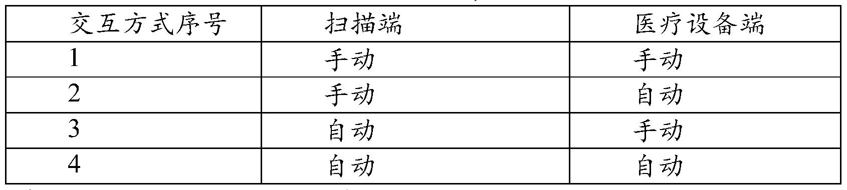
- the medical device end and the scanning end switch the next bar code it can be divided into four ways as shown in the following table.
- the scanning mode of the scanning end is as follows:
- FIG. 6 is a schematic diagram of a plurality of barcode scanning processes according to an embodiment of the present invention. As shown in FIG. 6, the method includes the following steps:
- Step 600 Open the scanning end and operate the medical device to display the first barcode for scanning.
- Step 605 Determine whether the scanning is successful; if the scanning is successful, perform step 610; otherwise, the step ends.
- Step 610 The scan end manually confirms that the scan is successful; and manually operates the medical device to display the next barcode;
- step 610 can be as follows according to different manners of interaction between the scanning end and the medical device end:
- the scanning end manually confirms that the scanning is successful; the medical device automatically detects the signal that the scanning end scans successfully, and automatically displays the next barcode;
- the scanning end does not need to confirm that the scanning is successful, and automatically switches to the scanning page; the medical device side manually operates the device to display the next barcode;
- the scanning end does not need to confirm that the scanning is successful, and automatically switches to the scanning page; the medical device automatically detects the signal that the scanning end scans successfully, and automatically displays the next barcode.
- Step 615 Determine whether the scan is successful; if successful, perform step 620; otherwise, the step ends.
- Step 620 Determine whether it is the last barcode; if yes, go to step 625; otherwise, go back to step 610.
- Step 625 The treatment information is displayed on the scanning end, and the user selects to submit to the server, and the step ends.
- FIG. 7 is a schematic flowchart diagram of a data transmission method of a medical device according to an embodiment of the present invention. This method is mainly applied to the data processing device side. As shown in Figure 7, the method includes:
- Step 700 Read the barcode output by the medical device.
- the barcode can be read by a barcode scanning device such as a scanner.
- the output barcode can also be read by means of photographing and reading.
- the device for taking a barcode can be a camera-capable terminal such as a mobile phone, a notebook computer, or a tablet computer, or other device having a shooting function.
- Step 705 Convert the read barcode to a transferable file.
- the transferable file is the original information or an advanced barcode.
- the original information is, for example, information having the same data format as the original use status information.
- the level of the advanced bar code is higher than the level of the multiple bar codes read, so that the advanced bar code has a larger information carrying capacity, so that all the information can be carried in an advanced bar code and delivered to the hospital or the hospital at one time. Three parties to provide ease of use.
- a plurality of serial codes can be converted into a two-dimensional barcode, a three-dimensional barcode or a composite code, a plurality of two-dimensional barcodes converted into a three-dimensional barcode or a composite code, and the like.
- Step 710 Transfer the transferable file. Since the transportable file is to be sent to a remote hospital or third party, the manner in which the file is transferred can be implemented over a communication network such as the Internet, a mobile communication network, or the like.
- the medical device data transmission method in the embodiment can be executed by using a computer, a mobile phone, or the like.
- the data interpretation and analysis functions are also required at the hospital or on the third party side.
- step 705 and step 710 may be used instead of step 705 and step 710. among them, Step 705: Parse the read barcode into treatment information and/or usage status information.
- Step 710 Generate a report based on the resolved treatment information and/or usage status.
- the method before or after parsing the read barcode as treatment information and/or usage status information, the method further comprises: verifying the barcode. If the barcode generation process is: forming the data frame according to certain rules according to the treatment information and/or the use condition information, and forming the barcode according to the data frame, verifying the barcode is: parsing the barcode, obtaining the data frame, and according to the obtained data frame The verification bit verifies the data segment in the data frame.
- FIG. 8 is a schematic flowchart diagram of a data transmission method of a medical device according to an embodiment of the present invention. This method is mainly applied to the data reading device side for reading the barcode outputted in the above embodiment.
- a character string is taken as an example of a barcode
- the user's treatment information for example, a ventilator can be a treatment time, AHI, SNI, air leakage, compliance, P95, etc.
- Practical status information still taking the ventilator as an example, it can be a parameter setting during operation pressure such as treatment pressure.
- a set of character strings is generated by a predetermined encoding rule, and the generated character string is a barcode.
- the method includes:
- Step 800 Obtain the serial number of the medical device.
- the camera function may be taken to capture the serial number of the medical device, and the picture may be submitted; or the picture of the existing serial number may also be used.
- OCR image recognition technology needs to be supported to extract the device serial number from the picture. This eliminates the complexity of manual operations and makes the user's operation easier.
- a manual input interface can also be provided for the user to manually input the serial number. If the device serial number fails to be extracted, an error message is displayed, and the user is required to repeat the step. If the extraction is successful, the process continues.
- Step 805 Verify the serial number of the medical device.
- verifying the serial number of the medical device includes verifying that the serial number of the medical device is correct, whether the included character is legal, or even comparing the serial number of the medical device pre-stored in the system. If the serial number of the medical device is unsuccessful, return to step 800; if the serial number of the medical device is verified to be successful, continue with the following steps.
- Step 810 Obtain iCode information of the medical device.
- a picture may be submitted in the form of a picture, or a picture of an already existing serial number may be used, or a manual input interface may be provided.
- Step 815 Verify the iCode information.
- Verify that iCode includes verifying that the length of the iCode is correct, whether the included characters are legal, and whether it matches the device serial number. If the verification is incorrect, go back to step 805; if successful, continue to the next step.
- step 805 the complete treatment information is composed of n groups of iCode
- Step 820 Generate a report according to the obtained serial number of the medical device and the iCode information.
- the user may choose to generate a web version report or a software version report. If the web version report is selected, the obtained serial number of the medical device and the iCode information are sent to the server, and the server verifies the legality of the received data, and generates a report if the user data is legal. Subsequently, the user (patient or medical institution's doctor) can get a report on the web page.
- the data information is encrypted, and a symmetric key or a public-private key may be used for encryption.
- the server first decrypts the received data first, and then verifies the validity of the data.
- the report after the report is generated, the report may be directly provided to the user for viewing, or the report may be sent to the specified mail, which is beneficial for saving the data in the future.
- steps 800 and 805 and steps 810 and 815 can be interchanged without affecting the implementation of the present invention.
- the benefits of verifying iCode are:
- the serial number of the medical device matches the iCode, that is, whether iCode is generated by the input machine; the serial number of the medical device has a corresponding relationship with iCode. If the serial number entered by the user is incorrect, all iCodes are wrong. If the serial number is correct, but iCode is wrong even if one character is wrong, iCode is considered to be wrong; only through this verification, the correct report can be generated. If the verification is not performed, directly parsing the data will generate an erroneous report; In an embodiment, at some point, the medical device may only generate the correct iCode of the group;
- iCode may contain certain information related to user medical reimbursement.
- the serial number information of the medical device and the iCode information form a two-dimensional code on the medical device side
- the serial number information and the iCode information of the medical device can be obtained by scanning the two-dimensional code. Once the serial number of the medical device and the iCode are obtained through the QR code scan, the serial number and iCode of the medical device can also be verified by the steps 805 and 810.
- the process of generating iCode information according to the treatment data and/or the use condition information, and generating the two-dimensional code according to the iCode information is as follows: encoding the medical treatment data and/or the use condition information according to the specified rule to generate the iCode code
- the generated iCode code is parsed according to the anti-rule; the data generated by the parsing is judged to be the same as the initial data; if the same, the iCode code is converted into a two-dimensional code display, and the two-dimensional code is generated successfully; if different, The QR code failed to generate, and the device can notify the user by error.
- the medical treatment data and/or the use condition information may be encoded according to a specified rule to generate an iCode code, and the iCode code is directly converted into a two-dimensional code display.
- the plurality of iCode code information may be generated into a two-dimensional code. It is also possible to generate a QR code directly from an original medical treatment data and/or usage status information.
- the specific iCode information and machine serial number are as follows; meanwhile, it is assumed that the multiple iCode information and the machine serial number have been verified:
- iCode 182 VLCG7UGHB0F01F2F
- the above iCode information records the treatment data and/or usage status information of the medical device for 1 day, 7 days, 30 days, 90 days, 182 days, and 365 days, respectively.
- the following ASCII code indicates the specific usage information of these days. .
- a two-dimensional code (not shown) may be generated after the plurality of iCode information is combined into one data frame; when the two-dimensional code is scanned, the obtained frame information is as follows. Note here that in addition to the iCode code information, the following table also adds the frame header " ⁇ ", the end of the frame "U”, and the check digit " ⁇ ". Of course, in actual applications, the data frame rules corresponding to the two-dimensional code can be customized, and are not limited to the following table.
- the user and the doctor can obtain the corresponding treatment data according to the iCode code by using the iCode decoding software installed on the mobile terminal or the webpage.
- the table below shows the corresponding treatment data above.
- the data frame may be directly generated by the treatment data and/or the use condition information, and then a two-dimensional code is generated according to the data frame (not shown in the text); when the two-dimensional code is scanned, the obtained information is as follows
- the table shows the 90-day usage information for medical devices:
- FIG. 9 is a schematic structural diagram of a medical device according to an embodiment of the present invention. As shown in Fig. 9, the medical device includes a detecting unit, a code converting unit, and an output unit.
- the detecting unit is configured to collect and use the medical condition information of the medical device.
- the code conversion unit is configured to convert usage status information detected by the detection unit into a barcode.
- the output unit is used to output a barcode converted by the transcoding unit.
- the output unit can be a display or a printer or other output component.
- FIG. 10 is a schematic structural diagram of a medical device according to another embodiment of the present invention. As shown in FIG. 10, the medical device further includes a control unit, a storage unit, a timer unit, and a statistical analysis unit based on the medical device shown in FIG.
- the control unit is operative to receive usage status information from the detection unit and to transmit usage status information to the transcoding unit and/or the storage unit.
- the storage unit is configured to store usage status information detected by the detecting unit; and/or barcode data obtained by the transcoding unit; and/or additional information such as user status information, device status information, measurement item name, management information, and the like.
- the timing unit is controlled by the control unit to record the time of use of the ventilation therapy device.
- the time output by the timing unit can be output to the control unit and provided by the control unit to the transcoding unit for conversion to a bar code in conjunction with other usage status information detected at that time/time period.
- the statistical analysis unit is controlled by the control unit and receives usage status information from the control unit to perform statistics and analysis on the usage status information.
- the various usage status information processed by the statistical analysis unit may be provided to the transcoding unit, and converted by the transcoding unit into a barcode to be sent to a hospital or a medical institution.
- various usage status information processed by the statistical analysis unit can also be directly provided to the control unit, Output directly from the output unit for the user to view.
- control unit is described as a necessary technical feature, in actual implementation, the medical device may not include the control unit, and at this time, the functions of the control unit are respectively in other Among the functional units.
- FIG. 11 is a schematic structural diagram of a medical device according to another embodiment of the present invention.
- the medical device unit further includes: an information dividing unit that divides the use state information of the medical device into a plurality of information units; wherein, the code conversion unit is configured to: Convert multiple information units into barcodes.
- FIG. 12 is a schematic structural diagram of a medical device according to another embodiment of the present invention.
- the medical device unit further includes: a signal receiving unit, configured to receive trigger information, where the currently displayed bar code group has been read, based on the medical device described in FIG. 9 or FIG. ; triggers the display of the next set of barcodes based on the trigger information.
- the signal receiving unit may be a light sensor or a sound sensor.
- the signal receiving unit may also be a device that transmits an electrical signal or the like.
- any two or more of the above-mentioned modular units may be integrated into one body to form a composite functional unit; the composite functional unit may be considered as a combination of a plurality of functional units.
- the free combination between all the above modular units and the combination with the prior art, as long as the formation of an implementable technical solution, is within the scope of the present disclosure.
- FIG. 13 is a schematic structural diagram of a ventilator according to an embodiment of the present invention.
- the ventilator is composed of a power supply system, a motor system, a flow sensor 3, a humidity collecting unit 4, a display unit 5, an SD card 6, a UART 7, a trigger information receiving unit 8, a button 9, a processor 10, and a pressure
- the ventilator is composed of a power supply system, a motor system, a flow sensor 3, a humidity collecting unit 4, a display unit 5, an SD card 6, a UART 7, a trigger information receiving unit 8, a button 9, a processor 10, and a pressure
- the click detection system is composed of a power supply system, a motor system, a flow sensor 3, a humidity collecting unit 4, a display unit 5, an SD card 6, a UART 7, a trigger information receiving unit 8, a button 9, a processor 10, and a pressure
- a pressure The structure of the click detection system.
- the power supply system further includes a voltage converter 11 for converting an external voltage into a 24V DC voltage; a current filter 12; a voltage converter 13 that converts the output of the current filter 12 to 15V to supply power to the drive circuit of the motor system; 14.
- the output of the voltage converter 11 is converted to a 5V DC voltage, which supplies power to the buzzer and pressure acquisition, and serves as an input to the voltage converters 15, 16, 17.
- the voltage converters 15, 16, and 17 respectively convert the 5V DC voltage to 3.3V, and supply power to the motor control circuit, the flow sensor, and the processor and peripheral circuits, respectively.
- the motor system is composed of a motor control circuit 24, a drive circuit 21, a current and back electromotive force drive unit 23, and a motor 22.
- the pressure and click detection system includes a pressure and click detection unit 31, an amplification 32, and a buzzer alarm 33.
- the motor output flow rate and pressure are respectively detected using the pressure and click detecting unit 31 and the flow sensor 3 to control the pressure and flow rate of the air supplied to the patient, and the click signal is measured by the pressure and click detecting unit 31.
- UART7 is a signal input/output interface for communication with a PC. This signal input/output interface enables software upgrade and data transmission to the PC for playback.
- the data is stored by the SD card 6, and the SD card 6 is read and written by the processor 10.
- the communication mode can use the SPI bus.
- the data stored in the SD card 6 can be output by the processor 10 to the PC through the UART 7, or The SD card 6 is taken out, and the data is output to the PC through the card reader.
- the trigger information receiving unit 8 is a light/sound sensor to check a signal that the data reading device successfully reads the barcode displayed by the display unit 5.
- the remote data transmission method described above is implemented by software, and the software is installed on the processor 10 through the UART 7.
- the processor 10 passes the pressure and click detection unit 31, the flow sensor 3, and the humidity described above.
- the sensor 4 collects the medical data of the patient in the ventilator state, and displays the barcode corresponding to the medical data in the display unit 5, and automatically performs the barcode in the form of the display unit 5 according to the signal received by the light/sound sensor 8.
- the display is updated; the user can also select to control the display of the barcode on the display unit 5 by means of the button 9; of course, the generated barcode can also be stored in the SD card 6 at the same time.
- the SD card 6 is not a necessary technical feature; at the same time, the specific selection of the power system will vary depending on the selection of the motor system, the flow sensor 3, the processor 10, and the buzzer alarm 33.
- FIG. 14 is a schematic structural diagram of a ventilator according to an embodiment of the present invention.
- the ventilator shown in FIG. 13 further includes a barcode generating unit 18, which is connected to the processor 10 and the display unit 5, which is one input according to The specific format of the information generates a hardware chip/module of the barcode that communicates with the processor 10 through a particular interface.
- the main function of the processor 10 is to collect the medical data of the patient in the state of the ventilator by the pressure and click detecting unit 31, the flow sensor 3, and the humidity sensor 4 described above, and The medical data is output to the barcode generating unit 18 in a specific data format, and the barcode generating unit 18 outputs the barcode according to the input data format; and under the control of the processor 10 (either automatic update control by the light/sound sensor 8) It is also possible to realize manual control by means of the button 9, and output the barcode in the display unit 5.
- a certain ventilator may also include only the barcode generating unit 18, and does not include the trigger information receiving unit 8.
- a ventilator can further delete one or more components shown in FIG. 13 and FIG. 14 according to changes in the function of the ventilator, or further include one or more components, both of which are Within the scope of protection of the present invention.
- FIG. 15 is a schematic structural diagram of a data reading apparatus according to an embodiment of the present invention.
- the data reading device and the scanning terminal mentioned in the above embodiment may be the same device.
- the data reading device includes:
- the reading unit may include a scanner or a hardware device with barcode scanning software. Since the step of reading the outputted plurality of barcodes is performed at the use end of the medical device, the reading unit may be a camera device, such as a mobile phone, a notebook computer, a tablet computer, or the like, for the convenience of the user. It can be other devices with shooting functions.
- the reading unit upon successful completion of reading a certain or a set of barcodes, generates a trigger signal for detection by the medical device signal receiving unit. Once the medical device signal receiving unit receives the trigger signal, an automatic page turning/update display of the bar code can be triggered.
- the reading unit can be divided into a receiving subunit and a parsing subunit.
- the receiving subunit is configured to receive a barcode output by the medical device; and the parsing subunit is configured to interpret (parse) the barcode into data that can be analyzed by the medical staff and/or the medical device.
- the data reading device further includes a report generating unit configured to generate a report based on the data interpreted by the interpretation subunit.
- the method further includes: a confirmation unit, configured to include a device body in the barcode When the information and the user identity information are confirmed, it is confirmed whether the device identity information and the user identity information match; if the content is met, the interpretation unit further analyzes, if not, the analysis is rejected, and the rejection information is sent.
- the rejection information can be an alarm signal.
- the confirmation unit may further trigger the sending of the decision information back to the patient's and/or medical staff's mobile phone, computer or other terminal; this can avoid analyzing the usage status information of multiple users in the hospital or medical institution. An error occurred.
- the reading unit further converts the barcode into a transferable file.
- the data reading apparatus of the embodiment of the present invention further includes a transmission unit for transmitting the transferable file.
- the transmission unit may be a communication device supporting a communication network (Internet, 3G network, etc.) or the like, such as a mobile phone, or a computer capable of connecting to a communication network.
- the reading unit and the transmission unit may be an integrated device, and the integrated device may be a mobile phone having a photographing function or a computer having a photographing function and being connectable to a communication network.
- the integrated device may be a mobile phone having a photographing function or a computer having a photographing function and being connectable to a communication network.
- the parsing unit can also be provided as a stand-alone system, which can be either a software running on the terminal device, and the patient or doctor can install the software on his own PC device or handheld device.
- the software to realize the parsing and plain text display of the barcode; or a service running on the web the patient or the doctor can input the obtained serial code information to the web website, and the web website provides the barcode analysis for the patient or the doctor. And plain text display.
- a storage medium storing a software program for implementing a remote data transmission method for a medical device described in the embodiment of the present invention is further provided, in an existing device having a processor function and capable of collecting information with the medical device
- the purpose of the embodiments of the present invention can be achieved by running the software stored on the storage medium on the system and the device on which the display unit communicates.
- An embodiment of the present invention further provides a storage medium storing a software program for implementing the data reading method described in the embodiment of the present invention, and the existing device having a barcode scanning function (or having a camera function and a barcode recognition function)
- the purpose of the embodiments of the present invention can be achieved by running software stored on the storage medium.
Abstract
提供了一种医疗设备远程信息传输方法。该方法包括:采集检测医疗设备中的治疗数据和/或使用状况信息(300);将采集检测到的医疗设备中的治疗数据和/或使用状况信息转换为条形码(305);根据所述医疗设备的输出装置类型,输出转换的条形码(310)。还提供了一种医疗设备、数据读取方法以及数据读取装置。所述医疗设备远程信息传输方法、医疗设备、数据读取方法以及数据读取装置能够在不对医疗设备进行改造的情况下,实现医疗数据的远程运输。
Description
医疗设备远程信息传输方法、 医疗设备
交叉引用信息 本申请请求申请号为 201210245802.x的中国申请的优先权, 该申请的申请 日为 2012年 7月 16 日; 本申请还请求申请号为 201210245837.3的中国申请的 优先权, 该申请的申请日为 2012年 7月 16 日。 技术领域 本发明涉及医疗设备领域, 尤其涉及一种医疗设备远程信息传输方法、一种 医疗设备, 一种数据读取方法以及装置。 发明背景 随着医疗保健走入家庭, 目前市场上出现各种家庭医疗设备。其中部分医疗 设备需要把医疗设备的使用状态信息随时或周期性的传送给医院或第三方进行 信息分析。 目前, 这种医疗设备的使用状态信息的传输方法大体包括以下几种 方式: 利用互联网通信设备和 /或协议进行信息传输; 利用移动存储设备, 即在 医疗设备上设置移动存储设备, 用于存放使用状态信息, 再将该移动存储设备 寄给医院或第三方, 待医院或第三方确认信息后再寄回患者; 患者电话或当面 口述等。
但是, 目前的这些医疗设备信息传输方法都存在问题。 家庭用医疗设备实现 联网或增加移动存储设备会提高设备成本, 同时这部分成本对该医疗设备的医 疗效果没有实质性改变, 因此降低了患者的接受度。 而通过患者电话口述或当 面口述往往存在漏报、 错报现象, 隐瞒信息等情况, 造成医院或第三方信息分 析错误, 甚至治疗方案误判, 降低医疗效果。
因此,需要提供一种医疗设备远程信息传输方法和医疗设备远程信息传输装 置, 以解决现有技术中存在的上述问题。 发明内容 有鉴于此, 本发明实施例提供一种医疗设备远程信息传输方法、一种医疗设 备、 一种信息读取方法以及一种信息读取装置, 在不对医疗设备进行改造的情 况下, 实现医疗数据的远程传输。
其中, 本发明实施例提供一种医疗设备远程信息传输方法, 包括: 采集检测医疗设备中的治疗数据和 /或使用状况信息;
将采集检测到的医疗设备中的治疗数据和 /或使用状况信息转换为条形码; 根据所述医疗设备的输出装置类型, 输出转换的条形码。
本发明实施例提供的一种医疗设备, 包括:
检测单元, 用于采集检测医疗设备的使用状况信息。
代码转换单元, 用于将检测单元检测的使用状态信息转换为条形码。
输出单元, 用于输出代码转换单元转换的条形码。
本发明实施例提供的一种信息读取方法, 包括:
读取医疗设备输出的条形码;
解析所述读取出的条形码为治疗信息和 /或使用状况信息;
根据解析的治疗信息和 /或使用状况, 生成报告。
本发明实施例提供的一种信息读取装置, 包括:
读取单元, 用于读取医疗设备输出的条形码;
解析单元, 用于解析所述读取出的条形码为治疗信息和 /或使用状况信息; 报告生成单元, 用于根据解读子单元解读出来的数据生成报告。
综上所述, 利用本发明实施例提供的医疗设备远程信息传输方法、 医疗设备 以及信息读取装置, 将医疗设备监控到的数据转换为条形码, 并将条形码显示 在医疗设备原有的显示屏中, 这一过程并不需要任何的通信设备的安装或改造。 当需要将治疗数据传输给医院或医生时, 通过简单的外设装置读取条形码就可 快速将治疗数据传输到医院或医生, 既可以保证数据的准确性, 又可以避免使 用者窜改数据题。 另外, 以条形码的形式而非明文的形式显示在医疗设备屏幕 端, 可以向病人屏蔽一些不必要的信息, 这也是一种人性化医疗的一种体现。 附图简要说明 图 1为本发明实施例一种医疗设备数据传输系统的结构示意图。
图 2为本发明另一实施例一种医疗设备数据传输系统的结构示意图。
图 3为本发明实施例一种医疗设备数据传输方法的流程示意图。
图 4为本发明实施例一种医疗设备数据传输方法的流程示意图。
图 5为本发明实施例一种医疗设备数据传输方法的流程示意图。
图 6为本发明一实施例提供的多幅条形码扫描流程示意图。
图 7为本发明实施例一种医疗设备数据传输方法的流程示意图。
图 8为本发明实施例一种医疗设备数据传输方法的流程示意图。
图 9为本发明实施例一种医疗设备的结构示意图。
图 10为本发明另一实施例中一种医疗设备的结构示意图。
图 11为本发明另一实施例中一种医疗设备的结构示意图。
图 12为本发明另一实施例中一种医疗设备的结构示意图。
图 13为本发明实施例所述的一种呼吸机的结构示意图。
图 14为本发明另一实施例所述的一种呼吸机的结构示意图。
图 15为本发明实施例所示的一种数据读取装置的结构示意图。 实施本发明的方式 为使本发明的目的、技术手段和优点更加清楚明白, 以下结合附图对本发明 作进一步详细说明。
图 1为本发明实施例一种医疗设备数据传输系统的结构示意图。如图 1所示, 该系统包括:
医疗设备 100是具备一种功效的设备,该设备可以采集病人利用当前医疗设 备进行治疗时产生的各种治疗数据和 /或使用状况信息; 并将这些治疗数据和 /或 使用状态信息转换为条形码, 并将该条形码输出。 数据读取设备 105 可以扫描 读取医疗设备 100 输出的条形码, 并根据读取出的条形码信息生成医疗信息报 告, 发送到医疗机构或第三方。
在图 1示出的条形码为简单的一維码, 本领域技术人员可以理解,这仅仅是 为了简便起见。 实际上, 条形码的形式可以是多种多样, 在本发明一实施例中, 条形码优选地为国际标准化码, 例如串码 (例如 ASCII码,或其他编码方式的串 码)、一維码、 二維码、 三維码或复合码。 作为示例, 一維码可以为 JAN码、 ITF 码或 NW-7码等。 二維码可以为 QR (Quick Response) 码或 PDF417码等。 三 維码可以为日本公司 "Content Idea of Asia"研制的条形码。 复合码是上述码的 组合码。
在本发明一实施例中,数据读取设备可以是具备条形码扫描功能的现有的移 动终端或电子设备, 在这种情况下, 数据读取设备可以共用现有设备的其他功 能, 如摄像头、 蓝牙、 wifi等, 从而支持将生成的医疗信息报告以多种方式提供 给医疗机构或第三方。
在本发明一实施例中,数据读取设备 105读取出的医疗信息也可以是串码的 形式 (见后续实施例的描述), 在这种情况下, 还可以进一步提供一个串码解析 系统, 该串码解析系统可以安装在用户终端侧, 也可以是以 web服务的方式在 服务器端出现。 即, 用户既可以将获取的串码输入或发送到安装在用户终端侧 的本地软件 /本地系统, 通过输入的串码获取到对串码解码后的明文的治疗数据 和 /或使用状况信息,也可以将获取的串码输入或发送到安装在一个 web网站上, 以获取对串码解码后的明文的治疗数据和 /或使用状况信息。 在这种情况下, 直 接通过串码解析系统即可生成医疗信息报告。
利用本发明实施例提供的系统, 不需要对医疗设备本身做大的改造,如不需 要安装新的通信模块, 而是通过将各种治疗数据和 /或使用状况信息转换为条形 码的方式, 后续通过数据读取设备读取出来, 并传输到远端的医疗机构。 由于 数据读取设备可以与现有的移动终端或电子设备集成, 这样可以利用现有的移 动终端或电子设备的通信模块来延伸医疗设备的功能。 本发明实施例的这种方 式, 非常巧妙的利用条形码将没有远程通信模块的医疗设备与外部设备的远程 通信模块集合在一起。 同时, 利用条形码的方式, 既可以将治疗数据和 /或使用 状况信息的交互过程向病人或用户屏蔽, 又可以让用户选择指定传输到医疗机 构或第三方的数据范围 (通过指定扫描特定条形码的方式), 非常灵活。
图 2为本发明另一实施例一种医疗设备数据传输系统的结构示意图。如图 2 所示, 该系统与图 1 所示的系统差別在于, 该系统进一步在医疗设备或第三方 侧包含一个数据解析显示设备 200。此时,数据读取设备 105并不直接生成报告, 而是将条形码信息转换为可传输信息, 并将该可传输信息通过数据读取设备的 传输功能传输到数据解析显示设备 200 中。 数据解析显示设备 200接收到可传
输信息时, 解析该可传输信息, 获取条形码, 并进一步解析条形码获得医疗设 备和 /或使用状态信息, 并将该信息显示出来, 供医生参考。 在本发明一实施例 中, 当获取的条形码为串码形式时, 数据解析显示设备 200可以与图 1 所示的 串码解析系统为同一设备, 具有相同的功能。
同样, 本领域技术人员可以理解, 虽然图中仅示出一維码, 但实际上, 条形 码的形式可以是多种多样。
在本发明一实施例中, 该数据解析显示设备即可以是 PC终端, 也可以是手 机、 平板等手持终端; 只要该硬件设备具有数据接收和显示功能, 同时其具备 数据处理功能。
图 3为本发明实施例一种医疗设备数据传输方法的流程示意图。如图 3所示, 该医疗设备数据传输方法包括:
步骤 300 : 采集检测医疗设备中的各种治疗数据和 /或使用状况信息。
不同的医疗设备或者患者的病情不同 (医生的要求不同), 所需要采集的治 疗数据或使用状态信息会略有不同。 在本发明一实施例中, 可以提供用户接口, 将当前医疗设备所有可获取的治疗数据或使用状态信息供用户进行删选。 默认 状态下, 为全选模式。
比如, 当医疗设备为通气治疗设备时, 所述使用状况信息包括治疗天数、 平 均每天治疗时间和 /或治疗压力 (平均 P95压力或者平均 P90压力)。 当然, 还可 以包括呼吸紊乱指数(AHI: Apnea Hypopneas Index) ,鼾声指数和 /或漏气量等。
在本发明一实施例中,可以利用原有医疗设备的传感器采集检测医疗设备中 的各种治疗数据和 /或使用状况信息。 如通过设置在通气治疗设备内的压力传感 器、 流量传感器等对通气治疗设备提供的气体的压力和流量进行检测, 或通过 声音传感器对使用者的鼾声等声音信息进行检测。
在本发明一实施例中,可以通过设备额外的传感器来采集检测医疗设备中的 各种治疗数据和 /或使用状况信息。
所述使用状态信息包括治疗天数、 平均每天治疗时间、 治疗压力、 呼吸紊乱 指数、 鼾声指数和漏气量中的至少一种。
由于医院或医疗机构经常会同时会接收多名使用者的数据,在本发明一实施 例中, 为了能保证医院接收的信息的准确性, 所采集的使用状态信息还可以进 一步包括医疗设备的设备身份信息和 /或患者的身份信息。
其中, 设备身份信息可以是型号信息, 即只需要了解医疗设备类型, 无需设 备的唯一标示信息。 患者的身份信息可以是用户手动输入的信息, 该身份信息 可以是唯一标示的, 也可以不唯一标示。 当然, 如果使用的设备身份信息为唯 一标示信息, 那么也可以无需患者的身份信息。
步骤 305: 将采集检测到的医疗设备中的各种治疗数据和 /或使用状况信息 转换为条形码 (barcode:)。
所述条形码优选地为国际标准化码, 例如串码 (例如 ASCII码)、一維码、 二 維码、 三維码或复合码。 作为示例, 一維码可以为 JAN码、 ITF码或 NW-7码 等。 二維码可以为 QR (Quick Response) 码或 PDF417码等。 三維码可以为日 本公司 "Content Idea of Asia"研制的条形码。 复合码是上述码的组合码。 在本
发明一时实施例中, 条形码还可以是字符串实现。
由于不同编码方式可携带的数据量不同,因此根据具体医疗设备的信息数据 量需求确定条形码的种类。 例如, 功能较少的医疗设备可以仅将使用状态信息 转换为一維码; 功能较多且检测数据较多的医疗设备可以将使用状态信息转换 为串码、 二維码、 三維码或复合码。 当然也可以根据所需要转换的数据量选择 性转换为不同的码。
在本发明一实施例中, 可以是将治疗数据和 /或使用状况信息按照一定的规 则组成一个数据帧, 再将所述数据帧转换为条形码。
下表为一个医疗数据和 /或使用状况信息组成的一个数据帧的一个示例, 如 下表所示, 该数据帧由帧头、 信息、 校验码以及帧尾构成。 其中, 帧头和帧尾 可以是特定的, 校验码可以采取累加和校验或 CRC校验来校验整批数据的完整 性。 本领域技术人员可以理解, 下表仅仅为示例而已。

步骤 310: 根据医疗设备的输出装置类型, 输出转换的条形码。
在本发明一实施例中,如果当前医疗设备的输出装置为小型打印口, 则可以 将转换的条形码以打印的方式, 纸件形式输出; 后续将记载有条形码信息的纸 件送至医院或医疗机构, 或可以利用后续记载的数据读取装置读取条形码后传 输至医院或医疗机构。 在本发明一实施例中, 如果当前医疗设备的输出装置为 显示屏, 则可以将转换的条形码显示在医疗设备的显示屏中; 后续可以利用后 续记载的数据读取装置读取条形码后传输至医院或医疗机构。
在本发明一实施例中, 如果当前医疗设备的输出装置为类似 U SB接口这样 的电子接口, 则可以将转换的条形码以电子的形式输出到外部存储器, 如 U盘; 后续可以将外部存储器的数据提供给至医院或医疗机构。
在本发明一实施例中, 还可以是先将采集和检测到的治疗数据和 /或使用状 态信息存储在医疗设备中, 再将一段时间的治疗数据和 /或使用状态信息转换为 条形码。 还可以将转换后的条形码存储在医疗设备中, 以供后续调用。 另外, 还可以在医疗设备中预先存储附加信息, 包括使用者状态信息、 设备状态信息、 测量项目名、 管理信息等, 以供转换条形码时调用。
在本发明另一实施例中, 当需要对医疗设备的总使用时间(患者第一次使用 该设备开始至医院接受数据时的总天数) 和平均每天使用的时间进行检测时, 还可以进一步记录医疗设备的使用时间, 以供转换条形码时调用, 与在该时刻 / 时间段检测的其它使用状态信息共同转换为条形码。
在本发明一实施例中,还可以对采集到的使用状态信息进行统计和分析,进
而用来评估用户的治疗效果, 以供医疗人员判断是否需要调整设备治疗参数。 统计分析后的结果可以进一步转换为条形码发送至医院或医疗机构。 当然, 统 计分析后的结果还可以直接提供给使用者查看。
图 4为本发明实施例一种医疗设备数据传输方法的流程示意图。如图 4所示, 该方法包括:
步骤 400: 将采集检测到的医疗设备中的各种治疗数据和 /或使用状况信息 转换为划分成多个信息单元。 这些信息单元将被转换为条形码, 以便由条形码 来承载信息单元所包含的信息。 其中本实施例所述条形码为上述实施例中条形 码形式的一种或几种,在此不再赘述。
该步骤可采取图 3所示实施例的步骤 305所记载的方法。
步骤 405: 将多个信息单元分別转换成多个条形码。
在这种情况下, 条形码中还进一步包括如数据标识、位置标识、 总数标识和 /或时间标识等控制数据。
其中, 数据标识用于标识当前条形码表示的信息单元所对应的 "文件", 以通 过数据标识判断每个条形码是否属于同一 "文件"; 这里所谓 "文件"指的是 "一 完整的治疗数据和 /或使用状况信息 "。
位置标识用于标识当前条形码表示的信息单元在整个 "文件 "中的位置或顺 序。
总数标识用于标识当前条形码所对应 "文件" 包含的信息单元的总数。 可以通过总数标识和已读取的条形码的数量来判断是否读取了同一 "文件" 的全部条形码。
时间标识用于标识每个条形码的输出时间以及输出剩余条形码所需要的剩 余输出时间, 以供使用者参考使用。
本领域技术人员可以理解, 条件码可以仅包含以上所述控制数据的部分。比 如在某些情况下, 可以无需包含总数标识; 在某些情况下, 可以不包含时间标 识; 或者两者均不包含也可以。
步骤 410:输出多个条形码。这里, 同样可以采取图 3所示实施例的步骤 310 所 i己载的方法。
在本发明一实施例中,如果采取显示屏的方式输出条形码, 可以设置一次性 地全部输出, 也可以依次且每次输出一个条形码。
本发明实施例提供的医疗设备数据传输方法和装置,将医疗信息分成多个条 形码进行传输、 可以满足大数据传输的需求。 另外, 在某些情况下, 受到二維 码生成模块和 /或数据扫描模块的性能影响, 将一个大数据划分成多个数据单元 进行二維码生成转化, 相比于将一个大数据直接转化生成为二維码, 效果更好, 速度更快, 这样可以解决一些处理能力不强的医疗设备的需求。
在本发明一实施例中, 也可以将多个信息单元转化为一个条形码。
图 5为本发明实施例一种医疗设备数据传输方法的流程示意图。如图 5所示, 该方法包括:
步骤 500: 采集检测到的医疗设备中的各种治疗数据和 /或使用状况信息转 换为条形码。
本领域技术人员可以理解,这里可以采取图 3所示步骤 305的方式进行转化, 也可以采取图 4所示步骤 400以及 405的方式进行转化。
步骤 505 : 将多个条形码进行分组, 后续显示时按组进行显示。
当信息量较大而显示装置的显示能力有限时, 可以将条形码分成多组, 以便 使多组条形码依次地显示在显示装置上。
在本发明一实施例中,可以将这些条形码均等地分组,也可以不均等地分组, 只要每组中包含至少一个条形码并能够由显示装置显示即可。 在极端情况下, 可以是一个条形码一组, 也可以是全部条形码一组。
步骤 510 : 当当前显示的条形码组被读取后, 接收触发信号, 其中, 所述触 发信号为当前显示的条形码被读取或读取完成时产生的信号; 根据该触发信息, 触发下一组条形码的显示; 直至显示完每一组条形码。
在本发明实施例中, 可以通过一个数据读取装置(本发明后续实施例会详细 讨论) 来读取显示的条形码, 以将该显示的条形码传给到医疗结构或第三方。 一旦捕捉到表示数据读取装置完成当前条形码的拍摄或扫描的触发信息, 即触 发显示下一组条形码; 然后再捕捉到表示数据读取装置完成该下一组条形码的 拍摄或扫描的触发信息, 继续显示下一组, 直到所有组的条形码都被拍摄或扫 描为止。 这也就是说, 拍摄或扫描的次数与条形码的组数相等。 一旦系统里没 有任何待显示的条形码组后, 则自动停止显示。
触发信号可以是由数据读取装置拍摄或扫描操作自动形成的, 如光信号和 / 或声音信号。 例如, 可以是数据读取装置的闪光灯产生的光信号和 /或扬声器产 生声音信息, 或扫描过程中产生的激光信号等等。
在本发明一实施例中,触发信号还可以为每组条形码被成功拍摄或扫描而产 生的信号, 例如, 数据读取装置成功读取显示的每组条形码时发出的信号, 以 确保在该组条形码被成功读取之后再显示下一组条形码。 当然, 触发信号也可 以是在条形码被读取前、 读取过程中, 或读取完成后发出的信号。 可以理解的 是, 该光信号和声音信号应当区分于环境中的光和声音。 可以通过控制信号的 强度、 信号的类型 (例如脉冲式光信号、 正弦波式光信号等) 以及信号的持续 时间等来与环境中的光和声音区分。
触发信号还可以是人为设定的任何信号,例如拍摄或扫描成功后人为设定而 自动产生的信号。 当然, 触发信号也可以是手动形成的, 例如通过患者手动按 键进行控制。
本发明实施例提供的方法能够根据拍摄或扫描每组条形码时或之后产生的 触发信号而自动或手动操作地显示下一组条形码, 因此可以提高工作效率, 避 免人为操作的失误。
本领域技术人员可以理解,上述多个实施例描述的医疗设备数据传输方法在 实际操作过程中可以任何组合。 只要这些组合的特征 (以及与任何现有技术的 任何组合) 是一个可实施的技术方案, 均在本发明的保护范围。
本发明实施例所述的医疗设备数据传输方法可以通过硬件或软件或软硬件 结合的方式实现。 如果通过软件来实现, 可以仅通过更新当前医疗设备控制中 心的软件来实现, 从而可以在几乎不对当前医疗设备中心做任何改动的方式下
(无需增加任何通信设备以及输出设备), 使得医疗机构可以远程获取医疗设备 采集和检测到的数据; 可以能够保证数据的准确性, 避免使用者窜改数据。 同 时, 条形码的输出方式, 保证了患者本人无法理解治疗数据的信息和内容, 非 常人性化。
在本发明以上实施例中,无论是步骤 405中将多个信息单元分別转换成多个 条形码, 还是步骤 505中将多个条形码进行分组, 都会涉及到多幅条形码的 交 互。 在本发明一实施例中, 可以在每幅条形码中加入校验信息。 在本发明另一 实施例中, 可以在每幅条形码中加入整组 /批码中条形码的总幅数和本幅条形码 的序号, 这样扫描端在扫描时, 将对多幅二維码的排序无任何要求, 可以是连 续的, 且起点可以从任何一幅开始, 甚至可以是离散的。 只要成功扫描到该组 的所有序号的二維码, 将会提示用户本组二維码扫描完成; 同时, 增加序号信 息可以避免读取出错后, 重新从第一幅图读取。 可以设置一个存储器, 将生成 的条形码暂存在存储器中, 如果出现条形码读取错误, 可以直接调阅相应的图 片序号进行数据读取, 保证了信息的准确性和连续性。 在本发明一实施例中, 还可以对已经扫描过或未扫描过的条形码进行标识, 防止漏扫或者重复扫描。
在本发明一实施例中,用户即可以在医疗设备端选择手动切换到下一幅条形 码的扫描, 也可以选择采取图 5 所示实施例自动切换到下一幅条形码的扫描; 还可以是扫描端选择通过按键或自动选择显示下一幅待扫描的条形码。 根据医 疗设备端和扫描端切换下一幅条形码的方式, 可以分为如下表的 4种方式。
其中, 扫描端切换方式如下表所示:

步骤 600 : 打开扫描端并操作医疗设备, 显示第一幅条形码, 以供扫描; 步骤 605 : 判断扫描是否成功; 如果扫描成功, 执行步骤 610; 否则, 步骤 结束。
步骤 610: 扫描端手动确认扫描成功; 并手动操作医疗设备显示下一幅条形 码;
本领域技术人员可以理解,根据扫描端和医疗设备端交互方式的不同, 步骤 610还可以是如下几种方式:
扫描端手动确认扫描成功; 医疗设备自动侦测扫描端扫描成功的信号,并自 动显示下一幅条形码;
扫描端无需确认扫描成功, 自动切换到扫描页面; 医疗设备端手动操作设备 显示下一幅条形码;
扫描端无需确认扫描成功, 自动切换到扫描页面; 医疗设备自动侦测扫描端 扫描成功的信号, 并自动显示下一幅条形码。
步骤 615 : 判断扫描是否成功; 如果成功, 则执行步骤 620; 否则, 步骤结 束。
步骤 620: 判断是否为最后一幅条形码; 如果是, 则执行步骤 625 ; 否则, 回到步骤 610。
步骤 625 : 治疗信息显示在扫描端, 并由用户选择递交到服务器, 此时步骤 结束。
图 7为本发明实施例一种医疗设备数据传输方法的流程示意图。该方法主要 应用于数据处理装置侧。 如图 7所示, 该方法包括:
步骤 700: 读取医疗设备输出的条形码。
作为示例,可以通过扫描器等条形码扫码装置来读取条形码。在本发明一实 施例中, 还可以通过拍摄读取的方式来读取输出的条形码。 拍摄条形码的装置 可以为手机、 笔记本电脑、 平板电脑等有摄像功能的终端, 也可以是其它具有 拍摄功能的装置。
本领域技术人员可以理解,在该步骤中也可以采取图 6所示实施例的数据验 证方式 (验证治疗数据和 /或设备工作状态与设备序列号之间的匹配度等)。
步骤 705 : 将读取的条形码转换为可传输文件。 可传输文件为原信息或高级 条形码。 原信息例如是与原使用状态信息具有相同数据格式的信息。 高级条形 码的等级高于读取的多个条形码的等级, 以使高级条形码具有较大的信息承载 量, 这样就可以将所有信息都承载在一个高级条形码中, 并一次性地输送至医 院或第三方, 以提供使用的便利性。 例如可以将多个串码 (即 ASCII码) 转换 为一个二維条形码、 一个三維条形码或一个复合码、 将多个二維条形码转换为 一个三維条形码或一个复合码等。
步骤 710: 传输可传输文件。 由于该可传输文件将要发送至远程的医院或第 三方, 因此传输该文件的方式可以通过互联网、 移动通信网络等的通讯网络实 现。
在本发明一实施例中,可以利用电脑、手机等来执行本实施例中的医疗设备 数据传输方法。
在这种情况下, 医院或第三方侧还需要具备数据解读以及分析功能。
在本发明一实施例中, 还可以是用步骤 705,和步骤 710,来替代步骤 705和 步骤 710。 其中,
步骤 705,: 将读取出的条形码解析为治疗信息和 /或使用状况信息。
步骤 710,: 根据解析的治疗信息和 /或使用状况, 生成报告。
在本发明一实施例中, 在解析所述读取出的条形码为治疗信息和 /或使用状 况信息之前或之后, 进一步包括: 验证所述条形码。 如果条形码的生成过程为: 将治疗信息和 /或使用状况信息按照一定的规则形成数据帧, 并根据数据帧形成 条形码, 则验证条形码为: 解析条形码, 获得数据帧, 并根据获得的数据帧中 的验证位验证数据帧中的数据段。
图 8为本发明实施例一种医疗设备数据传输方法的流程示意图。该方法主要 应用于数据读取装置侧, 用于读取以上实施例中输出的条形码。 在该实施例中, 以字符串作为条形码为例进行说明, 将用户的治疗信息 (如以呼吸机为例, 可 以是治疗时间, AHI、 SNI、 漏气量、 顺应性、 P95等) ,以及实用状况信息 (仍 以呼吸机为例, 可以是治疗压力等运行时的参数设置) 通过预定的编码规则生 成一组字符串, 该生成的字符串即为条形码。 为便于描述, 我们在以下实施例 中, 以 icode代表这种条形码。 如图 8所示, 该方法包括:
步骤 800: 获取医疗设备的序列号。
在本发明一实施例中,可以采取拍照功能拍摄医疗设备的序列号,提交图片; 也可以使用已经存在的序列号的图片。 这种情况, 需支持 OCR图像识別技术, 从图片中提取设备序列号。 这样可以免去手动操作的复杂性, 使用户操作更简 便。
在本发明一实施例中, 还可以提供手动输入界面, 供用户手动输入序列号。 若提取设备序列号失败, 则提示错误信息, 并要求用户重复该步骤, 若提取 成功, 则继续往下执行。
步骤 805: 验证医疗设备的序列号。
在本发明一实施例中,验证医疗设备的序列号包括验证医疗设备的序列号是 否正确、 包涵的字符是否合法, 甚至可以与系统里预存储的医疗设备序列号进 行对比。 如果验证医疗设备的序列号不成功, 则返回到步骤 800 ; 若验证医疗设 备的序列号成功, 则继续执行以下步骤。
步骤 810 : 获取医疗设备的 iCode信息。
在本发明一实施例中, 也可以如步骤 800所述, 采取拍照提交图片的形式, 或使用已经存在的序列号的图片, 或可以提供手动输入界面。
若提取 iCode失败,则提示错误信息,并要求用户重复该步骤,若提取成功, 则继续往下执行。
步骤 815: 验证 iCode信息。
验证 iCode包括验证 iCode的长度是否正确、 包涵的字符是否合法、 是否与 设备序列号匹配, 若验证有误, 则回到步骤 805 ; 若成功, 则继续下一步骤。
在这里,若完整的治疗信息由 n组 iCode组成,则在当前 iCode验证成功后, 可以继续回到步骤 805, 继续添加下一组与序列号匹配的 iCode信息, 直至所有 n组 iCode信息添加完毕, 则继续下一步骤。
步骤 820 : 根据获取的医疗设备的序列号以及 iCode信息, 生成报告。
在本发明一实施例中, 用户可以选择产生网页版报告或软件版报告。
如果选择网页版报告,则将获取的医疗设备的序列号以及 iCode信息发送到 服务器, 由服务器验证收到的数据的合法性, 并在用户数据合法的情况下, 生 成报告。 后续, 用户 (病人或医疗机构的医生) 可以在网页上获得报告。
在本发明一实施例中,在将获取的医疗设备的序列号以及 iCode信息发送到 服务器前, 对这些数据信息加密, 可以采取对称密钥或公私密钥加密的方式。 此时, 服务器端先首先解密收到的数据, 再验证数据的合法性。
如果选择软件版报告, 则可以直接根据获取的医疗设备的序列号以及 iCode 信息产生报告。
无论采取何种方式生成报告, 都可以利用采用 CRC校验解析数据。
在本发明一实施例中, 生成报告后, 可以选择直接将报告提供给用户查看, 也可以选择将报告发送到指定的邮件, 有利于以后数据的保存。
本领域技术人员可以理解, 在有些实施例下, 步骤 800和 805 与步骤 810 和 815的顺序可以交换, 并不影响本发明的实施。
这里, 以上实施例中, 对 iCode进行验证的好处有:
检测 iCode信息是否正确, 防止用户误操作或图像识別出错; 如果出错, 提 示用户重新提交信息;
检测医疗设备的序列号和 iCode是否匹配,即 iCode是否由输入的机器产生; 医疗设备的序列号和 iCode有对应的关系, 若用户输入的序列号有误, 则所有的 iCode都是错误的, 若序列号正确, 但 iCode哪怕一个字符有误, iCode被认为 是错误的; 只有通过这种验证, 才能产生正确的报告, 若不进行验证, 直接解 析数据会产生错误的报告; 在本发明一实施例中, 某一时刻, 医疗设备可能只 能产生唯——组正确的 iCode;
防止用户对 iCode的篡改, 以达到自己的某种目的; 原因在于, iCode可能 会包含某些涉及到用户医疗报销的信息。
当然,如果医疗设备的序列号信息以及 iCode信息在医疗设备端形成了二維 码, 则通过扫描二維码即可获取医疗设备的序列号信息以及 iCode信息。一旦通 过二維码扫描获取了医疗设备的序列号以及 iCode后,也可以采取步骤 805和步 骤 810的方式对医疗设备的序列号和 iCode进行验证。
在本发明一实施例中, 根据治疗数据和 /或使用状况信息生成 iCode信息, 并根据 iCode信息生成二維码的过程如下: 将医疗治疗数据和 /或使用状况信息 按照指定规则编码生成 iCode码; 将生成的 iCode码按反规则解析; 判断解析生 成的数据与初期的数据是否相同; 如果相同, 则将 iCode码转换为二維码显示, 此时生成二維码成功; 如果不同, 则表示生成二維码失败, 设备可通过报错通 知用户。 在本发明一实施例中, 也可以是将医疗治疗数据和 /或使用状况信息按 照指定规则编码生成 iCode码, 将 iCode码直接转换为二維码显示。
在本发明一实施例中, 可以是将多个 iCode码信息生成二維码。也可以根据 一个原始医疗治疗数据和 /或使用状况信息直接生成二維码。
下面以实际例子来说根据医疗治疗数据和 /或使用状况信息生成 iCode信息 以及二維码信息的过程。
假设医疗设备根据治疗数据和 /或使用状况信息已经生成了多个 iCode信息,
具体 iCode信息和机器序列号如下; 同时, 假设该多个 iCode信息和机器序列号 均已经通过验证:
机器序列号: 1208D589
iCode 1 : UM6R2KGHC0802K3Q
iCode 7: QX7088GHD0G01G2N
iCode 30: WN7Q7UGHB0F01F2F
iCode 90: P09L7UGHB6F01F2F
iCode 182: VLCG7UGHB0F01F2F
iCode 365: VCJ77UGHB0F01F2F
上述 iCode信息分別记录了医疗设备 1 天、 7天、 30天、 90天、 182天和 365天的治疗数据和 /或使用状况信息, 后面的 ASCII码, 分別表示了这些天中 具体的使用信息。
此时,可以根据该多个 iCode信息组合为一个数据帧后,生成一个二維码(未 在文中示出); 当扫描该二維码时, 得到的帧信息如下。 这里注意, 下表中除了 iCode码信息外, 还加入了帧头 " ¥", 帧尾 " U", 和校验位 "{ "。 当然实际应用 中, 可以自定义二維码对应的数据帧规则, 并不限于下表所示。

一旦获得上述 iCode信息后,用户和医生利用自身移动终端或网页端安装的 iCode解码软件, 根据 iCode码, 可以获取如对应的治疗数据。 比如, 下表为上 述对应的治疗数据。

在一个例子中, 也可以将治疗数据和 /或使用状况信息直接生成数据帧, 然 后根据该数据帧生成二維码 (未在文中示出); 当扫描该二維码时, 得到的信息 如下表所示为医疗设备 90天的使用信息:

图 9为本发明实施例一种医疗设备的结构示意图。如图 9所示, 该医疗设备 包括检测单元、 代码转换单元和输出单元。
检测单元用于采集检测医疗设备的使用状况信息。
代码转换单元用于将检测单元检测的使用状态信息转换为条形码。
输出单元用于输出代码转换单元转换的条形码。其中,输出单元可以是显示 器或打印机或其它输出部件。
图 10为本发明另一实施例中一种医疗设备的结构示意图。如图 10所示, 该 医疗设备在图 9 所示的医疗设备基础上, 进一步包括控制单元、 存储单元、 计 时单元、 统计分析单元。
控制单元用于从检测单元接收使用状态信息,并将使用状态信息发送给代码 转换单元和 /或存储单元。
存储单元用于存储检测单元检测出的使用状态信息; 和 /或代码转换单元转 化得到的条形码数据; 和 /或如使用者状态信息、 设备状态信息、 测量项目名、 管理信息等附加信息。
计时单元由控制单元控制以记录通气治疗设备的使用时间。可以将计时单元 输出的时间输出到控制单元中, 并由控制单元提供给代码转换单元与在该时刻 / 时间段检测的其它使用状态信息共同转换为条形码。
统计分析单元由控制单元控制, 并从控制单元接收使用状态信息, 以对使用 状态信息进行统计和分析。 统计分析单元处理后的各种使用状态信息, 可以提 供给代码转换单元, 由代码转换单元转换为条形码发送至医院或医疗机构。 当 然, 统计分析单元处理后的各种使用状态信息还可以直接提供给控制单元, 以
由输出单元直接输出后供使用者查看。
本领域技术人员可以理解, 虽然在图 10的描述中,控制单元作为必要技术 特征进行描述, 但在实际实现中, 医疗设备也可以不包含控制单元, 此时, 控 制单元的功能分別在其他各个功能单元之中。
图 11为本发明另一实施例中一种医疗设备的结构示意图。如图 11所示, 该 医疗设备单元在图 9 所述的医疗设备基础上, 进一步包括: 信息划分单元, 将 医疗设备的使用状态信息划分成多个信息单元; 这时, 代码转换单元用于将多 个信息单元分別转换成条形码。
图 12为本发明另一实施例中一种医疗设备的结构示意图。如图 12所示, 该 医疗设备单元在图 9或图 10所述的医疗设备基础上, 进一步包括: 信号接收单 元, 用于接收触发信息, 该触发信息表示当前显示的条形码组已被读取; 根据 该触发信息, 触发下一组条形码的显示。 在本发明一实施例中, 该信号接收单 元可以为光传感器或声音传感器。 当然, 信号接收单元还可以为传输电信号的 装置等。
需要说明的是, 上述提到的所有模块单元任意两者或更多者可以集成为一 体, 以形成为复合功能单元; 该复合功能单元可以认为是多个功能单元的组合。 同时, 以上所有模块单元之间的自由组合以及与现有技术的结合, 只要形成可 实施的技术方案, 均属于本发明公开的范围。
还需要说明的是, 上述提到的所有模块单元均可以由硬件、 软件、 固件或上 述的任意组合来实现。
图 13为本发明实施例所述的一种呼吸机的结构示意图。如图 13所示,该呼 吸机由电源系统、 电机系统、 流量传感器 3、 湿度采集单元 4、 显示单元 5、 SD 卡 6、 UART7、 触发信息接收单元 8、 按键 9、 处理器 10、 压力及鼾声检测系统 构成。
其中, 电源系统又包括电压转换器 11, 将外部电压转换为 24V直流电压; 电流滤波 12 ; 电压转换器 13, 将电流滤波 12的输出转换为 15V, 为电机系统 的驱动电路供电; 电压转换器 14,将电压转换器 11的输出转换为 5V直流电压, 为蜂鸣器及压力采集供电, 同时作为电压转换器 15、 16、 17的输入。 电压转换 器 15、 16、 17分別将 5V直流电压转换为 3.3V, 并分別为电机控制电路、 流量 传感器以及处理器及外围电路供电。电机系统由电机控制电路 24、驱动电路 21、 电流及反向电动势驱动单元 23 以及电机 22构成。 压力及鼾声检测系统包括压 力及鼾声检测单元 31、 放大 32以及蜂鸣器报警 33构成。 使用压力及鼾声检测 单元 31和流量传感器 3分別检测电机输出流速和压力, 以控制给患者提供的空 气的压力和流量, 并通过压力及鼾声检测单元 31 测量鼾声信号。 UART7 为与 PC 机进行通讯的信号输入 /输出接口, 可以通过该信号输入 /输出接口实现软件 升级和数据传输到 PC机进行回放的功能。 使用 SD卡 6对数据进行存储, 由处 理器 10对 SD卡 6进行读写, 通讯方式可以使用 SPI总线, 存储在 SD卡 6内 的数据可以是处理器 10通过 UART7输出到 PC机, 也可以将 SD卡 6取出, 通 过读卡器将数据输出到 PC机。 触发信息接收单元 8为光 /声感应器, 以检查数 据读取装置对显示单元 5 显示的条形码进行成功读取的信号。 在本发明一实施
例中,通过软件的方式实现以上描述的远程数据传输方法,将该软件通过 UART7 将该软件安装在处理器 10上, 处理器 10通过以上描述的压力及鼾声检测单元 31、 流量传感器 3、 湿度传感器 4采集病人在呼吸机状态下的医疗数据, 并将该 医疗数据对应的条形码显示在显示单元 5中, 同时根据光 /声感应器 8接收到的 信号, 对显示单元 5 形式的条形码进行自动地更新显示; 用户还可以选择通过 按键 9来控制条形码在显示单元 5 的显示; 当然, 也可以同时将生成的条形码 存储在 SD卡 6中。 本领域技术人员可以理解, SD卡 6并不是一个必要的技术 特征; 同时电源系统具体的选型会根据电机系统、 流量传感器 3、 处理器 10、 蜂鸣器报警 33的选型有所改变。
图 14为本发明实施例所述的一种呼吸机的结构示意图。如图 14所示,如图 14所示, 相比于图 13显示的呼吸机, 进一步包括条形码生成单元 18, 该条形 码生成单元 18与处理器 10和显示单元 5连接, 其为一个可以根据输入的特定 格式的信息生成条形码的硬件芯片 /模块, 与处理器 10 通过特定的接口进行通 信。 此时, 为了实现本发明实施例的目的, 处理器 10的主要功能为通过以上描 述的压力及鼾声检测单元 31、 流量传感器 3、 湿度传感器 4采集病人在呼吸机 状态下的医疗数据, 将该医疗数据按照特定的数据格式输出给条形码生成单元 18, 条形码生成单元 18根据输入的数据格式, 输出条形码; 并在处理器 10的 控制下 (既可以是通过光 /声感应器 8实现自动更新控制, 也可以通过按键 9实 现手动控制), 将条形码输出在显示单元 5中。
在本发明一实施例中, 某种呼吸机还可以只包含条形码生成单元 18, 而不 包含触发信息接收单元 8。 当然, 本领域技术人员还可以理解, 根据呼吸机的功 能变化, 某呼吸机还可以进一步删除图 13、 图 14中所示的一个或多个部件, 或 进一步包含一个或多个部件, 均在本发明的保护范围之内。
图 15为本发明实施例所示的一种数据读取装置的结构示意图。 在数据读取 装置与以上实施例中提到的扫描端可以是同一设备。 如图 15所示, 该数据读取 装置包括:
读取单元, 用于读取医疗设备输出的条形码。 在本发明一实施例中, 该读取 单元可以包括扫码器, 也可以是具备条形码扫描软件的硬件设备。 由于读取输 出的多个条形码的步骤是在医疗设备的使用端完成的, 为了方便使用者使用, 读取单元可以为拍摄装置, 例如手机、 笔记本电脑、 平板电脑等有摄像功能的 终端, 也可以是其它具有拍摄功能的装置。 在某一实施例中, 该读取单元一旦 成功完成对某一或一组条形码的读取后, 会产生触发信号, 可供医疗设备信号 接收单元检测。 一旦医疗设备信号接收单元接收到该触发信号后, 可以触发条 形码的自动翻页 /更新显示。
在某一些实施例中, 该读取单元可以分为接收子单元和解析子单元。 其中, 接收子单元用于接收医疗设备输出的条形码; 解析子单元, 用于将所述条形码 解读 (解析) 为可供医护人员和 /或医疗设备分析的数据。 在本发明一实施例中, 数据读取装置进一步包括报告生成单元, 用于根据解读子单元解读出来的数据 生成报告。 在本发明一实施例中, 可以有一个与读取单元独立的解析单元。
在本发明一实施例中, 进一步包括: 确认单元, 用于当条形码中包含设备身
份信息和使用者身份信息时, 确认设备身份信息和使用者身份信息是否相符; 如果符合则该解读单元进一步进行分析, 如果不符合则拒绝分析, 并发出拒绝 信息。 该拒绝信息可以是警报信号。 此外, 该确认单元还可以进一步触发将该 决绝信息发回至患者和 /或医护人员的手机、 电脑或其他终端; 这样可以避免在 医院或医疗机构内对多个使用者的使用状态信息进行分析时出现错误。
在本发明一实施例中, 读取单元进一步将条形码转换为可传输文件。
此时, 本发明实施例的数据读取装置进一步包括传输单元, 用于传输该可传 输文件。 由于该可传输信息将要发送至远程终端或服务器, 因此该传输单元可 以是支持通信网络 (互联网、 3G网络等) 等的通信设备, 如手机、 或者能够与 通信网络连接的电脑等。
在本发明一实施例中,读取单元和传输单元可以为一体装置,该一体装置可 以为具有拍摄功能的手机或具有拍摄功能且与能够与通信网络连接的电脑等。 这样可以实现读取步骤和处理步骤都无需增加额外的装置和费用, 只需要在手 机或电脑上安装具有相应处理功能的软件即可, 因此节省费用的同时还提高了 便利性。
如前实施例所述,该解析子单元还可以作为一个独立的系统提供,其既可以 是一个运行在终端设备的软件,病人或医生都可以将该软件安装在自己的 PC设 备或手持设备上, 通过该软件实现对条形码的解析和明文显示; 也可以是运行 在 web上的一个服务, 病人或医生可以将获取的串码信息输入到 web网站上, web网站为病人或医生提供条形码的解析和明文显示。
本领域技术人员可以理解, 以上实施例在技术描述时, 为了便于理解, 按照 系统、 方法、 装置的逻辑顺序进行了描述, 但所有在本申请中出现的实施例均 可以相互结合, 并不受描述的逻辑关系所限。
在本发明一实施例中,进一步提供存储有实现本发明实施例所描述的医疗设 备远程数据传输方法的软件程序的存储介质, 在一个具有处理器功能, 并能与 医疗设备的现有信息采集系统以及显示单元进行通信的设备上运行该存储介质 上存储的软件, 即可实现本发明实施例的目的。 本发明一实施例还进一步提供 存储有实现本发明实施例所描述的数据读取方法的的软件程序的存储介质, 在 现有具有条形码扫描功能 (或具有摄像功能以及条形码识別功能) 的设备上运 行该存储介质上存储的软件, 即可实现本发明实施例的目的。
本申请 PCT利用中文进行公开, 在后续进入国家阶段进行翻译时, 由于不 同语言对文字的处理方式不同, 会造成一些差异, 但这些差异不因成为影响本 发明范围的原因。 比如在进行中文翻译英文时, 一切因特指或不特指, 单数或 复数等照成的翻译差异, 都属于本发明的保护范围。
以上仅为本发明的较佳实施例而已, 并非用于限定本发明的保护范围。凡在 本发明的精神和原则之内, 所作的任何修改、 等同替换、 改进等, 均应包含在 本发明的保护范围之内。
Claims
1、 一种医疗设备远程信息传输方法, 包括:
采集检测医疗设备中的治疗数据和 /或使用状况信息;
将采集检测到的医疗设备中的治疗数据和 /或使用状况信息转换为条形码; 根据所述医疗设备的输出装置类型, 输出转换后的条形码。
2、 如权利要求 1所示的方法, 其特征在于, 进一步包括:
将采集检测到的医疗设备中的治疗数据和 /或使用状况信息划分成多个信息 单元;
则所述将采集检测到的医疗设备中的治疗数据和 /或使用状况信息转换为条 形码包括;
将多个信息单元分別转换成一个或多个条形码。
3、 如权利要求 2所述的方法, 其特征在于, 将多个信息单元分別转换成一 个或多个条形码时, 所述条形码中进一步包括以下一个或多个控制数据: 数据 标识、 位置标识、 总数标识和时间标识。
4、 如权利要求 1所述的方法, 其特征在于, 所述根据所述医疗设备的输出 装置类型, 输出转换的条形码包括:
将条形码进行分组显示;
所述方法进一步包括:
接收触发信号,其中, 所述触发信号为当前显示的条形码被读取或读取完成 时产生的信号; 根据所述触发信息, 触发下一组条形码的显示; 直至显示完每 一组条形码。
5、 如权利要求 4所述的方法, 其特征在于, 所述触发信号为拍摄或扫描操 作自动形成的光信号和 /或声音信号。
6、 如权利要求 1所述的方法, 其特征在于, 所述条形码为 ASCII码、 一維 码、 二維码、 三維码或复合码。
7、 如权利要求 1所述的方法, 其特征在于, 所所述将采集检测到的医疗设 备中的治疗数据和 /或使用状况信息转换为条形码包括:
将治疗信息和 /或使用状况信息按照一定的规则形成数据帧, 并根据所述数 据帧形成条形码。
8、 如权利要求 1所述的方法, 其特征在于, 所述将采集检测到的医疗设备 中的治疗数据和 /或使用状况信息转换为条形码包括:
将治疗信息和 /或使用状况信息通过预定编码规则生成一组字符串码, 将所 述字符串码作为条形码; 或
将治疗数据和 /或使用状况信息通过预定编码规则生成一组字符串码; 将所 述字符串码转换为二維码, 将所述二維码作为条形码。
9、 如权利要求 8所述的方法, 其特征在于, 在将所述字符串码转换为二維 码之前, 进一步包括: 将所述字符串码按反规则解析; 判断解析生成的数据与 起初的数据是否相同; 如果相同, 则将所述字符串码转换为二維码。
10、如权利要求 1所述的方法, 其特征在于, 所述使用状态信息包括以下信 息的一种或多种: 治疗天数、 平均每天治疗时间、 治疗压力、 呼吸紊乱指数、 鼾声指数和漏气量、 医疗设备的设备身份信息、 患者的身份信息。
11、 如权利要求 1所述的方法, 其特征在于, 进一步包括: 提供用户接口, 将所述医疗设备所有可获取的治疗数据或使用状态信息供用户进行选择; 采集 用户所选择的治疗数据或使用状态信息。
12、如权利要求 1所述的方法, 其特征在于, 所述根据医疗设备的输出装置 类型, 输出转换的条形码包括:
当所述医疗设备的输出装置为小型打印口,则利用纸件形式输出所述转换的 条形码, 以供后续数据读取装置读取并传输所述条形码; 或
当所述医疗设备的输出装置为显示屏,则将所述转换的条形码显示在所述显 示屏中, 以供后续数据读取装置读取并传输所述条形码; 或
当所述医疗设备的输出装置为电子接口,则将所述转换的条形码以电子的形 式输出到外部存储器。
13、 一种数据读取方法, 其特征在于, 包括:
读取医疗设备输出的条形码;
解析所述读取出的条形码为治疗信息和 /或使用状况信息;
根据解析的治疗信息和 /或使用状况, 生成报告。
14、 如权利要求 13所述的方法, 其特征在于,
在解析所述读取出的条形码为治疗信息和 /或使用状况信息之前或之后, 进 一步包括: 验证所述条形码。
15、 如权利要求 14所述的方法, 其特征在于, 所述条形码的生成过程为: 将治疗信息和 /或使用状况信息按照一定的规则形成数据帧, 并根据所述数据帧 形成条形码;
所述验证所述条形码为: 解析条形码, 获得数据帧, 并根据数据帧中的验证 位验证数据帧中的数据段。
16、 如权利要求 14所述的方法, 其特征在于, 所述条形码的生成过程为: 将治疗信息和 /或使用状况信息通过预定编码规则生成一组字符串码, 将所述字 符串码作为条形码; 或
将所述二維码作为条形码将治疗数据和 /或使用状况信息通过预定编码规则 生成一组字符串码; 将所述字符串码转换为二維码, 将所述二維码作为条形码; 所述验证条形码包括:验证所述字符串码的长度是否正确、包涵的字符是否 合法。
17、 如权利要求 16所述的方法, 其特征在于, 进一步包括:
获取医疗设备的序列号;
所述验证所述字符串码进一步包括:
验证所述字符串码是否与设备序列号匹配。
18、 如权利要求 13所述的方法, 其特征在于, 所述根据解析的治疗信息和 / 或使用状况, 生成报告包括:
将获取的条形码信息发送到服务器, 由服务器验证收到的数据的合法性, 并
在数据合法的情况下, 生成报告。
19、 一种医疗设备, 其特征在于, 包括:
检测单元, 用于采集检测医疗设备的治疗信息和 /或使用状况信息。
代码转换单元, 用于将检测单元检测的治疗信息和 /或使用状态信息转换为 条形码。
输出单元, 用于根据所述医疗设备的输出装置类型,输出代码转换单元转换 的条形码。
20、 如权利要求 19所述的医疗设备, 其特征在于, 包括:
信息划分单元, 将医疗设备的使用状态信息划分成多个信息单元; 则, 所述代码转换单元用于将多个信息单元分別转换成一个或多个条形码。
21、 如权利要求 19或 20所述的医疗设备, 其特征在于, 包括:
信号接收单元, 用于接受触发信息, 所述触发信息表示当前显示的条形码组 已被读取; 根据所述触发信息, 触发下一组条形码的显示。
22、 如权利要求 21所述的医疗设备, 其特征在于, 所述信号接收单元为光 传感器或声音传感器。
23、 一种数据读取装置, 其特征在于, 包括:
读取单元, 用于读取医疗设备输出的条形码;
解析单元, 用于解析所述读取出的条形码为治疗信息和 /或使用状况信息; 报告生成单元, 用于根据解析单元解读出来的数据生成报告。
24、 如权利要求 23所述的装置, 其特征在于, 所述解析单元和 /或报告生成 单元安装在用户终端侧, 或以 web服务的方式安装在服务器端。
Priority Applications (3)
| Application Number | Priority Date | Filing Date | Title |
|---|---|---|---|
| CN201380002105.4A CN104520855B (zh) | 2012-07-16 | 2013-07-15 | 医疗设备远程信息传输方法、医疗设备 |
| EP13820534.9A EP2874082B1 (en) | 2012-07-16 | 2013-07-15 | Information transmission method for medical equipment |
| US14/298,885 US9092705B2 (en) | 2012-07-16 | 2014-06-07 | Method of tele-transmitting information of a medical device and a medical device thereof |
Applications Claiming Priority (4)
| Application Number | Priority Date | Filing Date | Title |
|---|---|---|---|
| CN201210245837.3A CN102799915B (zh) | 2012-07-16 | 2012-07-16 | 信息传输方法和信息传输装置 |
| CN201210245802XA CN102880782A (zh) | 2012-07-16 | 2012-07-16 | 医疗设备远程信息传输方法和医疗设备远程信息传输装置 |
| CN201210245837.3 | 2012-07-16 | ||
| CN201210245802.X | 2012-07-16 |
Related Child Applications (1)
| Application Number | Title | Priority Date | Filing Date |
|---|---|---|---|
| US14/298,885 Continuation US9092705B2 (en) | 2012-07-16 | 2014-06-07 | Method of tele-transmitting information of a medical device and a medical device thereof |
Publications (1)
| Publication Number | Publication Date |
|---|---|
| WO2014012475A1 true WO2014012475A1 (zh) | 2014-01-23 |
Family
ID=49948281
Family Applications (1)
| Application Number | Title | Priority Date | Filing Date |
|---|---|---|---|
| PCT/CN2013/079412 WO2014012475A1 (zh) | 2012-07-16 | 2013-07-15 | 医疗设备远程信息传输方法、医疗设备 |
Country Status (4)
| Country | Link |
|---|---|
| US (1) | US9092705B2 (zh) |
| EP (1) | EP2874082B1 (zh) |
| CN (1) | CN104520855B (zh) |
| WO (1) | WO2014012475A1 (zh) |
Cited By (3)
| Publication number | Priority date | Publication date | Assignee | Title |
|---|---|---|---|---|
| CN107004237A (zh) * | 2014-09-05 | 2017-08-01 | 斯塔根有限公司 | 对就诊者的临床检查数据进行输出以及输入的方法 |
| CN107330485A (zh) * | 2017-06-21 | 2017-11-07 | 广州视源电子科技股份有限公司 | 一种医疗设备使用管理方法、系统和手持式终端设备 |
| US10892893B2 (en) | 2015-12-17 | 2021-01-12 | Fresenius Vial Sas | Method and system for key distribution between a server and a medical device |
Families Citing this family (19)
| Publication number | Priority date | Publication date | Assignee | Title |
|---|---|---|---|---|
| US10971266B2 (en) | 2012-11-26 | 2021-04-06 | Fisher & Paykel Healthcare Limited | Transfer of breathing assistance apparatus data |
| US9737649B2 (en) | 2013-03-14 | 2017-08-22 | Smith & Nephew, Inc. | Systems and methods for applying reduced pressure therapy |
| US10026505B2 (en) * | 2013-03-26 | 2018-07-17 | Hill-Rom Services, Inc. | Patient support with dynamic bar code generator |
| AU2015411394B2 (en) | 2015-10-07 | 2021-07-08 | Smith & Nephew, Inc. | Systems and methods for applying reduced pressure therapy |
| CA3023932A1 (en) | 2016-05-13 | 2017-11-16 | Smith & Nephew, Inc. | Automatic wound coupling detection in negative pressure wound therapy systems |
| US11369730B2 (en) | 2016-09-29 | 2022-06-28 | Smith & Nephew, Inc. | Construction and protection of components in negative pressure wound therapy systems |
| WO2019014141A1 (en) | 2017-07-10 | 2019-01-17 | Smith & Nephew, Inc. | SYSTEMS AND METHODS FOR INTERACTING DIRECTLY WITH A COMMUNICATION MODULE OF A WOUND PROCESSING APPARATUS |
| EP3432309A1 (en) * | 2017-07-21 | 2019-01-23 | Siemens Healthcare GmbH | Providing a failure parameter in medical cloud infrastruc-tures |
| DE102018201242A1 (de) * | 2018-01-26 | 2019-08-01 | Geuder Ag | Verfahren zur Übertragung mindestens einer Information von einem medizinischen Gerät zu einer Empfangseinrichtung für die mindestens eine Information |
| CN110971437A (zh) * | 2018-09-30 | 2020-04-07 | 深圳迈瑞生物医疗电子股份有限公司 | 一种体外诊断设备、体外诊断设备信息传送系统及方法 |
| WO2020078954A1 (en) * | 2018-10-16 | 2020-04-23 | Koninklijke Philips N.V. | A system and method for medical visit documentation automation and billing code suggestion in controlled environments |
| GB201820668D0 (en) | 2018-12-19 | 2019-01-30 | Smith & Nephew Inc | Systems and methods for delivering prescribed wound therapy |
| CN109903826A (zh) * | 2019-01-17 | 2019-06-18 | 宁波鑫义信息科技有限公司 | 一种院外体检登记、管理和反馈的方法 |
| CN109935288A (zh) * | 2019-03-08 | 2019-06-25 | 厦门纳龙科技有限公司 | 一种poct设备数据管理方法、系统以及计算机装置 |
| TR201908788A2 (tr) * | 2019-06-13 | 2019-07-22 | Arge Tibbi Cihazlar Sanayi Ve Ticaret Anonim Sirketi | Kare kod okuyuculu elektroterapi̇ si̇stemi̇ ve yöntemi̇ |
| CN110459288A (zh) * | 2019-06-27 | 2019-11-15 | 浙江大学 | 一种筛查先天性心脏病的方法、装置、设备及存储介质 |
| CN111340164A (zh) * | 2020-04-15 | 2020-06-26 | 广东阿诺捷喷墨科技有限公司 | 一种纹路防护系统 |
| US20220223278A1 (en) * | 2021-01-14 | 2022-07-14 | Impact Ip, Llc | Processing generated sensor data associated with lymphedema device usage |
| WO2024074468A1 (en) * | 2022-10-03 | 2024-04-11 | Resmed Sensor Technologies Limited | Compression mechanism for therapy data |
Citations (4)
| Publication number | Priority date | Publication date | Assignee | Title |
|---|---|---|---|---|
| CN1666221A (zh) * | 2002-07-09 | 2005-09-07 | 里弗兰医疗集团公司 | 计算机辅助诊断(cad)系统的输入/输出接口 |
| CN101652781A (zh) * | 2007-04-12 | 2010-02-17 | 皇家飞利浦电子股份有限公司 | 使用条码菜单配置和设置生命体征监护仪 |
| CN101976329A (zh) * | 2010-11-16 | 2011-02-16 | 刘彤 | 一种基于二维码技术的病历信息管理方法 |
| CN102880782A (zh) * | 2012-07-16 | 2013-01-16 | 北京怡和嘉业医疗科技有限公司 | 医疗设备远程信息传输方法和医疗设备远程信息传输装置 |
Family Cites Families (12)
| Publication number | Priority date | Publication date | Assignee | Title |
|---|---|---|---|---|
| US6088695A (en) * | 1996-09-17 | 2000-07-11 | Kara; Salim G. | System and method for communicating medical records using bar coding |
| JP2001353124A (ja) * | 2000-04-10 | 2001-12-25 | Olympus Optical Co Ltd | 内視鏡装置 |
| US6568596B1 (en) * | 2000-10-02 | 2003-05-27 | Symbol Technologies, Inc. | XML-based barcode scanner |
| US20080121688A1 (en) * | 2006-08-30 | 2008-05-29 | Becton, Dickinson And Company | Multiple Barcode Format Labelling System and Method |
| US7434724B2 (en) * | 2006-12-22 | 2008-10-14 | Welch Allyn, Inc. | Dynamic barcode for displaying medical data |
| JP4484896B2 (ja) * | 2007-04-26 | 2010-06-16 | キヤノン株式会社 | 画像処理装置及びその制御方法ならびにそのプログラム及び記憶媒体 |
| CN101281607B (zh) * | 2008-05-20 | 2011-04-27 | 方正国际软件(北京)有限公司 | 一种大信息容量的二维条码系统 |
| WO2010131629A1 (ja) * | 2009-05-11 | 2010-11-18 | インターナショナル・ビジネス・マシーンズ・コーポレーション | 電子棚札(esl)からコンテンツを取得していくセルフ買物支援 |
| US8394053B2 (en) * | 2009-11-06 | 2013-03-12 | Crisi Medical Systems, Inc. | Medication injection site and data collection system |
| CN201556193U (zh) * | 2009-11-17 | 2010-08-18 | 上海飞来飞去多媒体创意有限公司 | 电子互动虚拟翻书系统、电子互动虚拟控制系统 |
| CN102129585B (zh) * | 2011-03-03 | 2013-03-27 | 天地融科技股份有限公司 | 一种信息传输方法及系统、条形码显示及读取装置 |
| CN202171812U (zh) * | 2011-07-05 | 2012-03-21 | 北京爱创科技股份有限公司 | 条形码识别装置 |
-
2013
- 2013-07-15 CN CN201380002105.4A patent/CN104520855B/zh active Active
- 2013-07-15 WO PCT/CN2013/079412 patent/WO2014012475A1/zh active Application Filing
- 2013-07-15 EP EP13820534.9A patent/EP2874082B1/en active Active
-
2014
- 2014-06-07 US US14/298,885 patent/US9092705B2/en active Active
Patent Citations (4)
| Publication number | Priority date | Publication date | Assignee | Title |
|---|---|---|---|---|
| CN1666221A (zh) * | 2002-07-09 | 2005-09-07 | 里弗兰医疗集团公司 | 计算机辅助诊断(cad)系统的输入/输出接口 |
| CN101652781A (zh) * | 2007-04-12 | 2010-02-17 | 皇家飞利浦电子股份有限公司 | 使用条码菜单配置和设置生命体征监护仪 |
| CN101976329A (zh) * | 2010-11-16 | 2011-02-16 | 刘彤 | 一种基于二维码技术的病历信息管理方法 |
| CN102880782A (zh) * | 2012-07-16 | 2013-01-16 | 北京怡和嘉业医疗科技有限公司 | 医疗设备远程信息传输方法和医疗设备远程信息传输装置 |
Cited By (4)
| Publication number | Priority date | Publication date | Assignee | Title |
|---|---|---|---|---|
| CN107004237A (zh) * | 2014-09-05 | 2017-08-01 | 斯塔根有限公司 | 对就诊者的临床检查数据进行输出以及输入的方法 |
| EP3196835A4 (en) * | 2014-09-05 | 2018-09-05 | Stagen Co. Ltd. | Method for outputting and inputting examination subject clinical examination data |
| US10892893B2 (en) | 2015-12-17 | 2021-01-12 | Fresenius Vial Sas | Method and system for key distribution between a server and a medical device |
| CN107330485A (zh) * | 2017-06-21 | 2017-11-07 | 广州视源电子科技股份有限公司 | 一种医疗设备使用管理方法、系统和手持式终端设备 |
Also Published As
| Publication number | Publication date |
|---|---|
| EP2874082A4 (en) | 2015-05-20 |
| US9092705B2 (en) | 2015-07-28 |
| CN104520855B (zh) | 2019-03-15 |
| EP2874082A1 (en) | 2015-05-20 |
| US20140263616A1 (en) | 2014-09-18 |
| EP2874082B1 (en) | 2019-11-27 |
| CN104520855A (zh) | 2015-04-15 |
Similar Documents
| Publication | Publication Date | Title |
|---|---|---|
| WO2014012475A1 (zh) | 医疗设备远程信息传输方法、医疗设备 | |
| JP5344560B2 (ja) | 画像形成装置、ログ記録方法、及びプログラム | |
| EP2565807B1 (en) | System and method for medical data transfer | |
| JP2011120953A (ja) | 測定データ処理システム | |
| CA2750893A1 (en) | Device having coded output of operational data | |
| US20090192813A1 (en) | Information transfer through optical character recognition | |
| WO2014012332A1 (zh) | 信息传输方法和信息传输装置 | |
| TW201525754A (zh) | 身份認證方法、相關裝置與系統 | |
| US20180113138A1 (en) | Method for collecting medical data and associated system | |
| JP2010134492A (ja) | 家計簿自動作成システム | |
| CN101763477A (zh) | 一种智能密钥装置的签名方法 | |
| JP6372396B2 (ja) | 情報伝達システム | |
| CN110414636A (zh) | 一种核对病人药品的方法、装置及系统 | |
| RU2635871C2 (ru) | Устройство для конфигурирования по меньшей мере одного прибора системотехники здания или связи с дверной станцией | |
| JP2016114480A (ja) | 血糖値データの管理方法および管理システム | |
| CN201837999U (zh) | 用于执行远程医疗的装置 | |
| CN101827253B (zh) | 病房多媒体网络通信设备及使用其的网络通信方法 | |
| JP2016184281A (ja) | ログデータ収集装置、ログデータ収集システム、ログデータ収集方法 | |
| CN204143551U (zh) | 一种基于人体生物特征采集的保险单自助出单系统 | |
| WO2014012333A1 (zh) | 医疗设备远程信息传输方法和医疗设备远程信息传输装置 | |
| EP2945068A1 (en) | Content transmission system, content transmission device, terminal, and content transmission method | |
| CN104881638B (zh) | 面向社保的远程生物特征采集方法 | |
| CN218782614U (zh) | 可识别身份的检测装置 | |
| CN111953750B (zh) | 一种医疗器械的配对方法、平台以及服务器和网关设备 | |
| JP2023163541A (ja) | 画像読取装置 |
Legal Events
| Date | Code | Title | Description |
|---|---|---|---|
| 121 | Ep: the epo has been informed by wipo that ep was designated in this application |
Ref document number: 13820534 Country of ref document: EP Kind code of ref document: A1 |
|
| WWE | Wipo information: entry into national phase |
Ref document number: 2013820534 Country of ref document: EP |
|
| NENP | Non-entry into the national phase |
Ref country code: DE |