WO2014010704A1 - 中性子発生装置用のターゲットとその製造方法 - Google Patents
中性子発生装置用のターゲットとその製造方法 Download PDFInfo
- Publication number
- WO2014010704A1 WO2014010704A1 PCT/JP2013/069046 JP2013069046W WO2014010704A1 WO 2014010704 A1 WO2014010704 A1 WO 2014010704A1 JP 2013069046 W JP2013069046 W JP 2013069046W WO 2014010704 A1 WO2014010704 A1 WO 2014010704A1
- Authority
- WO
- WIPO (PCT)
- Prior art keywords
- target
- target material
- metal substrate
- thin film
- metal
- Prior art date
Links
Images


Classifications
-
- H—ELECTRICITY
- H05—ELECTRIC TECHNIQUES NOT OTHERWISE PROVIDED FOR
- H05H—PLASMA TECHNIQUE; PRODUCTION OF ACCELERATED ELECTRICALLY-CHARGED PARTICLES OR OF NEUTRONS; PRODUCTION OR ACCELERATION OF NEUTRAL MOLECULAR OR ATOMIC BEAMS
- H05H6/00—Targets for producing nuclear reactions
-
- B—PERFORMING OPERATIONS; TRANSPORTING
- B22—CASTING; POWDER METALLURGY
- B22D—CASTING OF METALS; CASTING OF OTHER SUBSTANCES BY THE SAME PROCESSES OR DEVICES
- B22D19/00—Casting in, on, or around objects which form part of the product
-
- B—PERFORMING OPERATIONS; TRANSPORTING
- B23—MACHINE TOOLS; METAL-WORKING NOT OTHERWISE PROVIDED FOR
- B23K—SOLDERING OR UNSOLDERING; WELDING; CLADDING OR PLATING BY SOLDERING OR WELDING; CUTTING BY APPLYING HEAT LOCALLY, e.g. FLAME CUTTING; WORKING BY LASER BEAM
- B23K20/00—Non-electric welding by applying impact or other pressure, with or without the application of heat, e.g. cladding or plating
- B23K20/02—Non-electric welding by applying impact or other pressure, with or without the application of heat, e.g. cladding or plating by means of a press ; Diffusion bonding
- B23K20/021—Isostatic pressure welding
-
- A—HUMAN NECESSITIES
- A61—MEDICAL OR VETERINARY SCIENCE; HYGIENE
- A61N—ELECTROTHERAPY; MAGNETOTHERAPY; RADIATION THERAPY; ULTRASOUND THERAPY
- A61N5/00—Radiation therapy
- A61N5/10—X-ray therapy; Gamma-ray therapy; Particle-irradiation therapy
- A61N2005/1085—X-ray therapy; Gamma-ray therapy; Particle-irradiation therapy characterised by the type of particles applied to the patient
- A61N2005/109—Neutrons
-
- G—PHYSICS
- G21—NUCLEAR PHYSICS; NUCLEAR ENGINEERING
- G21G—CONVERSION OF CHEMICAL ELEMENTS; RADIOACTIVE SOURCES
- G21G4/00—Radioactive sources
- G21G4/02—Neutron sources
Definitions
- the present invention relates to a target for a neutron generator that irradiates a proton beam to generate neutrons and a method for manufacturing the same.
- the accelerator is large and expensive. It cannot be installed in any hospital.
- the energy of neutrons generated by the spallation reaction is extremely high, including a target with a target material inside, a deceleration that decelerates the energy of neutrons to thermal neutrons and epithermal neutrons of the intended energy used in boron neutron capture therapy
- a large neutron irradiation part having a shielding material that suppresses leakage of high energy neutrons is required.
- Patent Document 3 since the proton energy threshold necessary for the 7 Li (p, n) 7 Be reaction is 1.889 MeV, the accelerator for accelerating the proton is also small and relatively inexpensive. It has been proposed to use a thin film of lithium metal ( 7 Li) as a target material for irradiating accelerated protons. However, lithium metal has a high activity and easily reacts with oxygen, nitrogen and moisture in the air. Therefore, after forming a thin film of 7 Li with a thickness of several tens of ⁇ m on the metal substrate by vapor deposition or the like, it is sealed on the metal substrate with a very thin stainless steel sheet and holds lithium metal. A configuration of a target having a coolant flow path for cooling a coolant through a metal substrate is proposed (see Patent Document 3).
- the current value of the proton beam Requires a required level or higher.
- the stainless steel sheet is heated and swells. If the stainless steel sheet swells and the contact between the lithium metal and the stainless steel sheet is lost, the stainless steel sheet may not be cooled, and the stainless steel sheet may be damaged and the sealing performance of the lithium metal may be impaired.
- the present invention solves the above-described conventional problems, and a target for a long-lived neutron generator that can maintain its function as a target even when the heating of lithium metal as a target material proceeds with a simple structure, and its manufacture It aims to provide a method.
- the present invention is for a neutron generator that irradiates a target lithium material with a proton beam accelerated by an accelerator and generates neutrons by a 7 Li (p, n) 7 Be reaction.
- a target a metal substrate that holds the target material, and a sealed metal thin film that seals the target material on a holding surface side that holds the target material in the metal substrate, On the holding surface side of the metal substrate, except for the edge frame part and the plurality of island parts, leaving the edge frame part and a plurality of island parts having the same height as the edge frame part inside the edge frame part.
- an embossed structure in which the region is a concave portion reduced in thickness by the thickness of the target material, The target material is sealed in the concave portion of the metal substrate by a sealing metal thin film.
- the thinned recess in the embossed structure is A plurality of circular recesses arranged hexagonally on the inner side surrounded by the edge frame, and having a circular shape in plan view;
- the metal substrate is provided with a large number of coolant channels through which the coolant flows on the surface side opposite to the holding surface side.
- the metal substrate is preferably composed of iron or tantalum
- the sealed metal thin film is preferably composed of a stainless steel sheet, a titanium sheet, a titanium alloy sheet, a beryllium sheet, or a beryllium alloy sheet.
- the adhesion promoting layer is preferably a thin film layer of copper, aluminum, magnesium, or zinc.
- the material of the island part in the embossed structure contains either 1 to 20% by mass of Cu, 20 to 40% by mass of Al, or 45 to 60% by mass of Mg from the viewpoint of improving the neutron generation efficiency, with the balance being Li And a lithium alloy composed of inevitable impurities.
- the holding surface side that holds the target material of the metal substrate there are a plurality of edge frame portions and island portions having the same height as the edge frame portions on the inner side surrounded by the edge frame portions.
- an embossed structure in which a region other than the edge frame portion and the plurality of island portions is formed as a concave portion reduced in thickness by the thickness of the target material, and includes a sealed metal thin film, the edge frame portion, and the plurality of islands.
- HIP bonding is performed on the surface of the part, and the target material is sealed in the concave portion of the metal substrate by the sealing metal thin film.
- the proton beam is irradiated to the target material lithium through the sealed metal thin film and the sealed metal thin film swells due to the heating of the proton beam, the swelling is suppressed by bonding at the surface of multiple islands.
- the close contact state between the target material and the sealed metal thin film is maintained. Therefore, when the metal substrate is cooled by the coolant, the sealed metal thin film is also cooled via the metal substrate and lithium, and the possibility of damage due to overheating of the sealed metal thin film can be reduced.
- the sealed metal thin film is joined only by the edge frame as in the comparative example shown in FIG. 7, when the sealed metal thin film swells, the bulge volume of the target tends to increase at the center of the edge frame.
- the lithium metal as the target material is heated and melted by irradiation with the proton beam, the lithium metal is biased to the lower side of the target between the metal substrate and the sealed metal thin film, and is irradiated with the proton beam. Lithium metal may be almost absent from the site.
- the sealed metal thin film is HIP bonded to the edge frame portion and the surfaces of the plurality of island portions, and is bonded to the holding surface side of the metal substrate.
- the lithium metal sealed in the recess is heated and melted by the irradiation of the proton beam, the change in the thickness of the target material due to the swelling of the sealed metal thin film is reduced, and between the metal substrate and the sealed metal thin film. , And maintained evenly on the inside surrounded by the edge frame of the target.
- the lifetime of the target is extended, and the cumulative irradiation time of the proton beam until the expensive target is replaced can be extended. That is, it contributes to reducing the treatment cost of patients receiving boron neutron capture therapy.
- Another embodiment of the present invention is a target for a neutron generator that irradiates lithium as a target material with a proton beam accelerated by an accelerator and generates neutrons by 7 Li (p, n) 7 Be reaction.
- the target material includes any one of 1 to 20% by mass of Cu, 20 to 40% by mass of Al, or 45 to 60% by mass of Mg, and the balance is made of a lithium alloy composed of Li and inevitable impurities. It is characterized by.
- the melting point of the target material is higher by about several hundred degrees C. than the case where pure lithium metal having a relatively low melting point is used as the target material.
- the present invention it is possible to provide a target for a long-life neutron generator capable of maintaining its function as a target even when heating of lithium metal as a target material proceeds with a simple structure, and a method for manufacturing the target.
- FIG. 6D is a state explanatory diagram after completion of the joining step in which the sealed metal thin film 53, the metal substrate 52A, and the back plate 55 are HIP joined after the target material filling step.
- It is a structure explanatory drawing of the target 51B of a comparative example, (a) is a perspective view of the target 51B, (b) is a YY sectional view in (a).
- FIG. 8 is a configuration explanatory view of a target 51C according to a modification, in which (a) is a schematic perspective view and (b) is a ZZ cross-sectional view in (a).
- the state explanatory view after performing the holding surface side smoothing step is the state explanatory view after finishing the embossed structure processing step, (d) is melted in an argon gas atmosphere or vacuum Target material 5 Illustration of the target material filling step of filling the recess 52c a, (e), the complete target material filling step is a state diagram after the subsequent holding surface smoothing step. It is decomposition
- BNCT boron capture therapy
- FIG. 1 is an overall schematic diagram of the neutron generator.
- the neutron generator 100 mainly includes a proton beam generator 1, a beam conduit 4 that guides the proton beam 6 generated by the proton beam generator 1 to the target unit 5, and a proton beam 6.
- the irradiation unit 2 is configured to decelerate the neutrons generated in the target unit 5 to a predetermined energy and form the neutron beam 9 to irradiate the affected part (the treatment unit 3) of the patient.
- the proton beam generator 1 includes an ion source 1a that generates a predetermined amount of protons (hydrogen ions) and an accelerator 1b that accelerates the protons.
- the neutron generator 100 according to the present embodiment is for BNCT, and the target unit 5 uses lithium metal as a target material, and irradiates protons to the neutron by 7 Li (p, n) 7 Be reaction. It is supposed to be generated.
- the accelerator 1b can be variably set within the proton energy range of not less than 1.889 MeV and about 3.0 MeV of the 7 Li (p, n) 7 Be reaction occurring in the target material.
- the current value of the proton beam 6 is set to about 15 to 20 mA with a target of, for example, about 30 minutes in which the treatment time of neutron irradiation to the patient is not so long.
- the target value of the epithermal neutron with respect to the neutron beam 9 irradiated to the patient from the irradiation unit 2 is a neutron flux level of 2 ⁇ 10 9 n / cm 2 s at a depth of 2.5 cm from the body surface.
- the proton beam generator 1 that meets the required specifications and is small and low in cost uses an ECR (Electron Cyclotron Resonance) ion source as the ion source 1a and an electrostatic accelerator as the accelerator 1b.
- Ion source 1a here by using the electron cyclotron resonance reduced to generate plasma of hydrogen (1 H), containment hydrogen (1 H) plasma by a solenoid coil or permanent magnet and six pole permanent magnets, hydrogen (1 H + ) Generate ions.
- the ECR ion source is characterized by being capable of long-term continuous stable operation for electrodeless discharge and generating a high-intensity ion beam.
- An electrostatic accelerator is a device that applies a DC high voltage between electrodes and accelerates charged particles by a potential difference between the electrodes.
- a continuous ion beam with low energy is applied to a relatively high current value.
- Dynamitron registered trademark of Ion-Beam-Applications-SA in Belgium is used as an accelerator that can output (see Special Tables 2012-500454).
- This accelerator 1b there is a high possibility that a current value of 15 to 20 mA of the proton beam 6 can be obtained.
- the energy of the proton beam 6 obtained by the accelerator 1b may be 1.889 MeV or more and about 3.0 MeV.
- the proton beam is irradiated in the beam conduit 4 when the proton beam 6 is irradiated onto the target material 54 (see FIG. 4) of the target section 5.
- a beam converging lens 7 is provided to prevent the proton beam 6 from falling due to the expansion of the beam 6 and colliding with the inner wall of the beam conduit 4.
- the beam focusing lens 7 a plurality of quadrupole electromagnets whose polarities are reversed in the direction of the proton beam 6 are generally used.
- a collimator 10 to which the target unit 5 is attached is provided at the distal end of the beam conduit 4 and adjusts the vertical and horizontal spread of the proton beam 6.
- the collimator 10 narrows down the proton beam 6 incident on the target unit 5 so that the region where the target material 54 of the target unit 5 is disposed is irradiated.
- the inner wall has, for example, a cylindrical shape, and a water-cooling jacket (not shown) is disposed outside the inner wall to cool the inner wall.
- the space between the proton beam generator 1 of the beam conduit 4 and the beam focusing lens 7 is a straight line and nothing is arranged, but this is described in Japanese Patent Laid-Open No. 2008-22920.
- the rotating gantry is arranged so that the irradiation unit 2 can irradiate the affected part of the treatment unit 3 with the neutron beam 9 from an appropriate direction, and a deflection electromagnet that bends the direction of the proton beam 6 is provided in that part.
- a plurality of stages may be arranged, and the beam focusing lens 7 may be arranged at the rear stage of the deflection electromagnet. In that case, it is convenient to adopt a configuration in which a rotary seal portion is provided in the beam conduit 4 at the portion where the direction of the proton beam 6 is bent.
- the irradiation unit 2 has a substantially cylindrical outer shape along the axial direction of the proton beam 6, and a columnar moderator 21 is arranged in front of the target unit 5, and the circumferential direction and the rear thereof (of the proton beam 6).
- the reflecting material 22 covers the direction opposite to the incident direction.
- the beam conduit 4 is inserted through a through hole provided in the center of the reflector 22.
- a cylindrical neutron absorber 23 for shielding radiation is disposed on the outer periphery of the reflector 22.
- a filter (not shown) is disposed on the front side (irradiation side) of the moderator 21 and the reflector 22, and a collimator 24 having an opening at the center is further disposed in front of the filter.
- magnesium fluoride (MgF 2 ) or aluminum fluoride (AlF 3 ) is used as the moderator 21, and graphite (C) or lead (Pb) is considered as the reflector 22.
- graphite (C) or lead (Pb) is considered as the reflector 22.
- lead when lead is used as the reflector 22, there is a demerit that the irradiation part 2 becomes heavy.
- lead is preferable to graphite.
- the neutron absorber 23 for example, a polyethylene resin containing boron, which can heat fast neutrons such as hydrogen and does not emit ⁇ rays during neutron absorption, can be considered.
- the above-described filter is made of a material having a neutron transmission ⁇ -ray shielding function, suppresses ⁇ -rays that are harmful to treatment, such as ⁇ -rays generated during the nuclear reaction in the target unit 5 and ⁇ -rays generated during the neutron deceleration process.
- Lead fluoride (PbF 2 ) bismuth (Bi) or the like that allows neutrons to pass through the treatment site is used. Comparing lead fluoride and bismuth, bismuth is a material with higher neutron transmission capability and higher ⁇ -ray shielding performance, but bismuth is a very expensive material, so depending on the price and required performance Use lead fluoride and bismuth separately.
- lithium fluoride (LiF) or the like having high neutron shielding performance and low generation of ⁇ rays by neutron irradiation is used.
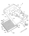
- FIG. 2 is a schematic diagram of the target unit.
- the target unit 5 has two target panels 11 ⁇ / b> A and 11 ⁇ / b> B in a proton beam 6 in a V shape so that the front end surface 11 b on the front end side (incident direction side of the proton beam 6) is aligned.
- Inclined with respect to the axial line for example, 30 degrees, and attached to the distal end flange portion 10a of the collimator 10 provided at the distal end portion of the beam conduit 4 with an insulating member 113 for electrical insulation interposed therebetween.
- the side plates 12L and 12R are assembled from the left and right sides in FIG. 2 in a watertight manner with the insulating members 124 for electrical insulation interposed between the left and right panel side surfaces 11cL and 11cR of the target panels 11A and 11B, and are in contact with the tip flange portion 10a.
- a cylindrical casing with a bottom from the outside is assembled to the front end flange portion 10a with a seal member interposed therebetween so that the inside of the casing is airtight, for example, by screw fixing. (See FIG. 5 of Patent Document 3).
- the beam stop member 112 is fixed to the front end surfaces 11b and 11b by, for example, screw fixing so that the proton beam 6 does not pass as shown by the phantom line (two-dot chain line).
- the beam stop member 112 is a structure for stopping the proton beam 6 so as not to irradiate the casing when the proton beam 6 is irradiated to the gap between the tip surfaces 11b and 11b.
- the beam stop member 112 for example, low carbon steel is used.
- the coolant channel holes 117L and 117L are provided on the left side surfaces of the target panels 11A and 11B in FIG. 2, and the coolant channel holes 117R and 117R are provided on the right side surfaces of the target panels 11A and 11B, although not shown. ing.
- the coolant channel holes 117L and 117L correspond to the coolant channel holes 121L and 121L at two locations on the upper and lower sides of the side plate 12L, and a watertight seal material (not shown) is arranged so that the coolant does not leak.
- the coolant communication hole 122L leads to the coolant passage hole 123L on the upper surface.
- the coolant channel hole 123L and the first coolant channel hole (not shown) provided in the tip flange portion 10a are the first coolant pipe (not shown).
- the first coolant pipe is, for example, a pipe having a resin tube resistant to neutron irradiation and a watertight metal connector at both ends thereof.
- the metal connector on one side of the first coolant pipe is connected to the first coolant channel hole so that the coolant flows through the coolant channel of the collimator 10 (see Patent Document 3). Fig. 5).
- the metal connector on the other side of the first coolant pipe is connected to the coolant channel hole 123L.
- coolant channel holes 117R, 117R correspond to the coolant channel holes 121R, 121R at two locations on the upper and lower sides of the side plate 12R and are not shown in the figure. Is arranged so that the coolant does not leak, and the coolant communication hole 122R is connected to the coolant passage hole 123R on the upper surface.
- the coolant channel hole 123R and the second coolant channel hole (not shown) provided in the tip flange portion 10a are the second coolant pipe (not shown). Connected by The second coolant pipe has the same configuration as the first cooling pipe.
- the metal connector on one side of the second coolant pipe is connected to the second coolant channel hole so that the coolant flows through the coolant channel of the collimator 10 (see Patent Document 3). Fig. 5).
- the metal connector on the other side of the second coolant pipe is connected to the coolant channel hole 123R.
- one of the first and second cooling pipes supplies coolant to the target panels 11A and 11B, and the other of the first and second cooling pipes supplies coolant discharged from the target panels 11A and 11B. Then, it is discharged through the cooling passage of the collimator 10.
- pure water is used as the coolant.
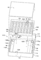
- FIG. 3 is an explanatory diagram of a target panel mounting structure.
- FIG. 4 is an explanatory diagram of an exploded structure on the beam irradiation surface 11a side of the target panel 11A.
- 3 illustrates the target panel 11A in FIG. 2 as an example, but the mounting structure of the target panel 11B is the same.
- the mounting bolt 17 is screwed into the female screw hole (not shown) provided in the front end surface of the front end flange portion 10a through the insertion hole 115 and the insulating piece 18 for electrical insulation, and the target panel 11A is preliminarily formed.
- 11B and the side plates 12L and 12R are assembled to the tip flange portion 10a. Due to the insulating piece 18, the mounting bolt 17 does not come into contact with the target panels 11A and 11B.
- the target 51A is fixed to the beam irradiation surface 11a that is the surface (front side) of the target panels 11A and 11B on which the proton beam 6 is irradiated. They are shown separately for easy understanding.
- the target 51 ⁇ / b> A includes a metal substrate 52 ⁇ / b> A, a target material 54 (see FIGS. 4 and 5), a sealing metal thin film 53, and a back plate 55.
- the back board 55 is a part of target panel 11A, 11B (refer FIG. 4).
- carbon steel and copper are conceivable as members of the target panels 11A and 11B.
- the kind of the constituent member of the sealing metal thin film 53 is a material that can prevent a chemical reaction such as oxidation of the target material 54, is hardly corroded by the target material 54, and has little loss of the proton beam 6 or less heat generation by the proton beam 6. Therefore, it is preferable to select the type of component that allows the proton beam 6 to pass through.
- a specific constituent member of the sealing metal thin film 53 any one of a stainless steel thin plate, a titanium thin plate, a titanium alloy thin plate, a beryllium thin plate, and a beryllium alloy thin plate is appropriate.
- a stainless foil having a thickness of 4 ⁇ m is used from the viewpoint of low manufacturing cost.
- the thickness is 5 ⁇ m
- a beryllium alloy thin plate is used, The thickness is preferably 10 ⁇ m.
- the back surface of the metal substrate 52A there is a coolant channel 52d configured by cutting a groove as shown in FIGS. 3, 4, and 5, and the back surface of the metal substrate 52A has a target panel as shown in FIG. It is joined to the back plate 55 of the beam irradiation surface 11a of 11A.
- the back plate 55 is provided as a concave portion with a slight step from the surface of the beam irradiation surface 11a.
- the coolant is supplied to or gathered from the coolant channel 52d near the left and right sides of the back plate 55.
- Manifolds 116L and 116R are provided so as to be dented toward the front side.
- the coolant channel hole 116La that opens to the manifold 116L communicates with the coolant channel hole 117L.
- the coolant channel hole 116Ra opened to the manifold 116R communicates with the coolant channel hole 117R.
- This structure is also the same for the target panel 11B, except that the left and right signs are opposite to those in FIG. 4, and the shape is exactly the same.
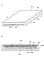
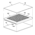
- FIG. 5 is an exploded view for explaining the target.
- the back plate 55 is simplified and schematically shown in a flat plate shape.
- the manifolds 116L and 116R are located on the lower side like the back plate 55 of the target panel 11A (11B). It is a groove recessed in.
- an edge frame portion 52a is provided on the outer peripheral side of the substantially rectangular plate-shaped metal substrate 52A (indicated as “holding surface X” in FIG. 5), and is surrounded by the edge frame portion 52a.
- the recessed portion 52c On the inner side, it is a region of the recessed portion 52c that is thinned leaving the island portions 52b regularly and discretely arranged in the left-right direction and the front-rear direction in FIG.
- the surface height of the edge frame portion 52a and the surface height of the island portion 52b are the same, and the level difference from the recess 52c is the same as the thickness of the lithium metal (Li) that is the target material, for example, 50 ⁇ m.
- the formation of the recess 52c leaving the island portion 52b constitutes a so-called “embossed structure”. Such processing can be performed by, for example, milling, but can also be performed by electrical discharge processing or chemical etching.
- a coolant channel 52d is formed by grooving, and the remaining portions become the cooling fins 52e.
- the recess 52c is filled with metallic lithium, and thereafter, the metal substrate 52A is placed on the back plate 55 shown in FIG. 4 so that the back surface of the metal substrate 52A is opposed to the concave portion 52c. 53, and the sealing metal thin film 53 is bonded to the surface of the edge frame portion 52a and the surface of the island portion 52b by HIP processing, and the back surface of the metal substrate 52A and the back plate 55 are bonded simultaneously.
- the thickness of the lithium metal (Li) as the target material is 50 ⁇ m, but the target panels 11A and 11B are set at an inclination of 30 ° with respect to the irradiation direction of the proton beam 6, so that the proton beam
- the passing distance of the target material 54 of No. 6 is about 110 ⁇ m, which is a sufficient thickness.
- the proton beam 6 with energy of 2.8 MeV drops to less than 1.889 MeV while passing this distance through the lithium metal (target material 54)
- the proton will pass through the metal substrate 52A. It can suppress that the irradiated proton produces inelastic scattering with lithium and emits ⁇ rays.
- the metal substrate 52A is preferably low carbon steel (Fe) or tantalum (Ta), and the thickness from the bottom surface of the recess 52c to the groove bottom of the coolant channel 52d is determined by the proton beam 6 incident on the target material 54. The thickness is such that all remaining protons that have passed through the target material 54 can be blocked.
- Iron is a low-cost material in addition to being as good in resistance to blistering due to lattice defects caused by proton collisions (blistering) and hydrogen embrittlement as tantalum (Ta).
- copper (Cu) is preferable because of its thermal conductivity, but carbon steel may be used in consideration of bonding by metal substrate 52A and HIP (Hot Isostatic Pressing) bonding. .
- FIG. 6 is an explanatory diagram of the manufacturing process of the target 51A.
- FIG. 6A shows an emboss structure processing process for forming an emboss structure on the holding surface side X (front side) of the metal substrate 52A of the target 51A, and the metal substrate.
- an adhesion promotion layer forming step for forming an adhesion promotion layer on the bottom surface of the recess 52c is performed.
- the explanatory diagram of the target material filling step of filling the melted target material into the recess 52c is a state explanatory diagram after the completion of the target material filling step, (c), State explanatory diagram after the holding surface side smoothing step is finished, (d) is a state explanation after completion of the joining step of HIP joining the sealed metal thin film 53, the metal substrate 52A and the back plate 55 after the target material filling step.
- the target 51A is manufactured as follows. (1) Coolant flow path formation processing step One side of the rectangular low carbon steel or tantalum plate that is the base of the metal substrate 52A (the back side (corresponding to the lower side in FIG. 6A)) In order to form the coolant channel 52d by milling or the like, a large number of grooves are formed and cooling fins 52e are provided (see FIG. 6A).
- Adhesion promoting layer forming step Next to the embossed structure processing step, an ultrathin layer (adhesion promoting layer) of copper, aluminum, magnesium, or zinc is formed on the bottom of the recess 52c, for example, a film forming process such as vapor deposition or sputtering. And the thickness thereof is, for example, 0.05 ⁇ m.
- This is a process for improving the adhesion (wetting property) between lithium as the target material 54 and the metal substrate 52A.
- the film forming process such as vapor deposition and sputtering
- the upper surface in FIG. 6A of the edge frame portion 52a and the island portion 52b is subjected to a masking process so as not to form a very thin layer of copper, The masking is removed after the film formation process such as vapor deposition and sputtering.
- a molten lithium metal as the target material 54 contained in the crucible 61 is poured into the recess 52c in an argon gas atmosphere or in vacuum (see FIGS. 6A and 6B). ). Since argon gas contains oxygen and moisture (H 2 O) as impurities, the molten lithium metal is oxidized, so it is preferable to fill it in vacuum.
- the lithium metal which is the target material 54 filled in the recess 52c in the (4) target material filling step is solidified as it is in argon gas or in vacuum.
- Lithium metal adheres to the surfaces of the edge frame portion 52a and the island portion 52b, and further rises from the surfaces of the edge frame portion 52a and the island portion 52b. Therefore, in an argon gas atmosphere or in a vacuum, this is scraped to the height of the surface of the edge frame portion 52a and the island portion 52b, for example, by milling, and the lithium metal powder is also removed by blowing argon gas or the like.
- the surfaces of the edge frame portion 52a and the island portion 52b are exposed in a clean state, and only the concave portion 52c is filled with lithium metal (see FIG. 6C). Since argon gas contains oxygen and moisture (H 2 O) as impurities, the molten lithium metal is oxidized, so it is preferable to grind in vacuum.
- the back plate 55 of the target panel 11A (or the target panel 11B) (in FIG. 6D, the back plate 55 is a rectangular flat plate for the sake of explanation.
- the metal substrate 52A is placed on the back plate 55 with the back side of the metal substrate 52A facing down, and then the sealing metal is placed on the holding surface side X (see FIG. 5) of the metal substrate 52A.
- a thin film 53 is placed.
- a contact member that is not bonded to the sealed metal thin film 53 and has a flat bottom surface facing the sealed metal thin film 53 is placed on the sealed metal thin film 53 during HIP bonding.
- the contact member for example, ceramic can be considered.
- This abutting member has a moderate weight, and removes argon gas between the sealing metal thin film 53 and the holding surface side X surface of the metal substrate 52A before starting the HIP bonding, and also HIP bonding.
- the sealing metal thin film 53 is kept flat in contact with the holding surface side X surface of the metal substrate 52A so that the lithium metal melts and the sealing metal thin film 53 does not sink into the recess 52c. belongs to.
- HIP bonding is performed.
- the sealed metal thin film 53 and the surfaces of the edge frame portion 52a and the island portion 52b of the metal substrate 52A can be joined, and the metal substrate 52A and the back plate 55 can be joined simultaneously.
- the four side surfaces of the metal substrate 52A are formed on the beam irradiation surface 11a of the target panel 11A (or the target panel 11B).
- the manifolds 116L and 116R are hermetically bonded to the water-tight structure on the beam irradiation surface 11a side of the target panel 11A (or target panel 11B). Thereby, it is possible to omit the processing steps as compared with the case where the sealing metal thin film 53 is bonded to the surface of the edge frame portion 52a and the island portion 52b of the metal substrate 52A and the metal substrate 52A and the back plate 55 are bonded separately. Can do. Thus, the target 51A is completed.
- FIG. 7A and 7B are explanatory diagrams of the structure of the target 51B of the comparative example, where FIG. 7A is a perspective view of the target 51B, and FIG. 7B is a YY sectional view of FIG.
- the target 51B of the comparative example on the surface side of the metal substrate 52B, an edge frame portion 52a is provided on the outer peripheral side, and a uniformly thinned recess 52c region is provided on the inner side surrounded by the edge frame portion 52a.
- the target material 54 has a structure in which pure lithium metal is sealed in the recess 52c that does not have the embossed structure.
- the sealed metal thin film 53 on the metal substrate 52A on the holding surface side X on which the proton beam 6 is incident is bonded to the surfaces of the edge frame portion 52a and the island portion 52b of the metal substrate 52A. Therefore, as shown in the comparative example, the lithium metal of the target material 54 is heated by the proton beam 6 as compared with the case where the holding surface side X on which the proton beam 6 of the metal substrate 52B is incident does not have an embossed structure. Even in the molten state, the swelling due to the thermal expansion of the sealed metal thin film 53 is suppressed, and it is possible to suppress the occurrence of a bias due to gravity on one side of the flat surface inside the edge frame portion 52a of the molten lithium metal.
- the proton beam 6 is shaped so that the collimator 10 uniformly strikes the target material 54 of the target panels 11A and 11B with the collimator 10, and therefore a part of the sealed metal thin film 53 of the target 51A. It is possible to prevent the proton beam 6 from being irradiated in a spot shape only, and to prevent the sealing metal thin film 53 from being damaged by overheating. As a result, the time until the end of the life is reached due to the irradiation deterioration of the sealing metal thin film 53, and the life of the target 51A is extended.
- the molten lithium metal is biased by gravity on one side of the plane inside the edge frame portion 52a. Will occur. As a result, a portion where the molten lithium metal is not in contact with the back side of the sealing metal thin film 53 is generated, and the portion is not cooled through the molten lithium metal, and the time until the sealing metal thin film 53 is damaged due to overheating. And the life of the target 51B is shortened.
- the target 51A of the present embodiment since this is not the case, the lifetime is longer than that of the target 51B of the comparative example, which is useful for reducing the cost per patient in the boron capture therapy.
- the thickness of the lithium metal of the target material 54 is as thin as 50 ⁇ m, the proton beam 6 is suppressed from losing its energy in the lithium metal due to inelastic scattering with lithium, and inelastically scattered ⁇ rays. Can be reduced. As a result, the structural weight of the ⁇ -ray shielding of the irradiation unit 2 can be reduced and reduced, and the irradiation unit 2 can be downsized.
- the circulation piping structure becomes complicated, and the circulation piping that is piped outside the irradiation unit 2 While a ⁇ -ray shielding structure is required, the present embodiment does not require this and the configuration of the target unit 5 can be made compact.
- the metal substrate 52A is made of low carbon steel or tantalum, the swelling phenomenon (blistering) due to absorption of protons (hydrogen) is suppressed more than when the metal substrate 52A is made of copper (Cu), and the life of the target 51A is shortened. It will also help to reduce per-patient costs in boron capture therapy.
- the embossed structure may be either a regular structure or an irregular structure, and the shape of the thinned recess and the remaining island part.
- the shape may be configured by either a straight line or a curved line.
- a concave portion reduced in a lattice pattern in plan view is formed on a metal substrate surface so that rectangular island portions are arranged at equal intervals in the front-rear direction and the left-right direction.
- the island portions 52b are arranged in the “front and rear direction” rows adjacent to the left and right in the same “front and rear” position, but are not limited thereto.
- the islands 52b may be arranged in a row in the front-rear direction adjacent to the left and right, not in the same front-rear position, but in a shifted “staggered” shape.
- FIG. 8 is an explanatory diagram of a configuration of a modified target 51C, in which (a) is a schematic perspective view and (b) is a ZZ cross-sectional view in (a).
- FIG. 9 is an explanatory diagram of an exploded structure on the beam irradiation surface 11a side of the target panel in the modification.
- FIG. 10 is an explanatory diagram of an arrangement structure of a molten lithium inlet and a full molten lithium outlet of a target panel in a modified example.
- the same components as those of the target 51A are denoted by the same reference numerals, and redundant description is omitted.
- the target 51C schematically shows the metal substrate 52C in a flat plate shape, the sealing metal thin film 53 is bonded to the holding surface X side of the metal substrate 52C, and the opposite side of the holding surface X of the metal substrate 52C.
- a back plate 55 is joined.
- the target 51C is different from the target 51A in that (1) as shown in FIG. 8, a slightly wide rectangular planar recess 52c1 without islands 52b at two locations near the diagonal corners on the holding surface X side of the metal substrate 52C. , 52c2 and (2) an injection passage 63 that communicates with the recess 52c1 and, for example, a cylindrical protrusion on the opposite side of the holding surface X of the metal substrate 52C.
- the through-holes 52f1 and 52f2 of the metal substrate 52C are inserted into through-holes 120A and 120B that penetrate the flat surface of the back plate 55 at positions avoiding the manifolds 116L and 116R on the left and right inner sides as shown in FIGS.
- the back plate 55 (target panel 11A) is configured to be flush with the surface on the opposite side of the holding surface X, and the injection passages 63 and 64 open to the surface on the opposite side of the holding surface X of the target panel 11A.
- the target panel 11B has the same configuration.
- a molten lithium injection pipe 65 indicated by a virtual line is provided in the injection passage 63 as shown in FIG.
- a filled molten lithium outlet pipe 66 indicated by a virtual line two-dot chain line.
- the molten lithium injection pipe 65 and the molten lithium outlet pipe 66 are cut and cut to remove the solidified lithium metal in the injection passages 63 and 64,
- the injection passages 63 and 64 of the through portions 52f1 and 52f2 are sealed and welded by a lid (not shown).
- the target 51C is manufactured as follows.
- Coolant flow path forming process For the rectangular low-carbon steel or tantalum plate material used as the base of the metal substrate 52C, milling is performed on one side (back side (corresponding to the upper side in FIG. 10)).
- cooling fins 52e are provided (see FIG. 10).
- Injection passage drilling step Thereafter, holes in the injection passages 63 and 64 are drilled in the vicinity of the lower right corner and the upper left corner of the metal substrate 52C in FIG.
- the edge frame portion 52a and the inner side surrounded by the edge frame portion 52a are arranged in the left-right direction and the front-rear direction in FIG.
- the recesses 52c are thinned to a predetermined depth while leaving a plurality of discretely arranged islands 52b, for example, 50 ⁇ m thinning, the same as the thickness of lithium metal (Li) as a target material For example, by milling.
- a 50 ⁇ m thinning recess 52c1 is formed in the vicinity of the lower left corner in FIG. 9 so as to protrude toward the lower edge frame 52a in FIG.
- the meat processing recess 52c2 is formed so as to protrude toward the upper edge frame 52a in FIG.
- the holes of the injection passages 63 and 64 drilled in the injection passage drilling process are opened on the bottom surfaces of the recesses 52c1 and 52c2, respectively.
- the back plate 55 of the target panel 11A (or the target panel 11B) (in FIG. 8, the back plate 55 is schematically shown as a rectangular flat plate for explanation).
- the back plate 55 With the back side of the metal substrate 52C facing down, and then the metal is sealed on the holding surface side X (see FIG. 8A) of the metal substrate 52C.
- a thin film 53 is placed.
- the through portions 52f1 and 52f2 are inserted into the through holes 120A and 120B of the back plate 55 (see FIGS. 9 and 10) of the target panel 11A (or the target panel 11B), respectively, and the through portions 52f1 and 52f2 are inserted.
- the end surface is flush with the surface opposite to the holding surface X side of the back plate 55 of the target panel 11A (or target panel 11B).
- a contact member that is not bonded to the sealed metal thin film 53 and has a flat bottom surface facing the sealed metal thin film 53 during HIP bonding is placed on the sealed metal thin film 53.
- the contact member for example, ceramic can be considered.
- This abutting member has a moderate weight, and removes argon gas between the sealing metal thin film 53 and the holding surface side X surface of the metal substrate 52C before starting the HIP bonding, and also HIP bonding.
- the sealing metal thin film 53 is kept flat in contact with the holding surface side X surface of the metal substrate 52C so that the sealing metal thin film 53 does not sink into the recesses 52c, 52c1, 52c2. It is.
- HIP bonding is performed.
- the sealed metal thin film 53 and the surfaces of the edge frame portion 52a and the island portion 52b of the metal substrate 52C can be joined, and the metal substrate 52C and the back plate 55 can be joined simultaneously.
- the through portions 52f1 and 52f2 and the through holes 120A and 120B of the back plate 55 are joined.
- the side surfaces of the four sides of the metal substrate 52C are also joined simultaneously with the edge forming the back plate 55 of the beam irradiation surface 11a of the target panel 11A (or target panel 11B), so that the target panel 11A (or target panel) On the beam irradiation surface 11a side of 11B), the manifolds 116L and 116R are hermetically joined in a watertight structure.
- the sealing metal thin film 53 is bonded to the surface of the edge frame portion 52a and the island portion 52b of the metal substrate 52C and the metal substrate 52C and the back plate 55 are bonded separately. Can do.
- the molten lithium injection pipe 65 is respectively provided on the end surfaces of the through portions 52f1 and 52f2 exposed on the side opposite to the holding surface X side of the back plate 55 of the target panel 11A (or target panel 11B). Is welded to one end side of the molten lithium outlet pipe 66. Then, the other end side of the molten lithium outlet pipe 66 is connected to a vacuum pump such as an oil diffusion pump, and the other end side of the molten lithium injection pipe 65 is connected to the molten lithium metal supply side.
- the target panel 11A (or the target panel 11B) is preferably installed in a sealed container having a heating means such as induction heating, a cutting device, a welding device, and the like.
- the molten lithium outlet pipe 66 side is placed on the upper side, the molten lithium injection pipe 65 side is placed on the lower side, the vacuum pump is operated, The space of the recesses 52c, 52c1, 52c2 formed between the back plate 55 and the sealed metal thin film 53 and the inside of the molten lithium outlet pipe 66 are evacuated. Further, the target panel 11A (or the target panel 11B) is heated to 200 ° C. or higher, for example, a first predetermined temperature of 400 to 500 ° C. by a method such as induction heating.
- a plurality of temperature sensors are attached to the target panel 11A (or the target panel 11B), and it is confirmed in advance by a signal from the temperature sensor that heating has been completed to the first predetermined temperature.
- Molten lithium metal which is the target material 54 heated to 200 ° C. or higher, is injected through the molten lithium injection pipe 65 so as to fill the spaces of the recesses 52c, 52c1, and 52c2.
- the first predetermined temperature described above is a temperature at which the molten lithium metal does not erode the back plate 55 and the sealing metal thin film 53 even if it is high, and is determined experimentally in advance.
- the first predetermined temperature may be the same temperature as the second predetermined temperature.
- Target Material Injection Passage Blocking Process Next, the closing process of the injection paths 63 and 64 after filling with molten lithium metal will be described. After the holding time has elapsed, the spaces in the recesses 52c, 52c1, and 52c2 are gradually cooled while being filled with the molten lithium metal, and the spaces in the recesses 52c, 52c1, and 52c2 are filled with solid lithium metal. After confirming that the cooling is sufficiently completed by the temperature sensor attached to the target panel 11A (or the target panel 11B), the molten lithium outlet pipe 66 is closed to stop the vacuum pump, and the target panel 11A (or the target panel 11B). ) Is placed in an argon gas atmosphere or in a vacuum state.
- the molten lithium injection pipe 65 and the molten lithium outlet pipe 66 are cut by the cutting tool described above, and the lithium metal in the injection passage 63 of the through portion 52f1 and the injection passage 64 of the through portion 52f2 is cut and removed.
- a lid (not shown) made of the same member as the metal substrate 52C (not shown) prepared in advance in the sealed container is fitted into the injection passages 63 and 64 of the through portions 52f1 and 52f2, and laser welding, electron beam welding, or the like is performed. Seal and weld. Thus, the target 51C is completed.
- the molten lithium outlet pipe 66 and the molten lithium outlet pipe 66 are cut and cut to cover the injection passages 63 and 64. It is not limited to that.
- the molten lithium metal or the solid lithium metal may be pressed and sealed and welded in a state where the molten lithium outlet pipe 66 and the molten lithium outlet pipe 66 are filled.
- the metal substrate 52C is provided with the through portions 52f1 and 52f2.
- the present invention is not limited thereto, and the through portions 52f1 and 52f2 are not provided, and the holes of the injection passages 63 and 64 of the metal substrate 52C are provided.
- the edges of the through holes 120A and 120B of the back plate 55 may be HIP-bonded, and the through holes 120A and 120B may constitute part of the injection passages 63 and 64, respectively.
- the filled target material 54 is melted during HIP bonding and becomes a high temperature, and the metal substrate 52A and the sealed metal thin film 53 are formed. This has the effect of preventing the possibility of erosion. As a result, the target 51C of the present modification can have a longer lifetime than the target 51A of the embodiment.
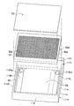
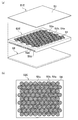
- FIG. 11 is a structural explanatory view of a modified target 51D
- (a) is an exploded explanatory view of the target 51D
- (b) is a plan view of a metal substrate 52D on which the target material 54 is held
- c) is an enlarged perspective view of an emboss structure in the metal substrate 52D.
- the same components as those of the target 51A are denoted by the same reference numerals, and redundant description is omitted.
- the target 51D includes a metal substrate 52D, a target material 54, a sealing metal thin film 53, and a back plate 55.
- the back plate 55 is simplified and schematically shown in a flat plate shape in FIG. 11A, but is a part of the target panels 11A and 11B as in the target 51A.
- the portions of the manifolds 116L and 116R are grooves that are recessed downward.
- the metal substrate 52D has a substantially rectangular plate shape, and an edge frame portion 52a is provided on the outer peripheral side on the surface side (upper side in FIG. 11A).
- the metal substrate 52D has an area of a recessed portion 52c that is thinned leaving an island portion 52b that is regularly and discretely arranged in the left-right direction and the front-rear direction on the inner side surrounded by the edge frame portion 52a.
- the target material 54 is held in the recess 52c.
- the target 51D is different from the target 51A in the shape of the embossed structure formed on the holding surface of the metal substrate 52D.
- the embossed structure of the metal substrate 52D has a plurality of circular recesses arranged at equal intervals so as to be arranged in a hexagonal manner and a plurality of recesses communicating with each other. It has a shape regularly arranged so as to leave the portion 52b.
- the target material 54 is held in the regularly arranged recesses.
- FIG. 11C is an enlarged perspective view of a part of the embossed structure in a state where the target material 54 is not filled.
- the metal substrate 52D has a concave portion formed by repetition of a circular concave portion 52c3 thinned into a circular shape in plan view and a rectangular communication concave portion 52c4 thinned so as to communicate with the adjacent circular concave portion 52c3.
- 52c is formed so as to leave an approximately hexagonal columnar island portion 52b at the apex position of the honeycomb structure.
- the material of the metal substrate 52D is preferably low carbon steel (Fe) or tantalum (Ta), and such an embossed structure can be processed by, for example, milling, but can also be performed by electric discharge machining or chemical etching.
- the circular recess 52c3 and the communication recess 52c4 can be formed to have the same depth.
- the surface height of the edge frame 52a and the surface height of the island 52b are the same, and the step between the recess 52c is the target material. It is the same as the thickness of the lithium metal (Li) which is, for example, 50 ⁇ m.
- the concave portion 52c formed by the circular concave portion 52c3 and the communication concave portion 52c4 has an area ratio of 70% or more in the inner area of the edge frame portion 52a of the metal substrate 52D so that the island portions 52b having a predetermined area are left discretely. It is preferable to form so that it becomes. By forming at such an area ratio, it is possible to avoid a reduction in the reaction cross-sectional area of the target material while securing the surface area of the island part joined to the sealing metal thin film.
- the circular recesses 52c3 are formed so that a plurality of circular shapes having a substantially circular shape and the same size or different sizes are regularly arranged. Can do.
- R indicates the radius of the circular recess 52c3
- D indicates the distance between the centers of the circular recesses 52c3.
- the radius R of the circular recess 52c3 is not particularly limited, but may be 1 mm to 5 mm, preferably 2 mm.
- the distance D between the centers of the circular recesses 52c3 is not particularly limited, but may be R + 1 mm to R + 3 mm, preferably R + 1 mm.
- the communication recess 52c4 is preferably a linear groove that communicates with each of the circular recesses 52c3.
- the communication recess 52c4 communicates with the shortest distance between the centers so that the axis line coincides with a line connecting the centers of the circular recesses 52c3. It can be arranged and provided so as to have a substantially rectangular shape in plan view.
- L1 indicates the width of the communication recess 52c4
- L2 indicates the length of the communication recess 52c4.
- the width L1 of the communication recess 52c4 is not particularly limited, but can be 1/5 to 1/2, preferably 1/2 of the radius of the circular recess 52c3.
- circular recesses 52c3 having a radius of 2 mm are arranged in hexagons at intervals of 5 mm, and adjacent circular recesses 52c3 are connected by communication recesses 52c4 of 1 mm square, an area ratio in the inner area of the edge frame 52a of the metal substrate 52D is secured by about 72%.
- the thickness from the bottom surface of the recess 52c to the groove bottom of the coolant channel 52d is set to a thickness that allows the proton beam 6 incident on the target material 54 to block all remaining protons that have passed through the target material 54.
- a coolant channel 52d is formed by grooving on the back surface side of the metal substrate 52D as in the target 51A, and the remaining portions are provided with cooling fins 52e. It is composed.
- the recess 52c is filled with metallic lithium, and then placed on the back plate 55 so that the back surface of the metal substrate 52D is opposed, and the sealing metal thin film 53 is placed on the upper surface of the metal substrate 52D, and sealed by HIP processing.
- the metal thin film 53 is bonded to the surface of the edge frame portion 52a and the surface of the island portion 52b, and the back surface of the metal substrate 52D and the back plate 55 are bonded simultaneously.
- Such a target 51D is manufactured according to the manufacturing method of the target 51A.
- the circular recess 52c3 disperses the pressure due to expansion, and the communication recess 52c4 is melted. Is distributed to the adjacent circular recesses 52c3 and leveled, the swelling of the sealing metal thin film is further suppressed as compared with the case of the target 51A of the embodiment, and the adhesion between the target material 54 and the sealing metal thin film is reduced. State is maintained. Therefore, the possibility of damage due to overheating of the sealed metal thin film can be further reduced.
- FIG. 12 is a structural explanatory view of a modified target 51E, (a) is an exploded explanatory view of the target 51E, and (b) is a plan view of the metal substrate 52E on which the target material 54 is held.
- the same components as those of the targets 51A and 51D are denoted by the same reference numerals, and redundant description is omitted.
- the target 51E includes a metal substrate 52E, a target material 54, a sealing metal thin film 53, and a back plate 55.
- the back plate 55 is simplified and schematically shown in a flat plate shape in FIG. 12A, but is a part of the target panels 11A and 11B as in the target 51A.
- the portions of the manifolds 116L and 116R are grooves that are recessed downward.
- the metal substrate 52E has a substantially rectangular plate shape, and on its surface side (upper side in FIG. 12A), an edge frame portion 52a is provided on the outer peripheral side. On the inner side surrounded by 52a, there is a region of a recess 52c that is thinned leaving an island 52b that is regularly and discretely arranged in the left-right direction and the front-rear direction.
- the target 51E has an embossed structure similar to that of the target 51D, and as shown in FIG. 12B, a hexagonal arrangement is adopted on the inner side surrounded by the edge frame portion 52a on the surface side of the metal substrate 52E.
- the concave portion 52c formed of the circular concave portion 52c3 thinned at equal intervals and the communication concave portion 52c4 thinned so as to communicate between the adjacent circular concave portions 52c3 leaves a substantially hexagonal columnar island portion 52b. In this way, the target material 54 is held.
- the target 51E is different from the target 51D in the material of the island part 52b in the emboss structure formed on the holding surface of the metal substrate 52E.
- the island portion 52b left by reducing the thickness of the recess 52c is made of the same material as that of the metal substrate 52D and is made of non-lithium metal, preferably made of low carbon steel (Fe) or tantalum (Ta).
- the island portion 52b is formed of a lithium alloy 54a that is also the target material 54.
- the island portion 52b is made of a lithium alloy, so that it has a function as a target and has a characteristic that it is difficult to melt by heating compared to the case of lithium.
- the lithium alloy examples include alloys that are heated and not melted by irradiation with a proton beam, that is, alloys having a melting point of about 300 ° C. or more, and a copper-lithium alloy, an aluminum-lithium alloy, and a magnesium-lithium alloy are preferable.
- a copper-lithium alloy, an aluminum-lithium alloy, and a magnesium-lithium alloy are preferable.
- Cu to be added is preferably 1% by mass or more, and more preferably 1 to 20% by mass.
- the added Al is preferably 20% by mass or more, and more preferably 20 to 40% by mass.
- Mg added is preferably 45% by mass or more, and more preferably 45 to 60% by mass.
- the effect in the target 51D is obtained, and the island portion 52b is formed of an alloy containing lithium as the target material 54. Therefore, also in the island portion 52b, neutrons are generated by irradiation with a proton beam. be able to. As a result, it is possible to reduce a decrease in neutron generation efficiency caused by forming the island portion 52b on the holding surface side of the metal substrate.
- a coolant channel 52d is formed by grooving on the back side of the metal substrate 52E, as in the target 51A, and the remaining portions are provided with cooling fins 52e. It is composed.
- the recess 52c is filled with metallic lithium, and then placed on the back plate 55 so that the back surface of the metal substrate 52E faces, and the sealing metal thin film 53 is placed on the holding surface side X of the metal substrate 52E.
- the sealed metal thin film 53 is bonded to the surface of the edge frame portion 52a and the surface of the island portion 52b by the HIP process, and the back surface of the metal substrate 52E and the back plate 55 are bonded simultaneously.
- FIG. 13 is an explanatory diagram of the manufacturing process of the target 51E.
- FIG. 13A is a process of reducing the thickness of the uniformly reduced recess 52c on the holding surface side (front side) of the metal substrate 52E0 of the target 51E. Forming an adhesion promoting layer on the bottom surface of the recess 52c after the step of forming and the coolant channel processing step of forming the groove for the coolant channel 52d on the opposite side (back side) of the holding surface of the metal substrate 52E0.
- the target 51E is manufactured as follows. (1) Coolant flow path forming processing step One side of the rectangular low carbon steel or tantalum plate that is the base of the metal substrate 52E (back side (corresponding to the lower side in FIG. 13A)) In order to form the coolant flow path 52d by milling or the like, a large number of grooves are formed and cooling fins 52e are provided (see FIG. 13A).
- Thinning processing step On the front side of the plate (corresponding to the upper side in FIG. 13 (a)), a thinning process of a predetermined depth is performed leaving the edge frame portion 52a, and a concave portion 52c having a flat bottom is formed. A metal substrate 52E0 is formed. For example, a thickness reduction process of 50 ⁇ m, which is the same as the thickness of lithium metal (Li) as a target material, is performed by milling.
- Adhesion promoting layer forming step Next to the thinning process step, a very thin layer (adhesion promoting layer) of copper, aluminum, magnesium, or zinc is formed on the bottom of the recess 52c, for example, a film forming process such as vapor deposition or sputtering. And the thickness thereof is, for example, 0.05 ⁇ m. This is a process for improving the adhesion (wetability) between the lithium alloy 54a and the metal substrate 52E0. At this time, before the film formation process such as vapor deposition and sputtering, the surface of the edge frame 52a is masked so as not to form an ultrathin copper layer, and the masking is removed after the film formation process such as vapor deposition and sputtering. .
- the lithium alloy 54a in a melted state is poured into the recess 52c of the metal substrate 52E0 (FIGS. 13 (a), ( b)). Since the argon gas contains oxygen and moisture (H 2 O) as impurities, the molten lithium alloy 54a is oxidized, so it is preferable to fill it in vacuum. The filled lithium alloy 54a is solidified as it is in argon gas or in vacuum.
- the lithium alloy 54a filled in the recess 52c is thinned to a predetermined depth that is circular in plan view, for example, the diameter is 4 mm and forms the bottom of the recess 52c. Thinning of the depth reaching the metal substrate is performed by milling or the like at a plurality of locations in the vertical and horizontal directions so as to adopt a hexagonal arrangement, thereby forming a circular recess 52c3. Also, the depth reaching the metal substrate that forms the bottom of the recess 52c so that the communication recess 52c4 having a predetermined shape is thinned so that the circular recesses 52c3 communicate with each other by, for example, a groove having a width of 1 mm.
- a metal substrate 52E having an embossed structure including a plurality of island portions 52b and recesses 52c made of a lithium alloy 54a is formed (see FIG. 13C). .
- Adhesion promoting layer forming step Next to the embossed structure processing step, an ultrathin layer (adhesion promoting layer) of copper, aluminum, magnesium, or zinc is formed on the bottom of the recess 52c, for example, a film forming process such as vapor deposition or sputtering. And the thickness thereof is, for example, 0.05 ⁇ m. This is a process for improving the adhesion (wetting property) between lithium as the target material 54 and the metal substrate 52E.
- the upper surface in FIG. 13C of the edge frame portion 52a and the island portion 52b is subjected to a masking process so as not to form a very thin layer of copper, The masking is removed after the film formation process such as vapor deposition and sputtering.
- Target material filling step Next, in the argon gas atmosphere or in vacuum, the lithium metal that is the target material 54 is melted and the material that is put in the crucible 61 is poured into the recess 52c (see FIG. 13D). . Since argon gas contains oxygen and moisture (H 2 O) as impurities, the molten lithium metal is oxidized, so it is preferable to fill it in vacuum. The lithium metal that is the filled target material 54 is solidified as it is in argon gas or in vacuum.
- FIG. 14 is an exploded explanatory diagram of a modified target 51F.
- the same components as those of the target 51A are denoted by the same reference numerals, and redundant description is omitted.
- the target 51F includes a metal substrate 52F, a target material 54, a sealing metal thin film 53, and a back plate 55.
- the back plate 55 is simplified and schematically shown in a flat plate shape in FIG. 13, but is a part of the target panels 11A and 11B as in the target 51A, and the target panel 11A (11B as shown in FIG. 4).
- the manifolds 116L and 116R are grooves that are recessed downward.
- the metal substrate 52F has a substantially rectangular plate shape, and on the surface side (the upper side in FIG. 14), an edge frame portion 52a is provided on the outer peripheral side, and the inner side surrounded by the edge frame portion 52a. , The region of the concave portion 52c that is uniformly thinned.
- the bottom of the recess 52c in the metal substrate 52F has a planar shape, and has a shape in which an embossed structure is not processed and formed as in the target 51B in the comparative example.
- the target 51F is different from the target 51B in the material of the target material 54 filled in the recess 52c.
- pure lithium metal consisting essentially of 100 mass% lithium is filled in the recess 52 c as the target material 54.
- the lithium alloy 54a is filled in the recess 52c as the target material 54.
- the lithium alloy 54a is a target material 54 having a characteristic that it is difficult to melt by heating as compared with lithium metal.
- the lithium alloy 54a for example, it is not heated and melted by irradiation with a proton beam, that is, the melting point is about 300 ° C.
- the added metal% is small so that the range of the proton beam in the lithium alloy is not shortened as much as possible.
- the lithium alloy include copper-lithium alloys, aluminum-lithium alloys, and magnesium-lithium alloys.
- the added Cu is preferably 1 to 20% by mass
- the added Al is preferably 20 to 40% by mass
- the added Mg is 45%. ⁇ 60% by weight is preferred.
- the material of the metal substrate 52F is preferably low carbon steel (Fe) or tantalum (Ta), and the recess 52c having a flat bottom can be processed by, for example, milling, but also by electric discharge processing or chemical etching. Yes.
- the step between the edge frame portion 52a and the recess 52c is the same as the thickness of the target material, for example, 50 ⁇ m.
- the thickness from the bottom surface of the recess 52c to the groove bottom of the coolant channel 52d is set to a thickness that allows the proton beam 6 incident on the target material 54 to block all remaining protons that have passed through the target material 54.
- a coolant channel 52d is formed by grooving on the back side of the metal substrate 52F as in the target 51A, and the remaining portions constitute cooling fins 52e. Yes.
- the recess 52c is filled with the lithium alloy 54a, and then the metal substrate 52D is placed on the back plate 55 so that the back surface of the metal substrate 52D is opposed, and the sealing metal thin film 53 is placed on the upper surface of the metal substrate 52F.
- the sealing metal thin film 53 is bonded to the surface of the edge frame portion 52a, and the back surface of the metal substrate 52F and the back plate 55 are bonded simultaneously.
- Such a target 51F is manufactured by filling the metal substrate 52E0 with the lithium alloy 54a, performing the holding surface side smoothing step, and then performing the bonding step by HIP in the above-described method of manufacturing the target 51E.
- a lithium alloy 54a that has been rolled to a required thickness is pressure-bonded to the sealed metal thin film 53, and this is placed on a metal substrate that is not provided with the recess 52c and further pressed, and the sealed metal thin film 53 and the metal substrate are bonded to the substrate.
- the target material 54 is heated and melted by irradiation with the proton beam, and the liquefied target material 54 is formed on the metal substrate. It can be prevented that the function as a target deteriorates due to uneven distribution in a part.
Landscapes
- Physics & Mathematics (AREA)
- Engineering & Computer Science (AREA)
- Chemical & Material Sciences (AREA)
- Chemical Kinetics & Catalysis (AREA)
- High Energy & Nuclear Physics (AREA)
- Optics & Photonics (AREA)
- Plasma & Fusion (AREA)
- Spectroscopy & Molecular Physics (AREA)
- Mechanical Engineering (AREA)
- Particle Accelerators (AREA)
- Radiation-Therapy Devices (AREA)
Abstract
Description
一般に、この目的の中性子発生装置のターゲット材としては、特許文献1,2に記載されているように7Li(p,n)7Be反応を利用するリチウム、9Be(p,n)反応を利用するベリリウム、高エネルギの陽子や重水素による核破砕反応を利用するウラン、タンタル、タングステン、鉛、ビスマス、水銀等の固体重金属が検討されている。
また、核破砕反応により発生する中性子のエネルギは極めて高く、ターゲット材を有するターゲットを内部に含み、ホウ素中性子捕獲療法において用いられる所用のエネルギの熱中性子や熱外中性子まで中性子のエネルギを減速させる減速材を有するとともに、高エネルギ中性子の漏洩を抑制する遮蔽材を有する大型の中性子照射部を必要とする。
然るに、陽子ビームをステンレス鋼薄板側からリチウム金属を保持するターゲットに照射すると、ステンレス鋼薄板が加熱されて膨れ上がる。ステンレス鋼薄板が膨れ上がり、リチウム金属とステンレス鋼薄板との接触がなくなるとステンレス鋼薄板が冷却されなくなり、ステンレス鋼薄板が破損してリチウム金属の密封性が損なわれる可能性がある。
金属基板の保持面側には、縁枠部と、縁枠部に囲まれた内部に縁枠部と同じ高さの複数の島部を残して、縁枠部及び複数の島部以外の他の領域をターゲット材の厚み分だけ減肉された凹部とするエンボス構造と、を有し、
ターゲット材が密封金属薄膜により金属基板の凹部に密封されることを特徴とする。
縁枠部に囲まれた内側に六方配置され、平面視で円形状を有する複数の円形凹部と、
隣接する円形凹部同士を互いに連通する連通凹部と、
からなることが好ましい。
また、金属基板は、保持面側と反対側の面側に冷却材を流す冷却材流路を多数条設けられていることが好ましい。
従って、金属基板が冷却材により冷却されることにより、金属基板、リチウムを介して密封金属薄膜も冷却され、密封金属薄膜の過熱による破損の可能性が低減できる。
本発明によれば、密封金属薄膜は、縁枠部及び複数の島部の表面とHIP接合され、金属基板の保持面側に接合されている。したがって、凹部に密封されたリチウム金属が陽子ビームの照射により加熱されて溶けても、密封金属薄膜の膨れ上がりによるターゲット材の厚さの変化が小さくなり、金属基板と密封金属薄膜との間で、ターゲットの縁枠部に囲まれた内側に均等に維持される。
前記ターゲット材が、1~20質量%のCu、20~40質量%のAl、または45~60質量%のMgのいずれかを含み、残部がLiと不可避不純物からなるリチウム合金で構成されることを特徴とする。
陽子ビーム発生装置1は、所定量の陽子(水素イオン)を発生させるイオン源1a、陽子を加速する加速器1bを含んでいる。
本実施形態における中性子発生装置100は、BNCT用のものであり、そのターゲット部5は、ターゲット材としてリチウム金属を用い、それに陽子を照射して7Li(p,n)7Be反応により中性子を発生させることとしている。そして、ターゲット材中でおこる7Li(p,n)7Be反応の閾値1.889MeV以上で3.0MeV程度までの陽子のエネルギの範囲で加速器1bにおいて可変に設定可能とする。そして、陽子ビーム6の電流値は、患者への中性子照射の治療時間がそれ程長くならない、例えば、30分程度を目標とし、15~20mA程度とする。
イオン源1aは、ここでは電子サイクロトロン共鳴減少を利用して水素(1H)のプラズマを生成し、ソレノイドコイル又は永久磁石と六極永久磁石によって水素(1H)プラズマを閉じ込め、水素(1H+)イオンを生成する。ECRイオン源は、無電極放電のための長時間連続安定運転が可能であり、大強度イオンビームを生成することができるという特徴がある。
コリメータ10は、ターゲット部5に入射する陽子ビーム6を、ターゲット部5のターゲット材54の配置されている領域に照射されるように絞り込む。コリメータ10は、内壁は、例えば、円筒形状をしており、その内壁の外側に図示しない水冷ジャッケットが配置されて、前記内壁が冷却される。
照射部2は、陽子ビーム6の軸方向に沿った外形がほぼ円柱形状をしており、ターゲット部5の前方に円柱形状の減速材21が配され、その周方向及び後方(陽子ビーム6の入射方向と反対方向)を反射材22が覆っている。ビーム導管4は反射材22の中央に設けられた貫通孔に挿通されている。反射材22の外周には、放射線遮蔽のための円筒状の中性子吸収材23が配されている。
減速材21及び反射材22の前方側(照射側)には、図示しないフィルタが配され、更にその前方に中央に開口が設けられたコリメータ24が配される。
中性子吸収材23としては、水素等の高速中性子を熱化し、中性子吸収時にγ線を放出しないような、例えば、ホウ素を含有したポリエチレン樹脂等が考えられる。
次に、図2~図6を参照しながらターゲット部5の構成を説明する。図2は、ターゲット部の概要図である。
図2及び図3に示すようにターゲット部5は、2枚のターゲットパネル11A,11Bを、その先端側(陽子ビーム6の入射方向側)の先端面11bを合わせるようにV字形に陽子ビーム6の軸線に対して傾斜させて、例えば、30度傾斜させて、ビーム導管4の先端部に設けられたコリメータ10の先端フランジ部10aに電気絶縁のための絶縁部材113を介在させて取り付けられる。更に図2における左右から側板12L,12Rをターゲットパネル11A,11Bの左右のパネル側面11cL,11cRに電気絶縁のための絶縁部材124を介在させて水密に組み付けるとともに、先端フランジ部10aに当接する。
そして、図2では省略してあるがその外側から有底の円筒形状のケーシングが、先端フランジ部10aに、ケーシング内が気密状態するようにシール部材を介在させて、例えば、ネジ固定により組み付けられる(特許文献3のFig.5参照)。
冷却材流路孔117L,117Lは、側板12Lの上下2箇所の冷却材流路孔121L,121Lと対応するようになっているとともに、図示しない水密シール材が配されて冷却材が漏れない構成とされて、冷却材連通孔122Lで上面の冷却材流路孔123Lにつながる。
前記した図示しないケーシング内で、冷却材流路孔123Rと先端フランジ部10aに設けられた第2の冷却材流路孔(図示せず)とが、第2の冷却材パイプ(図示せず)により接続される。その第2の冷却材パイプは、第1の冷却パイプと同一構成である。第2の冷却材パイプの一方側の金属コネクタは、第2の冷却材流路孔に接続されて、コリメータ10の冷却材流路を用いて冷却材を流通させるようにする(特許文献3のFig.5参照)。そして、第2の冷却材パイプの他方側の金属コネクタは、冷却材流路孔123Rに接続される。こうして、第1及び第2の冷却パイプの一方が、ターゲットパネル11A,11Bに冷却材供給をし、第1及び第2の冷却パイプの他方が、ターゲットパネル11A,11Bから排出される冷却材を、コリメータ10の冷却通路を介して排出する。
ここで、冷却材としては、例えば、純水を用いる。
先端フランジ部10aの先端面に設けられた雌ネジ孔(図示せず)に取り付けボルト17を、挿通孔115を通して、電気絶縁用の絶縁ピース18を介してネジ締めして、事前にターゲットパネル11A,11Bと側板12L,12Rが組み立てられたものが先端フランジ部10aに取り付けられる。絶縁ピース18により取り付けボルト17は、ターゲットパネル11A,11Bと接触することは無い。
密封金属薄膜53の構成部材の種類は、ターゲット材54の酸化等の化学反応を防止でき、又ターゲット材54により腐食され難い材質であるとともに、陽子ビーム6の損失や陽子ビーム6による発熱の少ないという要請から、陽子ビーム6を通過させやすい構成部材の種類を選ぶことが好適である。密封金属薄膜53の具体的な構成部材の例としては、ステンレス鋼薄板、チタン薄板、チタン合金薄板、ベリリウム薄板、ベリリウム合金薄板のいずれかが適当である。ここでは、密封金属薄膜53の例として、製造コストの安い観点から、厚さが4μmのステンレスフォイルとするが、チタン合金薄板を用いる場合は、厚さを5μm、ベリリウム合金薄板を用いる場合は、厚さを10μmとすることが好ましい。
この構造は、ターゲットパネル11Bについても同様であり、ただ左右を示す符号が図4と逆になるだけであり、形状としては全く同一である。
図5に示すようにほぼ矩形板形状の金属基板52Aの表面側(図5において「保持面X」と表示)には、外周側に縁枠部52aが設けられ、縁枠部52aで囲まれた内側において図6(a)における左右方向及び前後方向に規則的に離散的に配置された島部52bを残して減肉された凹部52cの領域となっている。縁枠部52aの表面高さと島部52bの表面高さが同じであり凹部52cとの段差は、ターゲット材であるリチウム金属(Li)の厚さと同じ、例えば、50μmである。この島部52bを残した凹部52cの形成は、いわゆる「エンボス構造」を構成している。このような加工は、例えば、フライス加工で行えるが、放電加工、薬品によるエッチング加工によっても行える。
そして、この凹部52cに金属リチウムが充填され、その後に、図4に示す裏板55上に金属基板52Aの裏面を対向させて載せ、更に金属基板52Aの保持面側Xの面に密封金属薄膜53を載せて、HIP加工により密封金属薄膜53を縁枠部52aの表面及び島部52bの表面に接合するとともに、金属基板52Aの裏面と裏板55とを同時に接合する。
鉄は、陽子の衝突の結果引き起こされる格子欠陥による膨れ現象(ブリスタリング)や水素脆化に対する耐性がタンタル(Ta)同様に良好であるのに加え、低価格な材料である。ターゲットパネル11A,11Bの素材としては、銅(Cu)がその熱伝導性から好ましいが、金属基板52AとHIP(Hot Isostatic Pressing :熱間静水圧プレス)接合による接合を考えると炭素鋼としても良い。
次に図6を参照しながらターゲット51Aの製造方法について説明する。図6は、ターゲット51Aの製造工程の説明図であり、(a)は、ターゲット51Aの金属基板52Aの保持面側X(表側)に、エンボス構造を形成するエンボス構造加工工程と、金属基板の保持面と反対側(裏側)に冷却材流路52d用の溝部を形成する冷却材流路加工工程との後に、凹部52cの底面に付着促進層を形成する付着促進層形成工程を行い、その後に、アルゴンガス雰囲気中又は真空中で、溶けたターゲット材を凹部52cに充填するターゲット材充填工程の説明図、(b)は、ターゲット材充填工程完了後の状態説明図、(c)は、保持面側平滑化工程を終了後の状態説明図、(d)は、ターゲット材充填工程後の、密封金属薄膜53と金属基板52Aと裏板55とをHIP接合した接合工程完了後の状態説明図である。
(1)冷却材流路形成加工工程
金属基板52Aの元になる矩形状の低炭素鋼又はタンタルの板材に対して、その1面側(裏側(図6(a)における下側面に対応))にフライス加工等によって冷却材流路52dを形成するために溝を多数加工し、冷却フィン52eを設ける(図6(a)参照)。
金属基板52Aの表側(図6(a)における上側面に対応)に、縁枠部52aと、縁枠部52aで囲まれた内側に、図6(a)における左右方向及び前後方向に規則的に離散的に配置された複数の島部52bとを残して凹部52cを所定の深さの減肉加工、例えば、ターゲット材であるリチウム金属(Li)の厚さと同じ、50μmの減肉加工を、例えば、フライス加工で行う。
エンボス構造加工工程の次に、凹部52cの底部に銅、アルミニウム、マグネシウム、又は亜鉛の極薄層(付着促進層)を、例えば、蒸着、スパッタリング等の成膜プロセスにより形成し、その厚さは、例えば、0.05μmとする。これは、ターゲット材54であるリチウムと金属基板と52Aとの付着性(ぬれ性)を良くするための加工である。この際、蒸着、スパッタリング等の成膜プロセスの前に縁枠部52aと島部52bの図6(a)における上側の表面には、銅の極薄層を形成しないようにマスキング処理をし、蒸着、スパッタリング等の成膜プロセス後にマスキングを剥がす。
次に、アルゴンガス雰囲気中又は真空中で、坩堝61に入っているターゲット材54であるリチウム金属の溶湯を凹部52cに流し込む(図6(a),(b)参照)。アルゴンガスは、不純物として酸素や水分(H2O)を含んでいるので、溶融したリチウム金属が酸化されるので、真空中で充填する方が好ましい。
次に、(4)ターゲット材充填工程において凹部52cに充填したターゲット材54であるリチウム金属は、アルゴンガス中又は真空中でそのまま凝固させるが、図6(b)に示すように、縁枠部52a及び島部52bの表面にもリチウム金属が付着し、更に、縁枠部52a及び島部52bの表面よりも盛り上がっている。
そこで、アルゴンガス雰囲気中又は真空中で、これを縁枠部52a及び島部52bの表面の高さまで、例えば、フライス加工により削り取り、リチウム金属の粉末もアルゴンガスのブロー等によって除去する。その結果、縁枠部52a及び島部52bの表面が清浄な状態で露出し、凹部52cにのみリチウム金属が充填された状態となる(図6(c)参照)。アルゴンガスは、不純物として酸素や水分(H2O)を含んでいるので、溶融したリチウム金属が酸化されるので、真空中で研削する方が好ましい。
次に、アルゴンガス雰囲気中で、ターゲットパネル11A(又は、ターゲットパネル11B)の裏板55(図6(d)では、模式的に説明のため裏板55を矩形状の平板で表示)を水平となるようにして、金属基板52Aの裏側を下にし、裏板55の上に載せ、次に、金属基板52Aの保持面側X(図5参照)の面上に密封金属薄膜53を載せる。
そしてHIP接合時に密封金属薄膜53と接合しない、且つ、密封金属薄膜53と対向する下面が平坦な当て部材を密封金属薄膜53の上に載せる。当て部材としては、例えば、セラミックが考えられる。
この当て部材は、重量的に適度な重量を有し、HIP接合を開始する前に密封金属薄膜53と金属基板52Aの保持面側Xの面との間のアルゴンガスを排除するとともに、HIP接合時に、密封金属薄膜53が平坦に金属基板52Aの保持面側Xの面に当接したままの状態を保ち、リチウム金属が溶けて、密封金属薄膜53が凹部52cに沈み込まないようにするためのものである。
このとき、金属基板52Aの冷却フィン52eの下面と裏板55とが接合されるだけでなく、金属基板52Aの四周の側面部もターゲットパネル11A(又は、ターゲットパネル11B)のビーム照射面11aの裏板55を形成する縁部とも同時に接合されるので、ターゲットパネル11A(又は、ターゲットパネル11B)のビーム照射面11a側は、マニフォールド116L,116Rが水密構造に密閉接合される。
これにより、密封金属薄膜53と金属基板52Aの縁枠部52a及び島部52bの表面との接合と、金属基板52Aと裏板55との接合と、を個別に行うよりも加工工程を省くことができる。
以上により、ターゲット51Aが完成する。
比較例のターゲット51Bは、金属基板52Bの表面側において、外周側に縁枠部52aが設けられ、縁枠部52aで囲まれた内側に一様に減肉された凹部52cの領域が設けられており、このエンボス構造を持っていない凹部52cに、ターゲット材54の純リチウム金属が密封された構造を有している。
本実施形態のターゲット51Aによれば、陽子ビーム6が入射する保持面側Xの金属基板52A上の密封金属薄膜53が、金属基板52Aの縁枠部52a及び島部52bの表面と接合されているので、比較例に示したように金属基板52Bの陽子ビーム6が入射する保持面側Xにエンボス構造を持っていない場合に較べて、ターゲット材54のリチウム金属が陽子ビーム6で加熱されて溶融状態になっても、密封金属薄膜53の熱膨張による膨らみが抑制され、溶融したリチウム金属の縁枠部52aの内部の平面の一方側に重力により偏りが発生するのを抑制できる。
これに対し、比較例では、コリメータ10を通して、ターゲット51Bのターゲット材54に均等に陽子ビーム6を照射しても、溶融したリチウム金属が縁枠部52aの内部の平面の一方側に重力により偏りが発生する。その結果、密封金属薄膜53の裏側に溶融したリチウム金属が接していない部分が発生し、その部分は溶融したリチウム金属を通して冷却されることが無く、過熱により密封金属薄膜53が破損するまでの時間が短くなり、ターゲット51Bの寿命が短くなる。
それに対し、本実施形態のターゲット51Aによれば、そういうことがないので、比較例のターゲット51Bよりも寿命が長くなり、ホウ素捕獲療法における患者一人当たりの費用の低減にも役立つ。
更に、ターゲット材54のリチウム金属を溶融状態で照射部2のターゲット部5に循環して使用する場合は、その循環配管構造が複雑となるとともに、照射部2の外に配管される循環配管のγ線遮蔽構造が必要になるのに対し、本実施形態ではその必要が無くコンパクトなターゲット部5の構成とできる。
次に、図8を参照しながら本実施形態におけるターゲット51Aとその製造方法の異なるターゲット51Cの構成とその製造方法について説明する。図8は、変形例のターゲット51Cの構成説明図であり、(a)は模式化して表示した斜視図、(b)は、(a)におけるZ-Z断面図である。図9は、変形例におけるターゲットパネルのビーム照射面11a側の分解構造説明図である。図10は、変形例におけるターゲットパネルの溶融リチウム注入口、充満溶融リチウム出口の配置構造の説明図である。ターゲット51Aと同じ構成については同じ符号を付し、重複する説明を省略する。
ターゲットパネル11Bについても同様の構成である。
そして、例えば、溶融リチウム金属の充填が完了して凝固した後に、溶融リチウム注入配管65、溶融リチウム出口配管66は切削切断されて、注入通路63,64内の凝固したリチウム金属を除去して、貫通部52f1,52f2の注入通路63,64は、図示しない蓋により密封溶接される。
(1)冷却材流路形成加工工程
金属基板52Cの元になる矩形状の低炭素鋼又はタンタルの板材に対して、その1面側(裏側(図10における上側面に対応))にフライス加工等によって冷却材流路52dを形成するために溝を多数加工し、冷却フィン52eを設ける(図10参照)。
(2)注入通路穿孔加工工程
その後、図10における金属基板52Cの右下隅近傍及び左上隅近傍に注入通路63,64の孔を穿孔する。
金属基板52Cの表側(図9における上側面に対応)に、縁枠部52aと、縁枠部52aで囲まれた内側に、図9における左右方向及び前後方向に規則的に離散的に配置された複数の島部52bとを残して凹部52cを所定の深さの減肉加工、例えば、ターゲット材であるリチウム金属(Li)の厚さと同じ、50μmの減肉加工を、例えば、フライス加工で行う。このとき、図9における左下隅近傍に50μmの減肉加工の凹部52c1を、図9における下側の縁枠部52a側に突出する形に形成するとともに、図9における右上隅近傍に50μmの減肉加工の凹部52c2を、図9における上側の縁枠部52a側に突出する形に形成する。
この結果、図9に示すように凹部52c1,52c2の底面には、それぞれ注入通路穿孔加工工程で穿孔した注入通路63,64の孔が開口している。
次いで、図10に示すように金属基板52Cの注入通路63,64の孔にそれぞれ連通する注入通路63,64の孔を有した円筒形状の貫通部52f1,52f2を溶接する。
次に、アルゴンガス雰囲気中で、ターゲットパネル11A(又は、ターゲットパネル11B)の裏板55(図8では、模式的に説明のため裏板55を矩形状の平板で表示)を水平となるようにして、金属基板52Cの裏側を下にし、裏板55の上に載せ、次に、金属基板52Cの保持面側X(図8(a)参照)の面上に密封金属薄膜53を載せる。
このとき、貫通部52f1,52f2は、それぞれターゲットパネル11A(又は、ターゲットパネル11B)の裏板55(図9、図10参照)の貫通孔120A,120Bに挿通されて、貫通部52f1,52f2の端面がターゲットパネル11A(又は、ターゲットパネル11B)の裏板55の保持面X側と反対側の面で面一となるようになっている。
この当て部材は、重量的に適度な重量を有し、HIP接合を開始する前に密封金属薄膜53と金属基板52Cの保持面側Xの面との間のアルゴンガスを排除するとともに、HIP接合時に、密封金属薄膜53が平坦に金属基板52Cの保持面側Xの面に当接したままの状態を保ち、密封金属薄膜53が凹部52c,52c1,52c2に沈み込まないようにするためのものである。
このとき、金属基板52Cの冷却フィン52eの下面と裏板55とが接合されるだけでなく、貫通部52f1,52f2と裏板55の貫通孔120A,120Bとも接合される。更に、金属基板52Cの四周の側面部もターゲットパネル11A(又は、ターゲットパネル11B)のビーム照射面11aの裏板55を形成する縁部とも同時に接合されるので、ターゲットパネル11A(又は、ターゲットパネル11B)のビーム照射面11a側は、マニフォールド116L,116Rが水密構造に密閉接合される。
これにより、密封金属薄膜53と金属基板52Cの縁枠部52a及び島部52bの表面との接合と、金属基板52Cと裏板55との接合と、を個別に行うよりも加工工程を省くことができる。
次に、ターゲットパネル11A(又は、ターゲットパネル11B)の裏板55の保持面X側と反対側に露出した貫通部52f1,52f2の端面に、それぞれ溶融リチウム注入配管65の一端側を溶接するとともに、溶融リチウム出口配管66の一端側を溶接する。そして、溶融リチウム出口配管66の他端側を、油拡散ポンプ等の真空ポンプに接続し、溶融リチウム注入配管65の他端側を溶融リチウム金属供給側に接続する。
このとき、ターゲットパネル11A(又は、ターゲットパネル11B)は、誘導加熱等の加熱手段、切削装置、溶接装置等を有した、密封容器内に設置することが好ましい。
十分に凹部52c,52c1,52c2の空間を溶融リチウム金属で満たすように注入した後は、溶融リチウム金属の供給側を閉じ、所定の時間、金属基板52C及び密封金属薄膜53と、溶融リチウム金属とが濡れあって十分に接触するまでターゲットパネル11A(又は、ターゲットパネル11B)の温度を、200℃以上の、例えば、200~300℃の第2の所定の温度に所定の時間(保持時間)保持する。この、第2の所定の温度及び保持時間は、予め実験的に定める。
次に、溶融リチウム金属を充填した後の注入通路63,64の閉塞加工工程について説明する。
保持時間経過後、凹部52c,52c1,52c2の空間を溶融リチウム金属が満たした状態のまま徐々に冷却して、凹部52c,52c1,52c2の空間が固体のリチウム金属が充填された状態となる。ターゲットパネル11A(又は、ターゲットパネル11B)に取り付けられた温度センサにより十分冷却が完了したことを確認後、溶融リチウム出口配管66を閉じて真空ポンプを停止し、ターゲットパネル11A(又は、ターゲットパネル11B)を設置した前記密封容器をアルゴンガス雰囲気又は真空状態とする。
そして、溶融リチウム注入配管65及び溶融リチウム出口配管66を前記した切削工具で切断し、貫通部52f1の注入通路63及び貫通部52f2の注入通路64内のリチウム金属を切削除去する。予め前記密封容器内に用意しておいた図示しない金属基板52Cと同一部材製の蓋(図示せず)を貫通部52f1,52f2の注入通路63,64に嵌め込み、レーザ溶接や電子線溶接等で密封溶接する。
以上により、ターゲット51Cが完成する。
また、本変形例において、(7)のターゲット材注入通路閉塞加工工程において、溶融リチウム出口配管66及び溶融リチウム出口配管66を切削切断して注入通路63,64に蓋をすることとしたが、それに限定されるものではない。溶融リチウム金属又は固体リチウム金属が溶融リチウム出口配管66及び溶融リチウム出口配管66内に充満している状態で、圧接して封印溶接しても良い。
次に、図11を参照しながら本実施形態におけるターゲット51Aとエンボス構造の異なるターゲット51Dの構成とその製造方法について説明する。図11は、変形例のターゲット51Dの構造説明図であり、(a)は、ターゲット51Dの分解説明図、(b)は、ターゲット材54が保持された金属基板52Dの平面図であり、(c)は、金属基板52Dにおけるエンボス構造の拡大斜視図である。ターゲット51Aと同じ構成については同じ符号を付し、重複する説明を省略する。
円形凹部52c3と連通凹部52c4が形成する凹部52cは、所定の面積の島部52bが離散して残されるように、金属基板52Dの縁枠部52aの内側面積における面積率が70%以上の範囲になるように形成することが好ましい。このような面積率で形成することにより、密封金属薄膜と接合される島部の表面積を確保しつつ、ターゲット材の反応断面積の縮小を避けることができる。
また、連通凹部52c4は、各円形凹部52c3を連通する直線状の溝とすることが好ましく、例えば、各円形凹部52c3の中心を結ぶ線に軸線が一致するように中心間の最短距離で連通する配置とし、平面視で略矩形状となるように設けることができる。図11(c)において、L1は連通凹部52c4の幅、L2は連通凹部52c4の長さを示す。連通凹部52c4の幅L1は、特に制限されるものではないが、円形凹部52c3の半径の1/5~1/2、好ましくは1/2とすることができる。
半径2mmの円形凹部52c3を5mm間隔で六方配置し、1mm四方の連通凹部52c4で隣接する円形凹部52c3を連通すると、金属基板52Dの縁枠部52aの内側面積における面積率は約72%確保される。
凹部52cの底面から冷却材流路52dの溝底までの厚さは、ターゲット材54に入射した陽子ビーム6がターゲット材54を通過した残りの陽子を全て阻止できる厚さとする。
凹部52cに金属リチウムが充填され、その後に、裏板55上に金属基板52Dの裏面が対向するように載せられ、更に金属基板52Dの上面に密封金属薄膜53が載せられて、HIP加工により密封金属薄膜53が縁枠部52aの表面及び島部52bの表面に接合されるとともに、金属基板52Dの裏面と裏板55とが同時に接合される構造となっている。
このようなターゲット51Dは、前記したターゲット51Aの製造方法に準じて製作される。
次に、図12を参照しながら変形例におけるターゲット51Dとエンボス構造の材質が異なるターゲット51Eの構成とその製造方法について説明する。図12は、変形例のターゲット51Eの構造説明図であり、(a)は、ターゲット51Eの分解説明図、(b)は、ターゲット材54が保持された金属基板52Eの平面図である。ターゲット51A,51Dと同じ構成については同じ符号を付し、重複する説明を省略する。
ターゲット51Dでは、凹部52cが減肉されることにより残される島部52bは、金属基板52Dと同一の材質であり、非リチウム金属で、好ましくは低炭素鋼(Fe)又はタンタル(Ta)で構成されている。これに対し、ターゲット51Eでは、島部52bは、ターゲット材54でもあるリチウム合金54aで形成される。島部52bは、材質がリチウム合金であることにより、ターゲットとしての機能を有し、且つ、リチウムの場合と比較して加熱により溶融し難い特性を有するものとなる。
銅-リチウム合金において、添加するCuとしては、1質量%以上が好ましく、1~20質量%がより好ましい。
アルミニウム-リチウム合金において、添加するAlとしては、20質量%以上が好ましく、20~40質量%がより好ましい。
マグネシウム-リチウム合金において、添加するMgとしては、45質量%以上が好ましく、45~60質量%がより好ましい。
凹部52cに金属リチウムが充填され、その後に、裏板55上に金属基板52Eの裏面が対向するように載せられ、更に金属基板52Eの保持面側Xの面に密封金属薄膜53が載せられて、HIP処理により密封金属薄膜53が縁枠部52aの表面及び島部52bの表面に接合されるとともに、金属基板52Eの裏面と裏板55とが同時に接合される構造となっている。
(1)冷却材流路形成加工工程
金属基板52Eの元になる矩形状の低炭素鋼又はタンタルの板材に対して、その1面側(裏側(図13(a)における下側面に対応))にフライス加工等によって冷却材流路52dを形成するために溝を多数加工し、冷却フィン52eを設ける(図13(a)参照)。
板材の表側(図13(a)における上側面に対応)に、縁枠部52aを残して所定の深さの減肉加工を行い、底部が平面状の凹部52cを有する金属基板52E0を形成する。例えば、ターゲット材であるリチウム金属(Li)の厚さと同じ、50μmの減肉加工を、フライス加工で行う。
減肉加工工程の次に、凹部52cの底部に銅、アルミニウム、マグネシウム、又は亜鉛の極薄層(付着促進層)を、例えば、蒸着、スパッタリング等の成膜プロセスにより形成し、その厚さは、例えば、0.05μmとする。これは、リチウム合金54aと金属基板52E0との付着性(ぬれ性)を良くするための加工である。この際、蒸着、スパッタリング等の成膜プロセスの前に縁枠部52aの表面には、銅の極薄層を形成しないようにマスキング処理をし、蒸着、スパッタリング等の成膜プロセス後にマスキングを剥がす。
次に、アルゴンガス雰囲気中又は真空中で、リチウム合金54aを溶かした状態で坩堝61にいれたものを金属基板52E0の凹部52cに流し込む(図13(a),(b)参照)。アルゴンガスは、不純物として酸素や水分(H2O)を含んでいるので、溶融したリチウム合金54aが酸化されるので、真空中で充填する方が好ましい。充填したリチウム合金54aは、アルゴンガス中又は真空中でそのまま凝固させる。
凝固したリチウム合金54aは、縁枠部52aの表面に付着し、更に、縁枠部52aの表面よりも盛り上がっているため、例えば、フライス加工により削り取り、リチウム合金54aの粉末もアルゴンガスのブロー等によって除去する(図13(b)参照)。アルゴンガスは、不純物として酸素や水分(H2O)を含んでいるので、溶融したリチウム金属が酸化されるので、真空中で研削する方が好ましい。
次に、凹部52cに充填したリチウム合金54aに、平面視で円形状となる所定の深さの減肉加工、例えば、直径が4mmであり、凹部52cの底部をなす金属基板に達する深さの減肉加工を、六方配置を採るように縦方向及び横方向に複数箇所、フライス加工等により行い、円形凹部52c3を形成する。
また、各円形凹部52c3の間が連通するように、所定の形状の連通凹部52c4を減肉加工、例えば、1mm幅の溝で連通するように、凹部52cの底部をなす金属基板に達する深さの減肉加工を行う。
全ての円形凹部52c3を連通凹部52c4で連通させることにより、リチウム合金54aからなる複数の島部52bと凹部52cとからなるエンボス構造を有する金属基板52Eが形成される(図13(c)参照)。
エンボス構造加工工程の次に、凹部52cの底部に銅、アルミニウム、マグネシウム、又は亜鉛の極薄層(付着促進層)を、例えば、蒸着、スパッタリング等の成膜プロセスにより形成し、その厚さは、例えば、0.05μmとする。これは、ターゲット材54であるリチウムと金属基板と52Eとの付着性(ぬれ性)を良くするための加工である。この際、蒸着、スパッタリング等の成膜プロセスの前に縁枠部52aと島部52bの図13(c)における上側の表面には、銅の極薄層を形成しないようにマスキング処理をし、蒸着、スパッタリング等の成膜プロセス後にマスキングを剥がす。
次に、アルゴンガス雰囲気中又は真空中で、ターゲット材54であるリチウム金属を溶かした状態で坩堝61にいれたものを凹部52cに流し込む(図13(d)参照)。アルゴンガスは、不純物として酸素や水分(H2O)を含んでいるので、溶融したリチウム金属が酸化されるので、真空中で充填する方が好ましい。充填したターゲット材54であるリチウム金属は、アルゴンガス中又は真空中でそのまま凝固させる。
凝固したリチウム金属は、縁枠部52a及び島部52bの表面に付着し、更に、縁枠部52a及び島部52bの表面よりも盛り上がっているため、例えば、フライス加工により削り取り、リチウム金属の粉末もアルゴンガスのブロー等によって除去する。その結果、縁枠部52a及び島部52bの表面が清浄な状態で露出し、凹部52cにのみリチウム金属が充填された状態となる(図13(e)参照)。アルゴンガスは、不純物として酸素や水分(H2O)を含んでいるので、溶融したリチウム金属が酸化されるので、真空中で研削する方が好ましい。
続いて、ターゲット51Aの製造方法においてと同様に、アルゴンガス雰囲気中で、ターゲットパネル11A(又は、ターゲットパネル11B)の裏板55と、金属基板52Eと、密封金属薄膜53とをHIP接合する。
以上により、ターゲット51Eが完成する。
次に、図14を参照しながら本実施形態におけるターゲット51Aと凹部構造及びターゲット材54の材質が異なるターゲット51Fの構成とその製造方法について説明する。図14は、変形例のターゲット51Fの分解説明図である。ターゲット51Aと同じ構成については同じ符号を付し、重複する説明を省略する。
ターゲット51Bにおいては、本質的に100質量%のリチウムからなる純リチウム金属が、ターゲット材54として凹部52cに充填される。
これに対し、ターゲット51Fにおいては、リチウム合金54aが、ターゲット材54として凹部52cに充填される。リチウム合金54aは、リチウム金属と比較して加熱により溶融し難い特性を有するターゲット材54である。
リチウム合金54aとしては、例えば、陽子ビームの照射により加熱されて溶融しない、すなわち融点が300℃程度以上であり、かつ陽子ビームのリチウム合金中の飛程がなるべく短くならない様に添加金属%が小さなリチウム合金を挙げることができ、銅-リチウム合金、アルミニウム-リチウム合金、マグネシウム-リチウム合金が好適に用いられる。
銅-リチウム合金において、添加するCuとしては1~20質量%が好ましく、アルミニウム-リチウム合金において、添加するAlとしては20~40質量%が好ましく、マグネシウム-リチウム合金において、添加するMgとしては45~60質量%が好ましい。
縁枠部52aと凹部52cとの段差は、ターゲット材の厚さと同じ、例えば、50μmである。
凹部52cの底面から冷却材流路52dの溝底までの厚さは、ターゲット材54に入射した陽子ビーム6がターゲット材54を通過した残りの陽子を全て阻止できる厚さとする。
凹部52cにリチウム合金54aが充填され、その後に、裏板55上に金属基板52Dの裏面が対向するように載せられ、更に金属基板52Fの上面に密封金属薄膜53が載せられて、HIP加工により密封金属薄膜53が縁枠部52aの表面に接合されるとともに、金属基板52Fの裏面と裏板55とが同時に接合される構造となっている。
このようなターゲット51Fは、前記したターゲット51Eの製造方法において、金属基板52E0にリチウム合金54aを充填し、保持面側平滑化工程を行った後、HIPによる接合工程を行うことで製作される。
また、あらかじめ必要な厚さに圧延したリチウム合金54aを密封金属薄膜53に圧着させ、これを凹部52cを設けていない金属基板上に乗せて更に圧着させるとともに、密封金属薄膜53と金属基板を基板周辺部で溶接する方法もある。
1a イオン源
1b 加速器
2 照射部
3 治療部
4 ビーム導管
5 ターゲット部
6 陽子ビーム
7 ビーム集束レンズ
9 中性子ビーム
10 コリメータ
10a 先端フランジ部
11A,11B ターゲットパネル
11a ビーム照射面
11b 先端面
11cL,11cR パネル側面
12L,12R 側板
17 取り付けボルト
18 絶縁ピース
21 減速材
22 反射材
23 中性子吸収材
24 コリメータ
51A,51C,51D,51E,51F ターゲット
52A,52C,52D,52E,52F 金属基板
52a 縁枠部
52b 島部
52c 凹部
52c3 円形凹部
52c4 連通凹部
52d 冷却材流路
52e 冷却フィン
53 密封金属薄膜
54 ターゲット材
54a ターゲット材(リチウム合金)
55 裏板
61 坩堝
100 中性子発生装置
112 ビームストップ部材
113,124 絶縁部材
15 取り付け孔
116L,116R マニフォールド
116La,116Ra,117L,117R,121L,121R,123L,123R 冷却材流路孔
122L,122R 冷却材連通路
Claims (11)
- 加速器により加速された陽子ビームをターゲット材であるリチウムに照射して、7Li(p,n)7Be反応により中性子を発生させる中性子発生装置用のターゲットであって、前記ターゲット材を保持する金属基板と、
前記金属基板において前記ターゲット材を保持する保持面側に前記ターゲット材を密封する密封金属薄膜と、
を備え、
前記金属基板の前記保持面側には、
縁枠部と、
該縁枠部に囲まれた内部に前記縁枠部と同じ高さの複数の島部を残して、前記縁枠部及び前記複数の島部以外の他の領域を前記ターゲット材の厚み分だけ減肉された凹部とするエンボス構造と、
を有し、
前記ターゲット材が前記密封金属薄膜により前記金属基板の前記凹部に密封されることを特徴とする中性子発生装置用のターゲット。 - 前記エンボス構造における減肉された凹部は、
前記縁枠部に囲まれた内側に六方配置され、平面視で円形状を有する複数の円形凹部と、
隣接する前記円形凹部同士を互いに連通する連通凹部と、
からなることを特徴とする請求項1に記載の中性子発生装置用のターゲット。 - 前記凹部の底面には、前記ターゲット材と前記金属基板との付着性を良くする付着促進層を設けることを特徴とする請求項1に記載の中性子発生装置用のターゲット。
- 前記付着促進層は、銅、アルミニウム、マグネシウム、又は亜鉛の薄膜層であることを特徴とする請求項3に記載の中性子発生装置用のターゲット。
- 前記金属基板は、前記保持面側と反対側の面側に冷却材を流す冷却材流路を多数条設けられていることを特徴とする請求項1に記載の中性子発生装置用のターゲット。
- 前記金属基板は、鉄又はタンタルで構成され、
前記密封金属薄膜は、ステンレス鋼薄板、チタン薄板、チタン合金薄板、ベリリウム薄板又はベリリウム合金薄板で構成されることを特徴とする請求項1に記載の中性子発生装置用のターゲット。 - 前記エンボス構造における島部は、1~20質量%のCu、20~40質量%のAl、または45~60質量%のMgのいずれかを含み、残部がLiと不可避不純物からなるリチウム合金で構成されることを特徴とする請求項1から請求項6のいずれか1項に記載の中性子発生装置用のターゲット。
- 加速器により加速された陽子ビームをターゲット材であるリチウムに照射して、7Li(p,n)7Be反応により中性子を発生させる中性子発生装置用のターゲットの製造方法であって、
前記ターゲット材を保持する金属基板の前記ターゲット材を保持する保持面側に、前記ターゲット材を密封するための縁枠部と、該縁枠部に囲まれた内側に前記縁枠部と同じ高さの複数の島部を残して、該島部以外の他の領域を前記ターゲット材の厚み分だけ減肉された凹部とするエンボス構造を形成するエンボス構造加工工程と、
前記凹部の底面に前記ターゲット材と前記金属基板との付着性を良くする付着促進層を形成する付着促進層形成工程と、
前記保持面側の前記凹部に前記ターゲット材を溶かして充填するターゲット材充填工程と、
前記ターゲット材充填工程の後に、前記ターゲット材を前記金属基板の前記凹部に密封する密封金属薄膜を、前記保持面側の前記縁枠部及び前記島部の表面において、熱間静水圧プレス(HIP)処理により接合する接合工程と、
を備えることを特徴とする中性子発生装置用のターゲットの製造方法。 - 加速器により加速された陽子ビームをターゲット材であるリチウムに照射して、7Li(p,n)7Be反応により中性子を発生させる中性子発生装置用のターゲットの製造方法であって、
前記ターゲット材を保持する金属基板の前記ターゲット材を保持する保持面側に、前記ターゲット材を密封するための縁枠部と、該縁枠部に囲まれた内側に前記縁枠部と同じ高さの複数の島部を残して、該島部以外の他の領域を前記ターゲット材の厚み分だけ減肉された凹部とするエンボス構造を形成するエンボス構造加工工程と、
前記ターゲット材を前記金属基板の前記凹部に密封するための密封金属薄膜を、前記保持面側の前記縁枠部及び前記島部の表面において、熱間静水圧プレス(HIP)処理により接合する接合工程と、
前記接合工程の後の前記金属基板を前記ターゲット材が溶融する第1の所定の温度に加温し、溶融状態の前記ターゲット材を前記密封金属薄膜で覆われた前記金属基板の前記凹部に注入し、前記ターゲット材が、前記密封金属薄膜及び前記金属基板との接触表面と十分に濡れて隙間がなくなるまで、前記第1の所定の温度以下の第2の所定の温度に保持して、前記ターゲット材を前記金属基板の前記凹部に充填するターゲット材充填工程と、
を備えることを特徴とする中性子発生装置用のターゲットの製造方法。 - 前記エンボス構造加工工程の後であり、前記接合工程の前に、前記凹部の底面に前記ターゲット材と前記金属基板との付着性を良くする付着促進層を形成する付着促進層形成工程を備えることを特徴とする請求項9に記載の中性子発生装置用のターゲットの製造方法。
- 加速器により加速された陽子ビームをターゲット材であるリチウムに照射して、7Li(p,n)7Be反応により中性子を発生させる中性子発生装置用のターゲットであって、
前記ターゲット材を保持する金属基板と、
前記金属基板において前記ターゲット材を保持する保持面側に前記ターゲット材を密封する密封金属薄膜と、
を備え、
前記ターゲット材が、1~20質量%のCu、20~40質量%のAl、または45~60質量%のMgのいずれかを含み、残部がLiと不可避不純物からなるリチウム合金で構成されることを特徴とする中性子発生装置用のターゲット。
Priority Applications (5)
| Application Number | Priority Date | Filing Date | Title |
|---|---|---|---|
| KR1020157003820A KR102122478B1 (ko) | 2012-07-13 | 2013-07-11 | 중성자 발생장치용 타깃과 그 제조방법 |
| EP13816649.1A EP2874473B1 (en) | 2012-07-13 | 2013-07-11 | Target for neutron-generating device and manufacturing method therefor |
| RU2015104869A RU2644390C2 (ru) | 2012-07-13 | 2013-07-11 | Мишень для генерирующего нейтроны устройства и способ ее изготовления |
| CN201380037399.4A CN104429168B (zh) | 2012-07-13 | 2013-07-11 | 中子产生装置用的靶及其制造方法 |
| US14/414,252 US10470289B2 (en) | 2012-07-13 | 2013-07-11 | Target for neutron-generating device and manufacturing method therefor |
Applications Claiming Priority (4)
| Application Number | Priority Date | Filing Date | Title |
|---|---|---|---|
| JP2012-158095 | 2012-07-13 | ||
| JP2012158095 | 2012-07-13 | ||
| JP2012224172A JP6113453B2 (ja) | 2012-07-13 | 2012-10-09 | 中性子発生装置用のターゲットとその製造方法 |
| JP2012-224172 | 2012-10-09 |
Publications (1)
| Publication Number | Publication Date |
|---|---|
| WO2014010704A1 true WO2014010704A1 (ja) | 2014-01-16 |
Family
ID=49916145
Family Applications (1)
| Application Number | Title | Priority Date | Filing Date |
|---|---|---|---|
| PCT/JP2013/069046 WO2014010704A1 (ja) | 2012-07-13 | 2013-07-11 | 中性子発生装置用のターゲットとその製造方法 |
Country Status (8)
| Country | Link |
|---|---|
| US (1) | US10470289B2 (ja) |
| EP (1) | EP2874473B1 (ja) |
| JP (1) | JP6113453B2 (ja) |
| KR (1) | KR102122478B1 (ja) |
| CN (1) | CN104429168B (ja) |
| RU (1) | RU2644390C2 (ja) |
| TW (1) | TWI536874B (ja) |
| WO (1) | WO2014010704A1 (ja) |
Cited By (4)
| Publication number | Priority date | Publication date | Assignee | Title |
|---|---|---|---|---|
| WO2015111586A1 (ja) * | 2014-01-22 | 2015-07-30 | 日本軽金属株式会社 | フッ化マグネシウム焼結体の製造方法、中性子モデレータの製造方法及び中性子モデレータ |
| JP2017069018A (ja) * | 2015-09-30 | 2017-04-06 | 株式会社東芝 | 中性子発生標的装置及びホウ素中性子捕捉療法システム |
| CN108934120A (zh) * | 2017-05-26 | 2018-12-04 | 南京中硼联康医疗科技有限公司 | 用于中子线产生装置的靶材及中子捕获治疗系统 |
| US10343951B2 (en) | 2015-07-21 | 2019-07-09 | Nippon Light Metal Company, Ltd. | Magnesium fluoride sintered compact, method for manufacturing magnesium fluoride sintered compact, neutron moderator, and method for manufacturing neutron moderator |
Families Citing this family (54)
| Publication number | Priority date | Publication date | Assignee | Title |
|---|---|---|---|---|
| PL3032926T3 (pl) * | 2014-12-08 | 2017-07-31 | Neuboron Medtech Ltd. | Zespół kształtowania wiązki do terapii wychwytu neutronów |
| ES2879661T3 (es) * | 2015-05-06 | 2021-11-22 | Neutron Therapeutics Inc | Objetivo de neutrones para terapia de captura de neutrones por boro |
| PE20180139A1 (es) * | 2015-05-12 | 2018-01-18 | Suneel Navnitdas Parekh | Metodo para crear un compuesto a base de mercurio, compuesto a base de mercurio, metodos de uso del compuesto a base de mercurio y usos del compuesto a base de mercurio |
| CN105282955B (zh) * | 2015-08-10 | 2017-11-21 | 东莞中子科学中心 | 具有微小散热通道的高功率中子产生靶 |
| CN106601320B (zh) * | 2015-10-15 | 2019-08-06 | 南京中硼联康医疗科技有限公司 | 中子缓速材料 |
| RU2607463C1 (ru) * | 2015-10-26 | 2017-01-10 | Российская Федерация, от имени которой выступает Государственная корпорация по атомной энергии "Росатом" | Мишень источника нейтронов |
| CN105513660B (zh) * | 2015-12-22 | 2017-12-22 | 苏州大学 | 防辐射手套及其制作方法 |
| CN110507914B (zh) * | 2016-01-04 | 2021-05-07 | 南京中硼联康医疗科技有限公司 | 中子缓速材料 |
| CN110180095B (zh) * | 2016-01-08 | 2022-02-15 | 南京中硼联康医疗科技有限公司 | 用于中子捕获治疗的射束整形体 |
| WO2017118291A1 (zh) * | 2016-01-08 | 2017-07-13 | 南京中硼联康医疗科技有限公司 | 用于中子捕获治疗的射束整形体 |
| US20190122780A1 (en) * | 2016-04-21 | 2019-04-25 | Kaneka Corporation | Target, target production method, and neutron generation device |
| WO2018006551A1 (zh) * | 2016-07-04 | 2018-01-11 | 南京中硼联康医疗科技有限公司 | 中子治疗装置 |
| WO2018006550A1 (zh) * | 2016-07-04 | 2018-01-11 | 南京中硼联康医疗科技有限公司 | 中子治疗装置 |
| JP6789539B2 (ja) * | 2016-08-05 | 2020-11-25 | 株式会社八神製作所 | 中性子発生装置用のターゲット |
| CN107998517B (zh) * | 2016-10-31 | 2024-04-12 | 南京中硼联康医疗科技有限公司 | 中子捕获治疗系统 |
| WO2018076790A1 (zh) | 2016-10-31 | 2018-05-03 | 南京中硼联康医疗科技有限公司 | 中子捕获治疗系统 |
| CN108066901B (zh) * | 2016-11-14 | 2024-04-12 | 南京中硼联康医疗科技有限公司 | 基于医学影像的辐射屏蔽装置及方法 |
| CN108926782B (zh) * | 2017-05-26 | 2024-02-20 | 南京中硼联康医疗科技有限公司 | 用于中子线产生装置的靶材及中子捕获治疗系统 |
| TWI632933B (zh) * | 2016-12-23 | 2018-08-21 | 南京中硼聯康醫療科技有限公司 | Neutron capture therapy system and target for particle beam generating device |
| CN117018474A (zh) * | 2016-12-23 | 2023-11-10 | 南京中硼联康医疗科技有限公司 | 中子捕获治疗系统 |
| TWI649012B (zh) * | 2016-12-23 | 2019-01-21 | 中國商南京中硼聯康醫療科技有限公司 | Target and neutron capture treatment system for neutron beam generating device |
| EP3530316B1 (en) * | 2016-12-23 | 2020-11-04 | Neuboron Medtech Ltd. | Neutron capturing therapy system and target material for use in particle beam generating device |
| CN108926783A (zh) * | 2017-05-26 | 2018-12-04 | 南京中硼联康医疗科技有限公司 | 中子捕获治疗系统及用于粒子线产生装置的靶材 |
| CN108926781A (zh) * | 2017-05-26 | 2018-12-04 | 南京中硼联康医疗科技有限公司 | 中子捕获治疗系统及用于粒子线产生装置的靶材 |
| WO2018176686A1 (zh) | 2017-03-29 | 2018-10-04 | 南京中硼联康医疗科技有限公司 | 辐射线照射系统及用于辐射线照射系统的定位组件 |
| CN107096906A (zh) * | 2017-05-12 | 2017-08-29 | 重庆昆瑜锂业有限公司 | 铜靶浇铸锂的加工方法及装置 |
| RU2734955C1 (ru) | 2017-06-05 | 2020-10-26 | Нойборон Медтех Лтд. | Блок формирования пучка для нейтронно-захватной терапии |
| CN108969899A (zh) * | 2017-06-05 | 2018-12-11 | 南京中硼联康医疗科技有限公司 | 用于中子捕获治疗的射束整形体 |
| CN110914922B (zh) * | 2017-06-05 | 2024-04-05 | 中子医疗有限责任公司 | 用于离子束靶衬底的表面修饰的方法和系统 |
| US10462893B2 (en) * | 2017-06-05 | 2019-10-29 | Neutron Therapeutics, Inc. | Method and system for surface modification of substrate for ion beam target |
| TWI743131B (zh) * | 2017-06-07 | 2021-10-21 | 美商中子療法股份有限公司 | 中子產生標靶及其製造方法 |
| WO2019029483A1 (zh) * | 2017-08-08 | 2019-02-14 | 南京中硼联康医疗科技有限公司 | 中子捕获治疗系统及用于粒子线产生装置的靶材 |
| CN109381802A (zh) * | 2017-08-08 | 2019-02-26 | 南京中硼联康医疗科技有限公司 | 中子捕获治疗系统及用于粒子线产生装置的靶材 |
| JP7175964B2 (ja) * | 2017-08-24 | 2022-11-21 | 南京中硼▲聯▼康医▲療▼科技有限公司 | 中性子捕捉療法システム |
| US10395881B2 (en) | 2017-10-11 | 2019-08-27 | HIL Applied Medical, Ltd. | Systems and methods for providing an ion beam |
| US10847340B2 (en) | 2017-10-11 | 2020-11-24 | HIL Applied Medical, Ltd. | Systems and methods for directing an ion beam using electromagnets |
| JP7357545B2 (ja) | 2017-12-15 | 2023-10-06 | 南京中硼▲聯▼康医▲療▼科技有限公司 | 中性子捕捉療法システム |
| KR101967266B1 (ko) * | 2017-12-22 | 2019-04-09 | 주식회사 다원메닥스 | 선형 양성자 빔 타겟 조립체 및 이를 포함하는 양성자 빔 주사 장치 |
| CN108827994B (zh) * | 2018-06-04 | 2020-06-19 | 西安交通大学 | 一种车载加速器中子源固态锂靶系统 |
| JP2020030076A (ja) * | 2018-08-21 | 2020-02-27 | 国立研究開発法人宇宙航空研究開発機構 | ジェネレータとその使用方法 |
| CN109152193A (zh) * | 2018-09-19 | 2019-01-04 | 西安交通大学 | 一种车载质子直线加速器中子源照相系统 |
| WO2020101858A1 (en) * | 2018-10-24 | 2020-05-22 | Adelphi Technology, Inc. | Neutron source for netrun capture therapy |
| WO2020206550A1 (en) * | 2019-04-12 | 2020-10-15 | Societe de Commercialisation des Produits de la Recherche Appliquée Socpra Sciences et Génie S.E.C. | Carrier for irradiated target and dissolution system for producing solution of same |
| US11517769B2 (en) * | 2019-07-10 | 2022-12-06 | Ricoh Company, Ltd. | Neutron beam transmission adjusting device comprising a neutron beam transmission unit including a neutron reactant, method for producing neutron beam transmission adjusting device, and neutron beam adjusting method |
| DE102019127364B4 (de) * | 2019-10-10 | 2022-03-31 | Borgwarner Ludwigsburg Gmbh | Durchlauferhitzer und Verfahren zur Herstellung eines Durchlauferhitzers |
| CN110853792B (zh) * | 2019-11-11 | 2021-07-23 | 西安迈斯拓扑科技有限公司 | 基于高功率电子加速器生产医用同位素的方法和设备 |
| RU199118U1 (ru) * | 2020-05-20 | 2020-08-17 | Федеральное государственное автономное образовательное учреждение высшего образования "Белгородский государственный национальный исследовательский университет" (НИУ "БелГУ") | Порошковая мишень для исследования свойств параметрического рентгеновского излучения релятивистских электронов |
| CN112432968B (zh) * | 2020-10-21 | 2022-08-30 | 中国核动力研究设计院 | 辐照后反应堆结构材料热导率测试样的制备方法及试样盒 |
| CN112738969A (zh) * | 2020-12-22 | 2021-04-30 | 西安交通大学 | 一种加速器中子源固态锂靶 |
| JP7292345B2 (ja) * | 2021-03-11 | 2023-06-16 | アデルファイ・テクノロジー・インコーポレイテッド | 癌治療のためのビーム成形装置を有する中性子源 |
| KR20230164717A (ko) * | 2021-04-02 | 2023-12-04 | 티에이이 테크놀로지스, 인크. | 대상 재료들의 보호를 위한 재료들 및 구성들 |
| AU2022309543A1 (en) * | 2021-07-16 | 2024-02-15 | Neuboron Therapy System Ltd. | Target material for particle beam generation apparatus |
| CN113823433B (zh) * | 2021-09-14 | 2024-01-12 | 西安交通大学 | 一种中子源锂靶及其制备方法和车载加速器 |
| JP2023087635A (ja) * | 2021-12-13 | 2023-06-23 | 株式会社八神製作所 | 中性子発生装置用のターゲット、および、その製造方法 |
Citations (7)
| Publication number | Priority date | Publication date | Assignee | Title |
|---|---|---|---|---|
| US4663111A (en) * | 1982-11-24 | 1987-05-05 | Electric Power Research Institute, Inc. | System for and method of producing and retaining tritium |
| US5392319A (en) * | 1992-12-22 | 1995-02-21 | Eggers & Associates, Inc. | Accelerator-based neutron irradiation |
| JP2007303983A (ja) | 2006-05-12 | 2007-11-22 | Tokyo Nuclear Services Co Ltd | ホウ素中性子捕獲療法用ターゲットの製造方法 |
| JP2008022920A (ja) | 2006-07-18 | 2008-02-07 | Hitachi Ltd | ホウ素中性子捕捉療法用の医療装置 |
| WO2008025737A1 (en) | 2006-08-29 | 2008-03-06 | Ion Beam Applications S.A. | Neutron generating device for boron neutron capture therapy |
| JP2012500454A (ja) | 2008-08-11 | 2012-01-05 | イオンビーム アプリケーションズ, エス.エー. | 大電流直流陽子加速器 |
| JP2012119062A (ja) * | 2010-11-29 | 2012-06-21 | High Energy Accelerator Research Organization | 複合型ターゲット、複合型ターゲットを用いる中性子発生方法、及び複合型ターゲットを用いる中性子発生装置 |
Family Cites Families (7)
| Publication number | Priority date | Publication date | Assignee | Title |
|---|---|---|---|---|
| US5586153A (en) * | 1995-08-14 | 1996-12-17 | Cti, Inc. | Process for producing radionuclides using porous carbon |
| US5608224A (en) * | 1995-08-15 | 1997-03-04 | Alvord; C. William | Target changer for an accelerator |
| RU2282909C2 (ru) * | 2003-10-07 | 2006-08-27 | Российский Федеральный Ядерный Центр - Всероссийский Научно-Исследовательский Институт Технической Физики Имени Академика Е.И. Забабахина (Рфяц - Вниитф) | Способ получения нейтронов |
| US20100195781A1 (en) | 2007-07-10 | 2010-08-05 | Yissum Research Development Company Of The Hebrew University Of Jerusalem Ltd. | Neutron beam radiation apparatus |
| US20100067640A1 (en) | 2008-09-12 | 2010-03-18 | Willis Carl A | High-Power-Density Lithium Target for Neutron Production |
| RU2393564C2 (ru) * | 2008-09-12 | 2010-06-27 | Учреждение Российской Академии Наук Институт Ядерных Исследований Ран (Ияи Ран) | Мишень для получения радионуклидов и способ ее изготовления (варианты) |
| US20130279638A1 (en) * | 2010-11-29 | 2013-10-24 | Inter-University Research Insitute Corporation High Energy Accelerator Research | Composite type target, neutron generating method in use thereof and neutron generating apparatus in use thereof |
-
2012
- 2012-10-09 JP JP2012224172A patent/JP6113453B2/ja active Active
-
2013
- 2013-07-11 US US14/414,252 patent/US10470289B2/en active Active
- 2013-07-11 KR KR1020157003820A patent/KR102122478B1/ko active IP Right Grant
- 2013-07-11 RU RU2015104869A patent/RU2644390C2/ru active
- 2013-07-11 WO PCT/JP2013/069046 patent/WO2014010704A1/ja active Application Filing
- 2013-07-11 EP EP13816649.1A patent/EP2874473B1/en active Active
- 2013-07-11 CN CN201380037399.4A patent/CN104429168B/zh active Active
- 2013-07-12 TW TW102125083A patent/TWI536874B/zh active
Patent Citations (7)
| Publication number | Priority date | Publication date | Assignee | Title |
|---|---|---|---|---|
| US4663111A (en) * | 1982-11-24 | 1987-05-05 | Electric Power Research Institute, Inc. | System for and method of producing and retaining tritium |
| US5392319A (en) * | 1992-12-22 | 1995-02-21 | Eggers & Associates, Inc. | Accelerator-based neutron irradiation |
| JP2007303983A (ja) | 2006-05-12 | 2007-11-22 | Tokyo Nuclear Services Co Ltd | ホウ素中性子捕獲療法用ターゲットの製造方法 |
| JP2008022920A (ja) | 2006-07-18 | 2008-02-07 | Hitachi Ltd | ホウ素中性子捕捉療法用の医療装置 |
| WO2008025737A1 (en) | 2006-08-29 | 2008-03-06 | Ion Beam Applications S.A. | Neutron generating device for boron neutron capture therapy |
| JP2012500454A (ja) | 2008-08-11 | 2012-01-05 | イオンビーム アプリケーションズ, エス.エー. | 大電流直流陽子加速器 |
| JP2012119062A (ja) * | 2010-11-29 | 2012-06-21 | High Energy Accelerator Research Organization | 複合型ターゲット、複合型ターゲットを用いる中性子発生方法、及び複合型ターゲットを用いる中性子発生装置 |
Cited By (6)
| Publication number | Priority date | Publication date | Assignee | Title |
|---|---|---|---|---|
| WO2015111586A1 (ja) * | 2014-01-22 | 2015-07-30 | 日本軽金属株式会社 | フッ化マグネシウム焼結体の製造方法、中性子モデレータの製造方法及び中性子モデレータ |
| US9868673B2 (en) | 2014-01-22 | 2018-01-16 | Nippon Light Metal Company, Ltd. | Method for manufacturing magnesium fluoride sintered compact, method for manufacturing neutron moderator, and neutron moderator |
| US10343951B2 (en) | 2015-07-21 | 2019-07-09 | Nippon Light Metal Company, Ltd. | Magnesium fluoride sintered compact, method for manufacturing magnesium fluoride sintered compact, neutron moderator, and method for manufacturing neutron moderator |
| JP2017069018A (ja) * | 2015-09-30 | 2017-04-06 | 株式会社東芝 | 中性子発生標的装置及びホウ素中性子捕捉療法システム |
| CN108934120A (zh) * | 2017-05-26 | 2018-12-04 | 南京中硼联康医疗科技有限公司 | 用于中子线产生装置的靶材及中子捕获治疗系统 |
| CN108934120B (zh) * | 2017-05-26 | 2024-04-12 | 南京中硼联康医疗科技有限公司 | 用于中子线产生装置的靶材及中子捕获治疗系统 |
Also Published As
| Publication number | Publication date |
|---|---|
| TWI536874B (zh) | 2016-06-01 |
| EP2874473A4 (en) | 2015-12-23 |
| JP2014032168A (ja) | 2014-02-20 |
| KR102122478B1 (ko) | 2020-06-12 |
| RU2015104869A (ru) | 2016-08-27 |
| KR20150036591A (ko) | 2015-04-07 |
| US20150216029A1 (en) | 2015-07-30 |
| EP2874473A1 (en) | 2015-05-20 |
| JP6113453B2 (ja) | 2017-04-12 |
| EP2874473B1 (en) | 2018-08-29 |
| TW201414362A (zh) | 2014-04-01 |
| CN104429168B (zh) | 2017-06-23 |
| RU2644390C2 (ru) | 2018-02-12 |
| US10470289B2 (en) | 2019-11-05 |
| CN104429168A (zh) | 2015-03-18 |
Similar Documents
| Publication | Publication Date | Title |
|---|---|---|
| JP6113453B2 (ja) | 中性子発生装置用のターゲットとその製造方法 | |
| US20210272716A1 (en) | Neutron target for boron neutron capture therapy | |
| EP1895819A1 (en) | Neutron generating device for boron neutron capture therapy | |
| JP6713653B2 (ja) | 中性子発生用ターゲット、中性子発生装置、中性子発生用ターゲットの製造方法及び中性子発生方法 | |
| US11903117B2 (en) | Ion beam target assemblies for neutron generation | |
| RU2769259C2 (ru) | Сборка мишени и система производства нуклидов | |
| JP2018021881A (ja) | 中性子発生装置用のターゲット及び冷却構造 | |
| JP2014044098A (ja) | 荷電粒子照射ターゲット冷却装置、荷電粒子照射ターゲット、および中性子発生方法 | |
| US10354771B2 (en) | Isotope production system having a target assembly with a graphene target sheet | |
| WO2023112935A1 (ja) | 中性子発生装置用のターゲット、および、その製造方法 | |
| KR20230041756A (ko) | 금속성 본체들에서의 변형 감소 및 저항성을 위한 시스템들, 디바이스들, 및 방법들 | |
| US9805830B2 (en) | Generating neutron | |
| JP5288570B1 (ja) | 微小焦点放射線発生装置及び該微小焦点放射線発生装置に使用される放射線コリメーターと放射線ターゲット |
Legal Events
| Date | Code | Title | Description |
|---|---|---|---|
| 121 | Ep: the epo has been informed by wipo that ep was designated in this application |
Ref document number: 13816649 Country of ref document: EP Kind code of ref document: A1 |
|
| WWE | Wipo information: entry into national phase |
Ref document number: 14414252 Country of ref document: US |
|
| NENP | Non-entry into the national phase |
Ref country code: DE |
|
| WWE | Wipo information: entry into national phase |
Ref document number: 2013816649 Country of ref document: EP |
|
| ENP | Entry into the national phase |
Ref document number: 20157003820 Country of ref document: KR Kind code of ref document: A |
|
| ENP | Entry into the national phase |
Ref document number: 2015104869 Country of ref document: RU Kind code of ref document: A |