WO2014010582A1 - 磁気式荷重センサおよび電動ブレーキ装置 - Google Patents
磁気式荷重センサおよび電動ブレーキ装置 Download PDFInfo
- Publication number
- WO2014010582A1 WO2014010582A1 PCT/JP2013/068724 JP2013068724W WO2014010582A1 WO 2014010582 A1 WO2014010582 A1 WO 2014010582A1 JP 2013068724 W JP2013068724 W JP 2013068724W WO 2014010582 A1 WO2014010582 A1 WO 2014010582A1
- Authority
- WO
- WIPO (PCT)
- Prior art keywords
- magnetic
- load
- flange member
- sensor
- axial direction
- Prior art date
Links
Images


Classifications
-
- G—PHYSICS
- G01—MEASURING; TESTING
- G01L—MEASURING FORCE, STRESS, TORQUE, WORK, MECHANICAL POWER, MECHANICAL EFFICIENCY, OR FLUID PRESSURE
- G01L1/00—Measuring force or stress, in general
- G01L1/12—Measuring force or stress, in general by measuring variations in the magnetic properties of materials resulting from the application of stress
-
- F—MECHANICAL ENGINEERING; LIGHTING; HEATING; WEAPONS; BLASTING
- F16—ENGINEERING ELEMENTS AND UNITS; GENERAL MEASURES FOR PRODUCING AND MAINTAINING EFFECTIVE FUNCTIONING OF MACHINES OR INSTALLATIONS; THERMAL INSULATION IN GENERAL
- F16D—COUPLINGS FOR TRANSMITTING ROTATION; CLUTCHES; BRAKES
- F16D55/00—Brakes with substantially-radial braking surfaces pressed together in axial direction, e.g. disc brakes
- F16D55/02—Brakes with substantially-radial braking surfaces pressed together in axial direction, e.g. disc brakes with axially-movable discs or pads pressed against axially-located rotating members
- F16D55/22—Brakes with substantially-radial braking surfaces pressed together in axial direction, e.g. disc brakes with axially-movable discs or pads pressed against axially-located rotating members by clamping an axially-located rotating disc between movable braking members, e.g. movable brake discs or brake pads
- F16D55/224—Brakes with substantially-radial braking surfaces pressed together in axial direction, e.g. disc brakes with axially-movable discs or pads pressed against axially-located rotating members by clamping an axially-located rotating disc between movable braking members, e.g. movable brake discs or brake pads with a common actuating member for the braking members
- F16D55/225—Brakes with substantially-radial braking surfaces pressed together in axial direction, e.g. disc brakes with axially-movable discs or pads pressed against axially-located rotating members by clamping an axially-located rotating disc between movable braking members, e.g. movable brake discs or brake pads with a common actuating member for the braking members the braking members being brake pads
-
- F—MECHANICAL ENGINEERING; LIGHTING; HEATING; WEAPONS; BLASTING
- F16—ENGINEERING ELEMENTS AND UNITS; GENERAL MEASURES FOR PRODUCING AND MAINTAINING EFFECTIVE FUNCTIONING OF MACHINES OR INSTALLATIONS; THERMAL INSULATION IN GENERAL
- F16D—COUPLINGS FOR TRANSMITTING ROTATION; CLUTCHES; BRAKES
- F16D65/00—Parts or details
- F16D65/14—Actuating mechanisms for brakes; Means for initiating operation at a predetermined position
- F16D65/16—Actuating mechanisms for brakes; Means for initiating operation at a predetermined position arranged in or on the brake
- F16D65/18—Actuating mechanisms for brakes; Means for initiating operation at a predetermined position arranged in or on the brake adapted for drawing members together, e.g. for disc brakes
-
- F—MECHANICAL ENGINEERING; LIGHTING; HEATING; WEAPONS; BLASTING
- F16—ENGINEERING ELEMENTS AND UNITS; GENERAL MEASURES FOR PRODUCING AND MAINTAINING EFFECTIVE FUNCTIONING OF MACHINES OR INSTALLATIONS; THERMAL INSULATION IN GENERAL
- F16D—COUPLINGS FOR TRANSMITTING ROTATION; CLUTCHES; BRAKES
- F16D66/00—Arrangements for monitoring working conditions, e.g. wear, temperature
-
- G—PHYSICS
- G01—MEASURING; TESTING
- G01L—MEASURING FORCE, STRESS, TORQUE, WORK, MECHANICAL POWER, MECHANICAL EFFICIENCY, OR FLUID PRESSURE
- G01L1/00—Measuring force or stress, in general
- G01L1/12—Measuring force or stress, in general by measuring variations in the magnetic properties of materials resulting from the application of stress
- G01L1/122—Measuring force or stress, in general by measuring variations in the magnetic properties of materials resulting from the application of stress by using permanent magnets
-
- G—PHYSICS
- G01—MEASURING; TESTING
- G01L—MEASURING FORCE, STRESS, TORQUE, WORK, MECHANICAL POWER, MECHANICAL EFFICIENCY, OR FLUID PRESSURE
- G01L5/00—Apparatus for, or methods of, measuring force, work, mechanical power, or torque, specially adapted for specific purposes
- G01L5/0028—Force sensors associated with force applying means
- G01L5/0038—Force sensors associated with force applying means applying a pushing force
-
- G—PHYSICS
- G01—MEASURING; TESTING
- G01L—MEASURING FORCE, STRESS, TORQUE, WORK, MECHANICAL POWER, MECHANICAL EFFICIENCY, OR FLUID PRESSURE
- G01L5/00—Apparatus for, or methods of, measuring force, work, mechanical power, or torque, specially adapted for specific purposes
- G01L5/12—Apparatus for, or methods of, measuring force, work, mechanical power, or torque, specially adapted for specific purposes for measuring axial thrust in a rotary shaft, e.g. of propulsion plants
-
- G—PHYSICS
- G01—MEASURING; TESTING
- G01L—MEASURING FORCE, STRESS, TORQUE, WORK, MECHANICAL POWER, MECHANICAL EFFICIENCY, OR FLUID PRESSURE
- G01L5/00—Apparatus for, or methods of, measuring force, work, mechanical power, or torque, specially adapted for specific purposes
- G01L5/22—Apparatus for, or methods of, measuring force, work, mechanical power, or torque, specially adapted for specific purposes for measuring the force applied to control members, e.g. control members of vehicles, triggers
-
- G—PHYSICS
- G01—MEASURING; TESTING
- G01L—MEASURING FORCE, STRESS, TORQUE, WORK, MECHANICAL POWER, MECHANICAL EFFICIENCY, OR FLUID PRESSURE
- G01L5/00—Apparatus for, or methods of, measuring force, work, mechanical power, or torque, specially adapted for specific purposes
- G01L5/28—Apparatus for, or methods of, measuring force, work, mechanical power, or torque, specially adapted for specific purposes for testing brakes
-
- F—MECHANICAL ENGINEERING; LIGHTING; HEATING; WEAPONS; BLASTING
- F16—ENGINEERING ELEMENTS AND UNITS; GENERAL MEASURES FOR PRODUCING AND MAINTAINING EFFECTIVE FUNCTIONING OF MACHINES OR INSTALLATIONS; THERMAL INSULATION IN GENERAL
- F16D—COUPLINGS FOR TRANSMITTING ROTATION; CLUTCHES; BRAKES
- F16D66/00—Arrangements for monitoring working conditions, e.g. wear, temperature
- F16D2066/005—Force, torque, stress or strain
-
- F—MECHANICAL ENGINEERING; LIGHTING; HEATING; WEAPONS; BLASTING
- F16—ENGINEERING ELEMENTS AND UNITS; GENERAL MEASURES FOR PRODUCING AND MAINTAINING EFFECTIVE FUNCTIONING OF MACHINES OR INSTALLATIONS; THERMAL INSULATION IN GENERAL
- F16D—COUPLINGS FOR TRANSMITTING ROTATION; CLUTCHES; BRAKES
- F16D2121/00—Type of actuator operation force
- F16D2121/18—Electric or magnetic
- F16D2121/24—Electric or magnetic using motors
-
- F—MECHANICAL ENGINEERING; LIGHTING; HEATING; WEAPONS; BLASTING
- F16—ENGINEERING ELEMENTS AND UNITS; GENERAL MEASURES FOR PRODUCING AND MAINTAINING EFFECTIVE FUNCTIONING OF MACHINES OR INSTALLATIONS; THERMAL INSULATION IN GENERAL
- F16D—COUPLINGS FOR TRANSMITTING ROTATION; CLUTCHES; BRAKES
- F16D2125/00—Components of actuators
- F16D2125/18—Mechanical mechanisms
- F16D2125/44—Mechanical mechanisms transmitting rotation
- F16D2125/46—Rotating members in mutual engagement
- F16D2125/50—Rotating members in mutual engagement with parallel non-stationary axes, e.g. planetary gearing
Definitions
- the present invention relates to a magnetic load sensor and an electric brake device using the magnetic load sensor.
- An electric brake device generally converts the rotation of an electric motor into axial movement of a friction pad, and presses the friction pad against a brake disk to generate a braking force.
- electric brake devices In order to control this braking force to a desired magnitude, electric brake devices often incorporate a load sensor in a portion that receives a reaction force of a load applied to a friction pad.
- the load applied to the load sensor (that is, the load applied to the friction pad) is about 30 kN at the maximum, and a load sensor that detects the load with a minute displacement is used to improve the response of the electric brake.
- Patent Document 1 As a load sensor for detecting such a large load with a minute displacement, for example, a sensor described in Patent Document 1 below is known.
- the load sensor disclosed in Patent Literature 1 is electrically connected between a pair of opposed annular plate-shaped pressing plates, a quartz crystal piezoelectric element sandwiched between the pair of pressing plates, and the quartz piezoelectric element and the pressing plate on one side. It consists of an insulating plate for insulation and a lead wire for taking out the voltage generated by the crystal piezoelectric element.
- this load sensor directly receives the input load by the crystal piezoelectric element, there is a possibility that the crystal piezoelectric element may be cracked or chipped when an impact load or a load oblique to the axial direction is applied.
- the load also acts on the insulating plate that electrically insulates between the piezoelectric element and one pressing plate, high durability is required for the insulating plate, but durability is ensured with inexpensive insulating plates such as resin. It was difficult to do.
- the inventor of the present invention has studied a load sensor that can detect a large load with a small displacement and has excellent durability, and developed such a load sensor as shown in FIG. .
- a load sensor 80 shown in FIG. 15 includes a flange member 2, a support member 3, a magnetic target 4, and a magnetic sensor 5.
- the flange member 2 is supported by the support member 3 from the rear in the axial direction at a position shifted radially outward from the load input position so as to bend when a load is input from the front in the axial direction.
- the magnetic target 4 is fixed to the flange member 2.
- the magnetic sensor 5 is fixed to the support member 3 so as to detect the magnetic flux generated by the magnetic target 4.
- the load sensor 80 when a load is input to the flange member 2 from the front in the axial direction, the magnetic target 4 and the magnetic sensor 5 are relatively displaced by the deflection of the flange member 2, and the relative displacement between the magnetic target 4 and the magnetic sensor 5 is detected. Since the output signal of the magnetic sensor 5 changes in response to this, the magnitude of the load can be detected based on the output signal of the magnetic sensor 5.
- the load acts on the flange member 2 to bend the flange member 2, but does not act on the magnetic sensor 5. For this reason, even when an impact load or a load oblique to the axial direction is applied, it is difficult to fail and high durability can be ensured.
- the inventor of the present application actually made a prototype of the load sensor shown in FIG. 15 and conducted a test to detect the axial load of the electric brake device with the load sensor.
- the load increased that is, the deflection of the flange member 2 increased. It has been found that a hysteresis error occurs between when the load is reduced and when the deflection of the flange member 2 is reduced.
- the problem to be solved by the present invention is to provide a load sensor in which a hysteresis error hardly occurs.
- the inventor of the present application analyzed the radial displacement generated in each part of the flange member 2 when an axial load was input from the front in the axial direction to the flange member 2 shown in FIG.
- the axial front surface of the flange member 2 is displaced radially inward
- the axial rear surface of the flange member 2 is displaced radially outward, but between the axial front surface and the axial rear surface of the flange member 2.
- the part that is, the intermediate part in the axial direction
- a flange member that generates a deflection when a load is input from the front in the axial direction, and a support that supports the flange member from the rear in the axial direction at a position shifted in the radial direction from the input position of the load.
- a magnetic target that generates a magnetic flux, and a magnetic sensor that detects the magnetic flux generated by the magnetic target, and the magnetic target and the magnetic sensor have a flange member when a load is input to the flange member.
- One of the magnetic target and the magnetic sensor is fixed to the flange member and the other is fixed to the support member so that the magnetic target and the magnetic sensor are displaced relative to each other by the deflection of the magnetic target, and based on the magnetic flux detected by the magnetic sensor Load acting surface to which the load of the flange member is input as a magnetic load sensor for detecting the magnitude of the load
- a magnetic load sensor formed in a position offset axially rearwardly relative to the axial direction toward the front of the support is in part supported by a support member of the flange member.
- the load acting surface of the flange member is offset axially rearward with respect to the front surface in the axial direction of the flange member, the radial displacement of the load acting surface when the flange member bends is suppressed to be small. Can do. Therefore, the slip of the load acting surface when a load is input to the flange member is reduced, and a hysteresis error due to the slip of the load acting surface can be prevented.
- the supported surface supported by the supporting member of the flange member is formed at a position offset forward in the axial direction with respect to the axial rear surface of the portion of the flange member where the load is input.
- the supported surface of the flange member is offset forward in the axial direction with respect to the rear surface in the axial direction of the flange member, so that the radial displacement of the supported surface when the flange member bends is also kept small. Can do. Therefore, the slip of the supported surface when a load is input to the flange member is reduced, and a hysteresis error due to the slip of the supported surface can be prevented.
- the load acting surface to which the load of the flange member is input and the front surface in the axial direction of the portion supported by the support member of the flange member can be two flat surfaces connected via a step.
- a corner R portion having an arcuate cross section is formed between the load acting surface of the flange member and the step on the front side of the flange member, the flange is formed when a load is input to the flange member.
- the tensile stress can be prevented from concentrating at the position where the load acting surface of the member and the step intersect, and the durability of the flange member can be ensured.
- the supported surface supported by the supporting member of the flange member and the rear surface in the axial direction of the portion of the flange member where the load is input can be two flat surfaces connected via a step.
- a stealing groove having an arc-shaped cross section is formed at a position where a supported surface of the flange member and a step on the rear surface side of the flange member intersect, when the load is input to the flange member, the flange member It is possible to prevent the compressive stress from concentrating at a position where the level difference between the supported surface and the level difference, and to ensure the durability of the flange member.
- the load acting surface to which the load of the flange member is input and the supported surface of the flange member supported by the support member are formed so as to be positioned on the same plane, the load is input to the flange member. It is possible to extremely effectively reduce the sliding of the load acting surface and the sliding of the supported surface.
- the same plane does not require that the load acting surface and the supported surface of the flange member are on the same plane in a mathematically exact sense, and the load acting surface and the supported surface are This means that the flange member is present in an imaginary planar region having a thickness of about 10% of the thickness of the portion to which the load of the flange member is input.
- the magnetic target one in which a plurality of permanent magnets having a magnetization direction in a direction orthogonal to the axial direction, which is a relative displacement direction in the axial direction of the magnetic target and the magnetic sensor, are arranged in the axial direction is adopted. It is preferable to arrange the magnetic sensor in the vicinity of the boundary between the adjacent magnetic poles.
- the output signal of the magnetic sensor changes sharply with respect to the relative displacement in the axial direction of the magnetic target and the magnetic sensor, while it does not change much with respect to the relative displacement in directions other than the axial direction. Indicates directionality. Therefore, the output signal of the magnetic sensor is hardly affected by external vibration, and the magnitude of the load can be detected with stable accuracy.
- the support member is formed on the outer diameter side of the support portion so as to be fitted to the outer periphery of the flange member with a tightening margin with an annular support portion that supports an axial rear surface of the outer diameter side end portion of the flange member. It can be set as the structure which has the fitted cylinder part made. In this case, since the flange member is integrated with the support member, the handling of the magnetic load sensor is facilitated, and a tightening margin is set between the fitting tube portion and the flange member. When bending, slippage hardly occurs between the fitting tube portion and the flange member, and a hysteresis error due to slippage between the fitting tube portion and the fitting surface of the flange member can be prevented.
- an electric brake device provided with the magnetic load sensor is provided.
- the load acting surface of the flange member is offset axially rearward with respect to the axial front surface of the flange member, the radial displacement of the load acting surface when the flange member bends. Can be kept small. Therefore, when a load is input to the flange member, a hysteresis error due to slippage of the load acting surface hardly occurs.
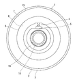
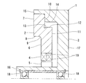
- Sectional drawing which shows the magnetic type load sensor of 1st Embodiment of this invention
- Left side view of the magnetic load sensor shown in FIG. 1 is an enlarged cross-sectional view of the vicinity of the magnetic target of the magnetic load sensor shown in FIG.
- FIG. 2 is an enlarged sectional view showing an example in which the arrangement of the magnetic target and the magnetic sensor shown in FIG. 2 is changed.
- FIG. 2 is an enlarged sectional view showing another example of the magnetic load sensor shown in FIG.
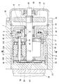
- Sectional drawing which shows the electric brake device using the magnetic type load sensor shown in FIG. Fig. 6 is an enlarged cross-sectional view near the linear actuator.
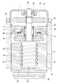
- Sectional view along line VIII-VIII in FIG. Sectional drawing which shows the electric brake device which uses the ball screw mechanism instead of the planetary roller mechanism shown in FIG.
- Sectional drawing which shows the electric brake device which uses the ball ramp mechanism instead of the planetary roller mechanism shown in FIG.
- Sectional view along line XI-XI in FIG. 11A is a view showing the relationship between the ball and the inclined groove shown in FIG. 11, and
- FIG. 11B is a view showing a state in which the rotation disk and the linear motion disk are relatively rotated from the state shown in FIG.
- Figure Sectional drawing which shows the magnetic type load sensor of 2nd Embodiment of this invention Sectional drawing which shows the electric brake device using the magnetic type load sensor shown in FIG.
- Sectional drawing which shows the magnetic type load sensor of a comparative example is a figure which shows the result of having analyzed the radial displacement which arises in each site
- (b) is a figure which shows the result in FIG. The figure which shows the result of having analyzed the radial displacement which arises in each site
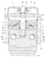
- the magnetic load sensor 1 includes a flange member 2 that generates a deflection when a load is input from the front in the axial direction, a support member 3 that supports the flange member 2 from the rear in the axial direction, a magnetic target 4 that generates magnetic flux, The magnetic sensor 5 detects the magnetic flux generated by the target 4.
- the flange member 2 is a ring-shaped member formed of a metal such as iron.
- a load acting surface 6 On the front surface in the axial direction of the inner diameter side portion of the flange member 2, a load acting surface 6 to which a load is input is formed.
- the load acting surface 6 is a plane perpendicular to the axial direction, and is formed at a position offset axially rearward with respect to the axial front surface 7 of the portion supported by the support member 3 of the flange member 2. Due to this offset, the load acting surface 6 is arranged in a region between the front end and the rear end in the axial direction of the flange member 2 (an intermediate region in the axial direction of the flange member 2).
- the load acting surface 6 and the axial front surface 7 of the portion of the flange member 2 supported by the support member 3 are connected via a step 8.
- a corner R portion 9 having an arcuate cross section that smoothly connects the both is formed. This corner R portion 9 prevents concentration of tensile stress at a position where the load acting surface 6 of the flange member 2 and the step 8 intersect when an axial load is input to the flange member 2 from the front in the axial direction.
- the durability of the flange member 2 is ensured.
- a supported surface 10 supported by the support member 3 is formed on the rear surface in the axial direction of the outer diameter side portion of the flange member 2.
- the supported surface 10 is a plane perpendicular to the axial direction, and is formed at a position that is offset forward in the axial direction with respect to the axial rear surface 11 of the portion to which the load of the flange member 2 is input. Due to this offset, the supported surface 10 is disposed in a region between the axial front end and the rear end of the flange member 2 (an intermediate region in the axial direction of the flange member 2).
- the supported surface 10 and the axial rear surface 11 of the portion where the load of the flange member 2 is input are connected via a step 12.
- a stealing groove 13 having an arc-shaped cross section and extending in the circumferential direction is formed at a position where the supported surface 10 and the step 12 intersect.
- the stealing groove 13 prevents compressive stress from being concentrated at a position where the supported surface 10 of the flange member 2 and the step 12 intersect when an axial load is input to the flange member 2 from the front in the axial direction.
- the durability of the flange member 2 is ensured.
- the support member 3 is made of the same metal as the flange member 2.
- the support member 3 is formed on the outer diameter side of the support portion 14 so as to be fitted to the outer periphery of the flange member 2 and an annular support portion 14 that supports the axial rear surface 11 of the outer diameter side end portion of the flange member 2.
- the fitting cylinder portion 15, the cylindrical portion 16 provided so as to face the inner diameter side of the flange member 2, and the connecting portion 17 that connects the cylindrical portion 16 and the support portion 14 in the axially rearward direction of the flange member 2. And have.
- the support portion 14 of the support member 3 supports the flange member 2 at a position shifted radially outward from the input position of the load to the flange member 2 (that is, the load acting surface 6).
- the flange member 2 is configured such that the inner diameter side portion bends rearward in the axial direction with the position of the supported surface 10 as a fulcrum when a load is input.
- a tightening margin is set between the inner periphery of the fitting tube portion 15 and the outer periphery of the flange member 2.
- the magnetic target 4 is fixed to the inner periphery of the flange member 2.
- the magnetic sensor 5 is fixed to the outer periphery of the cylindrical portion 16 of the support member 3 so as to face the magnetic target 4 in the radial direction.
- a plurality of bearings 18 are mounted on the inner periphery of the cylindrical portion 16 at intervals in the axial direction.
- the magnetic target 4 includes two permanent magnets 19 having a magnetization direction in a direction (radial direction in this case) orthogonal to an axial direction that is a relative displacement direction of the magnetic target 4 and the magnetic sensor 5 due to the deflection of the flange member 2.
- the two permanent magnets 19 are adjacent to each other such that magnetic poles having opposite polarities to the respective permanent magnets 19 (that is, the N pole of one permanent magnet 19 and the S pole of the other permanent magnet 19) are aligned in the axial direction. Are arranged.
- a neodymium magnet is used as the permanent magnet 19
- a powerful magnetic flux can be generated in a space-saving manner. May be.
- a samarium cobalt magnet, a samarium iron nitride magnet, or an alnico magnet is used, a decrease in magnetic flux accompanying a temperature increase of the permanent magnet 19 can be suppressed.
- a praseodymium magnet is used, the mechanical strength of the permanent magnet 19 can be improved.
- the magnetic sensor 5 is disposed in the vicinity of the boundary between adjacent magnetic poles of the two permanent magnets 19 so as to face the magnetic target 4 in the axis orthogonal direction (radial direction in the drawing).
- MR sensor magnetoresistive element
- MI sensor magneto-impedance element
- using a Hall IC is advantageous in terms of cost and has a heat resistance. Since a high Hall IC is commercially available, it is suitable for electric brake applications.
- the magnetic load sensor 1 causes the flange member 2 to move to the outer diameter side end by the axial load.
- the magnetic target 4 and the magnetic sensor 5 are displaced relative to each other in the axial direction, and the output signal of the magnetic sensor 5 is changed according to the relative displacement between the magnetic target 4 and the magnetic sensor 5.
- Change. Therefore, the axial direction applied to the flange member 2 based on the output signal of the magnetic sensor 5 by grasping in advance the relationship between the magnitude of the axial load input to the flange member 2 and the output signal of the magnetic sensor 5. The magnitude of the load can be detected.
- the relative change amount between the magnetic target 4 and the magnetic sensor 5 when an axial load is input to the magnetic load sensor 1 is extremely small.
- a maximum axial load of 30 kN is input to the magnetic load sensor 1, and the magnetic target 4 and the magnetic sensor 5 at this time
- the relative change in the axial direction is about 0.4 mm.
- the magnetic load sensor 1 is arranged at the boundary between the N pole and the S pole. In the vicinity of the magnetic sensor 5, the magnetic flux intersecting in the axial direction exists at a high density.
- the output signal of the magnetic sensor 5 changes sharply with respect to a slight relative displacement in the axial direction between the magnetic target 4 and the magnetic sensor 5. Therefore, although the relative displacement between the magnetic target 4 and the magnetic sensor 5 is extremely small, the magnitude of the axial load acting on the flange member 2 can be detected.
- FIG. 15 shows a magnetic load sensor 80 of a comparative example for the above embodiment.
- the load acting surface 6 of the flange member 2 is not offset with respect to the axial front surface 7 of the flange member 2, and there is no step 8 on the front surface side of the flange member 2.
- the supported surface 10 of the flange member 2 is not offset with respect to the axial rear surface 11 of the flange member 2, and there is no step 12 on the rear surface side of the flange member 2.
- Other configurations are the same as those in the above embodiment.
- FIG. 16A shows the result of analyzing the radial displacement generated in each part of the flange member 2 when an axial load is input from the front in the axial direction to the flange member 2 of the magnetic load sensor 1 of the above embodiment. Shown in (b). This analysis was performed on a 1/36 cut model of the flange member 2.
- the reason why the radial displacement of the load acting surface 6 and the supported surface 10 can be suppressed to be small is considered as follows. That is, when an axial load is inputted to the flange member 2 from the front in the axial direction, the axial front surface 7 of the flange member 2 is displaced radially inward as shown in FIG. Although the direction rear surface 11 is displaced radially outward, the portion between the axial front surface 7 and the axial rear surface 11 of the flange member 2 is hardly displaced in the radial direction. Since the load acting surface 6 and the supported surface 10 are disposed between the axial front surface 7 and the axial rear surface 11 of the flange member 2, the radial displacement of the load acting surface 6 and the supported surface 10 is achieved. Is considered to be small.
- the load acting surface 6 of the flange member 2 is offset rearward in the axial direction with respect to the axial front surface 7 of the flange member 2.
- the displacement in the radial direction of the load acting surface 6 when bending can be suppressed. Therefore, the slip of the load acting surface 6 when a load is input to the flange member 2 is reduced.
- the load increases (that is, when the deflection of the flange member 2 increases) and when the load decreases (that is, the flange member 2) It is possible to prevent a hysteresis error due to slippage of the load acting surface 6 during the time when the deflection is reduced.
- the supported surface 10 of the flange member 2 is offset forward in the axial direction with respect to the axial rear surface 11 of the flange member 2, so the supported surface when the flange member 2 bends.
- the radial displacement of 10 can also be kept small. Therefore, the slip of the supported surface 10 when a load is input to the flange member 2 is reduced, and as a result, it is possible to prevent a hysteresis error due to the slip of the supported surface 10 between the load increase and the load decrease. it can.
- the magnetic load sensor 1 acts on the flange member 2 to bend the flange member 2 but does not act on the magnetic sensor 5. Therefore, even if an impact load or a load oblique to the axial direction is applied, the magnetic sensor 5 is unlikely to fail and high durability can be ensured.
- the flange member 2 and the support member 3 are formed of a material having the same linear expansion coefficient, the flange member 2 and the support member 3 have the same ratio when the temperature rises. Thermal expansion. For this reason, relative displacement between the magnetic target 4 and the magnetic sensor 5 due to temperature change is unlikely to occur, and errors due to temperature change are unlikely to occur.
- the magnetic target 4 is fixed to the flange member 2 and the magnetic sensor 5 is fixed to the support member 3.
- the relationship between the magnetic target 4 and the magnetic sensor 5 may be reversed. That is, as shown in FIG. 4, the magnetic sensor 5 may be fixed to the flange member 2 and the magnetic target 4 may be fixed to the support member 3.
- the load acting surface 6 and the supported surface 10 of the flange member 2 are formed so as to be positioned on the same plane. If it does in this way, it will become possible to reduce effectively the slip of the load action surface 6 when a load is input into the flange member 2, and the slip of the supported surface 10.
- the term “on the same plane” means that the load acting surface 6 and the supported surface 10 of the flange member 2 do not need to be on the same plane in a mathematically strict sense, and the load acting surface 6 and the supported surface are supported. It means that the surface 10 exists in a virtual planar region having a thickness of about 10% of the thickness of the portion to which the load of the flange member 2 is input.
- the load acting surface 6 and the supported surface 10 of the flange member 2 are disposed at an intermediate position that is equidistant from both the axial front surface 7 and the axial rear surface 11 of the flange member 2.
- 6 to 8 show an electric brake device for a vehicle using the magnetic load sensor 1 described above.
- the electric brake device includes a caliper body 25 having a shape in which opposed pieces 22 and 23 facing each other with a bridge 24 interposed therebetween with a brake disc 21 rotating integrally with a wheel, and a facing surface of the opposed piece 23 to the brake disc 21.
- the linear motion actuator 27 is incorporated in the accommodation hole 26 that opens to the left and the left and right friction pads 28 and 29.
- the friction pad 28 is provided between the opposing piece 23 and the brake disk 21 and is supported by a pad pin (not shown) attached to the caliper body 25 so as to be movable in the axial direction of the brake disk 21.
- the other friction pad 29 is attached to the opposing piece 22 on the opposite side.
- the caliper body 25 is supported so as to be slidable in the axial direction of the brake disc 21.
- the linear actuator 27 includes a rotating shaft 30, a plurality of planetary rollers 31 that are in rolling contact with the outer peripheral cylindrical surface of the rotating shaft 30, and an outer ring disposed so as to surround these planetary rollers 31. It has the member 32, the carrier 33 which hold
- the rotary shaft 30 is rotationally driven by the rotation of the electric motor 34 shown in FIG.
- the rotating shaft 30 is inserted into the receiving hole 26 with one end protruding from an opening on the rear side in the axial direction of the receiving hole 26 formed through the opposing piece 23 in the axial direction, and is inserted into the protruding portion from the receiving hole 26.
- the gear 35 is spline-fitted to prevent rotation.
- the gear 35 is covered with a lid 37 fixed with a bolt 36 so as to close the opening on the rear side in the axial direction of the accommodation hole 26.
- the lid 37 incorporates a bearing 38 that rotatably supports the rotary shaft 30.
- the planetary roller 31 is in rolling contact with the outer peripheral cylindrical surface of the rotating shaft 30, and the planetary roller 31 is caused by friction between the planetary roller 31 and the rotating shaft 30 when the rotating shaft 30 rotates. Also comes to rotate.
- a plurality of planetary rollers 31 are provided at regular intervals in the circumferential direction.
- the outer ring member 32 is accommodated in an accommodation hole 26 provided in the facing piece 23 of the caliper body 25, and is supported so as to be slidable in the axial direction on the inner periphery of the accommodation hole 26.
- An engagement recess 40 is formed at the front end in the axial direction of the outer ring member 32 to engage with an engagement protrusion 39 formed on the back surface of the friction pad 28. The engagement protrusion 39 and the engagement recess 40 are engaged with each other. Thus, the outer ring member 32 is prevented from rotating with respect to the caliper body 25.
- a spiral ridge 41 is provided on the inner periphery of the outer ring member 32, and a circumferential groove 42 that engages with the spiral ridge 41 is provided on the outer periphery of the planetary roller 31, so that the planetary roller 31 rotates.
- the spiral protrusion 41 of the outer ring member 32 is guided by the circumferential groove 42 so that the outer ring member 32 moves in the axial direction.
- the circumferential groove 42 having a lead angle of 0 degrees is provided on the outer periphery of the planetary roller 31, but a spiral groove having a lead angle different from that of the spiral protrusion 41 may be provided instead of the circumferential groove 42.
- the carrier 33 includes a carrier pin 33A that rotatably supports the planetary roller 31, an annular carrier plate 33B that maintains a constant circumferential interval at the front end in the axial direction of each carrier pin 33A, and an axial direction of each carrier pin 33A. And an annular carrier body 33C that maintains a constant circumferential interval at the rear end.
- the carrier plate 33B and the carrier main body 33C face the planetary roller 31 in the axial direction, and are connected via a connecting rod 43 disposed between the planetary rollers 31 adjacent in the circumferential direction.
- the carrier body 33 ⁇ / b> C is supported by the rotary shaft 30 via the slide bearing 44 and is rotatable relative to the rotary shaft 30.
- a thrust bearing 45 for interrupting transmission of rotation of the planetary roller 31 to the carrier main body 33C is incorporated.
- Each carrier pin 33A is urged radially inward by a reduced diameter ring spring 46 mounted so as to circumscribe a plurality of carrier pins 33A arranged at intervals in the circumferential direction. Due to the urging force of the reduced diameter ring spring 46, the outer periphery of the planetary roller 31 is pressed against the outer periphery of the rotating shaft 30, and slippage between the rotating shaft 30 and the planetary roller 31 is prevented. In order to apply the urging force of the reduced diameter ring spring 46 over the entire axial length of the planetary roller 31, reduced diameter ring springs 46 are provided at both ends of the carrier pin 33A.
- the magnetic load sensor 1 is fitted in the accommodation hole 26 in the direction in which the support member 3 is positioned behind the flange member 2 in the axial direction.
- a spacer 47 that revolves integrally with the carrier 33 and a thrust bearing 48 that transmits an axial load between the spacer 47 and the magnetic load sensor 1 are incorporated between the carrier 33 and the magnetic load sensor 1.
- the thrust bearing 48 is provided so as to contact the load acting surface 6 of the flange member 2, and an axial load is input from the spacer 47 to the load acting surface 6 of the flange member 2 through the thrust bearing 48. It is like that.
- a rotary shaft 30 is rotatably supported by a bearing 18 incorporated in the cylindrical portion 16 of the support member 3.
- the magnetic load sensor 1 is restricted from moving rearward in the axial direction by locking the outer peripheral edge of the support member 3 with a retaining ring 49 attached to the inner periphery of the accommodation hole 26.
- the magnetic load sensor 1 supports the carrier body 33 ⁇ / b> C in the axial direction via the spacer 47 and the thrust bearing 48, thereby restricting the movement of the carrier 33 in the rearward direction in the axial direction.
- the carrier 33 is also restricted from moving forward in the axial direction by a retaining ring 50 attached to the front end of the rotating shaft 30 in the axial direction. Therefore, the movement of the carrier 33 in both the axial front and the axial rear is restricted, and the planetary roller 31 held by the carrier 33 is also restricted in the axial movement.
- the rotating shaft 30 rotates, and the planetary roller 31 revolves around the rotating shaft 30 while rotating around the carrier pin 33A.
- the outer ring member 32 and the planetary roller 31 move relative to each other in the axial direction due to the engagement between the spiral ridge 41 and the circumferential groove 42, but the planetary roller 31 is restricted from moving in the axial direction together with the carrier 33.
- the roller 31 does not move in the axial direction, and the outer ring member 32 moves in the axial direction.
- the linear actuator 27 converts the rotation of the rotary shaft 30 driven by the electric motor 34 into the axial movement of the outer ring member 32, and applies an axial load to the friction pad 28 by the outer ring member 32.
- the friction pad 28 is pressed against the brake disc 21 to generate a braking force.
- this electric brake device as a linear motion mechanism that converts the rotation of the rotating shaft 30 into the axial movement of the outer ring member 32, a plurality of planetary rollers 31 that are in rolling contact with the outer peripheral cylindrical surface of the rotating shaft 30 and the planetary rollers 31 are provided.
- a carrier 33 that is capable of rotating and revolving and that is restricted from moving in the axial direction, an outer ring member 32 that is disposed so as to surround a plurality of planetary rollers 31, and a spiral ridge provided on the inner periphery of the outer ring member 32 41 and a planetary roller 31 mechanism comprising a spiral groove or a circumferential groove 42 provided on the outer periphery of each planetary roller 31 so as to engage with the spiral ridge 41, but a linear motion of another configuration
- the magnetic load sensor 1 can also be incorporated into an electric brake device that employs a mechanism.
- FIG. 9 shows an example of an electric brake device that employs a ball screw mechanism as a linear motion mechanism.
- a ball screw mechanism as a linear motion mechanism.
- the linear actuator 27 is formed on the outer periphery of the rotating shaft 30, a screw shaft 51 provided integrally with the rotating shaft 30, a nut 52 provided so as to surround the screw shaft 51, and the screw shaft 51.
- a plurality of balls 55 incorporated between the formed screw groove 53 and the screw groove 54 formed on the inner periphery of the nut 52, and a return tube (not shown) for returning the balls 55 from the end point of the screw groove 54 of the nut 52 to the starting point.
- the magnetic load sensor 1 is disposed behind the nut 52 in the axial direction.
- the nut 52 is accommodated in the accommodation hole 26 provided in the facing piece 23 so as to be slidable in the axial direction while being prevented from rotating with respect to the caliper body 25.
- a spacer 47 that rotates integrally with the screw shaft 51 is provided at the rear end in the axial direction of the screw shaft 51, and the spacer 47 is supported by the magnetic load sensor 1 via a thrust bearing 48.
- the magnetic load sensor 1 supports the nut 52 in the axial direction via the spacer 47, the thrust bearing 48, and the screw shaft 51, thereby restricting the movement of the nut 52 in the axial rearward direction. .
- This electric brake device rotates the rotating shaft 30 to rotate the screw shaft 51 and the nut 52 relative to each other, and moves the nut 52 forward in the axial direction to apply an axial load to the friction pad 28.
- a reaction force acting rearward in the axial direction acts on the screw shaft 51, and the reaction force is received by the magnetic load sensor 1 via the spacer 47 and the thrust bearing 48.
- the flange member 2 of the magnetic load sensor 1 bends rearward in the axial direction, and the magnetic target 4 and the magnetic sensor 5 are relatively displaced.
- the output signal of the magnetic sensor 5 changes according to the magnitude of the axial load applied to the friction pad 28, and the magnitude of the axial load is based on the output signal of the magnetic sensor 5. (Pressing force of the friction pad 28) can be detected.
- FIG. 10 shows an example of an electric brake device that employs a ball ramp mechanism as a linear motion mechanism.
- the electric brake device includes a rotating shaft 30, a rotating disk 60 that is prevented from rotating on the outer periphery of the rotating shaft 30, a linearly-moving disk 61 that is disposed in front of the rotating disk 60 in the axial direction, A plurality of balls 62 sandwiched between the disk 60 and the linear motion disk 61, and the magnetic load sensor 1 disposed behind the linear motion disk 61 in the axial direction.
- the linear motion disk 61 is accommodated in an accommodation hole 26 provided in the facing piece 23 so as to be slidable in the axial direction while being prevented from rotating with respect to the caliper body 25.
- a spacer 47 that rotates integrally with the rotating disk 60 is provided at the axial rear end of the rotating disk 60, and the spacer 47 is supported by the magnetic load sensor 1 via a thrust bearing 48.
- the magnetic load sensor 1 supports the rotation disk 60 in the axial direction via the spacer 47 and the thrust bearing 48 to restrict the movement of the rotation disk 60 in the axial direction rearward.
- an inclined groove 63 whose depth gradually decreases along one circumferential direction is formed on the surface of the rotating disk 60 facing the linearly moving disk 61.
- An inclined groove 64 whose depth gradually decreases along the other direction of the circumferential direction is formed on the surface facing the rotating disk 60.
- the ball 62 is incorporated between the inclined groove 63 of the rotating disk 60 and the inclined groove 64 of the linear motion disk 61.
- the balls 62 roll in the inclined grooves 63 and 64, and the interval between the rotating disk 60 and the linearly moving disk 61 is increased.
- This electric brake device rotates the rotary shaft 30 to rotate the linear motion disc 61 and the rotary disc 60 relative to each other, thereby moving the linear motion disc 61 forward in the axial direction and applying an axial load to the friction pad 28. To do. At this time, a reaction force acting rearward in the axial direction acts on the rotating disk 60, and the reaction force is received by the magnetic load sensor 1 via the spacer 47 and the thrust bearing 48. Then, due to the reaction force, the flange member 2 of the magnetic load sensor 1 bends rearward in the axial direction, and the relative position of the magnetic target 4 and the magnetic sensor 5 changes.
- the output signal of the magnetic sensor 5 changes according to the magnitude of the axial load applied to the friction pad 28, and the magnitude of the axial load is based on the output signal of the magnetic sensor 5. It is possible to detect the pressure (the pressing force of the friction pad 28).
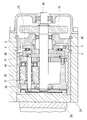
- FIG. 13 shows a magnetic load sensor 70 according to a second embodiment of the present invention. Portions corresponding to the first embodiment are denoted by the same reference numerals and description thereof is omitted.
- a load acting surface 6 on which a load is input is formed on the axially front surface 7 of the outer diameter side portion of the flange member 2.
- the load acting surface 6 is a plane perpendicular to the axial direction, and is formed at a position offset axially rearward with respect to the axial front surface 7 of the portion supported by the support member 3 of the flange member 2.
- a supported surface 10 supported by the support member 3 is formed on the rear surface in the axial direction of the outer diameter side portion of the flange member 2.
- the supported surface 10 is a plane perpendicular to the axial direction, and is formed at a position that is offset forward in the axial direction with respect to the axial rear surface 11 of the portion to which the load of the flange member 2 is input.
- the support member 3 includes an annular support portion 71 that supports the axial rear surface of the inner diameter side portion of the flange member 2, a cylindrical portion 72 that is provided to face the outer diameter side of the flange member 2, and the flange member 2. It has the connection part 73 which connects between the cylindrical part 72 and the support part 71 in the axial direction back.
- the connecting portion 73 has a stepped shape whose inner diameter side is offset rearward in the axial direction, and the outer periphery of the rear end portion in the axial direction of the support portion 71 is fitted to the inner periphery of the stepped portion of the connecting portion 73 with a tightening margin. And integrated.
- the front end portion in the axial direction of the support portion 71 is fitted to the inner periphery of the step 12 on the rear surface side of the flange member 2 with a tightening margin.
- the connecting portion 73 of the supporting member 3 has a contact surface 74 with the supporting portion 71 on the axially front surface of the inner diameter side portion thereof.
- the connecting portion 73 of the support member 3 has an attachment surface 75 on the axially rear surface of the outer diameter side portion.
- the contact surface 74 is formed at a position offset axially rearward with respect to the axial front surface 76 of the connecting portion 73.
- the attachment surface 75 is formed at a position offset forward in the axial direction with respect to the axial rear surface 77 of the connecting portion 73.
- the magnetic target 4 is fixed to the outer periphery of the flange member 2.
- the magnetic sensor 5 is fixed to the inner periphery of the cylindrical portion 72 of the support member 3 so as to face the magnetic target 4 in the radial direction.
- the support portion 71 of the support member 3 supports the flange member 2 at a position shifted inward in the radial direction from the input position of the load to the flange member 2 (that is, the load acting surface 6).
- the flange member 2 is configured such that when the load is input, the outer diameter side portion bends rearward in the axial direction with the position of the supported surface 10 as a fulcrum.
- the magnetic load sensor 70 causes the flange member 2 to move the inner diameter side portion by the axial load.
- the support member 3 bends in the axial direction rearward as a fulcrum, and the support member 3 bends in the axial direction rearward with the outer diameter side end as a fulcrum.
- the output signal of the magnetic sensor 5 changes according to the relative displacement of the magnetic sensor 5.
- the load acting surface 6 of the flange member 2 is offset axially rearward with respect to the axial front surface 7 of the flange member 2 as in the first embodiment.
- the displacement in the radial direction of the load acting surface 6 when bent can be kept small. Therefore, the slip of the load acting surface 6 when a load is input to the flange member 2 is reduced, and as a result, it is possible to prevent a hysteresis error due to the slip of the load acting surface 6 between the load increasing and the load decreasing. Can do.
- the supported surface 10 of the flange member 2 is offset forward in the axial direction with respect to the axial rear surface 11 of the flange member 2 as in the first embodiment.
- the radial displacement of the supported surface 10 when bending is also reduced. Therefore, the slip of the supported surface 10 when a load is input to the flange member 2 is reduced, and as a result, it is possible to prevent a hysteresis error due to the slip of the supported surface 10 between the load increase and the load decrease. it can.
- the contact surface 74 and the attachment surface 75 of the support member 3 are also offset so that the contact surface 74 and the attachment surface of the support member 3 when a load is input to the flange member 2.
- the slippage at 75 is also reduced, and hysteresis errors due to slippage at the contact surface 74 and the mounting surface 75 can be prevented.
- the magnetic load sensor 70 of the second embodiment can also be used by being incorporated in an electric brake device for a vehicle, as in the first embodiment.
Landscapes
- Engineering & Computer Science (AREA)
- General Engineering & Computer Science (AREA)
- Physics & Mathematics (AREA)
- General Physics & Mathematics (AREA)
- Mechanical Engineering (AREA)
- Chemical & Material Sciences (AREA)
- Analytical Chemistry (AREA)
- Combustion & Propulsion (AREA)
- Force Measurement Appropriate To Specific Purposes (AREA)
- Braking Arrangements (AREA)
Priority Applications (3)
| Application Number | Priority Date | Filing Date | Title |
|---|---|---|---|
| EP13817176.4A EP2873957B1 (de) | 2012-07-11 | 2013-07-09 | Magnetischer lastsensor und elektrische bremsvorrichtung |
| CN201380028576.2A CN104428646B (zh) | 2012-07-11 | 2013-07-09 | 磁式负载传感器以及电动制动装置 |
| US14/413,713 US9528889B2 (en) | 2012-07-11 | 2013-07-09 | Magnetic load sensor unit and electric brake system |
Applications Claiming Priority (2)
| Application Number | Priority Date | Filing Date | Title |
|---|---|---|---|
| JP2012-155528 | 2012-07-11 | ||
| JP2012155528A JP5877134B2 (ja) | 2012-07-11 | 2012-07-11 | 磁気式荷重センサおよび電動ブレーキ装置 |
Publications (1)
| Publication Number | Publication Date |
|---|---|
| WO2014010582A1 true WO2014010582A1 (ja) | 2014-01-16 |
Family
ID=49916034
Family Applications (1)
| Application Number | Title | Priority Date | Filing Date |
|---|---|---|---|
| PCT/JP2013/068724 WO2014010582A1 (ja) | 2012-07-11 | 2013-07-09 | 磁気式荷重センサおよび電動ブレーキ装置 |
Country Status (5)
| Country | Link |
|---|---|
| US (1) | US9528889B2 (de) |
| EP (1) | EP2873957B1 (de) |
| JP (1) | JP5877134B2 (de) |
| CN (2) | CN104428646B (de) |
| WO (1) | WO2014010582A1 (de) |
Cited By (1)
| Publication number | Priority date | Publication date | Assignee | Title |
|---|---|---|---|---|
| CN110168334A (zh) * | 2016-12-28 | 2019-08-23 | Ntn株式会社 | 载荷传感器以及电动制动装置 |
Families Citing this family (11)
| Publication number | Priority date | Publication date | Assignee | Title |
|---|---|---|---|---|
| JP5833405B2 (ja) * | 2011-10-11 | 2015-12-16 | Ntn株式会社 | 直動アクチュエータ用の磁気式荷重センサおよび直動アクチュエータ |
| JP5947229B2 (ja) * | 2013-01-10 | 2016-07-06 | Ntn株式会社 | 磁気式荷重センサおよび電動ブレーキ装置 |
| JP6505399B2 (ja) * | 2014-09-02 | 2019-04-24 | Ntn株式会社 | 車両ブレーキ装置用荷重センサ、電動式直動アクチュエータおよび電動ブレーキ装置 |
| JP6133360B2 (ja) | 2015-06-01 | 2017-05-24 | Ntn株式会社 | 電動ブレーキ装置 |
| US10808781B2 (en) | 2016-06-16 | 2020-10-20 | Ntn Corporation | Electric linear motion actuator and electromechanical brake system |
| JP6739262B2 (ja) * | 2016-07-07 | 2020-08-12 | Ntn株式会社 | 電動式直動アクチュエータおよび電動ブレーキ装置 |
| JP6862115B2 (ja) * | 2016-07-13 | 2021-04-21 | Ntn株式会社 | 電動ブレーキ装置 |
| WO2017221939A1 (ja) * | 2016-06-21 | 2017-12-28 | Ntn株式会社 | 電動ブレーキ装置 |
| US11345043B2 (en) * | 2018-07-02 | 2022-05-31 | Flexiv Ltd. | Axial force sensor, robot gripper, and robot having the same |
| US11493407B2 (en) | 2018-09-28 | 2022-11-08 | Ge Avio S.R.L. | Torque measurement system |
| CN116068325B (zh) * | 2023-03-17 | 2023-07-18 | 西安交通大学城市学院 | 一种高低压配电柜负载检测装置 |
Citations (6)
| Publication number | Priority date | Publication date | Assignee | Title |
|---|---|---|---|---|
| JPS57190436U (de) * | 1981-05-28 | 1982-12-02 | ||
| JPS58201041A (ja) * | 1982-05-19 | 1983-11-22 | Mitsubishi Electric Corp | テ−プ張力検出装置 |
| JP2004301835A (ja) * | 2003-03-31 | 2004-10-28 | Robert Bosch Gmbh | 力測定のためのセンサ装置 |
| JP2006514306A (ja) * | 2003-05-07 | 2006-04-27 | ローベルト ボツシユ ゲゼルシヤフト ミツト ベシユレンクテル ハフツング | 力測定素子 |
| JP2010265971A (ja) * | 2009-05-13 | 2010-11-25 | Akebono Brake Ind Co Ltd | 電動式ディスクブレーキ装置 |
| WO2011030839A1 (ja) | 2009-09-10 | 2011-03-17 | 曙ブレーキ工業株式会社 | 電動式ディスクブレーキ |
Family Cites Families (8)
| Publication number | Priority date | Publication date | Assignee | Title |
|---|---|---|---|---|
| JPS57190436A (en) | 1981-05-19 | 1982-11-24 | Fuji Electric Co Ltd | Adjusting method for optical transmitting line |
| US5355714A (en) * | 1992-02-26 | 1994-10-18 | Nippondenso Co., Ltd. | Pressure sensor using a pressure responsive magnetic film to vary inductance of a coil |
| JP3745107B2 (ja) | 1997-08-28 | 2006-02-15 | Jfeアドバンテック株式会社 | ロードセル及びロードセルを備える荷重検出装置 |
| US6507187B1 (en) * | 1999-08-24 | 2003-01-14 | The United States Of America As Represented By The Administrator Of The National Aeronautics And Space Administration | Ultra-sensitive magnetoresistive displacement sensing device |
| WO2004099746A1 (de) | 2003-05-07 | 2004-11-18 | Robert Bosch Gmbh | Kraftmesselement |
| JP5778513B2 (ja) | 2011-07-28 | 2015-09-16 | Ntn株式会社 | 直動アクチュエータ用の磁気式荷重センサおよび直動アクチュエータ |
| JP5735882B2 (ja) * | 2011-08-02 | 2015-06-17 | Ntn株式会社 | 磁気式荷重センサ |
| JP5833405B2 (ja) * | 2011-10-11 | 2015-12-16 | Ntn株式会社 | 直動アクチュエータ用の磁気式荷重センサおよび直動アクチュエータ |
-
2012
- 2012-07-11 JP JP2012155528A patent/JP5877134B2/ja active Active
-
2013
- 2013-07-09 CN CN201380028576.2A patent/CN104428646B/zh active Active
- 2013-07-09 US US14/413,713 patent/US9528889B2/en active Active
- 2013-07-09 WO PCT/JP2013/068724 patent/WO2014010582A1/ja active Application Filing
- 2013-07-09 EP EP13817176.4A patent/EP2873957B1/de active Active
- 2013-07-09 CN CN201710043598.6A patent/CN107063516A/zh active Pending
Patent Citations (6)
| Publication number | Priority date | Publication date | Assignee | Title |
|---|---|---|---|---|
| JPS57190436U (de) * | 1981-05-28 | 1982-12-02 | ||
| JPS58201041A (ja) * | 1982-05-19 | 1983-11-22 | Mitsubishi Electric Corp | テ−プ張力検出装置 |
| JP2004301835A (ja) * | 2003-03-31 | 2004-10-28 | Robert Bosch Gmbh | 力測定のためのセンサ装置 |
| JP2006514306A (ja) * | 2003-05-07 | 2006-04-27 | ローベルト ボツシユ ゲゼルシヤフト ミツト ベシユレンクテル ハフツング | 力測定素子 |
| JP2010265971A (ja) * | 2009-05-13 | 2010-11-25 | Akebono Brake Ind Co Ltd | 電動式ディスクブレーキ装置 |
| WO2011030839A1 (ja) | 2009-09-10 | 2011-03-17 | 曙ブレーキ工業株式会社 | 電動式ディスクブレーキ |
Cited By (2)
| Publication number | Priority date | Publication date | Assignee | Title |
|---|---|---|---|---|
| CN110168334A (zh) * | 2016-12-28 | 2019-08-23 | Ntn株式会社 | 载荷传感器以及电动制动装置 |
| CN110168334B (zh) * | 2016-12-28 | 2022-06-07 | Ntn株式会社 | 载荷传感器以及电动制动装置 |
Also Published As
| Publication number | Publication date |
|---|---|
| JP5877134B2 (ja) | 2016-03-02 |
| EP2873957A4 (de) | 2015-09-02 |
| US20150204736A1 (en) | 2015-07-23 |
| CN104428646A (zh) | 2015-03-18 |
| US9528889B2 (en) | 2016-12-27 |
| CN107063516A (zh) | 2017-08-18 |
| EP2873957A1 (de) | 2015-05-20 |
| CN104428646B (zh) | 2017-02-22 |
| EP2873957B1 (de) | 2018-04-11 |
| JP2014016307A (ja) | 2014-01-30 |
Similar Documents
| Publication | Publication Date | Title |
|---|---|---|
| JP5877134B2 (ja) | 磁気式荷重センサおよび電動ブレーキ装置 | |
| JP5833405B2 (ja) | 直動アクチュエータ用の磁気式荷重センサおよび直動アクチュエータ | |
| JP5778513B2 (ja) | 直動アクチュエータ用の磁気式荷重センサおよび直動アクチュエータ | |
| JP5947229B2 (ja) | 磁気式荷重センサおよび電動ブレーキ装置 | |
| JP5977016B2 (ja) | 電動式直動アクチュエータおよび電動ブレーキ装置 | |
| JP5676382B2 (ja) | 電動ブレーキ装置 | |
| JP5795908B2 (ja) | 電動ブレーキ装置 | |
| WO2016035610A1 (ja) | 荷重センサ、電動式直動アクチュエータおよび電動ブレーキ装置 | |
| JP6055125B2 (ja) | 直動アクチュエータ | |
| JP5865184B2 (ja) | 磁気式荷重センサおよび電動ブレーキ装置 | |
| JP6169676B2 (ja) | 磁気式荷重センサおよび電動ブレーキ装置 | |
| JP5876564B2 (ja) | 電動式直動アクチュエータ |
Legal Events
| Date | Code | Title | Description |
|---|---|---|---|
| 121 | Ep: the epo has been informed by wipo that ep was designated in this application |
Ref document number: 13817176 Country of ref document: EP Kind code of ref document: A1 |
|
| WWE | Wipo information: entry into national phase |
Ref document number: 14413713 Country of ref document: US |
|
| NENP | Non-entry into the national phase |
Ref country code: DE |
|
| WWE | Wipo information: entry into national phase |
Ref document number: 2013817176 Country of ref document: EP |