WO2014010148A1 - スパッタリング装置および磁石ユニット - Google Patents
スパッタリング装置および磁石ユニット Download PDFInfo
- Publication number
- WO2014010148A1 WO2014010148A1 PCT/JP2013/001722 JP2013001722W WO2014010148A1 WO 2014010148 A1 WO2014010148 A1 WO 2014010148A1 JP 2013001722 W JP2013001722 W JP 2013001722W WO 2014010148 A1 WO2014010148 A1 WO 2014010148A1
- Authority
- WO
- WIPO (PCT)
- Prior art keywords
- magnet
- target
- distance
- unit
- side direction
- Prior art date
- Legal status (The legal status is an assumption and is not a legal conclusion. Google has not performed a legal analysis and makes no representation as to the accuracy of the status listed.)
- Ceased
Links
Images






Classifications
-
- H—ELECTRICITY
- H01—ELECTRIC ELEMENTS
- H01J—ELECTRIC DISCHARGE TUBES OR DISCHARGE LAMPS
- H01J37/00—Discharge tubes with provision for introducing objects or material to be exposed to the discharge, e.g. for the purpose of examination or processing thereof
- H01J37/32—Gas-filled discharge tubes
- H01J37/34—Gas-filled discharge tubes operating with cathodic sputtering
- H01J37/3411—Constructional aspects of the reactor
- H01J37/345—Magnet arrangements in particular for cathodic sputtering apparatus
-
- C—CHEMISTRY; METALLURGY
- C23—COATING METALLIC MATERIAL; COATING MATERIAL WITH METALLIC MATERIAL; CHEMICAL SURFACE TREATMENT; DIFFUSION TREATMENT OF METALLIC MATERIAL; COATING BY VACUUM EVAPORATION, BY SPUTTERING, BY ION IMPLANTATION OR BY CHEMICAL VAPOUR DEPOSITION, IN GENERAL; INHIBITING CORROSION OF METALLIC MATERIAL OR INCRUSTATION IN GENERAL
- C23C—COATING METALLIC MATERIAL; COATING MATERIAL WITH METALLIC MATERIAL; SURFACE TREATMENT OF METALLIC MATERIAL BY DIFFUSION INTO THE SURFACE, BY CHEMICAL CONVERSION OR SUBSTITUTION; COATING BY VACUUM EVAPORATION, BY SPUTTERING, BY ION IMPLANTATION OR BY CHEMICAL VAPOUR DEPOSITION, IN GENERAL
- C23C14/00—Coating by vacuum evaporation, by sputtering or by ion implantation of the coating forming material
- C23C14/22—Coating by vacuum evaporation, by sputtering or by ion implantation of the coating forming material characterised by the process of coating
- C23C14/34—Sputtering
- C23C14/35—Sputtering by application of a magnetic field, e.g. magnetron sputtering
-
- H—ELECTRICITY
- H01—ELECTRIC ELEMENTS
- H01J—ELECTRIC DISCHARGE TUBES OR DISCHARGE LAMPS
- H01J37/00—Discharge tubes with provision for introducing objects or material to be exposed to the discharge, e.g. for the purpose of examination or processing thereof
- H01J37/32—Gas-filled discharge tubes
- H01J37/34—Gas-filled discharge tubes operating with cathodic sputtering
- H01J37/3402—Gas-filled discharge tubes operating with cathodic sputtering using supplementary magnetic fields
- H01J37/3405—Magnetron sputtering
-
- H—ELECTRICITY
- H01—ELECTRIC ELEMENTS
- H01F—MAGNETS; INDUCTANCES; TRANSFORMERS; SELECTION OF MATERIALS FOR THEIR MAGNETIC PROPERTIES
- H01F7/00—Magnets
- H01F7/02—Permanent magnets [PM]
- H01F7/0205—Magnetic circuits with PM in general
- H01F7/021—Construction of PM
-
- H—ELECTRICITY
- H01—ELECTRIC ELEMENTS
- H01F—MAGNETS; INDUCTANCES; TRANSFORMERS; SELECTION OF MATERIALS FOR THEIR MAGNETIC PROPERTIES
- H01F7/00—Magnets
- H01F7/02—Permanent magnets [PM]
- H01F7/0205—Magnetic circuits with PM in general
- H01F7/0221—Mounting means for PM, supporting, coating, encapsulating PM
-
- H—ELECTRICITY
- H01—ELECTRIC ELEMENTS
- H01J—ELECTRIC DISCHARGE TUBES OR DISCHARGE LAMPS
- H01J37/00—Discharge tubes with provision for introducing objects or material to be exposed to the discharge, e.g. for the purpose of examination or processing thereof
- H01J37/32—Gas-filled discharge tubes
- H01J37/34—Gas-filled discharge tubes operating with cathodic sputtering
- H01J37/3411—Constructional aspects of the reactor
- H01J37/3435—Target holders (includes backing plates and endblocks)
-
- H—ELECTRICITY
- H01—ELECTRIC ELEMENTS
- H01J—ELECTRIC DISCHARGE TUBES OR DISCHARGE LAMPS
- H01J37/00—Discharge tubes with provision for introducing objects or material to be exposed to the discharge, e.g. for the purpose of examination or processing thereof
- H01J37/32—Gas-filled discharge tubes
- H01J37/34—Gas-filled discharge tubes operating with cathodic sputtering
- H01J37/3411—Constructional aspects of the reactor
- H01J37/345—Magnet arrangements in particular for cathodic sputtering apparatus
- H01J37/3452—Magnet distribution
-
- H—ELECTRICITY
- H01—ELECTRIC ELEMENTS
- H01J—ELECTRIC DISCHARGE TUBES OR DISCHARGE LAMPS
- H01J37/00—Discharge tubes with provision for introducing objects or material to be exposed to the discharge, e.g. for the purpose of examination or processing thereof
- H01J37/32—Gas-filled discharge tubes
- H01J37/34—Gas-filled discharge tubes operating with cathodic sputtering
- H01J37/3411—Constructional aspects of the reactor
- H01J37/3461—Means for shaping the magnetic field, e.g. magnetic shunts
-
- H—ELECTRICITY
- H01—ELECTRIC ELEMENTS
- H01J—ELECTRIC DISCHARGE TUBES OR DISCHARGE LAMPS
- H01J2237/00—Discharge tubes exposing object to beam, e.g. for analysis treatment, etching, imaging
- H01J2237/32—Processing objects by plasma generation
- H01J2237/33—Processing objects by plasma generation characterised by the type of processing
- H01J2237/332—Coating
Definitions
- the present invention relates to a sputtering apparatus and a magnet unit, and more particularly to a sputtering apparatus including a magnetron cathode and a magnet unit provided in the magnetron cathode.
- Patent Document 1 discloses a sputtering apparatus equipped with a flat magnetron cathode that includes a substantially rectangular and flat target holder and swings a substantially rectangular magnet unit.
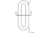
- FIG. 5A and 5B are schematic diagrams showing erosion regions and shapes formed on the target when the substantially rectangular magnet unit is stationary relative to the target.
- FIG. 5A is a plan view showing erosion formed on the target.
- erosion 50 shows an erosion region in the xy plane which is the target surface.
- the area of the erosion 50 has an endless ring shape shown in FIG. 5A.
- FIG. 5B is a cross-sectional view taken along the line VB-VB in FIG. 5A and shows a cross-sectional shape of the erosion 50.
- two valley-shaped erosion 50 are arranged in the direction perpendicular to the long side of the VB-VB line of FIG. 5A, that is, the substantially rectangular magnet unit, and perpendicular to the target surface.
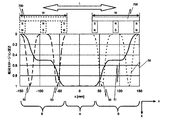
- FIG. 6 shows a simulation result of the erosion shape formed on the target when the substantially rectangular magnet unit is stationary relative to the target and swings relative to the target. It is sectional drawing.
- stationary erosion 50 the erosion formed on the target
- rocking erosion 51 the erosion formed on the target
- 3 shows a virtual static erosion formed on the target.
- the magnet unit 700 swings along the short side direction of the magnet unit 700.
- the stationary erosion 50 moves with respect to the target, and a swinging erosion 51 is formed on the target.
- the stationary erosion 50 and the swing erosion 51 are shown as relative erosion depths normalized by the deepest erosion depth.
- the rocking erosion 51 is roughly divided into a region A in which the stationary erosion 50 completely passes through the target and a region B in which the stationary erosion 50 does not completely pass through the target. . That is, both end portions of the target in the short side direction of the magnet unit shown in the region B of FIG. 6 are left without being effectively utilized.
- the inventor of the present application devised a method for making the width of the magnet thinner than in the past in order to effectively utilize both ends of the target where the erosion is not sufficiently formed and remains engraved, and to further improve the target utilization rate. did. How the target utilization rate is improved by this method will be described with reference to FIG.
- the rocking erosion 51 shown in FIG. 6 is a simulation result of erosion formed when the magnet unit 700 having a short side width W of 120 mm is rocked in a section L having a length of 180 mm.
- the region A having the deepest erosion depth can be expanded and the target utilization rate can be improved. In this way, it is theoretically possible to increase the target utilization rate by narrowing the width W of the magnet unit to expand the region A where the deepest erosion depth is obtained.
- the width W of the magnet unit is narrowed based on this theory, the leakage magnetic flux density on the target surface generated by the magnet unit tends to be low, and the leakage magnetic flux density obtained before changing the width W of the magnet unit is reduced. There is a problem that it is difficult to obtain.
- the present invention has been made in view of the above problems, and an object thereof is to provide a sputtering apparatus and a magnet unit that can obtain a sufficient leakage magnetic flux density on the surface of a target even when the width W of the magnet unit is narrowed. There is to do.
- a target holder having a target placement surface and a surface side of the target holder opposite to the target placement surface are arranged.
- a rectangular magnet unit having a side, wherein the magnet unit is arranged around a first magnet magnetized in a direction perpendicular to the target mounting surface;
- a second magnet magnetized in a direction perpendicular to the target mounting surface and opposite to the magnetization direction of the first magnet, and the first magnet and the second magnet in the short side direction.
- a third magnet magnetized in the short side direction at least in a middle position between the first magnet and the second magnet, Opposing to the second magnet Has the same polarity as the surface of the second magnet on the target holder side, and the surface facing the first magnet has the same polarity as the surface of the first magnet on the target holder side.
- the 2nd aspect of this invention is a rectangular magnet unit which has a long side and a short side, Comprising: The 1st magnet magnetized by the perpendicular direction with respect to the magnet mounting surface and the said magnet mounting surface, A second magnet disposed around the first magnet, perpendicular to the magnet mounting surface and magnetized in the opposite direction different from the magnetization direction of the first magnet, and in the short-side direction A third magnet which is a part between the first magnet and the second magnet and is magnetized in the short-side direction at at least a middle position between the first magnet and the second magnet; The surface of the third magnet facing the second magnet has the same polarity as the surface of the second magnet opposite to the surface on which the magnet is placed, and is opposed to the first magnet. The surface of the first magnet has the same polarity as that of the surface of the first magnet opposite to the magnet mounting surface.
- the leakage magnetic flux density on the target surface can be increased as compared with the conventional case. Therefore, it is possible to provide a sputtering apparatus and a magnetron unit that improve the target utilization by narrowing the width of the magnet unit.
- FIG. 3 is a sectional view taken along line III-III in FIG. 2. It is a top view explaining the magnet unit provided with the yoke of the plate-shaped magnetic material as a conventional 1st magnet, a 2nd magnet, and a magnet mounting part. It is a schematic plan view of ring-shaped erosion formed by a substantially rectangular magnet unit.
- FIG. 5B is a cross-sectional view taken along line VB-VB in FIG. 5A.
- FIG. 1 It is sectional drawing explaining the magnet unit provided with the yoke of the plate-shaped magnetic material as a conventional 1st magnet, a 2nd magnet, and a magnet mounting part. It is sectional drawing explaining the magnet unit provided with the yoke of the plate-shaped magnetic material as a conventional 1st magnet, a 2nd magnet, and a magnet mounting part. It is a figure which shows the magnetic loop formed by the magnetic loop formed by the magnet unit of conventional structure, and the magnet unit which concerns on one Embodiment of this invention. It is a top view for demonstrating the dimension of the magnet unit which concerns on one Embodiment of this invention.
- FIG. 6 is a diagram for explaining a distance from a magnet placement surface of the first to third magnets to a surface opposite to the magnet placement surface according to an embodiment of the present invention.
- FIG. 6 is a diagram for explaining a distance from a magnet placement surface of the first to third magnets to a surface opposite to the magnet placement surface according to an embodiment of the present invention.
- FIG. 6 is a diagram for explaining a distance from a magnet placement surface of the first to third magnets to a surface opposite to the magnet placement surface according to an embodiment of the present invention.
- FIG. 1 is a schematic cross-sectional view for explaining the configuration of a sputtering apparatus applicable to this embodiment.
- the x direction shown in FIG. 1 is the short side direction of the target 5 and the magnet unit 7, and is the swinging direction of the magnet unit 7.
- the sputtering apparatus has a chamber 3, a magnetron cathode 40, and a substrate holder 2 as main components. Further, the sputtering apparatus includes a power source 13 for applying power necessary for the sputtering film forming process to the target holder 4.
- a target holder 4 to which a target 5 is bonded is attached to the chamber 3 (vacuum container) via an insulator 6.
- the insulator 6 is a member that electrically insulates the chamber 3 and the target holder 4.
- the chamber 3, the target holder 4, and the insulator 6 constitute a processing chamber 14 that can be evacuated.
- the target holder 4 is provided with a target mounting surface (target mounting surface) 4a to which the target 5 is bonded by bonding.
- the target mounting surface 4 a is formed as a smooth surface facing the substrate holder 2.
- the target 5 is a material to be deposited and is bonded to the target mounting surface 4a of the target holder 4 as described above.
- a rectangular magnet unit (magnetic circuit unit) 7 having a long side and a short side for applying a magnetic field necessary for magnetron discharge is disposed on the side of the target holder 4 opposite to the target mounting surface 4a.
- the magnet unit 7 is suspended from a screw shaft 8 via a joint 9, and a motor 10 is connected to the screw shaft 8.
- the screw shaft 8 is rotated (forward / reverse) by the motor 10. That is, the joint 9 and the screw shaft 8 constitute a ball screw mechanism, and the magnet unit 7 swings in the x direction (the short side direction of the magnet unit 7) as the screw shaft 8 rotates.
- the motor 10 By controlling the rotation of the motor 10, the moving distance, moving speed and moving direction of the magnet unit 7 can be controlled. In this manner, the magnet unit 7 can be moved as shown by the broken line in FIG. 1 by the swing device including the joint 9, the screw shaft 8 and the motor 10.
- a swing device that moves the magnet unit 7 only in the short side direction of the magnet unit 7 is provided.
- the magnet unit 7 is swung in the y direction that is the long side direction of the magnet unit 7. You may provide the rocking device to move.
- a substrate holder 2 that can hold the substrate 1 so as to face the target 5 is provided inside the chamber 3.
- An exhaust device such as an exhaust pump is connected to the exhaust port 11 of the chamber 3 through a conductance valve (not shown).
- a gas introduction mechanism 12 having a flow rate controller (MFC) and the like is connected to the chamber 3 as process gas introduction means.
- Process gas is supplied from the gas introduction mechanism 12 at a predetermined flow rate.
- a single gas or a mixed gas containing a rare gas such as argon (Ar) or nitrogen (N 2 ) can be used.
- the magnet unit 7 is disposed on the back side of the target holder 4, but a partition plate is provided at a position between the target holder 4 and the magnet unit 7, and the partition plate is a vacuum partition. May be.
- the magnet unit 7 shall say the structure provided with the 1st magnet 71, the 2nd magnet 72, and the 3rd magnet (73a, 73b) at least.
- the magnetron cathode 40 refers to a configuration including at least the magnet unit 7 and the target holder 4.
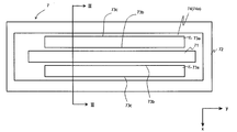
- FIG. 2 is a plan view illustrating details of the magnet unit 7 according to the present embodiment.
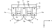
- FIG. 3 is a cross-sectional view illustrating details of the magnet unit 7 according to the present embodiment, and is a cross-sectional view taken along the line III-III in FIG.
- the magnet unit 7 includes a first magnet 71, a second magnet 72, a third magnet 73a, and a magnet placement surface 74a for supporting the first magnet 71, the second magnet 72, and the third magnet 73a. And a magnet mounting portion 74.
- at least the first magnet 71 and the second magnet 72 are placed on the magnet placement surface 74a.
- the long side and the short side of the magnet unit 7 are determined by the first magnet 71 and the second magnet 72.
- a rod-shaped first magnet 71 that is a permanent magnet and a second magnet 72 that is a permanent magnet surrounding the first magnet 71 are mounted apart from each other.
- the first magnet 71 and the second magnet 72 are magnetized in the vertical direction (z direction) with respect to the target surface and the target mounting surface 4a, and their polarities are opposite to each other.
- the first magnet 71 is provided such that the N pole faces the magnet placement surface 74a and the S pole faces the target holder 4 side.
- the second magnet 72 is provided such that the south pole faces the magnet placement surface 74a side and the north pole faces the target holder 4 side. That is, the second magnet 72 is magnetized in the opposite direction different from the magnetization direction of the first magnet 71.
- the third magnet 73a which is a rod-like permanent magnet. That is, the long side direction of the third magnet 73 a and the long side direction of the first magnet 71 coincide with each other, and the midpoint of the short side direction of the third magnet 73 a is between the first magnet 71 and the second magnet 72.
- the third magnet 73a is provided so as to coincide with the middle point.
- the third magnet 73 a is formed along the long side direction (y direction) of the magnet unit 7 and the surface 73 b of the third magnet 73 a on the first magnet 71 side and the first magnet 71. And the distance between the second magnet 72 and the surface 73c on the second magnet 72 side of the third magnet 73a are equal to each other. As shown in FIG. 2, the length of the third magnet 73 a in the long side direction is shorter than the length of the first magnet 71 in the long side direction. Therefore, in the region between the first magnet 71 and the second magnet 72, the third magnet 73a is not disposed at the end of the first magnet 71 in the long side direction.
- the third magnet 73 a is magnetized in a direction (x direction) that is horizontal to the target surface and the target mounting surface 4 a and perpendicular to the long side of the magnet unit 7.
- the polarity of the surface of the third magnet 73a adjacent to the first magnet 71 (the surface facing the first magnet 71) 73b is the same as the polarity of the surface of the first magnet 71 facing the target holder 4 side.
- the surface of the third magnet 73a adjacent to the second magnet 72 (the surface facing the second magnet 71) 73b has the same polarity as the surface of the second magnet 72 on the target holder side.
- the magnet mounting portion 74 is preferably a magnetic material. Further, from the viewpoint of fixing the first magnet 71 and the second magnet 72, it is preferable that the magnet mounting portion 74 exists. However, in the case where a necessary and sufficient magnetic field can be generated only by the first magnet 71, the second magnet 72, and the third magnet 73, the magnet mounting portion 74 may be made of a nonmagnetic material. In this case, when the first magnet 71, the second magnet 72, and the third magnet 73 can be fixed to each other, the magnet placement portion 74 may not be provided.
- a support portion 73d is provided between the third magnet 73a and the magnet placement portion 74.
- the support part 73d is aluminum which is a nonmagnetic material. If a preferable magnetic circuit can be designed, the support portion 73d may be a magnetic material, or may be a magnet having the same magnetization direction and the same polarity as the third magnet 73a. Further, the third magnet 73a may be directly placed on the magnet placement portion 74 without providing the support portion 73d.
- this embodiment demonstrated the form which provides the 1st magnet 71 and the 2nd magnet 72 directly on the magnet mounting part 74, not only this form but the magnet mounting part 74, the 1st magnet 71, and A spacer such as a support portion 73 d may be provided between at least one of the second magnets 72.
- the third magnet 73a may be a single annular magnet. That is, in the present embodiment, the third magnet is at least a part between the first magnet 71 and the second magnet 72 in the short side direction of the first magnet 71 and the second magnet 72, It is important that the second magnet 72 is disposed at least at the center position.
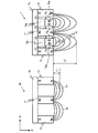
- the magnet unit 90 having a conventional structure has a configuration in which the third magnet 73a and the support portion 73d are removed from the magnet unit 7 according to the present embodiment.
- a magnetic force line (magnetic loop) 91 is formed by the N pole that is the magnetic pole on the target holder side of the first magnet 71 and the S pole that is the magnetic pole on the target holder side of the second magnet 72.
- the distance from the first magnet 71 and the second magnet 72 to the region where the strength of the magnetic field parallel to the target surface (leakage magnetic flux density) at the magnetic field lines 91 is XGauss (X: arbitrary) is L1.
- the magnetic lines of force (magnetic loop) 92 are formed by the first magnet 71 and the second magnet 72 in the same manner as the conventional magnet unit 90. 71 and the second magnet 73 side), a magnetic force line (magnetic loop) 93 is formed by the N pole and the S pole of the third magnet 73a.
- the magnetic field lines 92 emitted from the N pole of the second magnet 72 repel the magnetic lines of force 93 emitted from the N pole of the third magnet 73a.
- the magnetic force line 92 that has come out of the N pole of the second magnet 72 enters the S pole of the first magnet 71 in a form that bypasses the magnetic force line 93 formed by the third magnet 73a.
- the surface 73b (S pole of the third magnet) where the magnetic force line 93 that is directed to the target side from the surface 73c (N pole of the third magnet) facing the second magnet 72 faces the first magnet 71.
- the polarity of the surface 73c is the same polarity as the magnetism of the region of the second magnet 72 facing the surface 73c
- the polarity of the surface 73b is the same polarity as the magnetism of the first magnet 71 facing the surface 73b. Since the third magnet 73a is provided between the first magnet 71 and the second magnet 72 so that the magnetic line of force 93 repelling the magnetic line of force 92 formed by the first magnet 71 and the second magnet, Can be formed inside.
- magnetic field lines 92 relating to the leakage magnetic flux density can be formed far from the magnet unit 7. That is, the distance L2 from the first magnet 71 and the second magnet 72 to the region where the strength of the magnetic field parallel to the target surface in the magnetic field lines 92 related to the leakage magnetic flux density becomes the above-mentioned XGauss is the distance in the conventional magnet unit 90. It can be larger than L1.
- the third magnetic loop (magnetic field line 93) formed by itself is provided so as to repel the magnetic loop (magnetic field line 92) formed by the first magnet 71 and the second magnet 72.
- the magnet 73a acts to form a magnetic field line 92 related to the leakage magnetic flux density at a position away from the magnet unit 7, and a magnetic loop capable of obtaining a predetermined leakage magnetic flux density can be formed farther from the magnet unit 7 than in the past. it can.
- the magnetic force line 92 concerning the leakage magnetic flux density can be formed far from the magnet unit 7, even if the width W in the short side direction of the magnet unit 7 is reduced, it is sufficient on the target surface. Leakage magnetic flux density can be obtained.
- the third magnet 73a is positioned at least in the middle between the first magnet 71 and the second magnet 72, an effect of forming the above-described magnetic loop sufficiently far can be expected.
- the third magnet 73a A distance D1 (D4) between the surface 73c facing the second magnet 72 and the second magnet 72, and a distance D2 between the surface 73b facing the first magnet 71 of the third magnet 73a and the second magnet 71. (D3) can be made the same.
- action to the magnetic force line 93 by the S pole of the 1st magnet 71 can be made the same. Therefore, the magnetic force lines 93 formed on the target side of the third magnet 73a can be made more symmetric, and the magnetic force lines 92 that receive the repulsive action of the magnetic force lines 93 are also formed in a more symmetrical form. Therefore, a region where a predetermined leakage magnetic flux density can be obtained can be formed further away.
- the third magnet 73a is provided such that the midpoint of the third magnet 73a in the short side direction coincides with the midpoint between the first magnet 71 and the second magnet 72.
- the effect of the present invention can be obtained even if the third magnet 73a is provided by deviating from the position where the midpoints coincide.
- the third magnet 73 a characteristic of the present invention is formed between the first magnet 71 and the second magnet 72 in order to form the magnetic field lines 92 relating to the leakage magnetic flux density as far as possible from the magnet unit 7. It is important to provide at least the middle position.
- the magnetic line 93 repelling the magnetic line 92 is formed inside the magnetic line 92 (on the magnet unit 7 side) by the third magnet 73a, and the formation position of the magnetic line 92 can be moved away from the magnet unit 7 by this, the magnet Even if the unit 7 is displaced from the middle position, it is included in one embodiment of the present invention.
- the distances D1, D2, D3, and D4 are preferably 5 mm or less.
- the same polarity of the first magnet 71 and the second magnet 72 and the third magnet 73a can be sufficiently repelled.
- the magnetic field lines 93 coming out from the N pole of the third magnet 73a strongly repel the N poles of the second magnet 72 in the immediate vicinity, and form the magnetic field lines 93 farther on the target side.
- the magnetic force line 92 which came out from the N pole of the 1st magnet 71 is pushed up by the magnetic force line 93 formed farther than the above, and as a result, the magnetic force line 92 is formed farther on the target side.
- the third magnet 73a, the first magnet 71, and the second magnet are sufficiently increased by sufficiently increasing the width of the third magnet 73a (the width of the third magnet 73a in the short side direction (x direction) of the magnet unit 7).
- the magnetic field lines 92 relating to the leakage magnetic flux density can be formed farther on the target side by the magnetic field lines 93 of the third magnet 73a repelled sufficiently by the magnetic field 72.
- the third magnet 73 a may be in contact with at least one of the first magnet 71 and the second magnet 72. Therefore, the distances D1 to D4 are preferably 0 mm or more and 5 mm or less.
- the magnet mounting portion 74 may be a plate-like yoke or a plate-like nonmagnetic material.
- a magnetic loop in which a predetermined leakage magnetic flux density is formed can be formed further from the magnet unit 7.
- the third magnet 73a is a rod-shaped permanent magnet, and the long side direction of the rod-shaped third magnet 73a is made to coincide with the long side direction of the first magnet 71. It is possible to reduce the amount of spatter at the end in the (longitudinal direction) and extend the life of the target. Thus, utilization efficiency can be improved by reducing the long-side end of the target from being deeply cut and extending the life of the target.
- the length a in the long side direction of the rod-shaped first magnet 71 is preferably not less than the length b in the long side direction of the rod-shaped third magnet 73a.
- the distance (interval) ⁇ between the first magnet 71 and the second magnet 72 in the short side direction of the magnet unit 7 is between the first magnet 71 and the second magnet 72 in the long side direction of the magnet unit 7.
- the distance (interval) ⁇ is preferably greater than or equal to.
- region B in FIG. Accordingly, it is possible to reduce the ratio of the amount of abrasion at the location of the area A1 to the amount of abrasion at the location of the area A2. This effect is more remarkable as the distance ⁇ is smaller than the distance ⁇ . Thus, since the said ratio can be made small, the lifetime of a target can be extended and utilization efficiency can be improved.
- the size, shape and material of the target 5 in the present embodiment are a rectangle having a width of 300 mm in the short side direction (x direction) and a length of 1700 mm in the long side direction (y direction), and the thickness (z direction) Is 15 mm aluminum (A1050). Moreover, the thickness (z direction) of the target holder 4 is 20 mm.
- the size of the magnet unit 7 is a rectangle having a short side direction (x direction) length W of 90 mm and a long side direction (y direction) length of 1700 mm.
- the first magnet 71, the second magnet 72, and the third magnet 73a are neodymium magnets having a residual magnetic flux density of 1.39 T and a holding force of 12.8 kOe.
- the magnet mounting part 74 is SUS430.
- the distance from the target holder 4 side surface of the magnet unit 7 to the sputtering surface of the target 5 is 39 mm.
- Symbol g in FIG. 3 indicates the magnetic field lines of the magnetic field generated by the magnet unit 7, and the location of the target 5 indicated by the symbol p corresponding to the apex of the mountain-shaped magnetic field lines (location parallel to the target surface in the magnetic force lines g). Is most easily sputtered.
- the leakage magnetic flux density in the short side direction (x direction) of the magnet unit 7 at the location p was about 510 Gauss.
- FIG. 7 is a diagram showing simulation results of the static erosion 50 and the swing erosion 51 in this embodiment.
- the target utilization rate in the simulation was 69%.
- the target utilization rate obtained by measuring the rocking erosion 51 obtained by actually sputtering the target 5 was 65%.
- a three-dimensional measuring machine equipped with a laser displacement meter which is a non-contact measurement was used for the measurement of the rocking erosion 51.
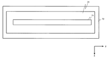
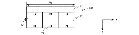
- FIG. 4 is a plan view for explaining the details of a magnet unit 700 which is a conventional technique.
- 8A to 8C are cross-sectional views illustrating details of a magnet unit 700 according to the prior art.
- a rod-shaped first magnet 71 that is a permanent magnet and a second magnet 72 that surrounds the first magnet 71 are placed on a magnet placement portion 74 that is a yoke. Yes.
- the first magnet 71 and the second magnet 72 are magnetized in the direction perpendicular to the target surface and the target placement surface (z direction), and their polarities are opposite to each other.
- the size of the magnet unit 7 shown in FIG. 8A is a rectangle having a width W of 120 mm in the short side direction (x direction) and a length of 1700 mm in the long side direction (y direction). That is, the magnet unit of Comparative Example 1 has the structure described with reference to FIG.
- the first magnet 71 and the second magnet 72 are neodymium magnets having a residual magnetic flux density of 1.39 T and a holding force of 12.8 kOe.
- the magnet mounting part 74 is SUS430.
- the distance from the surface on the target holder side of the magnet unit 700 of Comparative Example 1 to the sputtering surface of the target is 39 mm, which is the same as in this example.
- FIG. 6 shows the simulation results of static erosion 50 and swing erosion 51 in Comparative Example 1.
- the target utilization rate in the simulation was 58%.
- the target usage rate is 69%, and it can be seen that the target usage rate can be improved by this example.
- the size of the magnet unit 7 shown in FIG. 8B is a rectangle having a short side direction (x direction) length W of 90 mm and a long side direction (y direction) length of 1700 mm.
- the sizes of the first magnet 71 and the second magnet 72 are the same as those of the first magnet 71 and the second magnet 72 shown in Comparative Example 1, respectively. That is, in FIG. 8A and FIG. 8B, the distance of the 1st magnet 71 and the 2nd magnet 72 differs with the width W of the magnet unit 7 differing.
- the first magnet 71 and the second magnet 72 are neodymium magnets having a residual magnetic flux density of 1.39 T and a holding force of 12.8 kOe.
- the magnet mounting part 74 is SUS430.
- the distance from the surface on the target holder side of the magnet unit 700 of Comparative Example 2 to the sputtering surface of the target is 39 mm, which is the same as in this example and Comparative Example 1.
- the leakage magnetic flux density in the short side direction (x direction) of the magnet unit 700 in the portion most likely to be sputtered on the target which is described in the present embodiment and indicated by the symbol p in FIG. 3, is about 330 Gauss.
- the 500 Gauss or more obtained in Example 1 could not be obtained.
- this embodiment and comparative example 2 are compared, according to this embodiment, even if the width of the magnet unit in the short side direction is reduced, the leakage magnetic flux density at a predetermined distance from the magnet unit is increased. You can see that
- the size of the magnet unit 7 shown in FIG. 8C is a rectangle with a short side direction (x direction) length W of 90 mm and a long side direction (y direction) length of 1700 mm.
- 8A shown in Comparative Example 1 and FIG. 8B shown in Comparative Example 2 are different in size of the first magnet 71 and the second magnet 72, and the first magnet 71 and the second magnet 72 are not separated from each other. In other words, the leakage flux density is maximized, that is, the maximum leakage magnetic flux density in the prior art is obtained.
- the first magnet 71 and the second magnet 72 are neodymium magnets having a residual magnetic flux density of 1.39 T and a holding force of 12.8 kOe.
- the magnet mounting part 74 is SUS430.
- the distance from the surface on the target holder side of the magnet unit 700 of Comparative Example 3 to the sputtering surface of the target is 39 mm, which is the same as in this example and Comparative Examples 1 and 2.
- the leakage magnetic flux density in the short side direction (x direction) of the magnet unit 700 in the portion most likely to be sputtered on the target which is described in the present embodiment and indicated by the symbol p in FIG. 3, is about 440 Gauss.
- the 500 Gauss or more obtained in Example 1 could not be obtained.
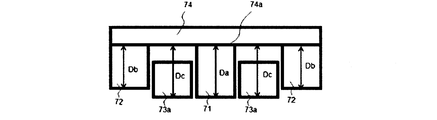
- the distance from the magnet placement surface 74a to the surface opposite to the magnet placement surface 74a (the distance to the target placement surface) of the first magnet 71, the second magnet 72, and the third magnet 73a.
- the case where the length is changed will be described.
- the leakage magnetic field formed on the target surface was examined by simulation. As a result, in the positional relationship shown in FIGS. 11A to 11C, it was possible to increase the strength of the leakage magnetic field on the target surface, that is, to form a magnetic loop further away.
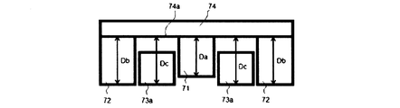
- the first distance from the magnet placement surface 74a to the surface of the first magnet 71 opposite to the magnet placement surface 74a is Da
- the magnet of the second magnet 72 from the magnet placement surface 74a The second distance to the surface opposite to the placement surface 74a is Db
- the third distance from the magnet placement surface 74a to the surface of the third magnet 73a opposite to the magnet placement surface 74a is Dc.
- the first distance Da and the second distance Db are respectively the magnet placement surface 74a.
- FIG. 11A shows a form in which the first distance Da, the second distance Db, and the third distance Dc are all equal.
- FIG. 11B shows a form in which the first distance Da and the third distance Dc are equal, and the second distance Db is smaller than the third distance Dc.
- FIG. 11C shows a form in which the second distance Db and the third distance Dc are equal and the first distance Da is smaller than the third distance Dc. That is, in the present embodiment, it can be said that it is important that the first distance and the second distance have a length equal to or shorter than the third distance, and at least one of the first distance and the second distance is equal to the third distance. .
Landscapes
- Engineering & Computer Science (AREA)
- Physics & Mathematics (AREA)
- Chemical & Material Sciences (AREA)
- Plasma & Fusion (AREA)
- Analytical Chemistry (AREA)
- Electromagnetism (AREA)
- Power Engineering (AREA)
- Materials Engineering (AREA)
- Metallurgy (AREA)
- Organic Chemistry (AREA)
- Mechanical Engineering (AREA)
- Chemical Kinetics & Catalysis (AREA)
- Physical Vapour Deposition (AREA)
Abstract
Description
以下に、本発明の代表的な実施形態を添付図面に基づいて説明する。本発明はこれに限定されるものではなく、本発明の趣旨を逸脱しない範囲において種種の変更が可能である。
なお、磁石ユニット7の長辺および短辺は、第1磁石71、第2磁石72によって決定される。
本実施例におけるターゲット5の大きさ、形状と材質は、幅である短辺方向(x方向)長さ300mm、長辺方向(y方向)長さ1700mmの矩形であり、厚さ(z方向)は15mmのアルミニウム(A1050)である。また、ターゲットホルダ4の厚さ(z方向)は、20mmである。磁石ユニット7の大きさは、幅である短辺方向(x方向)長さWは90mm、長辺方向(y方向)長さ1700mmの矩形である。第1磁石71、第2磁石72、第3磁石73aは、残留磁束密度1.39T、保持力12.8kOeであるネオジム磁石である。また、磁石載置部74はSUS430である。
本発明を実施にあたり、従来技術である図8A~8Cに示す磁石ユニット700により生成される磁場と、ターゲット利用率の検討を行った。
図8Aに示す磁石ユニット7の大きさは、幅である短辺方向(x方向)長さWは120mm、長辺方向(y方向)長さ1700mmの矩形である。すなわち、比較例1の磁石ユニットは図6にて説明した構造である。第1磁石71、第2磁石72は、残留磁束密度1.39T、保持力12.8kOeであるネオジム磁石である。また、磁石載置部74はSUS430である。
図8Bに示す磁石ユニット7の大きさは、幅である短辺方向(x方向)長さWは90mm、長辺方向(y方向)長さ1700mmの矩形である。また、第1磁石71、第2磁石72の大きさはそれぞれ、比較例1に示した第1磁石71、第2磁石72のそれらと同じである。すなわち、図8Aと図8Bにおいては、磁石ユニット7の幅Wが異なることに伴い、第1磁石71と第2磁石72の距離が異なっている。第1磁石71、第2磁石72は、残留磁束密度1.39T、保持力12.8kOeであるネオジム磁石である。また、磁石載置部74はSUS430である。
図8Cに示す磁石ユニット7の大きさは、幅である短辺方向(x方向)長さWは90mm、長辺方向(y方向)長さ1700mmの矩形である。比較例1で示した図8A、比較例2で示した図8Bとは第1磁石71、第2磁石72の大きさが異なり、第1磁石71と第2磁石72とが離間することなくそれらを最大限大きくした、すなわち、従来技術において最大となる漏洩磁束密度が得られる形状である。第1磁石71、第2磁石72は、残留磁束密度1.39T、保持力12.8kOeであるネオジム磁石である。また、磁石載置部74はSUS430である。
本実施形態では、第1磁石71、第2磁石72、第3磁石73aの、磁石載置面74aから該磁石載置面74aと反対側の面までの距離(ターゲット載置面までの距離の長さ)を変更した場合について述べる。
Claims (16)
- ターゲット載置面を有するターゲットホルダと、
前記ターゲットホルダのターゲット載置面と反対の面側に配置され、長辺及び短辺を有する矩形の磁石ユニットと、
を備えたスパッタリング装置であって、
前記磁石ユニットは、
前記ターゲット載置面に対して垂直方向に磁化された第1磁石と、
前記第1磁石の周囲に配置され、前記ターゲット載置面に対して垂直方向であり、かつ前記第1磁石の磁化方向と異なる逆方向に磁化された第2磁石と、
前記短辺方向における前記第1磁石と前記第2磁石との間の一部であって、かつ前記第1磁石と前記第2磁石との間の少なくとも真ん中の位置に前記短辺方向に磁化された第3磁石を有し、
前記第3磁石は、
前記第2磁石と対向する面が、前記第2磁石のターゲットホルダ側の面と同極の極性を有し、
前記第1磁石と対向する面が、前記第1磁石のターゲットホルダ側の面と同極の極性を有することを特徴とするスパッタリング装置。 - 前記磁石ユニットは、前記ターゲットホルダと反対側に前記第1磁石および第2磁石を載置する磁石載置面をさらに有し、
前記磁石載置面から前記第1磁石の該磁石載置面と反対側の面までの第1距離、および前記磁石載置面から前記第2磁石の該磁石載置面と反対側の面までの第2距離は、前記磁石載置面から前記第3磁石の該磁石載置面と反対側の面までの第3距離以下の長さであり、前記第1距離および前記第2距離の少なくとも一方は前記第3距離と等しいことを特徴とする請求項1に記載のスパッタリング装置。 - 前記第2磁石と対向する面と前記第2磁石との間の距離、および前記第1磁石と対向する面と前記第1磁石との間の距離は、5mm以下であることを特徴とする請求項1に記載のスパッタリング装置。
- 前記第1磁石と前記第2磁石との間であって、前記長辺方向の端部には前記第3磁石が配置されていないことを特徴とする請求項1に記載のスパッタリング装置。
- 前記第3磁石の前記長辺方向の長さが、前記第1磁石の前記長辺方向の長さよりも短いことを特徴とする請求項4に記載のスパッタリング装置。
- 前記長辺方向における前記第1磁石と前記第2磁石との間隔が、前記短辺方向における前記第1磁石と前記第2磁石との間隔よりも短いことを特徴とする請求項1に記載のスパッタリング装置。
- 前記磁石ユニットは前記ターゲットホルダと反対側に、前記第1磁石と前記第2磁石を載置する板状のヨークをさらに有することを特徴とする請求項1に記載のスパッタリング装置。
- 前記磁石ユニットは前記ターゲットホルダと反対側に、前記第1磁石と前記第2磁石を載置する板状の非磁性材料を有することを特徴とする請求項1に記載のスパッタリング装置。
- 長辺及び短辺を有する矩形の磁石ユニットであって、
磁石載置面と、
前記磁石載置面に対して垂直方向に磁化された第1磁石と、
前記第1磁石の周囲に配置され、前記磁石載置面に対して垂直方向であり、かつ前記第1磁石の磁化方向と異なる逆方向に磁化された第2磁石と、
前記短辺方向における前記第1磁石と前記第2磁石との間の一部であって、かつ前記第1磁石と前記第2磁石との間の少なくとも真ん中の位置に前記短辺方向に磁化された第3磁石とを備え、
前記第3磁石は、
前記第2磁石と対向する面が、前記第2磁石の、前記磁石載置面と反対側の面と同極の極性を有し、
前記第1磁石と対向する面が、前記第1磁石の、前記磁石載置面と反対側の面と同極の極性を有することを特徴とする磁石ユニット。 - 前記磁石載置面から前記第1磁石の該磁石載置面と反対側の面までの第1距離、および前記磁石載置面から前記第2磁石の該磁石載置面と反対側の面までの第2距離は、前記磁石載置面から前記第3磁石の該磁石載置面と反対側の面までの第3距離以下の長さであり、前記第1距離および前記第2距離の少なくとも一方は前記第3距離と等しいことを特徴とする請求項9に記載の磁石ユニット。
- 前記第2磁石と対向する面と前記第2磁石との間の距離、および前記第1磁石と対向する面と前記第1磁石との間の距離は、5mm以下であることを特徴とする請求項9に記載の磁石ユニット。
- 前記第1磁石と前記第2磁石との間であって、前記長辺方向の端部には前記第3磁石が配置されていないことを特徴とする請求項9に記載の磁石ユニット。
- 前記第3磁石の前記長辺方向の長さが、前記第1磁石の前記長辺方向の長さよりも短いことを特徴とする請求項12に記載の磁石ユニット。
- 前記長辺方向における前記第1磁石と前記第2磁石との間隔が、前記短辺方向における前記第1磁石と前記第2磁石との間隔よりも短いことを特徴とする請求項9に記載の磁石ユニット。
- 前記第1磁石と前記第2磁石を載置する板状のヨークをさらに備えることを特徴とする請求項9に記載の磁石ユニット。
- 前記第1磁石と前記第2磁石を載置する板状の非磁性材料をさらに備えることを特徴とする請求項9に記載の磁石ユニット。
Priority Applications (4)
| Application Number | Priority Date | Filing Date | Title |
|---|---|---|---|
| JP2014524609A JP5873557B2 (ja) | 2012-07-11 | 2013-03-14 | スパッタリング装置および磁石ユニット |
| CN201380036961.1A CN104487607B (zh) | 2012-07-11 | 2013-03-14 | 溅射设备和磁体单元 |
| KR1020157000297A KR101654660B1 (ko) | 2012-07-11 | 2013-03-14 | 스퍼터링 장치 및 자석 유닛 |
| US14/579,290 US9761423B2 (en) | 2012-07-11 | 2014-12-22 | Sputtering apparatus and magnet unit |
Applications Claiming Priority (2)
| Application Number | Priority Date | Filing Date | Title |
|---|---|---|---|
| JP2012-155522 | 2012-07-11 | ||
| JP2012155522 | 2012-07-11 |
Related Child Applications (1)
| Application Number | Title | Priority Date | Filing Date |
|---|---|---|---|
| US14/579,290 Continuation US9761423B2 (en) | 2012-07-11 | 2014-12-22 | Sputtering apparatus and magnet unit |
Publications (1)
| Publication Number | Publication Date |
|---|---|
| WO2014010148A1 true WO2014010148A1 (ja) | 2014-01-16 |
Family
ID=49915637
Family Applications (1)
| Application Number | Title | Priority Date | Filing Date |
|---|---|---|---|
| PCT/JP2013/001722 Ceased WO2014010148A1 (ja) | 2012-07-11 | 2013-03-14 | スパッタリング装置および磁石ユニット |
Country Status (6)
| Country | Link |
|---|---|
| US (1) | US9761423B2 (ja) |
| JP (1) | JP5873557B2 (ja) |
| KR (1) | KR101654660B1 (ja) |
| CN (1) | CN104487607B (ja) |
| TW (1) | TWI493069B (ja) |
| WO (1) | WO2014010148A1 (ja) |
Cited By (1)
| Publication number | Priority date | Publication date | Assignee | Title |
|---|---|---|---|---|
| WO2020003895A1 (ja) * | 2018-06-26 | 2020-01-02 | 株式会社アルバック | 成膜方法および成膜装置 |
Families Citing this family (8)
| Publication number | Priority date | Publication date | Assignee | Title |
|---|---|---|---|---|
| CN105088162B (zh) * | 2015-09-02 | 2019-03-05 | 京东方科技集团股份有限公司 | 一种磁控板、磁控装置及磁控溅射装置 |
| TWI618809B (zh) * | 2016-08-31 | 2018-03-21 | Linco Technology Co Ltd | 具高靶材利用率之磁性靶材陰極裝置 |
| WO2018175689A1 (en) * | 2017-03-22 | 2018-09-27 | Applied Plasma Equipment | Magnetron sputtering source for insulating target materials |
| US11170982B2 (en) * | 2018-08-10 | 2021-11-09 | Applied Materials, Inc. | Methods and apparatus for producing low angle depositions |
| JP7530730B2 (ja) * | 2020-03-30 | 2024-08-08 | 日東電工株式会社 | マグネトロンプラズマ成膜装置 |
| CN116134577A (zh) * | 2020-07-22 | 2023-05-16 | 佳能安内华股份有限公司 | 离子枪和真空处理设备 |
| CN113151792B (zh) * | 2021-03-26 | 2023-01-03 | 洛阳理工学院 | 磁体部件、磁控溅射阴极及柔性线材镀膜用磁控溅射装置 |
| CN115558898B (zh) * | 2022-09-27 | 2024-09-13 | 信利(惠州)智能显示有限公司 | 一种提高靶材利用率的方法 |
Citations (6)
| Publication number | Priority date | Publication date | Assignee | Title |
|---|---|---|---|---|
| JPH04187766A (ja) * | 1990-11-22 | 1992-07-06 | Tdk Corp | マグネトロン・スパッタリング装置用磁気回路装置 |
| JPH06192833A (ja) * | 1992-12-25 | 1994-07-12 | Anelva Corp | スパッタリング装置 |
| JPH10512326A (ja) * | 1995-01-12 | 1998-11-24 | ザ ビーオーシー グループ インコーポレイテッド | 曲面又は扇状エンド・マグネットを持つ回転式マグネトロン |
| JPH11158625A (ja) * | 1997-11-25 | 1999-06-15 | Sony Corp | マグネトロンスパッタ成膜装置 |
| JP2005139521A (ja) * | 2003-11-07 | 2005-06-02 | Matsushita Electric Ind Co Ltd | マグネトロンスパッタ装置および方法 |
| JP2008156735A (ja) * | 2006-12-26 | 2008-07-10 | Hitachi Metals Ltd | マグネトロンスパッタリング用磁気回路 |
Family Cites Families (14)
| Publication number | Priority date | Publication date | Assignee | Title |
|---|---|---|---|---|
| JPH03183123A (ja) * | 1989-12-12 | 1991-08-09 | Fuji Electric Co Ltd | スパッタリング装置 |
| US5262028A (en) * | 1992-06-01 | 1993-11-16 | Sierra Applied Sciences, Inc. | Planar magnetron sputtering magnet assembly |
| JP3808114B2 (ja) * | 1995-06-02 | 2006-08-09 | キヤノンアネルバ株式会社 | スパッタリング装置 |
| JP3925967B2 (ja) | 1996-09-18 | 2007-06-06 | キヤノンアネルバ株式会社 | スパッタリング装置のマグネトロンカソード電極 |
| JP2000239841A (ja) * | 1999-02-24 | 2000-09-05 | Ulvac Japan Ltd | スパッタリング方法と装置 |
| US20030209431A1 (en) * | 2001-04-10 | 2003-11-13 | Brown Jeffrey T. | Magnetron sputtering source with improved target utilization and deposition rate |
| JP2005008917A (ja) * | 2003-06-17 | 2005-01-13 | Nitto Denko Corp | マグネトロンスパッタ装置用カソード |
| US7513982B2 (en) * | 2004-01-07 | 2009-04-07 | Applied Materials, Inc. | Two dimensional magnetron scanning for flat panel sputtering |
| JP2007092136A (ja) * | 2005-09-29 | 2007-04-12 | Shin Meiwa Ind Co Ltd | マグネトロンスパッタリング用の磁石構造体およびカソード電極ユニット並びにマグネトロンスパッタリング装置 |
| JP2007126722A (ja) * | 2005-11-04 | 2007-05-24 | Shin Meiwa Ind Co Ltd | マグネトロンスパッタリング装置用の磁石構造体およびカソード電極ユニット並びにマグネトロンスパッタリング装置 |
| JP5461264B2 (ja) * | 2010-03-25 | 2014-04-02 | キヤノンアネルバ株式会社 | マグネトロンスパッタリング装置、及び、スパッタリング方法 |
| JP2012112040A (ja) * | 2010-11-05 | 2012-06-14 | Shin-Etsu Chemical Co Ltd | スパッタ装置用磁気回路 |
| CN201924073U (zh) * | 2010-12-30 | 2011-08-10 | 河北东旭投资集团有限公司 | 一种平面矩形磁控溅射靶装置 |
| EP2661514B1 (en) * | 2011-01-06 | 2020-06-17 | Bühler AG | Magnetron assembly and sputtering system comprising the same |
-
2013
- 2013-03-14 WO PCT/JP2013/001722 patent/WO2014010148A1/ja not_active Ceased
- 2013-03-14 CN CN201380036961.1A patent/CN104487607B/zh active Active
- 2013-03-14 JP JP2014524609A patent/JP5873557B2/ja active Active
- 2013-03-14 KR KR1020157000297A patent/KR101654660B1/ko active Active
- 2013-07-09 TW TW102124521A patent/TWI493069B/zh active
-
2014
- 2014-12-22 US US14/579,290 patent/US9761423B2/en active Active
Patent Citations (6)
| Publication number | Priority date | Publication date | Assignee | Title |
|---|---|---|---|---|
| JPH04187766A (ja) * | 1990-11-22 | 1992-07-06 | Tdk Corp | マグネトロン・スパッタリング装置用磁気回路装置 |
| JPH06192833A (ja) * | 1992-12-25 | 1994-07-12 | Anelva Corp | スパッタリング装置 |
| JPH10512326A (ja) * | 1995-01-12 | 1998-11-24 | ザ ビーオーシー グループ インコーポレイテッド | 曲面又は扇状エンド・マグネットを持つ回転式マグネトロン |
| JPH11158625A (ja) * | 1997-11-25 | 1999-06-15 | Sony Corp | マグネトロンスパッタ成膜装置 |
| JP2005139521A (ja) * | 2003-11-07 | 2005-06-02 | Matsushita Electric Ind Co Ltd | マグネトロンスパッタ装置および方法 |
| JP2008156735A (ja) * | 2006-12-26 | 2008-07-10 | Hitachi Metals Ltd | マグネトロンスパッタリング用磁気回路 |
Cited By (2)
| Publication number | Priority date | Publication date | Assignee | Title |
|---|---|---|---|---|
| WO2020003895A1 (ja) * | 2018-06-26 | 2020-01-02 | 株式会社アルバック | 成膜方法および成膜装置 |
| JPWO2020003895A1 (ja) * | 2018-06-26 | 2020-07-02 | 株式会社アルバック | 成膜方法および成膜装置 |
Also Published As
| Publication number | Publication date |
|---|---|
| CN104487607B (zh) | 2017-02-22 |
| JP5873557B2 (ja) | 2016-03-01 |
| JPWO2014010148A1 (ja) | 2016-06-20 |
| CN104487607A (zh) | 2015-04-01 |
| KR101654660B1 (ko) | 2016-09-07 |
| TWI493069B (zh) | 2015-07-21 |
| US20150107992A1 (en) | 2015-04-23 |
| TW201418501A (zh) | 2014-05-16 |
| KR20150022982A (ko) | 2015-03-04 |
| US9761423B2 (en) | 2017-09-12 |
Similar Documents
| Publication | Publication Date | Title |
|---|---|---|
| JP5873557B2 (ja) | スパッタリング装置および磁石ユニット | |
| KR101087525B1 (ko) | 스퍼터원, 스퍼터링 장치 및 스퍼터링 방법 | |
| KR101264991B1 (ko) | 마그네트론 스퍼터링 장치 및 스퍼터링 방법 | |
| CN103562433B (zh) | 跑道形状的磁控溅射用磁场产生装置 | |
| US8778150B2 (en) | Magnetron sputtering cathode, magnetron sputtering apparatus, and method of manufacturing magnetic device | |
| CN104093878B (zh) | 磁控溅射用磁场产生装置 | |
| JP2007126722A (ja) | マグネトロンスパッタリング装置用の磁石構造体およびカソード電極ユニット並びにマグネトロンスパッタリング装置 | |
| JP2010248576A (ja) | マグネトロンスパッタリング装置 | |
| KR101608603B1 (ko) | 스퍼터 장치 | |
| JP2006016634A (ja) | 磁界発生装置及びマグネトロン・スパッタ装置 | |
| JP2021001382A (ja) | マグネトロンスパッタリング装置用のカソードユニット | |
| JP2008297577A (ja) | マグネトロンスパッタリング装置 | |
| JP2005068468A (ja) | マグネトロンスパッタリング用ターゲット及びマグネトロンスパッタリング装置 | |
| JP2002069637A (ja) | マグネトロンスパッタリング装置 | |
| JP2016128597A (ja) | マグネットシート、それを使用する成膜方法及びタッチパネル | |
| JP5781408B2 (ja) | マグネトロンスパッタカソード | |
| JP5124317B2 (ja) | シートプラズマ成膜装置、及びシートプラズマ調整方法 | |
| JPH02163372A (ja) | マグネトロンスパッタ装置 | |
| JP2007204811A (ja) | マグネトロンスパッタリング装置用の磁石構造体およびカソード電極ユニット並びにマグネトロンスパッタリング装置並びに磁石構造体の使用方法 | |
| JPH02163371A (ja) | マグネトロンスパッタ装置 | |
| JP2006161062A (ja) | マグネトロンスパッタリング成膜装置及びその電極構造 | |
| TWI532866B (zh) | 磁控濺鍍機 |
Legal Events
| Date | Code | Title | Description |
|---|---|---|---|
| 121 | Ep: the epo has been informed by wipo that ep was designated in this application |
Ref document number: 13817365 Country of ref document: EP Kind code of ref document: A1 |
|
| ENP | Entry into the national phase |
Ref document number: 2014524609 Country of ref document: JP Kind code of ref document: A |
|
| ENP | Entry into the national phase |
Ref document number: 20157000297 Country of ref document: KR Kind code of ref document: A |
|
| NENP | Non-entry into the national phase |
Ref country code: DE |
|
| 122 | Ep: pct application non-entry in european phase |
Ref document number: 13817365 Country of ref document: EP Kind code of ref document: A1 |