WO2014010053A1 - インクジェットヘッドのメンテナンス装置 - Google Patents
インクジェットヘッドのメンテナンス装置 Download PDFInfo
- Publication number
- WO2014010053A1 WO2014010053A1 PCT/JP2012/067758 JP2012067758W WO2014010053A1 WO 2014010053 A1 WO2014010053 A1 WO 2014010053A1 JP 2012067758 W JP2012067758 W JP 2012067758W WO 2014010053 A1 WO2014010053 A1 WO 2014010053A1
- Authority
- WO
- WIPO (PCT)
- Prior art keywords
- ink
- cap member
- inkjet head
- shutter member
- holes
- Prior art date
- Legal status (The legal status is an assumption and is not a legal conclusion. Google has not performed a legal analysis and makes no representation as to the accuracy of the status listed.)
- Ceased
Links
Images


Classifications
-
- B—PERFORMING OPERATIONS; TRANSPORTING
- B41—PRINTING; LINING MACHINES; TYPEWRITERS; STAMPS
- B41J—TYPEWRITERS; SELECTIVE PRINTING MECHANISMS, i.e. MECHANISMS PRINTING OTHERWISE THAN FROM A FORME; CORRECTION OF TYPOGRAPHICAL ERRORS
- B41J2/00—Typewriters or selective printing mechanisms characterised by the printing or marking process for which they are designed
- B41J2/005—Typewriters or selective printing mechanisms characterised by the printing or marking process for which they are designed characterised by bringing liquid or particles selectively into contact with a printing material
- B41J2/01—Ink jet
- B41J2/135—Nozzles
- B41J2/165—Prevention or detection of nozzle clogging, e.g. cleaning, capping or moistening for nozzles
- B41J2/16505—Caps, spittoons or covers for cleaning or preventing drying out
- B41J2/16508—Caps, spittoons or covers for cleaning or preventing drying out connected with the printer frame
-
- B—PERFORMING OPERATIONS; TRANSPORTING
- B41—PRINTING; LINING MACHINES; TYPEWRITERS; STAMPS
- B41J—TYPEWRITERS; SELECTIVE PRINTING MECHANISMS, i.e. MECHANISMS PRINTING OTHERWISE THAN FROM A FORME; CORRECTION OF TYPOGRAPHICAL ERRORS
- B41J2/00—Typewriters or selective printing mechanisms characterised by the printing or marking process for which they are designed
- B41J2/005—Typewriters or selective printing mechanisms characterised by the printing or marking process for which they are designed characterised by bringing liquid or particles selectively into contact with a printing material
- B41J2/01—Ink jet
- B41J2/135—Nozzles
- B41J2/165—Prevention or detection of nozzle clogging, e.g. cleaning, capping or moistening for nozzles
- B41J2/16517—Cleaning of print head nozzles
- B41J2/1652—Cleaning of print head nozzles by driving a fluid through the nozzles to the outside thereof, e.g. by applying pressure to the inside or vacuum at the outside of the print head
- B41J2/16532—Cleaning of print head nozzles by driving a fluid through the nozzles to the outside thereof, e.g. by applying pressure to the inside or vacuum at the outside of the print head by applying vacuum only
-
- B—PERFORMING OPERATIONS; TRANSPORTING
- B41—PRINTING; LINING MACHINES; TYPEWRITERS; STAMPS
- B41J—TYPEWRITERS; SELECTIVE PRINTING MECHANISMS, i.e. MECHANISMS PRINTING OTHERWISE THAN FROM A FORME; CORRECTION OF TYPOGRAPHICAL ERRORS
- B41J2/00—Typewriters or selective printing mechanisms characterised by the printing or marking process for which they are designed
- B41J2/005—Typewriters or selective printing mechanisms characterised by the printing or marking process for which they are designed characterised by bringing liquid or particles selectively into contact with a printing material
- B41J2/01—Ink jet
- B41J2/135—Nozzles
- B41J2/165—Prevention or detection of nozzle clogging, e.g. cleaning, capping or moistening for nozzles
- B41J2/16585—Prevention or detection of nozzle clogging, e.g. cleaning, capping or moistening for nozzles for paper-width or non-reciprocating print heads
Definitions
- the present invention relates to an inkjet head maintenance device for maintaining (ink filling or purging) each ink discharge hole of the inkjet head of the inkjet printing apparatus.
- Inkjet printers are widely used in all fields, whether for personal use or for business use. For example, in the electronics manufacturing industry, patterns for wiring of electronic components, patterns of insulators, dielectrics, etc., and wiring of circuit boards are used. It is used to draw patterns such as resistors.
- each ink discharge hole is formed by pressurizing ink into the ink jet head at the time of initial filling of ink in the ink jet head or sucking each ink discharge hole (nozzle) of the ink jet head from the lower surface side of the ink jet head.
- Ink is filled with ink, but some ink ejection holes are clogged with bubbles or precipitates in the ink, or the viscosity of the ink is increased inside the inkjet head, resulting in poor ink flow. Due to the variation, the hole diameter is narrow and the ink flow is poor, or the pressure drops at the ink discharge hole located far from the ink inlet of the inkjet head. Ink filling unevenness may occur.
- the ink discharge hole is easy to flow once the ink is filled, the pressure acting on the ink discharge hole that is not filled with ink drops, and there is a problem that it is difficult to fill the ink. . Therefore, it is necessary to pressurize or suck ink until all ink ejection holes are filled with ink, and a large amount of ink is wasted.
- Patent Document 1 Japanese Patent Laid-Open No. 2000-272148.
- the cap member 2 is detachably placed on the lower surface portion of the ink jet head 1, and all of the ink jet head 1 is interposed between the lower surface portion of the ink jet head 1 and the cap member 2.
- a sealed space 4 communicating with the ink discharge holes 3 is formed, and suction holes 5a to 5c are formed at three locations on the cap member 2, and valves 7a to 6c are connected to the pipes 6a to 6c connected to the suction holes 5a to 5c, respectively.
- the suction holes on which the suction force is applied are selected by selectively opening the valves 7a to 7c of the pipes 6a to 6c connected to the suction holes 5a to 5c of the cap member 2, respectively.
- the suction hole for selecting the suction force is selected.
- the suction force always acts on all the ink ejection holes 3 only by the change of the suction force acting on the ink ejection holes 3 from the suction holes.
- the ink discharge hole 3 is easy to flow once it is filled with ink. Therefore, the suction force acting on the ink discharge hole 3 not filled with ink is reduced, and the ink is discharged. There was a problem that it was difficult to fill. Therefore, it is necessary to continue sucking ink until all the ink ejection holes 3 are filled with ink, and a large amount of ink is wasted.
- valves 7a to 7c are provided in the suction holes 5a to 5c of the cap member 2, respectively, if the number of the suction holes 5a to 5c is increased, the number of the valves 7a to 7c is increased, and the configuration of the maintenance device is increased. There were also drawbacks that made the system more complex and larger, and the manufacturing cost was higher.
- the problem to be solved by the present invention is that a necessary suction force can be reliably applied to all the ink ejection holes of the ink jet head, and maintainability (ink filling ability / purgeability) of each ink ejection hole. It is to provide a maintenance device for an ink jet head that can improve the efficiency of the maintenance device, and can also simplify the configuration of the maintenance device, reduce the size, and reduce the cost.
- the present invention provides an inkjet head maintenance apparatus for maintaining (ink filling or purging) each ink ejection hole of an inkjet head having a plurality of ink ejection holes formed in a lower surface portion.
- a cap member that is detachably attached to the lower surface portion of the ink jet head, a plurality of communication holes provided in the cap member and connected to a plurality of ink ejection holes of the inkjet head, and provided movably on the cap member,
- a shutter member that selectively opens a plurality of communication holes of the cap member, and by sequentially switching the positions of the communication holes of the cap member that are opened by moving the shutter member, a suction force or a pressing force is applied. It is configured to sequentially switch the positions of the ink discharge holes of the inkjet head. It is intended.
- the position of the ink discharge hole of the inkjet head that applies the suction force or the applied pressure is sequentially switched by sequentially switching the position of the communication hole that is opened by the movement of the shutter member.
- the necessary pressure can be applied to all the ink ejection holes in order, and the maintainability (ink filling ability and purgeability) of each ink ejection hole can be improved.
- the configuration of the maintenance device can be simplified, compared to a configuration in which a valve is provided for each communication hole, and the size and cost are reduced. Can also be realized.
- a seal member that seals a gap in a connection portion between each ink discharge hole of the inkjet head and each communication hole of the cap member. In this way, it is possible to prevent leakage of pressure that is applied to the ink ejection holes in order by movement of the shutter member, and maintenance (ink filling and purging) can be performed efficiently.
- the present invention further includes suction force generating means for applying a suction force to a communication hole opened by the shutter member among the plurality of communication holes of the cap member, and by moving the shutter member, the suction force generating means You may comprise so that the position of the ink discharge hole which applies a suction force may be switched sequentially.
- the position of the ink discharge holes for applying pressure can be sequentially switched by moving the shutter member in a state where the ink in the ink jet head is pressurized by the ink pressurizing function of the ink jet printing apparatus. good.
- the ink jet head maintenance (ink filling or purging) can be performed using the ink pressurizing function of the ink jet printing apparatus.
- each communication hole of the cap member may be formed so that one or a plurality of ink discharge holes of the ink jet head communicate with each other, and the shutter member has a communication hole of the cap member by sliding movement or rotation operation. What is necessary is just to comprise so that it may open
- the present invention may be configured to include an actuator serving as a drive source for moving the shutter member and a control means for controlling the movement of the shutter member by the actuator.
- an actuator serving as a drive source for moving the shutter member
- a control means for controlling the movement of the shutter member by the actuator.
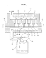
- FIG. 1 is a cross-sectional view illustrating a configuration of a maintenance device for an inkjet head according to a first embodiment of the present invention.
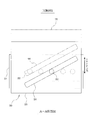
- FIG. 2 is a cross-sectional view taken along line AA in FIG.
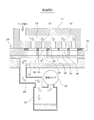
- FIG. 3 is a cross-sectional view illustrating the configuration of the inkjet head maintenance apparatus according to the second embodiment of the present invention.
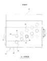
- FIG. 4 is a view corresponding to FIG. 2 and showing the configuration of the shutter member according to the third embodiment of the present invention.
- FIG. 5 is a view corresponding to FIG. 2 and showing the configuration of the shutter member according to the fourth embodiment of the present invention.
- FIG. 6 is a cross-sectional view showing a configuration of a conventional inkjet head maintenance device.
- a first embodiment of the present invention will be described with reference to FIGS.
- a plurality of ink discharge holes 12 are formed in the lower surface portion of the ink jet head 11 of the ink jet printing apparatus, and each ink discharge hole 12 communicates with an ink flow path 13 formed inside the ink jet head 11.
- the ink jet printing apparatus of the first embodiment includes an ink pressurizing function such as a pump that pressurizes and supplies ink from an ink tank (not shown) to the ink flow path 13 in the ink jet head 11. Yes.
- the maintenance device 20 of the inkjet head 11 includes a cap member 21 that is detachably placed on the lower surface of the inkjet head 11.
- the cap member 21 is fixed at a predetermined position of the ink jet printing apparatus, and the ink jet head 11 is moved onto the cap member 21 at the time of maintenance (at the time of ink filling or purging).
- the cap member 21 may be moved, and the cap member 21 may be moved below the inkjet head 11 during maintenance so that the lower surface portion of the inkjet head 11 is covered with the cap member 21. May be.
- the cap member 21 is formed with a plurality of communication holes 22 connected to the plurality of ink ejection holes 12 of the inkjet head 11, and O-rings 23 (seal members) are attached to the opening edge portions of the communication holes 22, respectively.
- O-rings 23 seal members
- the cap member 21 is provided with a shutter member 25 that selectively opens the plurality of communication holes 22 of the cap member 21 so as to be slidable in a horizontal direction (a direction parallel to the lower surface of the inkjet head 11).
- the shutter member 25 is formed with one slit 26 penetrating in the vertical direction.
- the length of the slit 26 is set so that all the communication holes 22 of the cap member 21 are included in the sliding range of the slit 26 by the sliding of the shutter member 25, and the groove width of the slit 26 is the cap member 21.
- the diameter of the communication hole 22 is substantially the same as or slightly larger than that.
- the direction in which the slit 26 extends is not a direction perpendicular to the sliding direction of the shutter member 25, but is inclined at a predetermined angle.
- the sliding hole 22 is opened one by one by the slit 26 by sliding the shutter member 25. Yes.
- a plurality of slits 26 may be formed, or two or more communication holes 22 may be simultaneously opened by one slit 26.
- a waste liquid passage 27 is formed in the cap member 21 along the lower surface of the shutter member 25, and at least a part of the slit 26 of the shutter member 25 communicates with the waste liquid passage 27.
- the waste liquid passage 27 is connected to a waste liquid tank 29 via a pipe 28.
- an exhaust pump 30 suction force generating means for exhausting the inside of the waste liquid tank 29 is provided above the waste liquid tank 29, and the cap member 21 is exhausted by the exhaust pump 30 during maintenance.
- the waste liquid passage 27 is set to a negative pressure, and a suction force is applied to the ink discharge holes 12 of the inkjet head 11 through the slits 26 of the shutter member 25.
- an actuator such as a motor serving as a drive source for sliding the shutter member 25
- the operation of the actuator is controlled by a control device (control means) of the ink jet printing apparatus during maintenance.
- the ink is ejected from the inkjet head 11 that slides the shutter member 25 and sequentially switches the position of the communication hole 22 of the cap member 21 that is opened by the slit 26 of the shutter member 25 to apply a suction force or a pressure force.
- the positions of the holes 12 are sequentially switched.
- the ink in the ink flow path 13 of the inkjet head 11 is added by the ink pressurizing function of the inkjet printing device.
- the exhaust pump 30 is operated to make the waste fluid passage 27 of the cap member 21 negative pressure and the suction force is applied to the slit 26 of the shutter member 25 (or the suction force is applied while pressurizing the ink).
- the shutter member 25 is slid by the actuator in the applied state
- the position of the communication hole 22 of the cap member 21 opened by the slit 26 of the shutter member 25 is sequentially switched to apply a suction force or a pressing force.
- the positions of the ink discharge holes 12 of the inkjet head 11 are sequentially switched.
- the position of the communication hole 22 of the cap member 21 that is opened by the slit 26 of the shutter member 25 is sequentially switched, so that the suction force and the applied pressure are applied. Since the positions of the ink ejection holes 12 of the inkjet head 11 to be switched are sequentially switched, the necessary pressure can be applied to all the ink ejection holes 12 of the inkjet head 11 in order in a reliable manner. 12 maintainability (ink filling property and purge property) can be improved.
- the configuration of the maintenance device 20 is simpler than the configuration in which a valve is provided for each communication hole 22. It is possible to reduce the size and cost.
- the shutter 23 that seals the gap of the connection portion between each ink discharge hole 12 of the inkjet head 11 and each communication hole 22 of the cap member 21 is provided, the shutter The leakage of pressure that is applied to the ink discharge holes 12 in order by sliding of the member 25 can be prevented, and maintenance (ink filling and purging) can be performed efficiently.
- the shutter member 25 is arranged on the lower surface side of the cap member 21 so that the shutter member 25 does not come into contact with the inkjet head 11. Therefore, the shutter member 25 is slid during maintenance.
- the lower surface of the inkjet head 11 is not rubbed by the shutter member 25, and the lower surface of the inkjet head 11 can be prevented from being damaged, and the inkjet head 11 can be made to last longer.
- O-rings 23 are attached to the respective communication holes 22 of the cap member 21 so that the gaps at the connection portions between the respective ink discharge holes 12 of the inkjet head 11 and the respective communication holes 22 of the cap member 21 are formed.
- a single packing 33 in which an opening hole 32 that matches each communication hole 22 is formed in the upper surface portion of the cap member 21. Is installed as a sealing means, and the packing 33 is sandwiched between the cap member 21 and the inkjet head 11, thereby connecting the ink discharge holes 12 of the inkjet head 11 and the communication holes 22 of the cap member 21. The gap is sealed with the packing 33.
- Other configurations are the same as those of the first embodiment.
- the slit 26 is formed in the shutter member 25, but in the third embodiment of the present invention shown in FIG. 4, the shutter member 25 has a plurality of slits corresponding to the plurality of communication holes 22 of the cap member 21.
- the opening hole 35 is formed, and the shutter member 25 is slid to sequentially switch the position of the communication hole 22 of the cap member 21 opened by the opening hole 35 of the shutter member 25.
- each opening hole 35 of the shutter member 25 may be formed large so that two or more communication holes 22 are simultaneously opened by one opening hole 35 of the shutter member 25.
- Other configurations are the same as those in the first or second embodiment.
- the position of the communication hole 22 of the cap member 21 opened by the shutter member 25 is sequentially switched by sliding the shutter member 25.
- the cap member 21 is provided with the shutter member 40 so as to be rotatable about the shaft 41, and the shutter member 40 is formed with a plurality of opening holes 42 corresponding to the plurality of communication holes 22 of the cap member 21, By rotating the shutter member 40 with an actuator such as a motor, the position of the communication hole 22 of the cap member 21 opened by the opening hole 42 of the shutter member 40 is sequentially switched.
- each opening hole 42 of the shutter member 40 may be formed large so that two or more communication holes 22 are simultaneously opened by one opening hole 42 of the shutter member 40.
- Other configurations are the same as those in the first or second embodiment.
- the present invention is not limited to the first to fourth embodiments.
- the arrangement of the ink discharge holes 12 of the inkjet head 11 and the arrangement of the communication holes 22 of the cap member 21 are changed, or the shape of the communication holes 22 is changed.
- the shape of the shutter members 25 and 40 may be changed, and various modifications can be made without departing from the spirit of the invention.
Landscapes
- Coating Apparatus (AREA)
- Ink Jet (AREA)
Description
本発明は、インクジェット印刷装置のインクジェットヘッドの各インク吐出孔をメンテナンス(インク充填やパージ)するインクジェットヘッドのメンテナンス装置に関する発明である。
インクジェット印刷装置は、個人用、業務用を問わず、あらゆる分野で広く使用されており、例えば、エレクトロニクス製造業界においても、電子部品の配線、絶縁体、誘電体等のパターンや、回路基板の配線、抵抗体等のパターンを描画するのに使用されている。いずれのインクジェット印刷装置でも、インクジェットヘッドのインクの初期充填時にインクジェットヘッド内へインクを加圧したり、インクジェットヘッドの下面側から該インクジェットヘッドの各インク吐出孔(ノズル)を吸引して各インク吐出孔にインクを充填するようにしているが、一部のインク吐出孔がインク中の気泡や沈殿物等で詰まったり、インクジェットヘッドの内部でインクが増粘してインクの流れが悪くなったり、製造ばらつきにより孔径が細くてインクの流れが悪いインク吐出孔が出来たり、インクジェットヘッドのインク流入口から遠くに位置するインク吐出孔では圧力が低下したりするため、インクジェットヘッドの各インク吐出孔間でインクの充填むらが生じる可能性がある。
また、インク吐出孔は、インクが一度充填されると、インクが流れやすくなるため、インクが充填されていないインク吐出孔に作用する圧力が低下して、インクを充填しにくいという問題があった。そのため、全てのインク吐出孔にインクが充填されるまでインクを加圧し又は吸引し続ける必要があり、大量のインクを無駄にしていた。
また、インクが一度充填されたインク吐出孔でも、インク中の気泡がインク吐出孔に入り込んで未充填状態に戻ってしまったり、使用していないインク吐出孔内のインクの溶剤成分がインク吐出孔の出口から蒸発してインク吐出孔内でインクが増粘・固化してインク吐出孔が詰まってしまうことがあるため、これを改善するためにも大量のインクを必要としていた。
従来のインクジェットヘッドのメンテナンス装置としては、特許文献1(特開2000-272148号公報)に記載されたものがある。このものは、図5に示すように、インクジェットヘッド1の下面部にキャップ部材2を着脱可能に被せて、インクジェットヘッド1の下面部とキャップ部材2との間に、該インクジェットヘッド1の全てのインク吐出孔3に連通する密閉空間4を形成すると共に、該キャップ部材2の3箇所に吸引孔5a~5cを形成し、各吸引孔5a~5cに接続した配管6a~6cにそれぞれバルブ7a~7cを設け、インクの初期充填時には、3つのバルブ7a~7cを全て開放して3つの吸引孔5a~5cから密閉空間4に吸引力を作用させることで、インクジェットヘッド1の全てのインク吐出孔3を吸引してインクを充填し、定期パージ時(定期クリーニング時)には、両端のバルブ7a,7cのみを開放して両端の吸引孔5a,5cのみから密閉空間4を吸引することで、気泡が溜まりやすいヘッド端部付近のインク吐出孔3から気泡を効率良く除去するようにしている。
上記特許文献1の構成では、キャップ部材2の各吸引孔5a~5cに接続した各配管6a~6cのバルブ7a~7cを選択的に開放することで、吸引力を作用させる吸引孔を選択するようになっているが、3つの吸引孔5a~5cは、いずれも密閉空間4を通してインクジェットヘッド1の全てのインク吐出孔3に連通しているため、吸引力を作用させる吸引孔を選択しても、その吸引孔から各インク吐出孔3に作用する吸引力が変化するだけで、常に全てのインク吐出孔3に吸引力を作用することになる。このため、インクジェットヘッド1の複数のインク吐出孔3のうちの一部のインク吐出孔3が詰まっていたり、インクの流れが悪くなっている場合は、そのインク吐出孔3内のインクの流れを短時間で回復することが困難である。
また、前述したように、インク吐出孔3は、インクが一度充填されると、インクが流れやすくなるため、インクが充填されていないインク吐出孔3に作用する吸引力が低下して、インクを充填しにくいという問題があった。そのため、全てのインク吐出孔3にインクが充填されるまでインクを吸引し続ける必要があり、大量のインクを無駄にしていた。
しかも、キャップ部材2の各吸引孔5a~5cにそれぞれバルブ7a~7cを設けているため、吸引孔5a~5cの数が多くなると、バルブ7a~7cの数も多くなり、メンテナンス装置の構成が複雑化・大型化し、製造コストも高くなる欠点もあった。
そこで、本発明が解決しようとする課題は、インクジェットヘッドの全てのインク吐出孔に確実に必要な吸引力を作用させることができて、各インク吐出孔のメンテナンス性(インク充填性・パージ性)を向上できると共に、メンテナンス装置の構成簡単化、コンパクト化、低コスト化も実現できるインクジェットヘッドのメンテナンス装置を提供することである。
上記課題を解決するために、本発明は、下面部に複数のインク吐出孔が形成されたインクジェットヘッドの各インク吐出孔をメンテナンス(インク充填やパージ)するインクジェットヘッドのメンテナンス装置において、前記インクジェットヘッドの下面部に着脱可能に被せられるキャップ部材と、前記キャップ部材に設けられ、前記インクジェットヘッドの複数のインク吐出孔に接続される複数の連通孔と、前記キャップ部材に移動可能に設けられ、該キャップ部材の複数の連通孔を選択的に開放するシャッタ部材とを備え、前記シャッタ部材を移動させて開放する前記キャップ部材の連通孔の位置を順次切り換えることで、吸引力又は加圧力を作用させる前記インクジェットヘッドのインク吐出孔の位置を順次切り換えるように構成したものである。
この構成によれば、シャッタ部材の移動により開放する連通孔の位置を順次切り換えることで、吸引力又は加圧力を作用させるインクジェットヘッドのインク吐出孔の位置を順次切り換えるようにしているため、インクジェットヘッドの全てのインク吐出孔に順番に確実に必要な圧力を作用させることができて、各インク吐出孔のメンテナンス性(インク充填性やパージ性)を向上できる。しかも、シャッタ部材の移動により開放する連通孔の位置を順次切り換えるようにしているため、連通孔毎にそれぞれバルブを設ける構成と比較して、メンテナンス装置の構成を簡単化でき、コンパクト化や低コスト化も実現できる。 本発明は、インクジェットヘッドの各インク吐出孔とキャップ部材の各連通孔との間の接続部の隙間をシールするシール部材を設けると良い。このようにすれば、シャッタ部材の移動により順番にインク吐出孔に作用させる圧力の漏れを防止でき、メンテナンス(インク充填やパージ)を効率良く行うことができる。
また、本発明は、キャップ部材の複数の連通孔のうちシャッタ部材で開放された連通孔
に吸引力を作用させる吸引力発生手段を備え、シャッタ部材を移動させることで、前記吸引力発生手段の吸引力を作用させるインク吐出孔の位置を順次切り換えるように構成しても良い。
に吸引力を作用させる吸引力発生手段を備え、シャッタ部材を移動させることで、前記吸引力発生手段の吸引力を作用させるインク吐出孔の位置を順次切り換えるように構成しても良い。
或は、インクジェット印刷装置のインク加圧機能によりインクジェットヘッド内のインクを加圧した状態でシャッタ部材を移動させることで、加圧力を作用させるインク吐出孔の位置を順次切り換えるように構成しても良い。この構成では、インクジェット印刷装置のインク加圧機能を利用してインクジェットヘッドのメンテナンス(インク充填やパージ)を行うことができる。
また、キャップ部材の各連通孔は、それぞれインクジェットヘッドのインク吐出孔が1個ずつ又は複数個ずつ連通するように形成すれば良く、シャッタ部材は、スライド移動又は回転動作によりキャップ部材の連通孔を1個ずつ又は複数個ずつ開放するように構成すれば良い。
また、本発明は、シャッタ部材を移動させる駆動源となるアクチュエータと、このアクチュエータによるシャッタ部材の移動を制御する制御手段とを備えた構成とすると良い。これにより、メンテナンス(インク充填やパージ)を自動化することができる。
以下、本発明を実施するための形態を具体化した4つの実施例1~4を説明する。
本発明の実施例1を図1及び図2に基づいて説明する。
インクジェット印刷装置のインクジェットヘッド11の下面部に、複数のインク吐出孔12(ノズル)が形成され、各インク吐出孔12は、インクジェットヘッド11の内部に形成されたインク流路13に連通している。図示はしないが、本実施例1のインクジェット印刷装置は、インクタンク(図示せず)からインクジェットヘッド11内のインク流路13にインクを加圧して供給するポンプ等のインク加圧機能を備えている。
インクジェット印刷装置のインクジェットヘッド11の下面部に、複数のインク吐出孔12(ノズル)が形成され、各インク吐出孔12は、インクジェットヘッド11の内部に形成されたインク流路13に連通している。図示はしないが、本実施例1のインクジェット印刷装置は、インクタンク(図示せず)からインクジェットヘッド11内のインク流路13にインクを加圧して供給するポンプ等のインク加圧機能を備えている。
インクジェットヘッド11のメンテナンス装置20は、インクジェットヘッド11の下面部に着脱可能に被せられるキャップ部材21を備えている。例えば、インクジェット印刷装置の所定位置にキャップ部材21を固定して、メンテナンス時(インク充填時やパージ時)にインクジェットヘッド11をキャップ部材21上へ移動させてインクジェットヘ
ッド11の下面部にキャップ部材21を被せるようにしても良いし、或は、キャップ部材21を移動させる構成とし、メンテナンス時にキャップ部材21をインクジェットヘッド11の下方へ移動させてインクジェットヘッド11の下面部にキャップ部材21を被せるようにしても良い。
ッド11の下面部にキャップ部材21を被せるようにしても良いし、或は、キャップ部材21を移動させる構成とし、メンテナンス時にキャップ部材21をインクジェットヘッド11の下方へ移動させてインクジェットヘッド11の下面部にキャップ部材21を被せるようにしても良い。
キャップ部材21には、インクジェットヘッド11の複数のインク吐出孔12に接続される複数の連通孔22が形成され、各連通孔22の開口縁部には、それぞれOリング23(シール部材)が装着され、インクジェットヘッド11の各インク吐出孔12とキャップ部材21の各連通孔22との間の接続部の隙間がそれぞれOリング23によってシールされている。
キャップ部材21には、キャップ部材21の複数の連通孔22を選択的に開放するシャッタ部材25が水平方向(インクジェットヘッド11の下面と平行な方向)にスライド移動可能に設けられている。図2に示すように、シャッタ部材25には、上下方向に貫通する1本のスリット26が形成されている。このスリット26の長さは、シャッタ部材25のスライドによるスリット26のスライド範囲内にキャップ部材21の全ての連通孔22が含まれるように設定され、また、スリット26の溝幅は、キャップ部材21の連通孔22の直径とほぼ同一又はそれよりも少し大きく形成されている。スリット26の延びる方向は、シャッタ部材25のスライド方向と直角な方向ではなく、所定角度で傾斜し、シャッタ部材25のスライドによりスリット26で連通孔22が1個ずつ開放されるように構成されている。
尚、スリット26は、複数本形成しても良く、また、1つのスリット26で同時に2個以上の連通孔22が開放されるように構成しても良い。
キャップ部材21には、シャッタ部材25の下面に沿って廃液通路27が形成され、該シャッタ部材25のスリット26の少なくとも一部が廃液通路27に連通している。この廃液通路27は、配管28を介して廃液タンク29に接続されている。更に、廃液タンク29の上部には、廃液タンク29内を排気する排気ポンプ30(吸引力発生手段)が設けられ、メンテナンス時に、排気ポンプ30により廃液タンク29内を排気することで、キャップ部材21の廃液通路27を負圧にしてシャッタ部材25のスリット26を通してインクジェットヘッド11のインク吐出孔12に吸引力を作用させるようになっている。
更に、図示はしないが、本実施例1では、シャッタ部材25をスライドさせる駆動源となるモータ等のアクチュエータを備え、メンテナンス時に、インクジェット印刷装置の制御装置(制御手段)により上記アクチュエータの動作を制御することで、シャッタ部材25をスライドさせて、該シャッタ部材25のスリット26で開放するキャップ部材21の連通孔22の位置を順次切り換えて、吸引力や加圧力を作用させるインクジェットヘッド11のインク吐出孔12の位置を順次切り換えるようにしている。
以上のように構成したメンテナンス装置20を用いてインクジェットヘッド11のメンテナンス(インク充填やパージ)を行う場合は、インクジェット印刷装置のインク加圧機能によりインクジェットヘッド11のインク流路13内のインクを加圧した状態、又は、排気ポンプ30を作動させてキャップ部材21の廃液通路27を負圧にしてシャッタ部材25のスリット26に吸引力を作用させた状態(或はインクを加圧しながら吸引力を作用させた状態)で、アクチュエータによりシャッタ部材25をスライドさせることで、該シャッタ部材25のスリット26で開放するキャップ部材21の連通孔22の位置を順次切り換えて、吸引力や加圧力を作用させるインクジェットヘッド11のインク吐出孔12の位置を順次切り換える。
この際、シャッタ部材25のスリット26がキャップ部材21の連通孔22に合致する毎に、シャッタ部材25のスライドを所定時間停止させて、当該連通孔22につながるインク吐出孔12のメンテナンス(インク充填やパージ)を行うという動作を繰り返して、インクジェットヘッド11の全てのインク吐出孔12のメンテナンスを行う。各インク吐出孔12からシャッタ部材25のスリット26を通して廃液通路27内に吸引されたインクの廃液は廃液タンク29内に回収される。
以上説明した本実施例1によれば、シャッタ部材25のスライドにより、該シャッタ部材25のスリット26で開放するキャップ部材21の連通孔22の位置を順次切り換えることで、吸引力や加圧力を作用させるインクジェットヘッド11のインク吐出孔12の位置を順次切り換えるようにしているため、インクジェットヘッド11の全てのインク吐出孔12に順番に確実に必要な圧力を作用させることができて、各インク吐出孔12のメンテナンス性(インク充填性やパージ性)を向上できる。
しかも、シャッタ部材25のスライドにより開放するキャップ部材21の連通孔22の位置を順次切り換えるようにしているため、連通孔22毎にそれぞれバルブを設ける構成と比較して、メンテナンス装置20の構成を簡単化でき、コンパクト化や低コスト化も実現できる。
更に、本実施例1では、インクジェットヘッド11の各インク吐出孔12とキャップ部材21の各連通孔22との間の接続部の隙間をシールするOリング23(シール部材)を設けたので、シャッタ部材25のスライドにより順番にインク吐出孔12に作用させる圧力の漏れを防止でき、メンテナンス(インク充填やパージ)を効率良く行うことができる。
また、本実施例1では、シャッタ部材25をキャップ部材21の下面側に配置して、該シャッタ部材25がインクジェットヘッド11と接触しないように構成されているので、メンテナンス時にシャッタ部材25をスライドさせても、該シャッタ部材25でインクジェットヘッド11の下面が擦られず、インクジェットヘッド11の下面が損傷することを防止でき、インクジェットヘッド11を長持ちさせることができる。
上記実施例1では、キャップ部材21の各連通孔22にそれぞれOリング23を装着してインクジェットヘッド11の各インク吐出孔12とキャップ部材21の各連通孔22との間の接続部の隙間をOリング23でシールするようにしたが、図3に示す本発明の実施例2では、キャップ部材21の上面部に、各連通孔22に合致する開口孔32が形成された1枚のパッキン33をシール手段として装着し、キャップ部材21とインクジェットヘッド11との間に該パッキン33を挟み込むことで、インクジェットヘッド11の各インク吐出孔12とキャップ部材21の各連通孔22との間の接続部の隙間をパッキン33でシールするようにしている。その他の構成は、前記実施例1と同じである。
以上説明した本実施例2でも、前記実施例1と同じ効果を得ることができる。
前記実施例1,2では、シャッタ部材25にスリット26を形成したが、図4に示す本発明の実施例3では、シャッタ部材25に、キャップ部材21の複数の連通孔22に対応して複数の開口孔35を形成し、シャッタ部材25をスライドさせることで、該シャッタ部材25の開口孔35で開放するキャップ部材21の連通孔22の位置を順次切り換えるようにしている。尚、シャッタ部材25の1つの開口孔35で同時に2個以上の連通孔22を開放するようにシャッタ部材25の各開口孔35を大きく形成しても良い。その他の
構成は、前記実施例1又は2と同じである。
構成は、前記実施例1又は2と同じである。
以上説明した本実施例3でも、前記実施例1と同じ効果を得ることができる。
前記実施例1~3では、シャッタ部材25をスライドさせることで、該シャッタ部材25で開放するキャップ部材21の連通孔22の位置を順次切り換えるようにしたが、図5に示す本発明の実施例4では、キャップ部材21にシャッタ部材40を軸41を中心に回転可能に設けると共に、該シャッタ部材40に、キャップ部材21の複数の連通孔22に対応して複数の開口孔42を形成し、シャッタ部材40をモータ等のアクチュエータで回転動作させることで、該シャッタ部材40の開口孔42で開放するキャップ部材21の連通孔22の位置を順次切り換えるようにしている。尚、シャッタ部材40の1つの開口孔42で同時に2個以上の連通孔22を開放するようにシャッタ部材40の各開口孔42を大きく形成しても良い。その他の構成は、前記実施例1又は2と同じである。
以上説明した本実施例4でも、前記実施例1と同じ効果を得ることができる。
尚、本発明は、上記各実施例1~4に限定されず、例えば、インクジェットヘッド11のインク吐出孔12の配列やキャップ部材21の連通孔22の配列を変更したり、連通孔22の形状を変更したり、シャッタ部材25,40の形状を変更しても良い等、要旨を逸脱しない範囲内で種々変更して実施できる。
尚、本発明は、上記各実施例1~4に限定されず、例えば、インクジェットヘッド11のインク吐出孔12の配列やキャップ部材21の連通孔22の配列を変更したり、連通孔22の形状を変更したり、シャッタ部材25,40の形状を変更しても良い等、要旨を逸脱しない範囲内で種々変更して実施できる。
11…インクジェットヘッド、12…インク吐出孔、13…インク流路、20…メンテナンス装置、21…キャップ部材、22…連通孔、23…Oリング(シール部材)、25…シャッタ部材、26…スリット、27…廃液通路、28…配管、29…廃液タンク、30…排気ポンプ(吸引力発生手段)、32…開口孔、33…パッキン(シール手段)、35…開口孔、40…シャッタ部材、41…軸、42…開口孔
Claims (6)
- 下面部に複数のインク吐出孔が形成されたインクジェットヘッドの各インク吐出孔をメンテナンスするインクジェットヘッドのメンテナンス装置において、
前記インクジェットヘッドの下面部に着脱可能に被せられるキャップ部材と、
前記キャップ部材に設けられ、前記インクジェットヘッドの複数のインク吐出孔に接続
される複数の連通孔と、
前記キャップ部材に移動可能に設けられ、該キャップ部材の複数の連通孔を選択的に開放するシャッタ部材とを備え、
前記シャッタ部材を移動させて開放する前記キャップ部材の連通孔の位置を順次切り換えることで、吸引力又は加圧力を作用させるインク吐出孔の位置を順次切り換えるように構成されていることを特徴とするインクジェットヘッドのメンテナンス装置。 - 前記インクジェットヘッドの各インク吐出孔と前記キャップ部材の各連通孔との間の接続部の隙間をシールするシール部材が設けられていることを特徴とする請求項1に記載のインクジェットヘッドのメンテナンス装置。
- 前記キャップ部材の複数の連通孔のうち前記シャッタ部材で開放された連通孔に吸引力を作用させる吸引力発生手段を備え、前記シャッタ部材を移動させることで、前記吸引力発生手段の吸引力を作用させるインク吐出孔の位置を順次切り換えるように構成されていることを特徴とする請求項1又は2に記載のインクジェットヘッドのメンテナンス装置。
- インクジェット印刷装置のインク加圧機能により前記インクジェットヘッド内のインクを加圧した状態で前記シャッタ部材を移動させることで、加圧力を作用させるインク吐出孔の位置を順次切り換えるように構成されていることを特徴とする請求項1乃至3のいずれかに記載のインクジェットヘッドのメンテナンス装置。
- 前記キャップ部材の各連通孔は、それぞれ前記インク吐出孔が1個ずつ又は複数個ずつ連通するように形成され、
前記シャッタ部材は、スライド移動又は回転動作により前記キャップ部材の連通孔を1個ずつ又は複数個ずつ開放するように構成されていることを特徴とする請求項1乃至4のいずれかに記載のインクジェットヘッドのメンテナンス装置。 - 前記シャッタ部材を移動させる駆動源となるアクチュエータと、
前記アクチュエータによる前記シャッタ部材の移動を制御する制御手段と
を備えていることを特徴とする請求項1乃至5のいずれかに記載のインクジェットヘッドのメンテナンス装置。
Priority Applications (2)
| Application Number | Priority Date | Filing Date | Title |
|---|---|---|---|
| PCT/JP2012/067758 WO2014010053A1 (ja) | 2012-07-11 | 2012-07-11 | インクジェットヘッドのメンテナンス装置 |
| JP2014524546A JP6267116B2 (ja) | 2012-07-11 | 2012-07-11 | インクジェットヘッドのメンテナンス装置 |
Applications Claiming Priority (1)
| Application Number | Priority Date | Filing Date | Title |
|---|---|---|---|
| PCT/JP2012/067758 WO2014010053A1 (ja) | 2012-07-11 | 2012-07-11 | インクジェットヘッドのメンテナンス装置 |
Publications (1)
| Publication Number | Publication Date |
|---|---|
| WO2014010053A1 true WO2014010053A1 (ja) | 2014-01-16 |
Family
ID=49915555
Family Applications (1)
| Application Number | Title | Priority Date | Filing Date |
|---|---|---|---|
| PCT/JP2012/067758 Ceased WO2014010053A1 (ja) | 2012-07-11 | 2012-07-11 | インクジェットヘッドのメンテナンス装置 |
Country Status (2)
| Country | Link |
|---|---|
| JP (1) | JP6267116B2 (ja) |
| WO (1) | WO2014010053A1 (ja) |
Cited By (3)
| Publication number | Priority date | Publication date | Assignee | Title |
|---|---|---|---|---|
| WO2020046311A1 (en) * | 2018-08-30 | 2020-03-05 | Hewlett-Packard Development Company, L.P. | Rotatable dispensing nozzles |
| JP2022140243A (ja) * | 2021-03-10 | 2022-09-26 | 株式会社リコー | 吸引キャップの開口を規制する治具、吸引キャップの開口を規制する複数の治具からなるユニット、液体を吐出する装置 |
| EP4617070A1 (en) * | 2024-03-12 | 2025-09-17 | Brady Worldwide, Inc. | Printer maintenance carousel system and method |
Citations (5)
| Publication number | Priority date | Publication date | Assignee | Title |
|---|---|---|---|---|
| JPH1120178A (ja) * | 1997-07-07 | 1999-01-26 | Canon Inc | インクジェット記録ヘッド用回復キャップ |
| JP2003025611A (ja) * | 2001-07-19 | 2003-01-29 | Ricoh Co Ltd | 画像記録装置 |
| JP2008254351A (ja) * | 2007-04-05 | 2008-10-23 | Seiko Epson Corp | 吸引装置、印刷装置及びマイクロアレイの製造装置 |
| JP2008260133A (ja) * | 2007-04-10 | 2008-10-30 | Fuji Xerox Co Ltd | 液滴吐出装置 |
| JP2011245681A (ja) * | 2010-05-25 | 2011-12-08 | Seiko Epson Corp | メンテナンス装置及び流体噴射装置 |
Family Cites Families (1)
| Publication number | Priority date | Publication date | Assignee | Title |
|---|---|---|---|---|
| JP2001334689A (ja) * | 2000-05-26 | 2001-12-04 | Seiko Instruments Inc | インクジェット式記録装置 |
-
2012
- 2012-07-11 JP JP2014524546A patent/JP6267116B2/ja not_active Expired - Fee Related
- 2012-07-11 WO PCT/JP2012/067758 patent/WO2014010053A1/ja not_active Ceased
Patent Citations (5)
| Publication number | Priority date | Publication date | Assignee | Title |
|---|---|---|---|---|
| JPH1120178A (ja) * | 1997-07-07 | 1999-01-26 | Canon Inc | インクジェット記録ヘッド用回復キャップ |
| JP2003025611A (ja) * | 2001-07-19 | 2003-01-29 | Ricoh Co Ltd | 画像記録装置 |
| JP2008254351A (ja) * | 2007-04-05 | 2008-10-23 | Seiko Epson Corp | 吸引装置、印刷装置及びマイクロアレイの製造装置 |
| JP2008260133A (ja) * | 2007-04-10 | 2008-10-30 | Fuji Xerox Co Ltd | 液滴吐出装置 |
| JP2011245681A (ja) * | 2010-05-25 | 2011-12-08 | Seiko Epson Corp | メンテナンス装置及び流体噴射装置 |
Cited By (6)
| Publication number | Priority date | Publication date | Assignee | Title |
|---|---|---|---|---|
| WO2020046311A1 (en) * | 2018-08-30 | 2020-03-05 | Hewlett-Packard Development Company, L.P. | Rotatable dispensing nozzles |
| US11970005B2 (en) | 2018-08-30 | 2024-04-30 | Hewlett-Packard Development Company, L.P. | Rotatable dispensing nozzles |
| JP2022140243A (ja) * | 2021-03-10 | 2022-09-26 | 株式会社リコー | 吸引キャップの開口を規制する治具、吸引キャップの開口を規制する複数の治具からなるユニット、液体を吐出する装置 |
| JP7745826B2 (ja) | 2021-03-10 | 2025-09-30 | 株式会社リコー | 吸引キャップの開口を規制する治具、液体を吐出する装置 |
| EP4617070A1 (en) * | 2024-03-12 | 2025-09-17 | Brady Worldwide, Inc. | Printer maintenance carousel system and method |
| US12589597B2 (en) | 2024-03-12 | 2026-03-31 | Brady Worldwide, Inc. | Printer maintenance carousel system and method |
Also Published As
| Publication number | Publication date |
|---|---|
| JP6267116B2 (ja) | 2018-01-24 |
| JPWO2014010053A1 (ja) | 2016-06-20 |
Similar Documents
| Publication | Publication Date | Title |
|---|---|---|
| JP6256692B2 (ja) | 液体噴射装置及びその制御方法 | |
| US7281785B2 (en) | Fluid handling in droplet deposition systems | |
| CN104943383B (zh) | 液体喷出头及其控制方法、液体喷出装置、流道部件 | |
| CN104441978B (zh) | 液体喷射装置及加减压方法 | |
| JP7005908B2 (ja) | 液体噴射ヘッドユニット及び液体噴射装置 | |
| CN101746145B (zh) | 流体喷射装置 | |
| JP7095243B2 (ja) | 液体吐出装置および液体吐出装置の制御方法 | |
| JP6267116B2 (ja) | インクジェットヘッドのメンテナンス装置 | |
| JP6458928B2 (ja) | 液体吐出ヘッド、液体吐出装置および液体吐出ヘッドの制御方法 | |
| CN102256802A (zh) | 液体喷射头、液体喷射记录装置以及液体喷射头的液体填充方法 | |
| JP6382007B2 (ja) | インクジェットヘッドのメンテナンス方法、液体噴射記録装置、およびメンテナンス装置 | |
| JP2013510021A (ja) | インクジェットプリンタ | |
| WO2016199370A1 (ja) | 液体吐出装置およびその制御方法 | |
| JP2011240624A (ja) | 記録装置 | |
| JP2011121295A (ja) | 流体噴射装置 | |
| JP6191295B2 (ja) | 画像形成装置 | |
| CN102341241A (zh) | 墨水填充方法 | |
| JP5482270B2 (ja) | メンテナンス装置、液体噴射装置、及びメンテナンス方法 | |
| JP6380734B2 (ja) | 液体吐出ヘッドおよび液体吐出装置 | |
| JP2004508973A (ja) | インクジェットプリント装置のためのクリーニングユニット | |
| JP2011245682A (ja) | メンテナンス装置、流体噴射装置及びメンテナンス方法 | |
| JP2008246953A (ja) | インクジェット記録装置 | |
| JP2016068299A (ja) | 液体噴射装置 | |
| KR20070078205A (ko) | 잉크젯 프린팅 시스템의 잉크 공급 장치 | |
| JP2018001663A (ja) | 液体噴射装置 |
Legal Events
| Date | Code | Title | Description |
|---|---|---|---|
| 121 | Ep: the epo has been informed by wipo that ep was designated in this application |
Ref document number: 12881000 Country of ref document: EP Kind code of ref document: A1 |
|
| ENP | Entry into the national phase |
Ref document number: 2014524546 Country of ref document: JP Kind code of ref document: A |
|
| NENP | Non-entry into the national phase |
Ref country code: DE |
|
| 122 | Ep: pct application non-entry in european phase |
Ref document number: 12881000 Country of ref document: EP Kind code of ref document: A1 |