WO2014007381A1 - 情報処理装置、情報処理装置の制御方法、制御プログラム、コンピュータ読み取り可能な記録媒体 - Google Patents
情報処理装置、情報処理装置の制御方法、制御プログラム、コンピュータ読み取り可能な記録媒体 Download PDFInfo
- Publication number
- WO2014007381A1 WO2014007381A1 PCT/JP2013/068550 JP2013068550W WO2014007381A1 WO 2014007381 A1 WO2014007381 A1 WO 2014007381A1 JP 2013068550 W JP2013068550 W JP 2013068550W WO 2014007381 A1 WO2014007381 A1 WO 2014007381A1
- Authority
- WO
- WIPO (PCT)
- Prior art keywords
- virtual
- touch screen
- input device
- screen display
- display
- Prior art date
- Legal status (The legal status is an assumption and is not a legal conclusion. Google has not performed a legal analysis and makes no representation as to the accuracy of the status listed.)
- Ceased
Links
Images








Classifications
-
- G—PHYSICS
- G06—COMPUTING OR CALCULATING; COUNTING
- G06F—ELECTRIC DIGITAL DATA PROCESSING
- G06F3/00—Input arrangements for transferring data to be processed into a form capable of being handled by the computer; Output arrangements for transferring data from processing unit to output unit, e.g. interface arrangements
- G06F3/01—Input arrangements or combined input and output arrangements for interaction between user and computer
- G06F3/048—Interaction techniques based on graphical user interfaces [GUI]
- G06F3/0487—Interaction techniques based on graphical user interfaces [GUI] using specific features provided by the input device, e.g. functions controlled by the rotation of a mouse with dual sensing arrangements, or of the nature of the input device, e.g. tap gestures based on pressure sensed by a digitiser
- G06F3/0488—Interaction techniques based on graphical user interfaces [GUI] using specific features provided by the input device, e.g. functions controlled by the rotation of a mouse with dual sensing arrangements, or of the nature of the input device, e.g. tap gestures based on pressure sensed by a digitiser using a touch-screen or digitiser, e.g. input of commands through traced gestures
- G06F3/04886—Interaction techniques based on graphical user interfaces [GUI] using specific features provided by the input device, e.g. functions controlled by the rotation of a mouse with dual sensing arrangements, or of the nature of the input device, e.g. tap gestures based on pressure sensed by a digitiser using a touch-screen or digitiser, e.g. input of commands through traced gestures by partitioning the display area of the touch-screen or the surface of the digitising tablet into independently controllable areas, e.g. virtual keyboards or menus
-
- G—PHYSICS
- G06—COMPUTING OR CALCULATING; COUNTING
- G06F—ELECTRIC DIGITAL DATA PROCESSING
- G06F3/00—Input arrangements for transferring data to be processed into a form capable of being handled by the computer; Output arrangements for transferring data from processing unit to output unit, e.g. interface arrangements
- G06F3/01—Input arrangements or combined input and output arrangements for interaction between user and computer
- G06F3/048—Interaction techniques based on graphical user interfaces [GUI]
- G06F3/0487—Interaction techniques based on graphical user interfaces [GUI] using specific features provided by the input device, e.g. functions controlled by the rotation of a mouse with dual sensing arrangements, or of the nature of the input device, e.g. tap gestures based on pressure sensed by a digitiser
- G06F3/0488—Interaction techniques based on graphical user interfaces [GUI] using specific features provided by the input device, e.g. functions controlled by the rotation of a mouse with dual sensing arrangements, or of the nature of the input device, e.g. tap gestures based on pressure sensed by a digitiser using a touch-screen or digitiser, e.g. input of commands through traced gestures
-
- G—PHYSICS
- G06—COMPUTING OR CALCULATING; COUNTING
- G06F—ELECTRIC DIGITAL DATA PROCESSING
- G06F3/00—Input arrangements for transferring data to be processed into a form capable of being handled by the computer; Output arrangements for transferring data from processing unit to output unit, e.g. interface arrangements
- G06F3/01—Input arrangements or combined input and output arrangements for interaction between user and computer
- G06F3/048—Interaction techniques based on graphical user interfaces [GUI]
- G06F3/0487—Interaction techniques based on graphical user interfaces [GUI] using specific features provided by the input device, e.g. functions controlled by the rotation of a mouse with dual sensing arrangements, or of the nature of the input device, e.g. tap gestures based on pressure sensed by a digitiser
- G06F3/0488—Interaction techniques based on graphical user interfaces [GUI] using specific features provided by the input device, e.g. functions controlled by the rotation of a mouse with dual sensing arrangements, or of the nature of the input device, e.g. tap gestures based on pressure sensed by a digitiser using a touch-screen or digitiser, e.g. input of commands through traced gestures
- G06F3/04883—Interaction techniques based on graphical user interfaces [GUI] using specific features provided by the input device, e.g. functions controlled by the rotation of a mouse with dual sensing arrangements, or of the nature of the input device, e.g. tap gestures based on pressure sensed by a digitiser using a touch-screen or digitiser, e.g. input of commands through traced gestures for inputting data by handwriting, e.g. gesture or text
-
- G—PHYSICS
- G06—COMPUTING OR CALCULATING; COUNTING
- G06F—ELECTRIC DIGITAL DATA PROCESSING
- G06F2203/00—Indexing scheme relating to G06F3/00 - G06F3/048
- G06F2203/048—Indexing scheme relating to G06F3/048
- G06F2203/04808—Several contacts: gestures triggering a specific function, e.g. scrolling, zooming, right-click, when the user establishes several contacts with the surface simultaneously; e.g. using several fingers or a combination of fingers and pen
Definitions
- the present invention relates to an information processing apparatus equipped with a touch screen display capable of displaying a virtual input device, a control method for the information processing apparatus, a control program, and a computer-readable recording medium.
- Patent Document 1 discloses an information processing apparatus that detects the size of a user's hand placed on a touch screen display and displays a virtual keyboard having a size corresponding to the detected size.
- the information processing apparatus includes a touch screen display and a detection unit that detects a size of a user's hand placed on the touch screen display in response to a detection signal from the touch screen display.
- Virtual keyboard display means for displaying a virtual keyboard including a plurality of virtual keys for inputting key codes on the touch screen display, the virtual keyboard having a size corresponding to the size detected by the detection means
- Display means for displaying a keyboard, and output means for outputting code data corresponding to the operated virtual key in the virtual keyboard.
- Japanese Patent Publication Japanese Unexamined Patent Publication No. 2011-159089 (published on August 18, 2011)
- the present invention has been made in view of the above-described problems, and an object thereof is an information processing apparatus capable of displaying a virtual input device in a user-friendly shape on a touch screen display screen with a simple operation.
- An information processing apparatus control method, a control program, and a computer-readable recording medium are realized.
- an information processing apparatus includes a touch screen display and displays a virtual input device for a user to perform an operation input on the touch screen display.
- the designated point acquisition means for acquiring two designated points designated on the touch screen display, and the two designated points obtained by the designated point acquisition means, respectively.
- Shape determining means for determining the size and position of the virtual input device on the touch screen display so that each of the reference points matches, and the virtual input device at the size and position determined by the shape determining means.
- Virtual input device display means for displaying on a touch screen display It is characterized.
- a method for controlling an information processing apparatus comprising: a touch screen display; A designated point acquisition step for obtaining two designated points designated on the screen display, and two of the two designated points obtained in the designated point obtaining step are set in advance in the virtual input device.
- a shape determining step for determining the size and position of the virtual input device on the touch screen display so that each of the reference points matches, and the virtual input device at the size and position determined in the shape determining step.
- Virtual input device display screen displayed on the touch screen display Tsu is characterized in that it comprises a flop, the.
- the information processing apparatus includes a designated point acquisition unit that acquires two designated points designated on the touch screen display, and each of the two designated points obtained by the designated point acquisition unit.
- the shape determining means for determining the size and position of the virtual input device on the touch screen display and the shape determining means are determined so that each of two reference points set in advance in the virtual input device matches.
- the control method of the information processing apparatus includes a specified point acquisition step for acquiring two specified points specified on a touch screen display, and the two specified points acquired in the specified point acquisition step.
- a shape determining step for determining a size and a position of the virtual input device on the touch screen display so that two reference points set in advance in the virtual input device respectively match, and a shape determining step
- the desired position of the user can be obtained. And the virtual input device can be displayed in size.
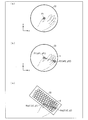
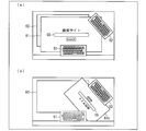
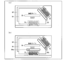
- FIG. 1 It is a functional block diagram which shows the outline of a structure of the information processing apparatus which concerns on one embodiment of this invention. It is explanatory drawing which shows an example of the external appearance of the touch screen display with which the information processing apparatus shown in FIG. 1 is provided. (A)-(c) is explanatory drawing which shows the outline
- FIG. 2 is an explanatory diagram illustrating an example of a virtual input device other than a virtual keyboard displayed by the information processing apparatus illustrated in FIG. 1, where (a) illustrates a virtual numeric keypad and (b) illustrates a virtual touchpad.
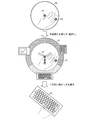
- FIG. 2 is an explanatory diagram illustrating a method of selecting a virtual input device to be displayed from a plurality of types of virtual input devices in the information processing apparatus illustrated in FIG. 1.
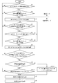
- 3 is a flowchart showing a flow of processing for selecting a virtual input device to be displayed from a plurality of types of virtual input devices in the information processing apparatus shown in FIG. 1.
- (A)-(c) is explanatory drawing which shows the example of the pattern of an application screen at the time of the information processing apparatus shown in FIG.
- FIG. 1 displaying a virtual keyboard.
- (A)-(c) is explanatory drawing which shows the example of the form of the virtual keyboard which the information processing apparatus shown in FIG. 1 displays. It is explanatory drawing which shows the example of a display of the virtual keyboard displayed on the touchscreen display which concerns on the modification 1 of this invention.
- (A) And (b) is explanatory drawing which shows the example of a display of the virtual keyboard displayed on the touch screen display which concerns on the modification 3 of this invention.
- A)-(c) is explanatory drawing which shows the example of a display of the virtual keyboard displayed on the touch screen display which concerns on the modification 3 of this invention.
- (A) And (b) is explanatory drawing which shows the example of a display of the virtual keyboard displayed on the touch screen display which concerns on the modification 3 of this invention.
- (A) And (b) is explanatory drawing which shows the example of a display of the virtual keyboard displayed on the touch screen display which concerns on the modification 3 of this invention. It is explanatory drawing which shows the example of a display of the image displayed on a touchscreen display when inputting from the specific virtual keyboard. It is explanatory drawing which shows the example of a display of the image displayed on a touchscreen display when inputting from the specific virtual keyboard.
- FIG. 2 An example of the external appearance of the touch screen display 2 with which the information processing apparatus 1 which concerns on one Embodiment of this invention is provided is shown.
- the information processing apparatus 1 is an apparatus that includes at least a touch screen display 2 and displays virtual input devices such as virtual keyboards 31 and 32 for a user to perform operation input on the touch screen display 2.
- virtual input devices such as virtual keyboards 31 and 32 for a user to perform operation input on the touch screen display 2.
- a created keyboard may be distinguished as a virtual keyboard 31, and a newly created keyboard as a virtual keyboard 32.
- the touch screen display 2 of the information processing apparatus 1 includes a transparent touch panel 2T (FIG. 1) disposed on a display surface of an LCD (Liquid Crystal Display) 2D (FIG. 1), and is realized by the LCD 2D and the touch panel 2T. Yes.
- a transparent touch panel 2T for example, a resistance film method or a capacitance method can be used.
- a multi-touch panel that can simultaneously detect a plurality of touch positions may be used as the touch panel 2T.
- the touch screen display 2 is configured such that the touch panel 2T can detect the touch position on the display screen of the LCD 2D touched by the user with a pen or a finger. Coordinate data indicating the touch position on the display screen of the touch screen display 2 is input from the touch screen display 2 to a processing unit described later in the information processing apparatus 1. Thereby, the user can select various objects (for example, icons representing folders and files, menus, buttons, and the like) displayed on the display screen of the LCD 2D using a fingertip or a pen.
- objects for example, icons representing folders and files, menus, buttons, and the like
- the touch screen display 2 can display a virtual keyboard 31 (also referred to as a software keyboard).
- the virtual keyboard 31 includes a plurality of virtual keys (also referred to as software buttons) for inputting a plurality of key codes. More specifically, the virtual keys are numeric keys, alphabet keys, arrow keys, function keys, and other auxiliary keys.
- the user touches the virtual key of the virtual keyboard 31 displayed on the LCD 2D via the touch panel 2T, thereby causing various code data (key code, character code, command, etc.) to be displayed on the application window displayed on the LCD 2D. Etc.) can be entered.
- the information processing apparatus 1 allows a plurality of people to operate the touch screen display 2 simultaneously from different directions. That is, on the touch screen display 2 of the information processing apparatus 1, a plurality of users can generate and display virtual keyboards 31 and 32 in accordance with the size and orientation of their hands. Specifically, when the first user displays and uses his / her virtual keyboard 31 on the touch screen display 2, the second user generates his / her virtual keyboard 32 on the touch screen display 2. Can be displayed.
- the virtual keyboards 31 and 32 can be changed to different sizes, orientations, and positions after being displayed once.
- the virtual input device to be displayed on the touch screen display 2 may be a virtual numeric keypad or a virtual touch pad in addition to a virtual keyboard, but is not limited to this, and a shape such as a size on the touch screen display 2 may be used. Any change can be applied as long as it can be changed for each user.
- the form of the virtual input device displayed on the touch screen display 2 may be a general-purpose form that does not limit the application, but may be a dedicated form so as to be used in a specific application.
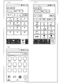
- a TV remote control key (FIG. 11A), a smart phone touch panel (FIG. 11B), a BD recorder operation key (FIG. 11C), etc.
- FIG. 1 is a functional block diagram showing an outline of the configuration of the information processing apparatus 1.
- the information processing apparatus 1 includes a touch screen display 2, a touch panel driver 3, a virtual input device control unit 4, an application unit 5, and a display driver 6.
- the touch screen display 2 includes the LCD (Liquid Crystal Display) 2D and the transparent touch panel 2T disposed on the upper surface of the LCD 2D.
- the touch panel 2T outputs a touch detection signal that detects a position touched by the user to the touch panel driver 3.
- the LCD 2D displays virtual input devices such as an application screen and virtual keyboards 31 and 32 via the display driver 6.
- the touch panel driver 3 generates coordinate data (touch position detection information) indicating the touch position on the touch screen display 2 from the touch detection signal from the touch panel 2T, and outputs the coordinate data to the virtual input device control unit 4.
- the application unit 5 receives the code data output from the virtual input device control unit 4 and processes it by a predetermined application.
- the display driver 6 displays virtual input devices such as the virtual keyboards 31 and 32 on the LCD 2D of the touch screen display 2 under the control of the virtual input device control unit 4.
- the display driver 6 displays an application screen on the LCD 2 ⁇ / b> D of the touch screen display 2 under the control of the application unit 5.
- the virtual input device controller 4 determines the type, size, orientation, position, etc. of the virtual input device and displays it on the LCD 2D of the touch screen display 2 via the display driver 6.
- the virtual input device control unit 4 includes a mode switching unit 11, a virtual key selection unit 12, a key assignment information storage unit 13, a code output unit 14, a virtual input device setting unit 15, a timer 16, a setting table storage unit 17, and a virtual table.
- An input device display unit (virtual input device display means) 18 is provided.
- the mode switching unit 11 switches the processing mode of the virtual input device control unit 4.
- the mode switching unit 11 transitions from the normal mode to the function creation mode when a predetermined touch operation described later is performed.
- the mode switching unit 11 outputs touch position detection information from the touch panel driver 3 to the virtual key selection unit 12 in the normal mode.
- the touch position detection information is output to the virtual input device setting unit 15.
- the virtual key selection unit 12 selects a virtual key touched by the user from a plurality of virtual keys of the virtual keyboard 31.
- the selection of the virtual key is performed by referring to the key assignment information stored in the key assignment information storage unit 13 based on the touch position detection information indicating the touch position.
- the key assignment information storage unit 13 stores key assignment information 13.
- key assignment information a correspondence relationship between an area on the touch screen display 2 where each of a plurality of virtual keys is displayed, that is, the position of the display area of each virtual key, and code data to be output is set in advance.
- the code output unit 14 outputs code data corresponding to the virtual key selected by the virtual key selection unit 12 to the application unit 5.
- the virtual input device setting unit 15 newly generates a virtual input device such as the virtual keyboard 32 and changes the position and shape.
- the virtual input device setting unit 15 stores setting information indicating the position, shape, and the like of the virtual input device for each user in association with the ID of the user who generated or changed the virtual input device. You may keep it.
- the virtual input device setting unit 15 acquires two designated points P1 and P2 designated on the touch panel 2T, and assigns each of the two designated points P1 and P2 to a virtual input device such as a virtual keyboard 32.
- the size, position and orientation of the virtual input device are determined so that the two reference points K1 and K2 set in advance match each other. That is, the virtual input device setting unit 15 determines the size of the virtual input device by expanding or reducing the distance between the reference points K1 and K2 of the virtual input device according to the distance between the two designated points P1 and P2.
- a virtual input device such as the virtual keyboard 32 on the touch screen display 2 in a shape that is easy for the user to use with a simple operation.
- the virtual input device setting unit 15 includes a designated point acquisition unit (designated point acquisition unit) 21, a shape determination unit (shape determination unit) 22, and a device selection unit (device selection unit) 23.
- the designated point acquisition unit 21 has two designated points P1 and P2 designated on the touch screen display 2 as the first designated point P1 designated as the first and the second designated point P2 designated as the second. And get it separately. Specifically, the designated point acquisition unit 21 obtains the predetermined range of the touch screen display 2 based on the first designated point P1 for a predetermined time (input available time t2) after obtaining the first designated point P1. In the second designated point input area 33 ((a) in FIG. 3), when the same position is designated for a predetermined time (long press time t3), the position is acquired as the second designated point P2.
- the shape determining unit 22 touches the touch screen so that the two reference points K1 and K2 set in advance on the virtual keyboard match the two specified points P1 and P2 acquired by the specified point acquiring unit 21, respectively.
- the size and position of the virtual keyboard 32 on the display 2 are determined.
- the shape determination unit 22 determines the orientation of the virtual keyboard 32 on the touch screen display 2 according to the relative positional relationship between the first designated point P1 and the second designated point P2.
- the two designated points P1 and P2 are distinguished into a first designated point P1 designated as the first and a second designated point P2 designated as the second, depending on the input operation.
- the two reference points K1 and K2 are distinguished into a first reference point K1 corresponding to the first specified point P1 and a second reference point K2 corresponding to the second specified point P2.
- the shape determination unit 22 associates the first reference point K1 with the first designated point P1 and associates the second designated point P2 with the second reference point K2, so that the size and position of the virtual keyboard 32 are simultaneously provided. Determine the orientation.
- the device selection unit 23 acquires a user operation to select a virtual input device to be displayed on the touch screen display 2 from a plurality of preset types (virtual keyboard 32, virtual numeric keypad 41, virtual touch pad 42).
- the timer 16 detects the touch time of the touch signal detected on the touch screen display 2 input to the mode switching unit 11 and the virtual input device setting unit 15. Specifically, the timer 16 is used for measuring the first long press time t1, the input possible time t2, and the second long press time t3. The first long press time t1, the input possible time t2, and the second long press time t3 can be arbitrarily set.
- the setting table storage unit 17 stores a setting table for the virtual input device setting unit 15 to refer to.
- the positions of the first reference point K1 and the second reference point K2 are set in advance for each type of virtual input device.
- the virtual input device display unit 18 displays the virtual keyboard 32 on the touch screen display 2 with the size and position determined by the shape determination unit 22.
- the virtual input device control unit 4 receives touch position detection information in the normal mode, and is touched by a user from a plurality of virtual keys in the virtual keyboard 31 based on the touch position detection information.
- the virtual key is selected, and based on the key assignment information 13, code data corresponding to the touch position detection information is output to the application unit 5.
- the virtual input device control unit 4 receives touch position detection information in the function creation mode, and based on the touch position detection information, the type, size, orientation, position, etc. of the virtual keyboard 32 to be displayed.
- the virtual keyboard 32 is displayed on the LCD 2D via the display driver 6 in the determined shape.
- FIG. 3 is an explanatory diagram showing an outline of a virtual keyboard setting method.
- FIG. 4 is an explanatory diagram showing two reference points set in the virtual keyboard.
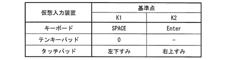
- FIG. 5 is a table showing an example of a setting table stored in the setting table storage unit 17.
- first long press time t1 when a touch operation for a predetermined time (first long press time t1) or more is performed at a certain position on the touch screen display 2 by a user's finger or the like, the position is displayed. While determining as the 1st designated point P1, the 2nd designated point input area 33 which is a circle centering on the touch position on the touch screen display 2 is displayed.
- a touch operation for a predetermined time (second long press time t3) or more with the user's other finger or the like in the displayed second designated point input area 33.
- the position is determined as the second designated point P2.
- a distance c between the first designated point P1 and the second designated point P2 is calculated.
- the virtual keyboard is set such that the distance c is a distance d between two reference points K1 and a second reference point (for example, center coordinates of the two keys Key1 and Key2) set in advance on the virtual keyboard.
- the size of 32 is determined ((c) of FIG. 3).
- the second designated point P2 can be input only within the second designated point input area 33 for a predetermined time (input possible time t2) after the first designated point P1 is inputted. Thereby, it can prevent malfunctioning by operation by persons other than the user who is going to set the virtual keyboard 32.
- FIG. 1 input possible time t2
- the position coordinates (xP1, yP1) of the first designated point P1 are the first reference points K1 (x1) which are the center coordinates of the key 1 of the virtual keyboard. , Y1), and the position coordinates (xP2, yP2) of the second designated point P2 correspond to the second reference point K2 (x2, y2) which is the center coordinate of the Key2.
- the first reference point K1 and the second reference point K2 are input to the first designated point P1 by the user with the right thumb
- the second designated point P2 can be set to be input with the right hand little finger.
- the first reference point K1 can be assigned to the center coordinate of the space key (Key1)
- the second reference point K2 can be assigned to the center coordinate of the enter key (Key2).
- the positions of the two reference points K1 and K2 on the virtual keyboard and the input method of the two designated points P1 and P2 are not limited to the above and can be arbitrarily selected.
- the virtual points P1 and P2 are stopped for a predetermined time (change determination long press time td) or more, as described above in [Overview of Virtual Keyboard Setting Method], the virtual points are set based on the positions of the designated points P1 and P2. The direction, size and position of the keyboard 31 are determined.
- the change start long press time ts and the change determination long press time td can be arbitrarily set.
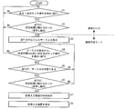
- FIG. 6 is a flowchart showing the flow of display processing of the virtual input device.
- the mode switching unit 11 acquires touch position detection information indicating the position coordinates (xP1, yP1) of the touch position P1 detected on the touch screen display 2 (S1).
- the timer 16 measures the duration of the touch operation at the touch position P1, and the touch operation is longer than the first long press time t1.
- the position is determined as the first designated point P1, and the second designated point input area 33, which is a circle with a predetermined radius centered on the touch position, is displayed on the touch screen display 2. (S3).
- the duration of the touch operation is less than the first long press time t1 (No in S2), the process proceeds to step S1.
- the second designated point input area 33 is displayed as a circular image on the touch screen display 2, so that the transition from the normal mode to the function creation mode is completed, the input of the first designated point P 1 is completed, the second designated point. It is possible to inform the user that P2 can be input and the input range of the second designated point P2.
- the mode switching unit 11 shifts from the normal mode to the function creation mode, and outputs the touch position detection information to the virtual input device setting unit 15. That is, as described above, the position coordinates (xP1, yP1) of the touch position P1 are output to the designation acquisition unit 21. Then, the designated point acquisition unit 21 sets the touch position P1 as the first designated point P1, and causes the virtual input device display unit 18 to select the second of the predetermined radius centered on the position coordinates (xP1, yP1) of the first designated point P1. The designated point input area 33 is displayed on the touch screen display 2 via the display driver 6. Thereafter, when a touch operation in the second designated point input area 33 is detected, the touch position detection information is also output from the mode switching unit 11 to the designation obtaining unit 21.
- the timer 16 measures the elapsed time from the display of the second designated point input area 33. Then, the touch position detection indicating the position coordinates (xP2, yP2) of the touch position P2 detected on the touch screen display 2 by the designated point acquisition unit 21 within the input possible time t2 from the display of the second designated point input area 33.
- the timer 16 measures the duration of the touch operation at the touch position P2. Start (S6).
- the position is determined as the second designated point P2, and the first designated point P1 and the second designated point are determined.
- the shape and the like of the virtual keyboard 32 are determined (S7; shape determination step). Specifically, as described above, the shape determining unit 22 touches each of the two designated points P1 and P2 so that the two reference points K1 and K2 set in advance on the virtual keyboard match each other. The size and position of the virtual keyboard 32 on the screen display 2 are determined. Then, the virtual input device display unit 18 displays the virtual keyboard 32 on the touch screen display 2 according to the determined size, orientation, and position (S8; virtual input device display step). The above steps S1 to S6 correspond to the designated point acquisition step.
- the designated point acquisition unit 21 displays the virtual input device display.
- the display of the second designated point input area 33 displayed on the screen display 2 is stopped in the unit 18, and the process proceeds to step S1.
- the touch position P2 is outside the second designated point input area 33 (No in S5), and the duration of the touch operation at the touch position P2 is the second long press. If it is less than time t3 (No in S6), the process proceeds to step S4 and waits for detection of a new touch position P2.
- FIG. 7 is an explanatory diagram illustrating an example of a virtual input device other than a virtual keyboard, where (a) illustrates a virtual numeric keypad and (b) illustrates a virtual touchpad.
- the first reference point K ⁇ b> 1 and the second reference point K ⁇ b> 2 are input to the first designated point P ⁇ b> 1 by the right thumb by the user, Is set to input the second designated point P2.
- the first reference point K1 is assigned to the center coordinates of the “0” key (Key1)
- the second reference point K2 is assigned to the center coordinates of the “ ⁇ ” key (Key2).
- the first reference point K ⁇ b> 1 and the second reference point K ⁇ b> 2 are input to the first designated point P ⁇ b> 1 by the user with the right thumb.
- the second designated point P2 is set to be input by the right hand index finger.
- the first reference point K1 is assigned to the lower left corner of the touch area and the upper right corner of the touch area.
- the virtual input device displayed on the touch screen display 2 is not limited to a virtual keyboard, a virtual numeric keypad, and a virtual touch pad, and can change the shape such as the size on the touch screen display 2 for each user. If so, it can be arbitrarily applied. Further, the positions of the two reference points K1 and K2 in each virtual input device and the input method of the two designated points P1 and P2 are not limited to the above and can be arbitrarily selected.
- FIG. 8 is an explanatory diagram illustrating a method of selecting a virtual input device to be displayed from a plurality of types of virtual input devices in the information processing apparatus 1.
- FIG. 9 is a flowchart illustrating a flow of processing for selecting a virtual input device to be displayed from a plurality of types of virtual input devices in the information processing apparatus 1.
- Steps S1 to S6 and S7 to S8 in the flowchart shown in FIG. 9 are the same as steps S1 to S6 and S7 to S8 in the flowchart shown in FIG. 6 described above in [Detailed flow of display method of virtual keyboard]. Therefore, the repeated explanation is not described here.
- the device selection unit 23 replaces the second designated point input area 33 with a device selection circle 34 via the virtual input device display unit 18. It is displayed on the display 2 (S9).
- the device selection circle 34 has, for example, a circular shape centered on the first designated point P1.
- the entire circumference of the device selection circle 34 is divided into arcs of the number of selectable virtual input devices, and selectable virtual input devices are assigned to the respective arcs. Then, the user can select the virtual input device assigned to the arc approaching the first designated point P1 by bringing the touch of the first designated point P1 closer to any arc.
- the user can select a virtual input device by selecting any arc of the device selection circle 34 or an icon of a virtual input device assigned to the arc.
- the touch of the first designated point P1 is moved in the direction of the virtual input device to be selected, or once the finger or the like is touched on the touch screen display 2. Touch the icon of the virtual input device you want to select.
- the device selection unit 23 measures the elapsed time from the display of the device selection circle 34 by the timer 16.
- the device selection unit 23 detects that the touch of the first designated point P1 is released from the touch screen display 2 within a predetermined time (first device selection time t4) from the display of the device selection circle 34 (in S10) Yes)
- the moving direction of the touch position is calculated, and the first designated point P1 is any of the device selection circles 34. It is determined whether or not the arc has approached, and the selected virtual input device is determined (S12-1). In the example of FIG. 8, since the first designated point P1 has moved downward in the drawing of the device selection circle 34, it is determined that the virtual keyboard assigned to the arc positioned ahead in the movement direction has been selected.
- the device selection circle 34 is within a predetermined time (second device selection time t5) after the touch is released.
- the selection operation for one of the arcs or the icon of the virtual input device assigned to the arc is acquired, and the selected virtual input device is determined (S12-2).
- the shape determining unit 22 determines the shape and the like of the virtual input device such as the virtual keyboard 32 based on the first designated point P1 acquired in step S2 and step S6 (S7; shape determining step). Then, the virtual input device display unit 18 displays the selected type of virtual input device on the touch screen display 2 according to the determined size, orientation, and position (S8; virtual input device display step).
- step S1 when the device selection unit 23 does not detect that the touch of the first designated point P1 has been released from the touch screen display 2 within the first device selection time t4 from the display of the device selection circle 34 (in S10) No), and if the selection operation of the icon of the virtual input device is not performed on the device selection circle 34 within the second device selection time t5 (No in S12-2), the process proceeds to step S1.
- the first device selection time t4 and the second device selection time t5 can be arbitrarily set.
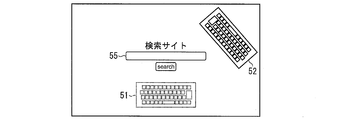
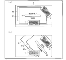
- FIG. (A) to (c) of FIG. 10 are explanatory diagrams showing examples of application screen patterns when displaying a virtual keyboard.
- input to the application screen is managed exclusively for the plurality of virtual keyboards 51 and 52.
- the new virtual keyboard 52 may not be created.
- the display screen of the application unit 5 is fixed to the touch screen display 2 and is not changed. Good.
- the display screen of the application unit 5 is displayed in accordance with the orientation of the virtual keyboard 51.
- the display screen of the application unit 5 is matched with the position and orientation of the virtual keyboard 52, You may display so that the user of the virtual keyboard 52 can see easily.
- the display screen 53 of the application unit 5 is rotated, reduced or enlarged and displayed near the virtual keyboard 52.
- the virtual input device display unit 18 starts input from the virtual keyboard 52
- the character string input from the virtual keyboard 52 is displayed in the display screen of the application unit 5. You may display the state which is displayed.
- an input window 54 is displayed according to the position and orientation of the virtual keyboard 52 so that the user of the virtual keyboard 52 can easily see.
- the input window 54 is displayed in a balloon shape so that it can be seen that the character string or the like input to the input window 54 is input to the input box 55 of the application unit 5.
- FIG. 12 shows a virtual keyboard 51 and a virtual keyboard 52 displayed on the touch screen display 2 in this modification. Although two virtual keyboards are shown in FIG. 12, the number of virtual keyboards is not particularly limited.
- start input means that the input box 55 on the display screen of the application unit 5 has focus and one or more confirmed characters have been entered in the input box 55 or a temporary character before confirmation. A state in which characters are displayed in the input box 55. When all the character strings and the like input from the specific virtual keyboard to the input box 55 are deleted by the DEL key and the BS key, the input state is not set.
- the virtual keyboard 51 and the virtual keyboard 52 as shown in FIG.
- the input from the virtual keyboard 51 becomes impossible. That is, the virtual keyboard 51 receives exclusive control.
- the virtual keyboard 52 confirms the input character string in the input box 55 and confirms the input to the input box 55 with the ENTER key or the like, the virtual keyboard 51 that cannot be input can be input. Also good.
- the display of the virtual keyboard 51 that has received the exclusive control may be changed.
- the virtual keyboard 51 that has undergone exclusive control is displayed with a dotted line, but the virtual keyboard that has undergone exclusive control may be displayed in gray or may be input, for example.
- the display form is not particularly limited as long as the virtual keyboard subjected to the exclusive control can be distinguished from the virtual keyboard that can be input.
- the virtual keyboard that is under exclusive control is also displayed as a dotted line in the diagrams for explaining other modified examples, but the virtual keyboard that is not being input is also not controlled exclusively and is in a state where input is possible, and a solid line May be displayed.
- the virtual keyboard that receives the above exclusive control, only a part of the keys may not be input.
- the keys described above there are keys involved in character input.
- special keys such as function keys that are not involved in character input may be input.
- the display of only the keys for which some inputs are impossible may be changed as described above so that the keys can be distinguished from the keys that can be input.
- the exclusive control of the other virtual keyboard 51 is released.
- the display of the virtual keyboard 51 that has received the exclusive control returns to the display before the exclusive control.
- the user who has started the input can input it without any intervention from the input of the other person during the input. Further, by changing the display of the virtual keyboard 51 that has received exclusive control, the user of the virtual keyboard 51 that has received exclusive control can recognize the release of exclusive control. Therefore, it is possible to smoothly prompt the user to input.
- a configuration in which exclusive control of other virtual keyboards 51 is not performed while a specific virtual keyboard 52 is being input may be employed.
- the other person can support the character input of a specific user on the way. Moreover, it is possible to input without confusion by considering the other party on the same touch panel.
- Display example 1 An example of image display at the time of input from the virtual keyboard will be described with reference to FIG.
- members having the same functions as those described in the embodiment, the first modification, and the second modification are denoted by the same reference numerals and description thereof is omitted.
- FIG. 13 shows a display screen displayed on the touch screen display 2 in this display example.
- (A) in FIG. 13 is a display example of an image displayed on the touch screen display 2 when there is no virtual keyboard being input. That is, all virtual keyboards are waiting for input.
- the touch screen display 2 displays a virtual keyboard 51, a virtual keyboard 52, and a display screen Q other than the virtual keyboard.
- the display screen Q includes a window 61 having an input box 55 displayed by the application unit 5 and other windows 62.
- the number of windows 62 that do not include the input box 55 is not particularly limited.
- (B) of FIG. 13 is a display example of an image displayed on the touch screen display 2 when inputting from a specific virtual keyboard.
- the display screen Q is rotated without changing the size of the display screen according to the position and orientation of the virtual keyboard 52, and the display screen is changed.
- the display screen is Q1.
- the display screen Q1 includes a window 61a and a window 62a obtained by rotating the window 61 and the window 62 in the same manner as the display screen Q1.
- the window 61a the entire area of the input box 55 is displayed on the touch screen display 2.
- the input with the virtual keyboard is temporary, and if the entire area of the input box 55 can be displayed, a part of the display screen Q including the window 61a may protrude beyond the display area of the touch screen display 2, or the virtual keyboard 51, It is not a problem even if it is overlaid on 52 and invisible.
- the input box 55 can be displayed so that the user who performs the input can easily see.
- FIG. 14 shows a display screen displayed on the touch screen display 2 in this display example.
- (A) of FIG. 14 is a display example of an image displayed on the touch screen display 2 when the virtual keyboard to be input is not fixed.
- the touch screen display 2 displays a virtual keyboard 51, a virtual keyboard 52, and a display screen Q other than the virtual keyboard.
- the display screen Q includes a window 61 having an input box 55 displayed by the application unit 5 and other windows 62.
- FIG. 14B is a display example of an image displayed on the touch screen display 2 when a specific virtual keyboard starts input.
- the display screen Q is rotated and reduced, and the entire display screen Q is displayed near the virtual keyboard 52 as the display screen Q2. .
- Display screen Q2 includes window 61 and window 62 in which window 61 and window 62 are rotated and reduced in the same manner as display screen Q1.
- the user of the virtual keyboard 52 can continuously perform character input and subsequent operations in an easy-to-see manner.
- (C) of FIG. 14 is a display example of another image displayed on the touch screen display 2 when a specific virtual keyboard is input.
- the display screen Q when the specific virtual keyboard 52 is input, the display screen Q is rotated and reduced and displayed as the display screen Q3.
- the input box 55 On the display screen Q3, at least the input box 55 is displayed at a position where both users of the virtual keyboard 51 and the virtual keyboard 52 can easily see.
- the screen tilt and position of the display screen Q3 are displayed so as to be intermediate between the virtual keyboard 51 and the virtual keyboard 52.
- FIG. 15 shows a display screen displayed on the touch screen display 2 in this display example.
- FIG. 15 shows a display example of an image displayed on the touch screen display 2 when a virtual keyboard for input is not fixed.
- the touch screen display 2 displays a virtual keyboard 51, a virtual keyboard 52, and a display screen Q other than the virtual keyboard.
- the display screen Q includes a window 61 having an input box 55 displayed by the application unit 5 and other windows 62.
- FIG. 15 shows a display example of an image displayed on the touch screen display 2 when a specific virtual keyboard starts input.
- the window 61 which is an active window for inputting characters, is rotated and displayed as a window 61b on the front of the virtual keyboard 52.
- a reduced version of the window 61 may be rotated and displayed as the window 61b. If the entire area of the input box 55 can be displayed, a part of the display screen Q including the window 61a is displayed on the display area of the touch screen display 2. It does not matter if it protrudes outside or is not visible because it is superimposed on the virtual keyboards 51 and 52.
- FIG. 16 shows a display example of an image displayed on the touch screen display 2 when inputting a specific virtual keyboard in this display example.
- the touch screen display 2 displays a virtual keyboard 51, a virtual keyboard 52, a window 61 including an input box 55 displayed by the application unit 5, and other windows 62.
- an input window 64 is displayed adjacent to the vicinity of the virtual keyboard 52 being input.
- the layout of the entire screen is not changed, and all users can continue to view the input window that is the target of character input without any problem. Furthermore, the user who inputs characters can comfortably perform input work while referring to the characters input to the input window.
- the input windows 64a and 64b may be displayed in adjacent areas of both virtual keyboards 51 and 52.
- exclusive control may not be applied to a virtual keyboard other than the virtual keyboard that is performing the input. In this case, it is possible to input independently from the virtual keyboards 51 and 52 to the input windows 64a and 64b.
- the character strings in the input windows 64a and 64b are transferred to the original input window.
- (Modification 4) Display example in the case where there are a plurality of input boxes in the display screen of the application in which a character string or the like can be input from the virtual keyboard
- FIGS. 17 and 18 the virtual input device display unit 18 A display example showing how a character string or the like input from the virtual keyboard is displayed in the display screen of the application unit 5 will be described.
- members having the same functions as those described in the embodiment, the first modification, the second modification, and the third modification are denoted by the same reference numerals and the description thereof is omitted.
- FIG. 17 shows a display example of an image displayed on the touch screen display 2 when a specific virtual keyboard starts input.
- the touch screen display 2 displays a virtual keyboard 51, a virtual keyboard 52, a window 71 including a plurality of input boxes including an input box 73 displayed by the application unit 5, and other windows 72. Is done.
- the number of windows 72 that do not include an input box is not particularly limited.
- an input window 64c is displayed so that the user of the virtual keyboard 52 can easily see.
- the input window 64c is displayed in a balloon shape so that it can be seen that a character string or the like input to the input window 64c is input to a certain input window 73 among the plurality of input windows of the application unit 5.
- the state of input to the input box displayed by the application unit 5 can be clearly shown in association with the virtual keyboard. Therefore, even in the case of an application having a plurality of input boxes, it is possible to input characters accurately.
- FIG. 18 shows another display example of an image displayed on the touch screen display 2 when a specific virtual keyboard starts input.
- the touch screen display 2 displays a virtual keyboard 51, a virtual keyboard 52, a window 76 having a plurality of input boxes including an input box 74 displayed by the application unit 5, and other windows 77. Is done.
- an input window 64 d is displayed in an adjacent area of the virtual keyboard 52.
- a frame 75 is displayed around the input box 74 so that a character string or the like input to the input window 64d is input to the input box 74 among the plurality of input boxes of the application unit 5.
- the frame 75 and the input window 64d do not have a continuous area on the image display like the balloon of the input window 64c shown in FIG.
- the above-described information processing apparatus 1 can be widely applied to information devices equipped with a touch screen display such as a television receiver, a personal computer, an electronic white board, digital signage, a remote control device, a smart phone, a mobile phone, and other portable terminals. . These information devices including the information processing apparatus 1 are also included in the category of the invention described in this specification.
- the touch screen display of the information processing apparatus 1 can be realized by a configuration in which a transparent touch panel member is disposed on a display surface of an LCD (liquid crystal display device).
- the present invention is not limited to this, and may be realized by a configuration in which a part of the touch sensor function is provided inside the LCD pixel or a configuration in which the touch sensor function is integrally provided on the color filter substrate of the LCD body.
- each block of the information processing apparatus 1, particularly the virtual input device control unit 4 may be configured by hardware logic, or may be realized by software using a CPU as follows.
- the information processing apparatus 1 includes a CPU (central processing unit) that executes instructions of a program that implements each function, a ROM (read only memory) that stores the program, and a RAM (random access memory that expands the program). ), A storage device (recording medium) such as a memory for storing the program and various data.
- An object of the present invention is to provide a recording medium in which a program code (execution format program, intermediate code program, source program) of a control program of the information processing apparatus 1 which is software for realizing the above-described functions is recorded so as to be readable by a computer. This can also be achieved by supplying the information processing apparatus 1 and reading and executing the program code recorded on the recording medium by the computer (or CPU or MPU).
- Examples of the recording medium include tapes such as magnetic tapes and cassette tapes, magnetic disks such as floppy (registered trademark) disks / hard disks, and disks including optical disks such as CD-ROM / MO / MD / DVD / CD-R.
- Card system such as IC card, IC card (including memory card) / optical card, or semiconductor memory system such as mask ROM / EPROM / EEPROM (registered trademark) / flash ROM.
- the information processing apparatus 1 may be configured to be connectable to a communication network, and the program code may be supplied via the communication network.
- the communication network is not particularly limited.
- the Internet intranet, extranet, LAN, ISDN, VAN, CATV communication network, virtual private network, telephone line network, mobile communication network, satellite communication. A net or the like is available.
- the transmission medium constituting the communication network is not particularly limited.
- wired such as IEEE 1394, USB, power line carrier, cable TV line, telephone line, ADSL line, etc.
- infrared rays such as IrDA and remote control, Bluetooth (Registered trademark), 802.11 wireless, HDR, mobile phone network, satellite line, terrestrial digital network, and the like can also be used.
- the present invention can also be realized in the form of a computer data signal embedded in a carrier wave in which the program code is embodied by electronic transmission.
- an information processing apparatus includes a touch screen display, and displays a virtual input device for a user to perform an operation input on the touch screen display.
- the virtual input device is set in advance for each of the specified point acquisition means for acquiring the two specified points specified on the touch screen display and the two specified points acquired by the specified point acquisition means.
- Shape determining means for determining the size and position of the virtual input device in the touch screen display so that each of the two reference points matches, and the virtual input device with the size and position determined by the shape determining means Virtual input device display means for displaying on the touch screen display. It is characterized in Rukoto.
- a method for controlling an information processing apparatus comprising: a touch screen display; A designated point acquisition step for obtaining two designated points designated on the screen display, and two of the two designated points obtained in the designated point obtaining step are set in advance in the virtual input device.
- a shape determining step for determining the size and position of the virtual input device on the touch screen display so that each of the reference points matches, and the virtual input device at the size and position determined in the shape determining step.
- Virtual input device display screen displayed on the touch screen display Tsu is characterized in that it comprises a flop, the.
- the information processing apparatus acquires two designated points designated on the touch screen display, and two reference points set in advance in the virtual input device for each of the two designated points.
- the size and position of the virtual input device on the touch screen display are determined so that each of these matches. Then, the virtual input device is displayed on the touch screen display according to the determined size and position.
- the position of the virtual input device to be displayed can be determined as the position of the designated point.
- the size of the virtual input device to be displayed is determined by determining the degree of scaling of the virtual input device so that the distance between the two designated points matches the distance between the two reference points of the virtual input device. be able to.
- the desired position of the user can be obtained. And the virtual input device can be displayed in size.
- the virtual input device can be displayed on the touch display at a position and size easy for the user to use by a simple operation of inputting two designated points on the touch screen display.
- the designated point acquisition unit acquires the first designated point designated as the first and the second designated point designated as the second.
- the shape determining means determines the orientation of the virtual input device on the touch screen display according to the relative positional relationship between the first designated point and the second designated point. Yes.
- the information processing apparatus further acquires the two specified points by distinguishing the first specified point specified as the first from the second specified point specified as the second.
- the orientation of the virtual input device on the touch screen display is determined according to the relative positional relationship between the first designated point and the second designated point.
- the relative positional relationship between the two designated points can be determined as one.
- the orientation of the virtual input device on the touch screen display can be determined.
- the user when the user inputs two specified points on the touch screen display, for example, by inputting the second specified point after inputting the first specified point, the user enters the touch screen display.
- the direction of the virtual input device to be displayed can be designated.
- the virtual input device can be displayed on the touch display in a user-friendly direction by a simple operation of distinguishing and inputting two designated points on the touch screen display.
- the specified point acquisition unit is the same for a predetermined time within a predetermined range of the touch screen display with the first specified point as a reference after acquiring the first specified point.
- the position is acquired as the second designated point.
- the information processing apparatus when the information processing apparatus further specifies the same position for a predetermined time within a predetermined range of the touch screen display with the first specified point as a reference after acquiring the first specified point.
- the position is acquired as the second designated point. That is, the second designated point is detected as a long press operation within a limited range.
- the “predetermined time” is set to a time when the user who has input two specified points does not have an excess or deficiency to clearly indicate the intention to input the second specified point.
- the information processing apparatus changes the arrangement of all or part of an image displayed on the touch screen display simultaneously with the virtual input device in accordance with the display of the virtual input device on the touch screen display. It is characterized by that.
- the image displayed simultaneously with the virtual input device can be displayed so that the user who performs the input can easily see.
- the information processing apparatus is configured to display a plurality of virtual input devices on the touch screen display while the user performs an operation input using one virtual input device, and the like.
- the virtual input device is configured such that a user cannot perform an operation input.
- the user who has started input can input exclusively during input. In other words, it is possible to input with peace of mind without receiving intervention from others.
- the information processing apparatus further includes device selection means for acquiring a user operation for selecting the virtual input device to be displayed on the touch screen display from a plurality of preset types. Yes.
- the information processing apparatus further acquires a user operation for selecting a virtual input device to be displayed on the touch screen display from a plurality of preset types.
- a virtual keyboard for example, a virtual keyboard, a virtual numeric keypad, and a virtual touchpad can be considered.
- the present invention is not limited to this, and can be arbitrarily applied as long as the shape such as the size can be changed.
- the user can select and display a virtual input device to be displayed from a plurality of types of virtual input devices.
- an electronic white board according to the present invention is characterized by including the above information processing apparatus.
- a television receiver according to the present invention is characterized by including the above information processing apparatus.
- the virtual input device can be displayed in a user-friendly shape on the screen (touch screen display) of the television receiver with a simple operation.
- the digital signage according to the present invention is characterized by including the above-described information processing apparatus.
- the information processing apparatus may be realized by a computer.
- an information processing apparatus control program for causing the information processing apparatus to be realized by the computer by causing the computer to operate as the above-described means, and A computer-readable recording medium on which is recorded also falls within the scope of the present invention.
- the present invention can display a virtual input device such as a virtual keyboard on a touch screen display in a user-friendly shape by a simple operation, a TV, a personal computer, an electronic white board, a digital signage, a remote control device, It can be widely used in information devices equipped with touch screen displays such as smart phones, mobile phones, and other mobile terminals.
Landscapes
- Engineering & Computer Science (AREA)
- General Engineering & Computer Science (AREA)
- Theoretical Computer Science (AREA)
- Human Computer Interaction (AREA)
- Physics & Mathematics (AREA)
- General Physics & Mathematics (AREA)
- User Interface Of Digital Computer (AREA)
- Position Input By Displaying (AREA)
- Input From Keyboards Or The Like (AREA)
Abstract
タッチスクリーンディスプレイ画面に簡便な操作で、使用者の使いやすい形状で仮想入力装置を表示する。 情報処理装置1は、タッチスクリーンディスプレイ(2)で指定された2つの指定点を取得する指定点取得部(21)と、2つの指定点のそれぞれに、仮想入力装置にあらかじめ設定されている2つの基準点のそれぞれが一致するように、仮想入力装置の大きさ、位置、および向き決定する形状決定部(22)とを備える。
Description
本発明は、仮想入力装置を表示することが可能なタッチスクリーンディスプレイを搭載した情報処理装置、情報処理装置の制御方法、制御プログラム、コンピュータ読み取り可能な記録媒体に関する。
スマートホンなど、タッチパネルで操作する電子機器が増えてきており、電子黒板やTV会議システムなどタッチパネルが搭載された大型の表示装置も導入されている。特に近年、80インチを超える大型サイズのタッチスクリーンディスプレイを備えたテレビ受像機やデジタルサイネージも商品化されてきている。一方で、タッチスクリーンディスプレイ上に置かれた使用者の手の大きさに対応した大きさで、複数の仮想キーを含み、仮想キーのコードデータを出力する仮想キーボードをタッチスクリーンディスプレイに表示できる技術が開発されている。
例えば、特許文献1には、タッチスクリーンディスプレイ上に置かれた使用者の手の大きさを検出し、検出された大きさに応じた大きさの仮想キーボードを表示する情報処理装置が開示されている。詳細には、上記情報処理装置は、タッチスクリーンディスプレイと、前記タッチスクリーンディスプレイからの検出信号に応じて、前記タッチスクリーンディスプレイ上に置かれた使用者の手の大きさを検出する検出手段と、キーコードをそれぞれ入力するための複数の仮想キーを含む仮想キーボードを前記タッチスクリーンディスプレイ上に表示する仮想キーボード表示手段であって、前記検出手段によって検出された大きさに応じた大きさの前記仮想キーボードを表示する表示手段と、前記仮想キーボードの内の操作された仮想キーに対応するコードデータを出力する出力手段を具備する。
しかしながら、上記従来の構成では、入力を開始するまでに、キーボードを「表示させる」、「移動する」、「大きさを調整する」といった数段階の動作を必要とするので、作業効率が損なわれてしまうという問題を生じる。具体的には、特許文献1の情報処理装置では、使用者の手の大きさを検出するために両手を使用する必要があり、合わせて10か所のポイントをタッチパネルで認識しなければならない。
また、近時、タッチパネルを複数人で四方から同時に操作する場面も想定され、操作性の向上が必要である。しかしながら、上記従来の構成では、そのような課題は考慮されていない。
本発明は、上記の問題点に鑑みてなされたものであり、その目的は、タッチスクリーンディスプレイ画面に簡便な操作で、使用者の使いやすい形状で仮想入力装置を表示することができる情報処理装置、情報処理装置の制御方法、制御プログラム、コンピュータ読み取り可能な記録媒体を実現することにある。
上記の課題を解決するために、本発明に係る情報処理装置は、タッチスクリーンディスプレイを備え、使用者が操作入力を行うための仮想入力装置を上記タッチスクリーンディスプレイに表示する情報処理装置において、上記タッチスクリーンディスプレイ上で指定された2つの指定点を取得する指定点取得手段と、上記指定点取得手段が取得した上記2つの指定点のそれぞれに、上記仮想入力装置にあらかじめ設定されている2つの基準点のそれぞれが一致するように、上記タッチスクリーンディスプレイにおける上記仮想入力装置の大きさおよび位置を決定する形状決定手段と、上記形状決定手段が決定した大きさおよび位置で上記仮想入力装置を上記タッチスクリーンディスプレイに表示する仮想入力装置表示手段と、を備えることを特徴としている。
また、本発明に係る情報処理装置の制御方法は、タッチスクリーンディスプレイを備え、使用者が操作入力を行うための仮想入力装置を上記タッチスクリーンディスプレイに表示する情報処理装置の制御方法において、上記タッチスクリーンディスプレイ上で指定された2つの指定点を取得する指定点取得ステップと、上記指定点取得ステップにて取得した上記2つの指定点のそれぞれに、上記仮想入力装置にあらかじめ設定されている2つの基準点のそれぞれが一致するように、上記タッチスクリーンディスプレイにおける上記仮想入力装置の大きさおよび位置を決定する形状決定ステップと、上記形状決定ステップにて決定した大きさおよび位置で上記仮想入力装置を上記タッチスクリーンディスプレイに表示する仮想入力装置表示ステップと、を含むことを特徴としている。
以上より、本発明に係る情報処理装置は、タッチスクリーンディスプレイ上で指定された2つの指定点を取得する指定点取得手段と、上記指定点取得手段が取得した上記2つの指定点のそれぞれに、仮想入力装置にあらかじめ設定されている2つの基準点のそれぞれが一致するように、上記タッチスクリーンディスプレイにおける上記仮想入力装置の大きさおよび位置を決定する形状決定手段と、上記形状決定手段が決定した大きさおよび位置で上記仮想入力装置を上記タッチスクリーンディスプレイに表示する仮想入力装置表示手段と、を備える構成である。
また、本発明に係る情報処理装置の制御方法は、タッチスクリーンディスプレイ上で指定された2つの指定点を取得する指定点取得ステップと、上記指定点取得ステップにて取得した上記2つの指定点のそれぞれに、仮想入力装置にあらかじめ設定されている2つの基準点のそれぞれが一致するように、上記タッチスクリーンディスプレイにおける上記仮想入力装置の大きさおよび位置を決定する形状決定ステップと、上記形状決定ステップにて決定した大きさおよび位置で上記仮想入力装置を上記タッチスクリーンディスプレイに表示する仮想入力装置表示ステップと、を含む方法である。
それゆえ、使用者が2つの指定点をタッチスクリーンディスプレイ上に、仮想入力装置を表示したい位置に、表示したい仮想入力装置の大きさを指定するように入力することにより、使用者の所望の位置および大きさで仮想入力装置を表示することができる。
よって、タッチスクリーンディスプレイ上に2つの指定点を入力するという簡便な操作により、使用者の使いやすい位置および大きさで仮想入力装置をタッチディスプレイに表示することができるという効果を奏する。
〔実施形態〕
以下、図1~図18を参照しながら、本発明の一実施の形態について詳細に説明する。
以下、図1~図18を参照しながら、本発明の一実施の形態について詳細に説明する。
〔情報処理装置の概要〕
図2に、本発明の一実施形態に係る情報処理装置1が備えるタッチスクリーンディスプレイ2の外観の一例を示す。
図2に、本発明の一実施形態に係る情報処理装置1が備えるタッチスクリーンディスプレイ2の外観の一例を示す。
情報処理装置1は、タッチスクリーンディスプレイ2を少なくとも備え、使用者が操作入力を行うための仮想キーボード31、32等の仮想入力装置をタッチスクリーンディスプレイ2に表示する装置である。なお、本実施の形態においては、タッチスクリーンディスプレイ2に表示する仮想キーボードのうち、作成済みのものを仮想キーボード31、新規に作成するものを仮想キーボード32として区別して示すことがある。
情報処理装置1のタッチスクリーンディスプレイ2は、LCD(液晶表示装置)2D(図1)の表示面に、透明のタッチパネル2T(図1)が配置されており、LCD2Dとタッチパネル2Tとによって実現されている。なお、タッチパネル2Tには、例えば、抵抗膜方式または静電容量方式等を用いることができる。また、タッチパネル2Tには、複数のタッチ位置を同時に検知可能なマルチタッチパネルを使用してもよい。
タッチスクリーンディスプレイ2は、使用者がペンまたは指によってタッチしたLCD2Dの表示画面上のタッチ位置を、タッチパネル2Tが検知可能に構成されている。タッチスクリーンディスプレイ2の表示画面上のタッチ位置を示す座標データは、タッチスクリーンディスプレイ2から情報処理装置1内の後述する処理部に入力される。これにより、使用者は、LCD2Dの表示画面上に表示された各種オブジェクト(例えば、フォルダやファイルを表すアイコン、メニュー、ボタン、等)を指先やペンなどを用いて選択することができる。
本実施の形態では、図2に示すように、タッチスクリーンディスプレイ2は、仮想キーボード31(ソフトウェアキーボードとも言う)の表示が可能である。この仮想キーボード31は、複数のキーコードをそれぞれ入力するための複数の仮想キー(ソフトウェアボタンとも言う)を含む。より詳しくは、仮想キーは、数字キー、アルファベットキー、矢印キー、ファンクションキー、その他の補助キー等である。使用者は、LCD2Dに表示される仮想キーボード31の仮想キーを、タッチパネル2Tを介してタッチ操作することにより、LCD2Dに表示されるアプリケーションウィンドウ等に対して各種コードデータ(キーコード、文字コード、コマンド等)を入力することができる。
また、情報処理装置1は、タッチスクリーンディスプレイ2を複数人が異なる方向から同時に操作することが可能である。すなわち、情報処理装置1のタッチスクリーンディスプレイ2には、複数の使用者がそれぞれ、自分の手の大きさおよび向きに合わせて、仮想キーボード31、32を生成し、表示することができる。具体的には、1人目の使用者がタッチスクリーンディスプレイ2に自分の仮想キーボード31を表示させて使用しているとき、2人目の使用者がタッチスクリーンディスプレイ2に自分の仮想キーボード32を生成して、表示することができる。そして、仮想キーボード31、32は、一度表示された後に、異なる大きさ、向きおよび位置に変更することができる。
なお、タッチスクリーンディスプレイ2に表示する仮想入力装置としては、仮想キーボードの他、仮想テンキーパッド、仮想タッチパッドが考えられるが、これに限定されず、タッチスクリーンディスプレイ2上における大きさ等の形状を使用者毎に変更可能なものであれば、任意に適用できる。また、タッチスクリーンディスプレイ2に表示する仮想入力装置の形態は、アプリケーションを限定しない汎用の形態であってもよいが、特定のアプリケーションで用いられるように専用の形態であってもよい。専用の形態の仮想入力装置としては、テレビのリモコンキー(図11の(a))、スマートホンのタッチパネル(図11の(b))、BDレコーダの操作キー(図11の(c))などが具体例として挙げられるが、これらに限られるものではない。
次に、図1を参照して、タッチスクリーンディスプレイ2に仮想入力装置を表示させるためのシステムの構成について説明する。図1は、情報処理装置1の構成の概略を示す機能ブロック図である。
〔仮想入力装置表示のための情報処理装置の構成〕
図1に示すように、情報処理装置1は、タッチスクリーンディスプレイ2、タッチパネルドライバ3、仮想入力装置制御部4、アプリケーション部5、表示ドライバ6を備えて構成されている。
図1に示すように、情報処理装置1は、タッチスクリーンディスプレイ2、タッチパネルドライバ3、仮想入力装置制御部4、アプリケーション部5、表示ドライバ6を備えて構成されている。
タッチスクリーンディスプレイ2は、上述のように、LCD(液晶表示装置)2Dと、LCD2Dの上面に配置されている透明のタッチパネル2Tから構成される。タッチパネル2Tは、使用者がタッチした位置を検出したタッチ検出信号をタッチパネルドライバ3に出力する。LCD2Dは、表示ドライバ6を介して、アプリケーション画面や仮想キーボード31、32等の仮想入力装置を表示する。
タッチパネルドライバ3は、タッチパネル2Tからのタッチ検出信号から、タッチスクリーンディスプレイ2上のタッチ位置を示す座標データ(タッチ位置検出情報)を生成して、仮想入力装置制御部4に出力する。
アプリケーション部5は、仮想入力装置制御部4から出力されたコードデータを受信し、所定のアプリケーションによって処理する。
表示ドライバ6は、仮想入力装置制御部4の制御に従って、仮想キーボード31、32等の仮想入力装置をタッチスクリーンディスプレイ2のLCD2Dに表示する。また、表示ドライバ6は、アプリケーション部5の制御に従って、アプリケーション画面をタッチスクリーンディスプレイ2のLCD2Dに表示する。
仮想入力装置制御部4は、仮想入力装置の種別、大きさ、向き、位置等の形状を決定して、表示ドライバ6を介して、タッチスクリーンディスプレイ2のLCD2Dに表示する。
そのため、仮想入力装置制御部4は、モード切り換え部11、仮想キー選択部12、キー割り当て情報記憶部13、コード出力部14、仮想入力装置設定部15、タイマー16、設定テーブル記憶部17、仮想入力装置表示部(仮想入力装置表示手段)18を備えて構成されている。
モード切り換え部11は、仮想入力装置制御部4の処理のモード切り換えを行う。モード切り換え部11は、後述する所定のタッチ操作が行われたとき、通常モードから機能作成モードに遷移する。モード切り換え部11は、通常モードのとき、タッチパネルドライバ3からのタッチ位置検出情報を仮想キー選択部12に出力する。一方、機能作成モードにおいては、タッチ位置検出情報を仮想入力装置設定部15に出力する。
仮想キー選択部12は、仮想キーボード31の複数の仮想キーから使用者によってタッチされた仮想キーを選択する。仮想キーの選択は、タッチ位置を示すタッチ位置検出情報に基づき、キー割当て情報記憶部13に記憶されているキー割当て情報を参照することにより行われる。
キー割当て情報記憶部13は、キー割り当て情報13を記憶している。キー割り当て情報には、複数の仮想キーそれぞれが表示されるタッチスクリーンディスプレイ2上の領域、つまり仮想キーそれぞれの表示領域の位置と、出力すべきコードデータとの対応関係があらかじめ設定されている。
コード出力部14は、仮想キー選択部12によって選択された仮想キーに対応するコードデータをアプリケーション部5に出力する。
仮想入力装置設定部15は、仮想キーボード32等の仮想入力装置の新規生成および位置や形状等の変更を行う。なお、仮想入力装置設定部15は、仮想入力装置の位置や形状等を示す設定情報を、その仮想入力装置を生成あるいは設定を変更した使用者のID等と対応付けて、使用者毎に記憶しておいてもよい。
具体的には、仮想入力装置設定部15は、タッチパネル2Tで指定された2つの指定点P1、P2を取得し、2つの指定点P1、P2のそれぞれに、仮想キーボード32等の仮想入力装置にあらかじめ設定されている2つの基準点K1、K2のそれぞれが一致するように、仮想入力装置の大きさ、位置、および向き決定する。すなわち、仮想入力装置設定部15は、2つの指定点P1、P2の距離に合わせて、仮想入力装置の基準点K1、K2の距離を拡縮させて仮想入力装置の大きさを決定する。これにより、簡便な操作で、使用者の使いやすい形状で仮想キーボード32等の仮想入力装置をタッチスクリーンディスプレイ2に表示することができる。
そのために、仮想入力装置設定部15は、指定点取得部(指定点取得手段)21、形状決定部(形状決定手段)22、装置選択部(装置選択手段)23を備える。
指定点取得部21は、タッチスクリーンディスプレイ2上で指定された2つの指定点P1、P2を、1つ目に指定された第1指定点P1と2つ目に指定された第2指定点P2とで区別して取得する。具体的には、指定点取得部21は、第1指定点P1の取得後、所定時間(入力可能時間t2)の間に、該第1指定点P1を基準とするタッチスクリーンディスプレイ2の所定範囲(第2指定点入力領域33(図3の(a)))内において、所定時間(長押し時間t3)、同じ位置が指定されたとき、当該位置を第2指定点P2として取得する。
形状決定部22は、指定点取得部21が取得した2つの指定点P1、P2のそれぞれに、仮想キーボードにあらかじめ設定されている2つの基準点K1、K2のそれぞれが一致するように、タッチスクリーンディスプレイ2における仮想キーボード32の大きさおよび位置を決定する。また、形状決定部22は、第1指定点P1と第2指定点P2との相対的位置関係に応じて、タッチスクリーンディスプレイ2における仮想キーボード32の向きを決定する。
具体的には、2つの指定点P1、P2を、入力操作の先後に応じて、1つ目に指定された第1指定点P1と2つ目に指定された第2指定点P2とに区別するとともに、2つの基準点K1、K2を、第1指定点P1に対応する第1基準点K1と第2指定点P2に対応する第2基準点K2とに区別しておく。そして、形状決定部22は、第1指定点P1に第1基準点K1を対応させ、第2指定点P2に第2基準点K2を対応させることにより、仮想キーボード32の大きさおよび位置と同時に、向きを決定する。
装置選択部23は、タッチスクリーンディスプレイ2に表示する仮想入力装置を、あらかじめ設定された複数種(仮想キーボード32、仮想テンキーパッド41、仮想タッチパッド42)から選択する使用者の操作を取得する。
さらに、タイマー16は、モード切り換え部11および仮想入力装置設定部15に入力された、タッチスクリーンディスプレイ2上で検出されたタッチ信号のタッチ時間を検出する。具体的には、タイマー16は、第1長押し時間t1、入力可能時間t2、第2長押し時間t3の計時に利用される。なお、第1長押し時間t1、入力可能時間t2、第2長押し時間t3は任意に設定できる。
設定テーブル記憶部17は、仮想入力装置設定部15が参照するための設定テーブルを記憶する。設定テーブルには、仮想入力装置の種別毎に、第1基準点K1および第2基準点K2の位置が対応付けて、あらかじめ設定されている。
仮想入力装置表示部18は、形状決定部22が決定した大きさおよび位置で仮想キーボード32をタッチスクリーンディスプレイ2に表示する。
上記の構成により、仮想入力装置制御部4は、通常モードのとき、タッチ位置検出情報を受信し、そのタッチ位置検出情報に基づいて、仮想キーボード31内の複数の仮想キーから使用者によってタッチされた仮想キーを選択し、キー割当て情報13に基づいて、当該タッチ位置検出情報に対応するコードデータをアプリケーション部5に出力する。また一方で、仮想入力装置制御部4は、機能作成モードのとき、タッチ位置検出情報を受信し、そのタッチ位置検出情報に基づいて、表示する仮想キーボード32の種類、大きさ、向き、位置等の形状を決定し、決定された形状で仮想キーボード32を表示ドライバ6を介して、LCD2Dに表示させる。
〔仮想キーボードの設定方法の概要〕
図3から5を参照して、使用者が使用しやすい大きさ、向きおよび位置に仮想キーボードを表示する方法の概要について説明する。図3は、仮想キーボードの設定方法の概要を示す説明図である。図4は、仮想キーボードに設定された2つの基準点を示す説明図である。図5は、設定テーブル記憶部17に記憶される設定テーブルの一例を示すテーブルである。
図3から5を参照して、使用者が使用しやすい大きさ、向きおよび位置に仮想キーボードを表示する方法の概要について説明する。図3は、仮想キーボードの設定方法の概要を示す説明図である。図4は、仮想キーボードに設定された2つの基準点を示す説明図である。図5は、設定テーブル記憶部17に記憶される設定テーブルの一例を示すテーブルである。
図3の(a)に示すように、タッチスクリーンディスプレイ2上のある位置に、使用者の指等により、所定時間(第1長押し時間t1)以上のタッチ操作が行われると、当該位置を第1指定点P1として決定するとともに、タッチスクリーンディスプレイ2上に、そのタッチ位置を中心とした円である第2指定点入力領域33を表示する。
次に、図3の(b)に示すように、表示された第2指定点入力領域33内に、使用者の別の指等により、所定時間(第2長押し時間t3)以上のタッチ操作が行われると、当該位置を第2指定点P2として決定する。そして、第1指定点P1および第2指定点P2の間の距離cを演算する。そして、距離cが、仮想キーボードにあらかじめ設定されている2つの基準点K1、第2基準点(例えば、2つのキーKey1、Key2のそれぞれの中心座標)間の距離dとなるように、仮想キーボード32の大きさを決定する(図3の(c))。
ここで、第2指定点P2の入力は、第1指定点P1の入力後の所定時間(入力可能時間t2)の間だけ、第2指定点入力領域33内に限って行えるようにする。これにより、仮想キーボード32を設定しようとしている使用者以外の者による操作によって、誤作動することを防止することができる。
図3の(b)(c)および図4に示されているように、第1指定点P1の位置座標(xP1,yP1)は仮想キーボードのKey1の中心座標である第1基準点K1(x1,y1)に対応し、第2指定点P2の位置座標(xP2,yP2)はKey2の中心座標である第2基準点K2(x2,y2)に対応する。ここで、図3の(c)および図5に示されているように、例えば、第1基準点K1および第2基準点K2は、使用者が右手親指によって第1指定点P1を入力し、右手小指によって第2指定点P2を入力するものとして設定することができる。また、第1基準点K1はスペースキー(Key1)の中心座標に、第2基準点K2はエンターキー(Key2)の中心座標に割り当てることができる。ただし、2つの基準点K1、K2の仮想キーボードにおける位置や、2つの指定点P1、P2の入力方法については、上記に限定されず任意に選択することができる。
〔仮想キーボードの設定変更方法の概要〕
次に、タッチスクリーンディスプレイ2上に表示された仮想キーボード31の向き、大きさおよび位置の変更方法について説明する。
次に、タッチスクリーンディスプレイ2上に表示された仮想キーボード31の向き、大きさおよび位置の変更方法について説明する。
使用者が、タッチスクリーンディスプレイ2上に表示された仮想キーボード31のKey1およびKey2の領域を同時に所定時間(変更開始長押し時間ts)以上タッチ操作すると、Key1およびKey2にタッチ操作を行っている指(操作体)等の中心座標を、第1指定点P1および第2指定点P2として取得する。このとき、図5に基づき、Key1にタッチ操作を行っている指等の中心座標を第1指定点P1とし、Key2にタッチ操作を行っている指等の中心座標を第2指定点P2とする。その後、使用者がタッチ操作を行っている指等をタッチスクリーンディスプレイ2上で移動させると、それに連動して指定点P1、P2を移動させる。そして、指定点P1、P2が所定時間(変更決定長押し時間td)以上停止したとき、〔仮想キーボードの設定方法の概要〕において上述したように、指定点P1、P2の位置に基づいて、仮想キーボード31の向き、大きさおよび位置を決定する。なお、変更開始長押し時間ts、変更決定長押し時間tdは、任意に設定できる。
〔仮想キーボードの表示方法の詳細な流れ〕
図6を参照して、使用者が使用しやすい大きさ、向きおよび位置の仮想キーボードをタッチスクリーンディスプレイ2上に表示する処理の流れについて説明する。図6は、仮想入力装置の表示処理の流れを示すフローチャートである。
図6を参照して、使用者が使用しやすい大きさ、向きおよび位置の仮想キーボードをタッチスクリーンディスプレイ2上に表示する処理の流れについて説明する。図6は、仮想入力装置の表示処理の流れを示すフローチャートである。
まず、モード切り換え部11が、タッチスクリーンディスプレイ2上で検出されたタッチ位置P1の位置座標(xP1,yP1)を示すタッチ位置検出情報を取得する(S1)。そして、モード切り換え部11がタッチ位置検出情報を取得したとき(S1においてYes)、タイマー16がタッチ位置P1におけるタッチ操作の持続時間を計測し、タッチ操作が第1長押し時間t1以上であった場合(S2においてYes)、当該位置を第1指定点P1として決定するとともに、タッチスクリーンディスプレイ2上に、そのタッチ位置を中心とした所定半径の円である第2指定点入力領域33を表示する(S3)。一方、タッチ操作の持続時間が第1長押し時間t1未満であった場合(S2においてNo)、ステップS1に移行する。
このように、タッチ操作の第1長押し時間t1以上の持続を検出することによって、誤作動による仮想入力装置表示を防止することができる。また、第2指定点入力領域33を円画像としてタッチスクリーンディスプレイ2に表示することにより、通常モードから機能作成モードに移行したこと、第1指定点P1の入力が完了したこと、第2指定点P2の入力が可能であることと、第2指定点P2の入力可能な範囲を使用者に知らせることができる。
ここで、モード切り換え部11は、タッチ操作を長押し操作として検出したとき、通常モードから機能作成モードに移行し、タッチ位置検出情報を仮想入力装置設定部15に出力する。すなわち、上記のように、タッチ位置P1の位置座標(xP1,yP1)を指定取得部21に出力する。そして、指定点取得部21は、タッチ位置P1を第1指定点P1とし、仮想入力装置表示部18に、第1指定点P1の位置座標(xP1,yP1)を中心とした所定半径の第2指定点入力領域33を、表示ドライバ6を介しタッチスクリーンディスプレイ2に表示させる。その後、第2指定点入力領域33内へのタッチ操作が検出されると、そのタッチ位置検出情報もモード切り換え部11から指定取得部21に出力される。
次に、仮想入力装置表示部18が第2指定点入力領域33を表示した後、タイマー16が第2指定点入力領域33の表示からの経過時間を計測する。そして、第2指定点入力領域33の表示から入力可能時間t2以内に、指定点取得部21がタッチスクリーンディスプレイ2上で検出されたタッチ位置P2の位置座標(xP2,yP2)を示すタッチ位置検出情報を取得し(S4においてYes)、かつ、該タッチ位置P2が第2指定点入力領域33内であった場合(S5においてYes)、タイマー16がタッチ位置P2におけるタッチ操作の持続時間の計測を開始する(S6)。そして、タッチ位置P2におけるタッチ操作の持続時間が第2長押し時間t3となったとき(S6においてYes)、当該位置を第2指定点P2として決定するとともに、第1指定点P1および第2指定点P2に基づいて、仮想キーボード32の形状等を決定する(S7;形状決定ステップ)。詳細には、上述したように、形状決定部22が、2つの指定点P1、P2のそれぞれに、仮想キーボードにあらかじめ設定されている2つの基準点K1、K2のそれぞれが一致するように、タッチスクリーンディスプレイ2における仮想キーボード32の大きさおよび位置を決定する。そして、仮想入力装置表示部18が、決定された大きさ、向きおよび位置にしたがって仮想キーボード32をタッチスクリーンディスプレイ2に表示する(S8;仮想入力装置表示ステップ)。なお、上記のステップS1~S6が、指定点取得ステップに対応する。
一方、第2指定点入力領域33の表示から入力可能時間t2以内に、タッチスクリーンディスプレイ2上でタッチ操作が検出されなかった場合(S4においてNo)、指定点取得部21は、仮想入力装置表示部18にスクリーンディスプレイ2に表示していた第2指定点入力領域33の表示を止めさせ、ステップS1に移行する。また、タッチ操作が検出されなかった場合でも、タッチ位置P2が第2指定点入力領域33外であった場合(S5においてNo)、および、タッチ位置P2におけるタッチ操作の持続時間が第2長押し時間t3未満の場合(S6においてNo)には、ステップS4に移行して、新たなタッチ位置P2の検出を待つ。
このように、第2指定点入力領域33の表示時間を入力可能時間t2に限定することにより、誤作動による仮想入力装置の表示を防止することができる。また、第2指定点P2の入力を第2指定点入力領域33に限定することにより、誤作動による仮想入力装置の表示を防止することができる。
〔仮想キーボード以外の仮想入力装置の例〕
タッチスクリーンディスプレイ2に表示する仮想入力装置は、仮想キーボードに限られない。以下、仮想キーボード以外の仮想入力装置の例として、仮想テンキーパッド、仮想タッチパッドについて説明する。図7は、仮想キーボード以外の仮想入力装置の例を示す説明図であり、(a)は仮想テンキーパッド、(b)は仮想タッチパッドを示す。
タッチスクリーンディスプレイ2に表示する仮想入力装置は、仮想キーボードに限られない。以下、仮想キーボード以外の仮想入力装置の例として、仮想テンキーパッド、仮想タッチパッドについて説明する。図7は、仮想キーボード以外の仮想入力装置の例を示す説明図であり、(a)は仮想テンキーパッド、(b)は仮想タッチパッドを示す。
図7の(a)および図5に示すように、仮想テンキーパッド41では、第1基準点K1および第2基準点K2は、使用者が右手親指によって第1指定点P1を入力し、右手人指し指によって第2指定点P2を入力するものとして設定されている。そして、第1基準点K1は“0”キー(Key1)の中心座標に、第2基準点K2は“-”キー(Key2)の中心座標に割り当てられている。
また、図7の(b)および図5に示すように、仮想タッチパッド42では、第1基準点K1および第2基準点K2は、使用者が右手親指によって第1指定点P1を入力し、右手人指し指によって第2指定点P2を入力するものとして設定されている。そして、第1基準点K1はタッチ領域の左下すみに、タッチ領域の右上すみに割り当てられている。
ただし、タッチスクリーンディスプレイ2に表示する仮想入力装置としては、仮想キーボード、仮想テンキーパッド、仮想タッチパッドに限定されず、タッチスクリーンディスプレイ2上における大きさ等の形状を使用者毎に変更可能なものであれば、任意に適用できる。また、2つの基準点K1、K2の各仮想入力装置における位置や、2つの指定点P1、P2の入力方法については、上記に限定されず任意に選択することができる。
〔複数種の仮想入力装置から表示する仮想入力装置を選択する方法〕
次に、図8、図9を参照して、複数種の仮想入力装置から表示する仮想入力装置を選択する方法の概要について説明する。図8は、情報処理装置1において、複数種の仮想入力装置から表示する仮想入力装置を選択する方法を示す説明図である。図9は、情報処理装置1において、複数種の仮想入力装置から表示する仮想入力装置を選択する処理の流れを示すフローチャートである。
次に、図8、図9を参照して、複数種の仮想入力装置から表示する仮想入力装置を選択する方法の概要について説明する。図8は、情報処理装置1において、複数種の仮想入力装置から表示する仮想入力装置を選択する方法を示す説明図である。図9は、情報処理装置1において、複数種の仮想入力装置から表示する仮想入力装置を選択する処理の流れを示すフローチャートである。
図9に示すフローチャートにおけるステップS1~S6、S7~S8は、〔仮想キーボードの表示方法の詳細な流れ〕で前述した図6に示されたフローチャートのステップS1~S6、S7~S8と同様であるため、ここでは繰り返し説明を記述しない。
図9に示すように、ステップS6までの条件が満たされると、装置選択部23は、第2指定点入力領域33に代えて、装置選択サークル34を仮想入力装置表示部18を介してタッチスクリーンディスプレイ2に表示する(S9)。
ここで、図8に示すように、装置選択サークル34は、例えば、第1指定点P1を中心とする円形状である。装置選択サークル34は、全円周が、選択可能な仮想入力装置の数の円弧に分割されており、各円弧上に、選択可能な仮想入力装置がそれぞれ割り当てられている。そして、使用者が第1指定点P1のタッチをいずれかの円弧に近づけることによって、第1指定点P1が近づいた円弧に割り当てられた仮想入力装置を選択することができる。あるいは、使用者が装置選択サークル34のいずれかの円弧あるいは円弧に割り当てられた仮想入力装置のアイコンを選択することにより、仮想入力装置を選択することができる。すなわち、装置選択サークル34を用いて仮想入力装置の種類を選択する方法としては、選択したい仮想入力装置の方向に第1指定点P1のタッチを移動させる、もしくは、いったん指等をタッチスクリーンディスプレイ2から離し、選択したい仮想入力装置のアイコンにタッチ操作する。
詳細には、装置選択部23は、タイマー16により、装置選択サークル34の表示からの経過時間を計測する。装置選択サークル34の表示から所定時間(第1装置選択時間t4)以内に、装置選択部23が、タッチスクリーンディスプレイ2上から第1指定点P1のタッチが離れたことを検出した場合(S10においてYes)、第1指定点P1のタッチが離れたときの位置座標が、第1指定点P1の装置選択サークル34の表示開示時の位置座標と同じであるかを判定する(S11)。
そして、タッチが離れたとき、第1指定点P1の位置座標が変化している場合(S11においてNo)、タッチ位置の移動方向を計算し、第1指定点P1が装置選択サークル34のいずれの円弧に近づいたかを判定して、選択された仮想入力装置を決定する(S12-1)。図8の例では、第1指定点P1が装置選択サークル34の図面下方向へ移動したため、移動方向の先に位置する円弧に割り当てられている仮想キーボードが選択されたと決定する。
また、タッチが離れたとき、第1指定点P1の位置座標が変化していない場合(S11においてYes)、タッチが離れてから所定時間(第2装置選択時間t5)以内に、装置選択サークル34のいずれかの円弧あるいは円弧に割り当てられた仮想入力装置のアイコンに対する選択操作を取得し、選択された仮想入力装置を決定する(S12-2)。
その後、形状決定部22は、ステップS2において取得した第1指定点P1およびステップS6に基づいて、仮想キーボード32等の仮想入力装置の形状等を決定する(S7;形状決定ステップ)。そして、仮想入力装置表示部18が、選択された種別の仮想入力装置を、決定された大きさ、向きおよび位置にしたがってタッチスクリーンディスプレイ2に表示する(S8;仮想入力装置表示ステップ)。
一方、装置選択サークル34の表示から第1装置選択時間t4以内に、装置選択部23が、タッチスクリーンディスプレイ2上から第1指定点P1のタッチが離れたことを検出しなかった場合(S10においてNo)、および、装置選択サークル34に対して仮想入力装置のアイコンの選択操作が、第2装置選択時間t5以内に行われなかった場合(S12-2においてNo)、ステップS1に移行する。
なお、第1装置選択時間t4、第2装置選択時間t5は、任意に設定できる。
〔仮想キーボードの表示パターン〕
次に、図10を参照して、仮想キーボードの表示パターンの例について説明する。図10の(a)~(c)は、仮想キーボードを表示する際のアプリケーション画面のパターンの例を示す説明図である。なお、以下で説明する例では、アプリケーション画面に対する入力が複数の仮想キーボード51、52に対して排他的に管理されているものとする。すなわち、仮想キーボード52から入力を開始したとき、それまで入力可能であった仮想入力キーボード51からは入力ができなくなる。そして、既存の仮想キーボード51が入力中であったときには、新規の仮想キーボード52を作成できないようにしてもよい。
次に、図10を参照して、仮想キーボードの表示パターンの例について説明する。図10の(a)~(c)は、仮想キーボードを表示する際のアプリケーション画面のパターンの例を示す説明図である。なお、以下で説明する例では、アプリケーション画面に対する入力が複数の仮想キーボード51、52に対して排他的に管理されているものとする。すなわち、仮想キーボード52から入力を開始したとき、それまで入力可能であった仮想入力キーボード51からは入力ができなくなる。そして、既存の仮想キーボード51が入力中であったときには、新規の仮想キーボード52を作成できないようにしてもよい。
図10の(a)に示すように、仮想入力装置表示部18は、仮想キーボード52から入力を開始したとき、アプリケーション部5の表示画面をタッチスクリーンディスプレイ2に固定したまま、変更しなくてもよい。図10の(a)では、仮想キーボード51の向きに合わせて、アプリケーション部5の表示画面が表示されている。
また、図10の(b)に示すように、仮想入力装置表示部18は、仮想キーボード52から入力を開始したとき、アプリケーション部5の表示画面を、仮想キーボード52の位置や向きに合わせて、仮想キーボード52の使用者が見やすいように表示してもよい。図10の(b)では、アプリケーション部5の表示画面53が回転、縮小あるいは拡大され、仮想キーボード52の近傍に表示されている。
また、図10の(c)に示すように、仮想入力装置表示部18は、仮想キーボード52から入力を開始したとき、仮想キーボード52から入力された文字列等がアプリケーション部5の表示画面内に表示される様子を示す表示をしてもよい。図10の(c)では、仮想キーボード52の位置や向きに合わせて、仮想キーボード52の使用者が見やすいように入力ウインドウ54が表示されている。この入力ウインドウ54は、入力ウインドウ54に入力された文字列等がアプリケーション部5の入力ボックス55に入力されることが分かるように吹き出しの形状で表示されている。
(変形例1)複数表示された仮想キーボードの排他的制御
〔排他的制御の規定〕
次に、図12を参照して、複数表示された仮想キーボードの排他的制御の一例について説明する。なお、説明の便宜上、前記実施形態にて説明した部材と同じ機能を有する部材については、同じ符号を付記し、その説明を省略する。
〔排他的制御の規定〕
次に、図12を参照して、複数表示された仮想キーボードの排他的制御の一例について説明する。なお、説明の便宜上、前記実施形態にて説明した部材と同じ機能を有する部材については、同じ符号を付記し、その説明を省略する。
図12は本変形例におけるタッチスクリーンディスプレイ2に表示される仮想キーボード51および仮想キーボード52を示している。図12においては、2つの仮想キーボードが示されているが、仮想キーボードの数は特に限定されない。
本変形例において、「入力の開始」とは、アプリケーション部5の表示画面の入力ボックス55にフォーカスがあり、確定した文字が入力ボックス55に1文字以上入力されている、または、確定前の仮文字が入力ボックス55に表示されている状態をいう。特定の仮想キーボードから入力ボックス55へ入力された文字列などが、DELキーおよびBSキーなどによってすべて削除された場合は、入力状態ではない。
入力ボックス55にフォーカスがある状態では、例えば、図10の(a)に示すような仮想キーボード51および仮想キーボード52は、ともに入力が可能である。本変形例においては、仮想キーボード52から1文字を入力した時点において、仮想キーボード51からの入力が不可能になる。すなわち、仮想キーボード51は排他的制御を受ける。その後、仮想キーボード52が入力ボックス55において入力文字列を確定し、ENTERキー等で入力ボックス55への入力を確定した時点で、入力が不可能であった仮想キーボード51の入力が可能となってもよい。
例えば、検索サイト等では、文字の入力が完了し、検索が完了後、フォーカスは入力ボックス55からはずれる。再度、入力ボックス55に入力する場合において、使用者は各自のマウスや、キーボードのTABキーによって入力ボックス55にフォーカスする。フォーカス後は、最も早く入力を開始した仮想キーボード以外の仮想キーボードは入力できなくなる。
〔排他的制御を受けた仮想キーボードの表示〕
また、図12に示すように、排他的制御を受けた時点で、排他的制御を受けた仮想キーボード51の表示を変更してもよい。図12においては、排他的制御を受けた仮想キーボード51を点線で表示しているが、排他的制御を受けた仮想キーボードの表示としては、例えば、グレー表示としてもよいし、入力が可能である仮想キーボードよりも低い輝度で表示してもよい。なお、排他的制御を受けた仮想キーボードが、入力可能である仮想キーボードと区別可能であれば、表示の形態は特に限定されない。
また、図12に示すように、排他的制御を受けた時点で、排他的制御を受けた仮想キーボード51の表示を変更してもよい。図12においては、排他的制御を受けた仮想キーボード51を点線で表示しているが、排他的制御を受けた仮想キーボードの表示としては、例えば、グレー表示としてもよいし、入力が可能である仮想キーボードよりも低い輝度で表示してもよい。なお、排他的制御を受けた仮想キーボードが、入力可能である仮想キーボードと区別可能であれば、表示の形態は特に限定されない。
なお、他の変形例の説明をする図においても排他的制御を受けている仮想キーボードを点線で表示しているが、入力中でない仮想キーボードも排他制御せず、入力可能な状態としておき、実線で表示しても良い。
また、上記排他的制御を受けている仮想キーボードにおいては、一部のキーのみが入力できない状態となっていてもよい。例えば、上記の一部のキーとしては、文字入力に関与するキーなどが挙げられる。一方で、文字入力に関与しないファンクションキーなどの特殊キーについては、入力が可能であってもよい。該仮想キーボードにおいては、一部の入力が不可能になったキーのみの表示を、入力が可能なキーと区別できるように、上述したように変更してもよい。
また、特定の仮想キーボード52の入力が終了すると、他の仮想キーボード51の排他的制御は解除される。排他的制御が解除されると、排他的制御を受けていた仮想キーボード51の表示が、排他的制御を受ける前の表示に戻る。
上記の構成によると、入力を開始した使用者が入力中に、他者の入力の介入を受けることなく安心して入力できる。また、排他的制御を受けていた仮想キーボード51の表示を変更することによって、排他的制御を受けていた仮想キーボード51の使用者が、排他的制御の解除を認識できる。よって、使用者の入力を促すことがスムーズにできる。
また、特定の仮想キーボード52の入力中も、他の仮想キーボード51の排他的制御を行わない構成であってもよい。上記の構成によると、特定の使用者の文字入力を、他者が途中でサポートすることができる。また、同一タッチパネル上で、相手に配慮することで混乱なく入力することができる。
(変形例2)仮想キーボードによる文字入力中の新規仮想キーボード作成の制御
次に、仮想キーボードによる文字入力中の新規仮想キーボード作成の制御の一例について説明する。なお、説明の便宜上、前記実施形態および変形例1にて説明した部材と同じ機能を有する部材については、同じ符号を付記し、その説明を省略する。
次に、仮想キーボードによる文字入力中の新規仮想キーボード作成の制御の一例について説明する。なお、説明の便宜上、前記実施形態および変形例1にて説明した部材と同じ機能を有する部材については、同じ符号を付記し、その説明を省略する。
例えば、特定の仮想キーボードによって文字が入力中の状態で、他の仮想キーボードを作成すると、一般的なアプリケーションおよびOperating System(OS)の構成上、一時的にフォーカスが入力ボックス以外に移る。そのため、使用者にとって、フォーカスを入力ボックスに戻す操作が煩雑となる。
本変形例においては、上述したように、既存の仮想キーボードが入力中であった場合、新規の仮想キーボードを作成できないようにする。上記の構成によると、仮想キーボードによる入力中において、新規の仮想キーボードができない。したがって、新規の仮想キーボードの作成時に、フォーカスが入力ボックス以外へ移動することを防止できる。よって、使用者による操作性が向上する。
(変形例3)仮想キーボードの入力時における画像表示例
次に、図13~16を参照して、仮想キーボードからの入力の入力時における仮想入力装置表示部18による画像表示例について説明する。なお、説明の便宜上、前記実施形態、変形例1および変形例2にて説明した部材と同じ機能を有する部材については、同じ符号を付記し、その説明を省略する。
次に、図13~16を参照して、仮想キーボードからの入力の入力時における仮想入力装置表示部18による画像表示例について説明する。なお、説明の便宜上、前記実施形態、変形例1および変形例2にて説明した部材と同じ機能を有する部材については、同じ符号を付記し、その説明を省略する。
〔表示例1〕
仮想キーボードからの入力時における画像表示の一例について図13を参照して説明する。なお、説明の便宜上、前記実施形態、変形例1および変形例2にて説明した部材と同じ機能を有する部材については、同じ符号を付記し、その説明を省略する。
仮想キーボードからの入力時における画像表示の一例について図13を参照して説明する。なお、説明の便宜上、前記実施形態、変形例1および変形例2にて説明した部材と同じ機能を有する部材については、同じ符号を付記し、その説明を省略する。
図13は本表示例における、タッチスクリーンディスプレイ2に表示される表示画面を示す。
図13の(a)は、入力中の仮想キーボードがない時のタッチスクリーンディスプレイ2に表示される画像の表示例である。すなわち、すべての仮想キーボードが入力待ちの状態である。
図13の(a)に示すように、タッチスクリーンディスプレイ2には、仮想キーボード51、仮想キーボード52および仮想キーボード以外の表示画面Qが表示される。表示画面Qは、アプリケーション部5によって表示される入力ボックス55を備えるウインドウ61およびその他のウインドウ62等を含む。なお、入力ボックス55を備えていないウインドウ62の数は特に限定されない。
図13の(b)は、特定の仮想キーボードからの入力時のタッチスクリーンディスプレイ2に表示される画像の表示例である。
図13の(b)に示すように、特定の仮想キーボード52が入力を開始すると、仮想キーボード52の位置や向きに合わせて表示画面のサイズを変えずに表示画面Qを回転させ、表示画面を表示画面Q1とする。
表示画面Q1は、ウインドウ61およびウインドウ62を表示画面Q1と同様に回転させたウインドウ61aおよびウインドウ62aを含む。ウインドウ61aにおいては、入力ボックス55の全領域がタッチスクリーンディスプレイ2に表示される。仮想キーボードによる入力は一時的なものであり、入力ボックス55の全領域が表示できれば、ウインドウ61aを含む表示画面Qの一部が、タッチスクリーンディスプレイ2の表示領域外にはみ出したり、仮想キーボード51、52に重畳されて見えない状態となっても問題ではない。
上記の構成によると、入力を行う使用者が見やすいように入力ボックス55を表示させることができる。
〔表示例2〕
次に、仮想キーボードからの入力時における画像表示の他の一例について図14を参照して説明する。
次に、仮想キーボードからの入力時における画像表示の他の一例について図14を参照して説明する。
図14は本表示例における、タッチスクリーンディスプレイ2に表示される表示画面を示す。
図14の(a)は、入力を行う仮想キーボードが確定していない時のタッチスクリーンディスプレイ2に表示される画像の表示例である。
図14の(a)に示すように、タッチスクリーンディスプレイ2には、仮想キーボード51、仮想キーボード52および仮想キーボード以外の表示画面Qが表示される。表示画面Qは、アプリケーション部5によって表示される入力ボックス55を備えるウインドウ61およびその他のウインドウ62等を含む。
図14の(b)は、特定の仮想キーボードが入力を開始した時のタッチスクリーンディスプレイ2に表示される画像の表示例である。
図14の(b)に示すように、特定の仮想キーボード52が入力を開始すると、表示画面Qが回転、縮小され、表示画面Q2として表示画面Qの全体が仮想キーボード52の近傍に表示される。
表示画面Q2は、ウインドウ61およびウインドウ62を表示画面Q1と同様に回転、縮小されたウインドウ61およびウインドウ62を含む。
上記の構成によると、仮想キーボード52の使用者は、継続して、文字入力とそれに続く作業を見やすく行うことができる。
また、図14の(c)は、特定の仮想キーボードの入力時のタッチスクリーンディスプレイ2に表示される他の画像の表示例である。
図14の(c)に示す表示例においては、特定の仮想キーボード52の入力時に、表示画面Qが回転、縮小され、表示画面Q3として表示される。表示画面Q3は、少なくとも入力ボックス55が仮想キーボード51および仮想キーボード52の両方の使用者が見やすい位置に表示される。例えば、表示画面Q3の画面の傾きおよび位置を、仮想キーボード51と仮想キーボード52との中間になるように表示する。上記の構成によると、入力時において、文字入力を行っている使用者と共に、文字入力を行っていない使用者にも画面の確認が容易となる。
〔表示例3〕
次に、仮想キーボードからの入力時における画像表示の他の一例について図15を参照して説明する。
次に、仮想キーボードからの入力時における画像表示の他の一例について図15を参照して説明する。
図15は本表示例における、タッチスクリーンディスプレイ2に表示される表示画面を示す。
図15の(a)は、入力を行う仮想キーボードが確定していない時のタッチスクリーンディスプレイ2に表示される画像の表示例を示す。
図15の(a)に示すように、タッチスクリーンディスプレイ2には、仮想キーボード51、仮想キーボード52および仮想キーボード以外の表示画面Qが表示される。表示画面Qは、アプリケーション部5によって表示される入力ボックス55を備えるウインドウ61およびその他のウインドウ62等を含む。
図15の(b)は、特定の仮想キーボードが入力を開始した時のタッチスクリーンディスプレイ2に表示される画像の表示例を示す。
図15の(b)に示すように、特定の仮想キーボード52が入力を開始すると、文字入力を行うアクティブウインドウであるウインドウ61のみを回転させ、仮想キーボード52の正面にウインドウ61bとして表示する。なお、ウインドウ61を縮小したものを回転させ、ウインドウ61bとして表示してもよく、入力ボックス55の全領域が表示できれば、ウインドウ61aを含む表示画面Qの一部が、タッチスクリーンディスプレイ2の表示領域外にはみ出したり、仮想キーボード51、52に重畳されて見えない状態となっても問題ではない。
上記の構成によると、タッチスクリーンディスプレイ2上に複数のウインドウが表示されている場合において、文字入力を行うウインドウのみが位置を変更し、文字入力と無関係なウインドウの表示は変更されない。よって、特定の使用者が文字入力を行う時、使用者全員が文字入力を行うアクティブウインドウ以外のアプリケーションについて問題なく見続けることができる。
〔表示例4〕
次に、仮想キーボードからの入力時における画像表示の他の一例について図16を参照して説明する。
次に、仮想キーボードからの入力時における画像表示の他の一例について図16を参照して説明する。
図16は本表示例における、特定の仮想キーボードの入力時のタッチスクリーンディスプレイ2に表示される画像の表示例を示す。
タッチスクリーンディスプレイ2には、仮想キーボード51、仮想キーボード52、アプリケーション部5によって表示される入力ボックス55を備えるウインドウ61およびその他のウインドウ62等が表示される。
図16の(a)に示すように、特定の仮想キーボード52の入力時に、入力ウインドウ64が、入力中の仮想キーボード52の近傍に隣接して表示される。
上記の構成によると、画面全体のレイアウトを変更されず、使用者全員が文字入力の対象である入力ウインドウを問題なく見続けることができる。さらに、文字入力を行う使用者が、入力ウインドウに入力される文字を参照しながら、快適に入力作業を行うことができる。
また、図16の(b)に示すように、仮想キーボード51および52の両方の仮想キーボードの隣接した領域に入力ウインドウ64aおよび64bを表示してもよい。なお、複数の仮想キーボードのそれぞれに隣接した各領域に入力ウインドウをそれぞれ表示する構成においては、入力を行っている仮想キーボード以外の仮想キーボードにおいても、排他的制御を受けないようにしてもよい。この場合、仮想キーボード51および52から、入力ウインドウ64aおよび64bに独立に入力することができる。次に、ENTERキー等を押すことで、入力ウインドウ64aおよび64bの文字列が本来の入力ウインドウに転送される。
(変形例4)仮想キーボードから文字列等を入力可能な入力ボックスがアプリケーションの表示画面内に複数ある場合の表示例
次に、図17および図18を参照して、仮想入力装置表示部18による、仮想キーボードから入力される文字列等がアプリケーション部5の表示画面内に表示される様子を示す表示例について説明する。なお、説明の便宜上、前記実施形態、変形例1、変形例2および変形例3にて説明した部材と同じ機能を有する部材については、同じ符号を付記し、その説明を省略する。
次に、図17および図18を参照して、仮想入力装置表示部18による、仮想キーボードから入力される文字列等がアプリケーション部5の表示画面内に表示される様子を示す表示例について説明する。なお、説明の便宜上、前記実施形態、変形例1、変形例2および変形例3にて説明した部材と同じ機能を有する部材については、同じ符号を付記し、その説明を省略する。
図17は、特定の仮想キーボードが入力を開始した時のタッチスクリーンディスプレイ2に表示される画像の表示例を示す。
図17に示すように、タッチスクリーンディスプレイ2には、仮想キーボード51、仮想キーボード52、アプリケーション部5によって表示される入力ボックス73を含む複数の入力ボックスを備えるウインドウ71およびその他のウインドウ72等が表示される。なお、入力ボックスを備えていないウインドウ72の数は特に限定されない。特定の仮想キーボード52が入力を開始すると、仮想キーボード52の使用者が見やすいように入力ウインドウ64cが表示される。この入力ウインドウ64cは、入力ウインドウ64cに入力された文字列等がアプリケーション部5の複数の入力ウインドウのうちのある入力ウインドウ73に入力されることが分かるように吹き出しの形状で表示される。ここで、図17に示すように、入力ウインドウ64cの吹き出しの先端は、入力文字列における最終文字の後部を指していることが望ましい。
上記の構成によると、アプリケーション部5によって表示される入力ボックスへの入力の様子を、仮想キーボードと対応づけて明確に示すことができる。よって、入力ボックスが複数あるようなアプリの場合でも、的確に文字入力を行うことができる。
図18は、特定の仮想キーボードが入力を開始した時のタッチスクリーンディスプレイ2に表示される画像の他の表示例を示す。
図18に示すように、タッチスクリーンディスプレイ2には、仮想キーボード51、仮想キーボード52、アプリケーション部5によって表示される入力ボックス74を含む複数の入力ボックスを備えるウインドウ76およびその他のウインドウ77等が表示される。特定の仮想キーボード52の入力時に、仮想キーボード52の隣接領域に入力ウインドウ64dが表示される。
そして、この入力ウインドウ64dに入力された文字列等がアプリケーション部5の複数の入力ボックスのうち入力ボックス74に入力されることが分かるように、入力ボックス74の周りには枠75が表示される。ここで、枠75と入力ウインドウ64dとは、図17に示した入力ウインドウ64cの吹き出しのような、画像表示上連続した領域を持っていない。
上記の構成によると、仮想キーボードの前に表示された入力ウインドウから、アプリケーション部5によって表示されるウインドウ内の入力先の入力ウインドウを、吹き出しなどによって指し示す必要がなくなる。よって、上記吹き出しなどによって隠れてしまい、使用者が見ることができなくなる表示画像の箇所をなくすことができる。
〔適用例〕
上述した情報処理装置1は、テレビ受像機、パソコン、電子白板、デジタルサイネージや、リモコン装置、スマートホン、携帯電話、その他携帯端末等のタッチスクリーンディスプレイを備えた情報機器に広く適用することができる。また、情報処理装置1を備えるこれらの情報機器も本明細書に記載された発明の範疇に含まれる。
上述した情報処理装置1は、テレビ受像機、パソコン、電子白板、デジタルサイネージや、リモコン装置、スマートホン、携帯電話、その他携帯端末等のタッチスクリーンディスプレイを備えた情報機器に広く適用することができる。また、情報処理装置1を備えるこれらの情報機器も本明細書に記載された発明の範疇に含まれる。
〔補足〕
情報処理装置1のタッチスクリーンディスプレイは、上述のように、LCD(液晶表示装置)の表示面に、透明のタッチパネル部材を配置した構成によって実現できる。しかし、これに限定されず、タッチセンサ機能の一部をLCDの画素内部に設けた構成、またはLCD本体のカラーフィルター基板に一体に設けた構成によって実現してもよい。
情報処理装置1のタッチスクリーンディスプレイは、上述のように、LCD(液晶表示装置)の表示面に、透明のタッチパネル部材を配置した構成によって実現できる。しかし、これに限定されず、タッチセンサ機能の一部をLCDの画素内部に設けた構成、またはLCD本体のカラーフィルター基板に一体に設けた構成によって実現してもよい。
最後に、情報処理装置1の各ブロック、特に仮想入力装置制御部4は、ハードウェアロジックによって構成してもよいし、次のようにCPUを用いてソフトウェアによって実現してもよい。
後者の場合、情報処理装置1は、各機能を実現するプログラムの命令を実行するCPU(central processing unit)、上記プログラムを格納したROM(read only memory)、上記プログラムを展開するRAM(random access memory)、上記プログラムおよび各種データを格納するメモリ等の記憶装置(記録媒体)などを備えている。そして、本発明の目的は、上述した機能を実現するソフトウェアである情報処理装置1の制御プログラムのプログラムコード(実行形式プログラム、中間コードプログラム、ソースプログラム)をコンピュータで読み取り可能に記録した記録媒体を、上記情報処理装置1に供給し、そのコンピュータ(またはCPUやMPU)が記録媒体に記録されているプログラムコードを読み出し実行することによっても、達成可能である。
上記記録媒体としては、例えば、磁気テープやカセットテープ等のテープ系、フロッピー(登録商標)ディスク/ハードディスク等の磁気ディスクやCD-ROM/MO/MD/DVD/CD-R等の光ディスクを含むディスク系、ICカード(メモリカードを含む)/光カード等のカード系、あるいはマスクROM/EPROM/EEPROM(登録商標)/フラッシュROM等の半導体メモリ系などを用いることができる。
また、情報処理装置1を通信ネットワークと接続可能に構成し、上記プログラムコードを通信ネットワークを介して供給してもよい。この通信ネットワークとしては、特に限定されず、例えば、インターネット、イントラネット、エキストラネット、LAN、ISDN、VAN、CATV通信網、仮想専用網(virtual private network)、電話回線網、移動体通信網、衛星通信網等が利用可能である。また、通信ネットワークを構成する伝送媒体としては、特に限定されず、例えば、IEEE1394、USB、電力線搬送、ケーブルTV回線、電話線、ADSL回線等の有線でも、IrDAやリモコンのような赤外線、Bluetooth(登録商標)、802.11無線、HDR、携帯電話網、衛星回線、地上波デジタル網等の無線でも利用可能である。なお、本発明は、上記プログラムコードが電子的な伝送で具現化された、搬送波に埋め込まれたコンピュータデータ信号の形態でも実現され得る。
本発明は上述した各実施形態に限定されるものではなく、請求項に示した範囲で種々の変更が可能であり、異なる実施形態にそれぞれ開示された技術的手段を適宜組み合わせて得られる実施形態についても本発明の技術的範囲に含まれる。
また、本発明は次のように表現する事もできる。すなわち、上記の課題を解決するために、本発明に係る情報処理装置は、タッチスクリーンディスプレイを備え、使用者が操作入力を行うための仮想入力装置を上記タッチスクリーンディスプレイに表示する情報処理装置において、上記タッチスクリーンディスプレイ上で指定された2つの指定点を取得する指定点取得手段と、上記指定点取得手段が取得した上記2つの指定点のそれぞれに、上記仮想入力装置にあらかじめ設定されている2つの基準点のそれぞれが一致するように、上記タッチスクリーンディスプレイにおける上記仮想入力装置の大きさおよび位置を決定する形状決定手段と、上記形状決定手段が決定した大きさおよび位置で上記仮想入力装置を上記タッチスクリーンディスプレイに表示する仮想入力装置表示手段と、を備えることを特徴としている。
また、本発明に係る情報処理装置の制御方法は、タッチスクリーンディスプレイを備え、使用者が操作入力を行うための仮想入力装置を上記タッチスクリーンディスプレイに表示する情報処理装置の制御方法において、上記タッチスクリーンディスプレイ上で指定された2つの指定点を取得する指定点取得ステップと、上記指定点取得ステップにて取得した上記2つの指定点のそれぞれに、上記仮想入力装置にあらかじめ設定されている2つの基準点のそれぞれが一致するように、上記タッチスクリーンディスプレイにおける上記仮想入力装置の大きさおよび位置を決定する形状決定ステップと、上記形状決定ステップにて決定した大きさおよび位置で上記仮想入力装置を上記タッチスクリーンディスプレイに表示する仮想入力装置表示ステップと、を含むことを特徴としている。
上記の構成によれば、情報処理装置は、タッチスクリーンディスプレイ上で指定された2つの指定点を取得し、上記2つの指定点のそれぞれに、仮想入力装置にあらかじめ設定されている2つの基準点のそれぞれが一致するように、タッチスクリーンディスプレイにおける仮想入力装置の大きさおよび位置を決定する。そして、決定した大きさおよび位置に従って、仮想入力装置をタッチスクリーンディスプレイに表示する。
したがって、表示する仮想入力装置の位置を、指定点の位置に決定することができる。また、2つの指定点の距離が、仮想入力装置の2つの基準点の距離と一致するように、仮想入力装置の拡縮の程度を決定することによって、表示する仮想入力装置の大きさを決定することができる。
それゆえ、使用者が2つの指定点をタッチスクリーンディスプレイ上に、仮想入力装置を表示したい位置に、表示したい仮想入力装置の大きさを指定するように入力することにより、使用者の所望の位置および大きさで仮想入力装置を表示することができる。
よって、タッチスクリーンディスプレイ上に2つの指定点を入力するという簡便な操作により、使用者の使いやすい位置および大きさで仮想入力装置をタッチディスプレイに表示することができる。
さらに、本発明に係る情報処理装置は、上記指定点取得手段は、1つ目に指定された第1指定点と2つ目に指定された第2指定点とを区別して取得するものであり、上記形状決定手段は、上記第1指定点と上記第2指定点との相対的位置関係に応じて、上記タッチスクリーンディスプレイにおける上記仮想入力装置の向きを決定するものである、ことを特徴としている。
上記の構成によれば、さらに、情報処理装置は、上記2つの指定点を、1つ目に指定された第1指定点と2つ目に指定された第2指定点とを区別して取得し、第1指定点と第2指定点との相対的位置関係に応じて、タッチスクリーンディスプレイにおける仮想入力装置の向きを決定する。ここで、2つの指定点を区別することにより、2つの指定点の相対的位置関係を一つに決定することができる。その結果、タッチスクリーンディスプレイにおける仮想入力装置の向きを決定することが可能となる。
それゆえ、使用者が2つの指定点をタッチスクリーンディスプレイ上に入力する際、例えば、1つ目の指定点を入力後に2つ目の指定点を入力することにより、使用者はタッチスクリーンディスプレイに表示する仮想入力装置の向きを指定することができる。
よって、タッチスクリーンディスプレイ上に2つの指定点を区別して入力するという簡便な操作により、使用者の使いやすい向きで仮想入力装置をタッチディスプレイに表示することができる。
さらに、本発明に係る情報処理装置は、上記指定点取得手段は、上記第1指定点の取得後、該第1指定点を基準とする上記タッチスクリーンディスプレイの所定範囲内において、所定時間、同じ位置が指定されたとき、当該位置を上記第2指定点として取得するものであることを特徴としている。
上記の構成によれば、さらに、情報処理装置は、第1指定点の取得後、該第1指定点を基準とするタッチスクリーンディスプレイの所定範囲内において、所定時間、同じ位置が指定されたとき、当該位置を第2指定点として取得する。すなわち、第2指定点を、限られた範囲内での長押し操作として検出する。ここで、「所定範囲」は、タッチスクリーンディスプレイに2つの指定点を入力している使用者のみが操作可能な位置および形状に設定することが望ましい。また、「所定時間」は、2つの指定点を入力している使用者が、第2指定点を入力する意図を明示するのに過不足のない時間に設定することが望ましい。
これにより、仮想入力装置を表示するために2つの指定点を入力している使用者による操作のみを、2つの指定点の入力として取得することができる。
よって、他人の偶発的な操作入力を検出し、誤作動により、仮想入力装置の表示することを防止できる。
さらに、本発明に係る情報処理装置は、上記タッチスクリーンディスプレイにおける上記仮想入力装置の表示に応じて、当該仮想入力装置と同時に上記タッチスクリーンディスプレイに表示する画像の全部または一部の配置を変更することを特徴としている。
上記の構成によれば、仮想入力装置と同時に表示する画像を、入力を行う使用者が見やすいように表示させることができる。また、入力時において、入力を行っていない使用者の画面の確認を容易にすることもできる。
さらに、本発明に係る情報処理装置は、複数の上記仮想入力装置を上記タッチスクリーンディスプレイに表示しているとき、1つの上記仮想入力装置を用いて使用者が操作入力を行っている期間、他の上記仮想入力装置からは使用者が操作入力を行えないようにすることを特徴としている。
上記の構成によれば、入力を開始した使用者が、入力中に、独占的に入力することができる。すなわち、他者の入力の介入を受けることなく安心して入力できる。
さらに、本発明に係る情報処理装置は、上記タッチスクリーンディスプレイに表示する上記仮想入力装置を、あらかじめ設定された複数種から選択する使用者の操作を取得する装置選択手段をさらに備えることを特徴としている。
上記の構成によれば、さらに、情報処理装置は、タッチスクリーンディスプレイに表示する仮想入力装置を、あらかじめ設定された複数種から選択する使用者の操作を取得する。
これにより、使用者の選択に応じて、仮想入力装置を表示することができる。複数種の仮想入力装置としては、例えば、仮想キーボード、仮想テンキーパッド、仮想タッチパッドが考えられる。ただし、これに限定されず、大きさ等の形状を変更可能なものであれば、任意に適用できる。
よって、使用者は複数種の仮想入力装置から表示したい仮想入力装置を選択して表示することができる。
また、本発明に係る電子白板は、上記の情報処理装置を備えていることを特徴としている。
よって、電子白板の画面(タッチスクリーンディスプレイ)に簡便な操作で、使用者の使いやすい形状で仮想入力装置を表示することが可能となる。
また、本発明に係るテレビ受像機は、上記の情報処理装置を備えていることを特徴としている。
よって、テレビ受像機の画面(タッチスクリーンディスプレイ)に簡便な操作で、使用者の使いやすい形状で仮想入力装置を表示することが可能となる。
また、本発明に係るデジタルサイネージは、上記の情報処理装置を備えていることを特徴としている。
よって、デジタルサイネージの画面(タッチスクリーンディスプレイ)に簡便な操作で、使用者の使いやすい形状で仮想入力装置を表示することが可能となる。
なお、上記情報処理装置は、コンピュータによって実現してもよく、この場合には、コンピュータを上記各手段として動作させることにより上記情報処理装置をコンピュータにて実現させる情報処理装置の制御プログラム、およびそれを記録したコンピュータ読み取り可能な記録媒体も、本発明の範疇に入る。
本発明は、タッチスクリーンディスプレイに仮想キーボード等の仮想入力装置を、簡便な操作で、使用者の使いやすい形状で表示することができるため、テレビ、パソコン、電子白板、デジタルサイネージや、リモコン装置、スマートホン、携帯電話、その他携帯端末等のタッチスクリーンディスプレイを備えた情報機器において広く利用することができる。
1 情報処理装置
2 タッチスクリーンディスプレイ
18 仮想入力装置表示部(仮想入力装置表示手段)
21 指定点取得部(指定点取得手段)
22 形状決定部(形状決定手段)
23 装置選択部(装置選択手段)
32 仮想キーボード(仮想入力装置)
33 第2指定点入力領域
41 仮想テンキーパッド(仮想入力装置)
42 仮想タッチパッド(仮想入力装置)
P1、P2 指定点
K1、K2 基準点
S1~S6 指定点取得ステップ
S7 形状決定ステップ
S8 仮想入力装置表示ステップ
2 タッチスクリーンディスプレイ
18 仮想入力装置表示部(仮想入力装置表示手段)
21 指定点取得部(指定点取得手段)
22 形状決定部(形状決定手段)
23 装置選択部(装置選択手段)
32 仮想キーボード(仮想入力装置)
33 第2指定点入力領域
41 仮想テンキーパッド(仮想入力装置)
42 仮想タッチパッド(仮想入力装置)
P1、P2 指定点
K1、K2 基準点
S1~S6 指定点取得ステップ
S7 形状決定ステップ
S8 仮想入力装置表示ステップ
Claims (12)
- タッチスクリーンディスプレイを備え、使用者が操作入力を行うための仮想入力装置を上記タッチスクリーンディスプレイに表示する情報処理装置において、
上記タッチスクリーンディスプレイ上で指定された2つの指定点を取得する指定点取得手段と、
上記指定点取得手段が取得した上記2つの指定点のそれぞれに、上記仮想入力装置にあらかじめ設定されている2つの基準点のそれぞれが一致するように、上記タッチスクリーンディスプレイにおける上記仮想入力装置の大きさおよび位置を決定する形状決定手段と、
上記形状決定手段が決定した大きさおよび位置で上記仮想入力装置を上記タッチスクリーンディスプレイに表示する仮想入力装置表示手段と、を備えることを特徴とする情報処理装置。 - 上記指定点取得手段は、1つ目に指定された第1指定点と2つ目に指定された第2指定点とを区別して取得するものであり、
上記形状決定手段は、上記第1指定点と上記第2指定点との相対的位置関係に応じて、上記タッチスクリーンディスプレイにおける上記仮想入力装置の向きを決定するものである、ことを特徴とする請求項1に記載の情報処理装置。 - 上記指定点取得手段は、上記第1指定点の取得後、該第1指定点を基準とする上記タッチスクリーンディスプレイの所定範囲内において、所定時間、同じ位置が指定されたとき、当該位置を上記第2指定点として取得するものであることを特徴とする請求項2に記載の情報処理装置。
- 上記タッチスクリーンディスプレイにおける上記仮想入力装置の表示に応じて、当該仮想入力装置と同時に上記タッチスクリーンディスプレイに表示する画像の全部または一部の配置を変更することを特徴とする請求項1から3のいずれか1項に記載の情報処理装置。
- 複数の上記仮想入力装置を上記タッチスクリーンディスプレイに表示しているとき、1つの上記仮想入力装置を用いて使用者が操作入力を行っている期間、他の上記仮想入力装置からは使用者が操作入力を行えないようにすることを特徴とする請求項1から4のいずれか1項に記載の情報処理装置。
- 上記タッチスクリーンディスプレイに表示する上記仮想入力装置を、あらかじめ設定された複数種から選択する使用者の操作を取得する装置選択手段をさらに備えることを特徴とする請求項1から5のいずれか1項に記載の情報処理装置。
- 請求項1から6のいずれか1項に記載の情報処理装置を備えていることを特徴とする電子白板。
- 請求項1から6のいずれか1項に記載の情報処理装置を備えていることを特徴とするテレビ受像機。
- 請求項1から6のいずれか1項に記載の情報処理装置を備えていることを特徴とするデジタルサイネージ。
- タッチスクリーンディスプレイを備え、使用者が操作入力を行うための仮想入力装置を上記タッチスクリーンディスプレイに表示する情報処理装置の制御方法において、
上記タッチスクリーンディスプレイ上で指定された2つの指定点を取得する指定点取得ステップと、
上記指定点取得ステップにて取得した上記2つの指定点のそれぞれに、上記仮想入力装置にあらかじめ設定されている2つの基準点のそれぞれが一致するように、上記タッチスクリーンディスプレイにおける上記仮想入力装置の大きさおよび位置を決定する形状決定ステップと、
上記形状決定ステップにて決定した大きさおよび位置で上記仮想入力装置を上記タッチスクリーンディスプレイに表示する仮想入力装置表示ステップと、を含むことを特徴とする情報処理装置の制御方法。 - 請求項1から6のいずれか1項に記載の情報処理装置としてコンピュータを機能させるための制御プログラムであって、コンピュータを上記各手段として機能させるための制御プログラム。
- 請求項11に記載の制御プログラムを記録したコンピュータ読み取り可能な記録媒体。
Priority Applications (2)
| Application Number | Priority Date | Filing Date | Title |
|---|---|---|---|
| US14/412,299 US20150186037A1 (en) | 2012-07-06 | 2013-07-05 | Information processing device, information processing device control method, control program, and computer-readable recording medium |
| CN201380035983.6A CN104428746A (zh) | 2012-07-06 | 2013-07-05 | 信息处理装置、信息处理装置的控制方法、控制程序以及计算机可读取的记录介质 |
Applications Claiming Priority (4)
| Application Number | Priority Date | Filing Date | Title |
|---|---|---|---|
| JP2012153097 | 2012-07-06 | ||
| JP2012-153097 | 2012-07-06 | ||
| JP2013-141112 | 2013-07-04 | ||
| JP2013141112A JP5584802B2 (ja) | 2012-07-06 | 2013-07-04 | 情報処理装置、情報処理装置の制御方法、制御プログラム、コンピュータ読み取り可能な記録媒体 |
Publications (1)
| Publication Number | Publication Date |
|---|---|
| WO2014007381A1 true WO2014007381A1 (ja) | 2014-01-09 |
Family
ID=49882132
Family Applications (1)
| Application Number | Title | Priority Date | Filing Date |
|---|---|---|---|
| PCT/JP2013/068550 Ceased WO2014007381A1 (ja) | 2012-07-06 | 2013-07-05 | 情報処理装置、情報処理装置の制御方法、制御プログラム、コンピュータ読み取り可能な記録媒体 |
Country Status (4)
| Country | Link |
|---|---|
| US (1) | US20150186037A1 (ja) |
| JP (1) | JP5584802B2 (ja) |
| CN (1) | CN104428746A (ja) |
| WO (1) | WO2014007381A1 (ja) |
Families Citing this family (17)
| Publication number | Priority date | Publication date | Assignee | Title |
|---|---|---|---|---|
| US10712918B2 (en) | 2014-02-13 | 2020-07-14 | Samsung Electronics Co., Ltd. | User terminal device and displaying method thereof |
| US10866714B2 (en) * | 2014-02-13 | 2020-12-15 | Samsung Electronics Co., Ltd. | User terminal device and method for displaying thereof |
| US10747416B2 (en) | 2014-02-13 | 2020-08-18 | Samsung Electronics Co., Ltd. | User terminal device and method for displaying thereof |
| US20160026358A1 (en) * | 2014-07-28 | 2016-01-28 | Lenovo (Singapore) Pte, Ltd. | Gesture-based window management |
| JP6330565B2 (ja) * | 2014-08-08 | 2018-05-30 | 富士通株式会社 | 情報処理装置、情報処理方法及び情報処理プログラム |
| US10817172B2 (en) * | 2015-03-27 | 2020-10-27 | Intel Corporation | Technologies for graphical user interface manipulations using multi-finger touch interactions |
| US20170003837A1 (en) * | 2015-06-30 | 2017-01-05 | Integrated Computer Solutions, Inc. | Systems and Methods for Generating, Presenting, and Adjusting Adjustable Virtual Keyboards |
| JP2017174177A (ja) * | 2016-03-24 | 2017-09-28 | カシオ計算機株式会社 | 情報処理装置、情報処理方法およびプログラム |
| JP6763333B2 (ja) * | 2017-03-30 | 2020-09-30 | 富士通株式会社 | 情報処理システム、情報処理装置および情報処理方法 |
| CN110780778A (zh) * | 2018-07-31 | 2020-02-11 | 中强光电股份有限公司 | 电子白板系统、操控方法及电子白板 |
| WO2021054266A1 (ja) | 2019-09-17 | 2021-03-25 | 日本電気株式会社 | 画像処理装置、画像処理方法、及びプログラム |
| EP4004695A4 (en) * | 2019-09-18 | 2022-09-28 | Samsung Electronics Co., Ltd. | ELECTRONIC DEVICE AND CONTROL METHOD THEREOF |
| CN111782062B (zh) * | 2020-07-01 | 2021-11-05 | 广州朗国电子科技有限公司 | 软输入法位置调整方法、装置、存储介质及大屏一体机 |
| CN112035901B (zh) * | 2020-09-03 | 2023-09-12 | 北京元心科技有限公司 | 信息输入方法、装置、电子设备及介质 |
| CN114063876B (zh) * | 2021-09-30 | 2024-08-13 | 北京搜狗科技发展有限公司 | 虚拟键盘设置方法、装置及存储介质 |
| CN115268743B (zh) * | 2022-07-29 | 2025-02-18 | 深圳市商汤科技有限公司 | 图像处理方法、装置、电子设备、信息输入系统和介质 |
| CN117133084B (zh) * | 2023-08-28 | 2026-04-21 | 中国工商银行股份有限公司 | 自助服务方法及系统 |
Citations (6)
| Publication number | Priority date | Publication date | Assignee | Title |
|---|---|---|---|---|
| JPH07325655A (ja) * | 1994-05-31 | 1995-12-12 | Wacom Co Ltd | 情報入力方法およびその装置 |
| JP2004054589A (ja) * | 2002-07-19 | 2004-02-19 | Sony Corp | 情報表示入力装置及び情報表示入力方法、並びに情報処理装置 |
| JP2005531861A (ja) * | 2002-07-04 | 2005-10-20 | コーニンクレッカ フィリップス エレクトロニクス エヌ ヴィ | 自動的に適応可能な仮想キーボード |
| JP2006065558A (ja) * | 2004-08-26 | 2006-03-09 | Canon Inc | 入力表示装置 |
| WO2009147901A1 (ja) * | 2008-06-02 | 2009-12-10 | シャープ株式会社 | 入力装置、入力方法、プログラムおよび記録媒体 |
| JP2011215792A (ja) * | 2010-03-31 | 2011-10-27 | Aisin Aw Co Ltd | 表示装置、及び、プログラム |
Family Cites Families (4)
| Publication number | Priority date | Publication date | Assignee | Title |
|---|---|---|---|---|
| US20090231281A1 (en) * | 2008-03-11 | 2009-09-17 | Microsoft Corporation | Multi-touch virtual keyboard |
| KR101682579B1 (ko) * | 2010-03-30 | 2016-12-05 | 삼성전자 주식회사 | 터치 단말에서 문자 입력기 제공 방법 및 장치 |
| US9430145B2 (en) * | 2011-04-06 | 2016-08-30 | Samsung Electronics Co., Ltd. | Dynamic text input using on and above surface sensing of hands and fingers |
| US9035883B2 (en) * | 2012-03-07 | 2015-05-19 | Google Technology Holdings LLC | Systems and methods for modifying virtual keyboards on a user interface |
-
2013
- 2013-07-04 JP JP2013141112A patent/JP5584802B2/ja not_active Expired - Fee Related
- 2013-07-05 US US14/412,299 patent/US20150186037A1/en not_active Abandoned
- 2013-07-05 WO PCT/JP2013/068550 patent/WO2014007381A1/ja not_active Ceased
- 2013-07-05 CN CN201380035983.6A patent/CN104428746A/zh active Pending
Patent Citations (6)
| Publication number | Priority date | Publication date | Assignee | Title |
|---|---|---|---|---|
| JPH07325655A (ja) * | 1994-05-31 | 1995-12-12 | Wacom Co Ltd | 情報入力方法およびその装置 |
| JP2005531861A (ja) * | 2002-07-04 | 2005-10-20 | コーニンクレッカ フィリップス エレクトロニクス エヌ ヴィ | 自動的に適応可能な仮想キーボード |
| JP2004054589A (ja) * | 2002-07-19 | 2004-02-19 | Sony Corp | 情報表示入力装置及び情報表示入力方法、並びに情報処理装置 |
| JP2006065558A (ja) * | 2004-08-26 | 2006-03-09 | Canon Inc | 入力表示装置 |
| WO2009147901A1 (ja) * | 2008-06-02 | 2009-12-10 | シャープ株式会社 | 入力装置、入力方法、プログラムおよび記録媒体 |
| JP2011215792A (ja) * | 2010-03-31 | 2011-10-27 | Aisin Aw Co Ltd | 表示装置、及び、プログラム |
Also Published As
| Publication number | Publication date |
|---|---|
| JP2014029686A (ja) | 2014-02-13 |
| US20150186037A1 (en) | 2015-07-02 |
| JP5584802B2 (ja) | 2014-09-03 |
| CN104428746A (zh) | 2015-03-18 |
Similar Documents
| Publication | Publication Date | Title |
|---|---|---|
| JP5584802B2 (ja) | 情報処理装置、情報処理装置の制御方法、制御プログラム、コンピュータ読み取り可能な記録媒体 | |
| CN102681760B (zh) | 信息处理设备和信息处理方法 | |
| US8760422B2 (en) | Information processing apparatus, information processing method, and program | |
| JP2013238935A (ja) | 入力装置、入力装置の制御方法、制御プログラム、および記録媒体 | |
| JP2008146243A (ja) | 情報処理装置、情報処理方法、及びプログラム | |
| WO2013021878A1 (ja) | 情報処理装置、操作画面表示方法、制御プログラムおよび記録媒体 | |
| JP2015007949A (ja) | 表示装置、表示制御方法及びコンピュータプログラム | |
| KR20230060497A (ko) | 사용자 단말 장치, 전자 장치, 시스템 및 그 제어 방법 | |
| CN105812945A (zh) | 一种信息输入方法、装置及智能终端 | |
| JP2014081800A (ja) | 手書き入力装置及び機能制御プログラム | |
| JP2014016743A (ja) | 情報処理装置、情報処理装置の制御方法、および情報処理装置の制御プログラム | |
| US9244556B2 (en) | Display apparatus, display method, and program | |
| JP5957041B2 (ja) | 情報処理装置、情報処理装置の制御方法、制御プログラム、コンピュータ読み取り可能な記録媒体 | |
| JP2012146017A (ja) | 電子黒板システム、電子黒板システムの制御方法、プログラムおよびその記録媒体 | |
| JP2014059767A (ja) | 携帯型情報処理装置 | |
| CN102063239A (zh) | 三维的屏幕键盘系统及其输入方法 | |
| JP5165661B2 (ja) | 制御装置、制御方法、制御プログラム、及び記録媒体 | |
| JP2014011589A (ja) | 表示制御装置、表示制御方法、表示制御システム、表示制御プログラム、記録媒体 | |
| TWI547862B (zh) | Multi - point handwriting input control system and method | |
| JP5418440B2 (ja) | 入力装置及びプログラム | |
| JP6008313B2 (ja) | 表示装置 | |
| CN104102666B (zh) | 数据分享系统及其数据分享方法 | |
| JP5864050B2 (ja) | 入力装置、入力装置の制御方法、制御プログラム、および記録媒体 | |
| KR102090443B1 (ko) | 터치 제어 방법, 장치, 프로그램 및 컴퓨터 판독가능 기록매체 | |
| JP2002268869A (ja) | 座標入力装置 |
Legal Events
| Date | Code | Title | Description |
|---|---|---|---|
| 121 | Ep: the epo has been informed by wipo that ep was designated in this application |
Ref document number: 13813393 Country of ref document: EP Kind code of ref document: A1 |
|
| WWE | Wipo information: entry into national phase |
Ref document number: 14412299 Country of ref document: US |
|
| NENP | Non-entry into the national phase |
Ref country code: DE |
|
| 122 | Ep: pct application non-entry in european phase |
Ref document number: 13813393 Country of ref document: EP Kind code of ref document: A1 |