WO2014007365A1 - チューブ容器入り製品 - Google Patents
チューブ容器入り製品 Download PDFInfo
- Publication number
- WO2014007365A1 WO2014007365A1 PCT/JP2013/068496 JP2013068496W WO2014007365A1 WO 2014007365 A1 WO2014007365 A1 WO 2014007365A1 JP 2013068496 W JP2013068496 W JP 2013068496W WO 2014007365 A1 WO2014007365 A1 WO 2014007365A1
- Authority
- WO
- WIPO (PCT)
- Prior art keywords
- extraction
- tube
- contents
- flow path
- tube container
- Prior art date
- Legal status (The legal status is an assumption and is not a legal conclusion. Google has not performed a legal analysis and makes no representation as to the accuracy of the status listed.)
- Ceased
Links
Images



Classifications
-
- B—PERFORMING OPERATIONS; TRANSPORTING
- B65—CONVEYING; PACKING; STORING; HANDLING THIN OR FILAMENTARY MATERIAL
- B65D—CONTAINERS FOR STORAGE OR TRANSPORT OF ARTICLES OR MATERIALS, e.g. BAGS, BARRELS, BOTTLES, BOXES, CANS, CARTONS, CRATES, DRUMS, JARS, TANKS, HOPPERS, FORWARDING CONTAINERS; ACCESSORIES, CLOSURES, OR FITTINGS THEREFOR; PACKAGING ELEMENTS; PACKAGES
- B65D35/00—Pliable tubular containers adapted to be permanently or temporarily deformed to expel contents, e.g. collapsible tubes for toothpaste or other plastic or semi-liquid material; Holders therefor
- B65D35/24—Pliable tubular containers adapted to be permanently or temporarily deformed to expel contents, e.g. collapsible tubes for toothpaste or other plastic or semi-liquid material; Holders therefor with auxiliary devices
- B65D35/28—Pliable tubular containers adapted to be permanently or temporarily deformed to expel contents, e.g. collapsible tubes for toothpaste or other plastic or semi-liquid material; Holders therefor with auxiliary devices for expelling contents
Definitions
- the present invention relates to a product in a tube container.
- This application claims priority on July 6, 2012 based on Japanese Patent Application No. 2012-152885 for which it applied to Japan, and uses the content here.
- paste preparations such as toothpaste and hand cream are accommodated in a tube container and distributed as a product in a tube container.
- a pouring body having a spout is provided at one end of the flexible tube, and a flat seal-sealed seal is formed at the other end.
- This tube-contained product can easily pour out the contents from the spout when the barrel is pressed.
- the paste-form preparation is poured from a tube container into an applicator such as a palm or toothbrush and applied to the target area, or the target area is brushed with an applicator.
- an applicator such as a palm or toothbrush
- paste preparations include polyacrylic acid, alkali metal salt of polyacrylic acid, polymethacrylic acid, alkali metal salt of polymethacrylic acid, fumed silica, carboxyvinyl polymer or low Attempts have been made to achieve compatibility between the handleability of the product in a tube container and the dispersibility of the contents by blending hydroxypropylcellulose having a degree of substitution.
- the active ingredient is limited due to the compatibility problem of each component and that the storage stability is impaired.
- an invention has been proposed in which the handling of the product in the tube container and the dispersibility of the contents are improved by devising the spout of the tube container. For example, at a predetermined position along the axial direction inside the nozzle, a plurality of blades inclined with respect to the axial direction are provided along the circumferential direction, and the drug product passes through the flow path between the blades in the discharge direction.
- a nozzle structure in which the preparation is discharged so as to draw an arc has been proposed (for example, Patent Document 1).
- Patent Document 1 a high-viscosity preparation is smoothly and uniformly poured out from a container.
- Patent Document 2 a tube with a discharge port having a structure in which a fine hole (hole) is provided in the discharge port for squeezing the built-in material of the tube and an auxiliary cap in which a fine hole is provided in the tube discharge port has been proposed.
- Patent Document 2 According to the invention of Patent Document 2, it is intended to quickly dissolve the poured out contents.
- the product in a tube container comprises a tube container including a tube body and a pouring body provided at the tip of the tube body, and paste-like contents are contained in the pouring body.
- Two or more extraction channels that extend toward and communicate with the inside and the outside of the tube body are formed, the axes of the extraction channels are parallel to each other, and any of the extraction channels A
- the tube-contained product of the present invention has good handleability and can improve the dispersibility of the contents.
- the tube-contained product of this embodiment is a tube container containing paste-like contents.
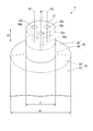
- the tube container 1 shown in FIGS. 1 and 2 includes a tube main body 10 and an extraction body 20 provided at the tip of the tube main body 10.
- the tube body 10 includes a cylindrical body 12 and a shoulder 14 formed at one end of the body 12, and an end (not shown) on the opposite side of the shoulder 14 is sealed. .
- the shoulder portion 14 is reduced in diameter toward the tip, and an extraction body 20 is provided at the tip.
- the pouring body 20 includes a flow path forming portion 22 and a cylindrical connecting tube portion 24 provided at the lower end, and the connecting tube portion 24 is connected to the shoulder portion 14.
- the tip surface 21 of the extraction body 20 is a flat surface.
- the flow path forming part 22 is formed by forming a first extraction flow path 30a, a second extraction flow path 30b, and a third extraction flow path 30c on a cylindrical member.
- the first extraction flow path 30 a extends from the tube body 10 side (connection cylinder portion 24 side) to the distal end of the extraction body 20 and opens at the distal end surface 21 of the extraction body 20. It communicates with the inside of the tube main body 10 via.
- the second extraction flow path 30b extends from the tube body 10 side (connection cylinder part 24 side) to the distal end of the extraction body 20, opens to the distal end surface 21 of the extraction body 20, and the inside of the connection cylinder part 24 It communicates with the inside of the tube main body 10 via.
- the third extraction flow path 30c extends from the tube body 10 side (connection cylinder portion 24 side) to the distal end of the extraction body 20, opens to the distal end surface 21 of the extraction body 20, and the inside of the connection cylinder portion 24 It communicates with the inside of the tube main body 10 via. That is, the first to third pouring channels communicate the inside and the outside of the tube body 10.
- drum 12 should just have flexibility, for example, the monolayer film which consists of resin, such as polyolefin, such as polypropylene or polyethylene, polyester, such as a polyethylene terephthalate, or polyamide, and these monolayer films A multilayer film in which is laminated.
- the multilayer film may include a metal thin film such as aluminum or a vapor deposition film. If the tube main body 10 is formed of such a single layer film or a multilayer film, the contents are poured out by pressing the body portion 12, and the shape of the body portion 12 is released by releasing the pressing of the body portion 12. In order to restore, the contents in the tube body 10 can be easily and repeatedly poured out.
- the width w1 of the tube body 10 is determined in consideration of the capacity of the tube container 1 and is set to 1 to 6 cm, for example.
- the width w ⁇ b> 1 is the width of the boundary portion between the body 12 and the shoulder 14 in the tube body 10, that is, the diameter of the shoulder 14.
- the length of the tube main body 10 can be determined in consideration of the capacity of the tube container 1 and is, for example, 3 to 20 cm.
- the thickness of the tube main body 10 is determined in consideration of the material of the tube main body 10 and is, for example, 100 to 700 ⁇ m. If it is less than the above lower limit value, the strength of the tube body 10 may be insufficient, and if it exceeds the upper limit value, the body part 12 may become too hard to easily pour out the contents.
- the shoulder 14 and the extraction body 20 are integrally formed by injection molding or the like.
- Examples of the material of the shoulder portion 14 and the extraction body 20 include a polyolefin such as polyethylene or polypropylene, or a resin such as polyester such as polyethylene terephthalate.
- the thickness of the shoulder 14 is determined in consideration of the rigidity required for the shoulder 14 and is, for example, 0.3 to 3 mm.
- the diameter r1 of the pouring body 20 is determined in consideration of the opening diameters of the first to third pouring channels, the width w1 of the tube body 10, and the like, for example, 5 to 50 mm.
- the inner diameter of the connecting cylinder portion 24 is determined in consideration of the physical properties of the contents, and is set to 3 to 45 mm, for example.
- the height h1 of the flow path forming portion 22 is determined in consideration of the physical properties of the contents, and is preferably 1 to 8 mm, for example, and more preferably 2 to 6 mm. If it is less than the said lower limit, it will become difficult to control the pouring direction of the content, the content will be poured out in various directions, and there exists a possibility that a handleability may not be made favorable. If it exceeds the above upper limit value, the handling property may not be further improved, and the pressure at the time of pouring out the contents becomes too high, which may make it difficult to pour out the contents.
- the first extraction flow path 30a has the same diameter from the tube main body 10 side (connection tube portion 24 side) to the distal end surface 21, and the first opening surface 32a of the first extraction flow path 30a in the distal end surface 21. Is a true circle in plan view.
- the axis P1 of the first extraction flow path 30a is perpendicular to the tip surface 21.
- the term “perpendicular” means that the minor angle formed between the axis P1 and the tip surface 21 is 87 to 90 °.
- the inferior angle formed by the axis P1 and the tip surface 21 is preferably more than 89.5 ° and not more than 90 °.
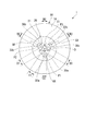
- the opening diameter R1 of the first pouring channel 30a is determined in consideration of the physical properties of the contents, and is, for example, preferably 0.3 to 6 mm, more preferably 1 to 5 mm, and further preferably 1 to 4 mm. If opening diameter R1 is less than the said lower limit, the pressure at the time of pouring out the contents will become too high, and there is a possibility that it will become difficult to pour out the contents. If the value exceeds the upper limit, the dispersibility of the dispensed contents may be reduced, or the dispensing direction of the contents may be difficult to control, and the handleability may be degraded.
- the distance from the periphery of the first opening surface 32a to the periphery of the second opening surface 32b, that is, the distance D1 between the first extraction channel 30a and the second extraction channel 30b is, for example, 0. 5 to 6 mm is preferable, and 1 to 5 mm is more preferable. If the distance D1 is less than the lower limit, the dispersibility of the dispensed contents may be reduced. If the distance D1 is greater than the above upper limit value, it becomes difficult to control the direction in which the contents are poured out, and the handleability may be reduced.
- the distance from the periphery of the first opening surface 32a to the periphery of the third opening surface 32c, that is, the distance D3 between the first extraction channel 30a and the third extraction channel 30c is the same as the distance D1. It is.
- the second extraction flow path 30b has the same diameter from the tube main body 10 side (connection tube portion 24 side) to the distal end surface 21, and the second opening surface 32b of the second extraction flow path 30b in the distal end surface 21. Is a true circle in plan view.
- the axis P2 of the second extraction flow path 30b is perpendicular to the tip surface 21.
- the minor angle formed between the axis P2 and the tip surface 21 is the same as the minor angle formed between the axis P1 and the tip surface 21.
- the opening diameter R2 of the second extraction channel 30b is the same as the opening diameter R1.
- the distance from the periphery of the second opening surface 32b to the periphery of the third opening surface 32c, that is, the distance D2 between the second extraction channel 30b and the third extraction channel 30c is the same as the distance D1. It is.
- the third extraction flow path 30c has the same diameter from the tube body 10 side (connecting cylinder portion 24 side) to the distal end surface 21, and the third opening surface 32c of the third extraction flow path 30c in the distal end surface 21. Is a true circle in plan view.
- the axis P3 of the third extraction flow path 30c is perpendicular to the tip surface 21.
- the minor angle formed between the axis P3 and the tip surface 21 is the same as the minor angle formed between the axis P1 and the tip surface 21.
- the opening diameter R3 of the third extraction channel 30c is the same as the opening diameter R1.
- the first to third extraction channels include an opening diameter R of the arbitrary extraction channel A and the other extraction channels closest to the extraction channel A and the extraction channel A.
- R1 / D1 is 0.1-5. It is preferably 0.3 to 3.
- R1 / D1 is less than the above lower limit value, the first opening surface 32a and the second opening surface 32b are too far apart from each other, so that the direction in which the contents are poured out cannot be controlled, and the handleability becomes insufficient. If R1 / D1 exceeds the above upper limit value, the first opening surface 32a and the second opening surface 32b are too close to each other, and the poured out contents become one lump, resulting in poor dispersibility of the contents. It will be enough.
- R1 / D3 is the same as R1 / D1.
- R2 / D1 is the same as R1 / D1.
- R2 / D2 is the same as R1 / D1.
- R3 / D2 is the same as R1 / D1.
- R3 / D3 is the same as R1 / D1.
- the opening diameters R1 to R3 may be the same or different from each other.
- the opening diameters R1 to R3 are preferably the same from the viewpoint that the contents can be uniformly dispensed from the first to third dispensing channels and the dispensing direction of the contents can be better controlled.
- the distances D1 to D3 may be the same or different from each other.
- the distances D1 to D3 are preferably the same from the viewpoint that the contents can be uniformly dispensed from the first to third dispensing channels and the dispensing direction of the contents can be better controlled.
- the axis P1, the axis P2, and the axis P3 are parallel to each other. Since the axes P1 to P3 are parallel to each other, the handling property when the contents are poured out is good, and the dispersibility of the poured out contents can be improved. “Parallel” means a relationship that can be visually recognized as parallel. For example, when the two axes are on the same plane, the minor angle formed by the two axes is 10 ° or less, preferably 3 ° or less, and more preferably 0.5 ° or less.
- the minor angle formed by the two axes when viewed so that the two axes intersect each other is preferably 10 ° or less, and preferably 3 ° or less, More preferably, it is 0.5 ° or less.
- the first opening surface 32 a, the second opening surface 32 b, and the third opening surface 32 c are annularly arranged around the center O of the tip surface 21. That is, the axis line P1, the axis line P2, and the axis line P3 are located in the virtual circle C1 with the center O as the center.
- the radius r2 of the virtual circle C1 is determined in consideration of the sizes of the first to third opening surfaces, and is preferably 2 to 5 mm, for example. When the radius r2 is less than the lower limit value, the contents poured out from the respective pouring channels tend to become one lump, and the dispersibility of the poured out contents may be lowered. When the radius r2 is more than the upper limit, it may be difficult to control the content dispensing direction.
- the angle ⁇ 1 formed by the line Q1 connecting the axis P1 and the center O and the line Q2 connecting the axis P2 and the center O is preferably 100 to 140 °, and more preferably 110 to 130 °.
- the angle ⁇ 2 formed by the line Q2 and the line Q3 connecting the axis P3 and the center O is preferably 100 to 140 °, and more preferably 110 to 130 °.
- the angle ⁇ 2 formed by the line Q1 and the line Q3 is preferably 100 to 140 °, more preferably 110 to 130 °.
- the angles ⁇ 1 to ⁇ 3 are preferably the same as each other.
- angles ⁇ 1 to ⁇ 3 are the same, the handleability when the contents are poured out is good, and the dispersibility of the poured out contents can be improved. That the angles ⁇ 1 to ⁇ 3 are the same means that the difference between any two angles selected from the angles ⁇ 1 to ⁇ 3 is within a range of ⁇ 10 ° to 10 °.
- the tube container 1 of the present embodiment is manufactured according to a conventionally known method for manufacturing a tube container.
- a member in which the shoulder portion 14 and the extraction body 20 are integrally formed (hereinafter referred to as “extraction member”) is obtained by injection molding or the like.
- a sheet-like base material is formed into a cylindrical shape to form a body portion 12, or a tubular base material obtained by inflation molding is used as a body portion 12, and an extraction member is heat-sealed to one end of the body portion 12. Or glue.
- a lid (not shown) to the extraction body 20
- the extraction body 20 is provided at the tip of the tube main body 10, and the tube container 1 having an open rear end is obtained.
- the lid is not particularly limited, and may be one that externally fits into the extraction body 20 or may be screwed into the extraction body 20.
- the content may be in the form of a paste, and examples thereof include oral compositions such as dentifrices, cosmetics, foods, and the like.
- the composition of the contents is not particularly limited as long as the later mentioned ⁇ / ⁇ ratio is 20 to 70.
- the composition of the oral composition is a combination of conventionally known materials such as cleaning agents, surfactants, binders, wetting agents, fragrances, pigments, pH adjusting agents, sweeteners, and other active ingredients. Is mentioned.
- silica-based abrasives such as silica gel, precipitated silica, aluminosilicate, zirconosilicate, calcium pyrophosphate, calcium carbonate, aluminum hydroxide, alumina, magnesium carbonate, tribasic magnesium phosphate, zeolite, zirconium silicate, Examples thereof include hydroxyapatite and synthetic resin abrasives.
- These cleaning agents may be used alone or in a combination of two or more.
- the content of the cleaning agent in the oral composition is not particularly limited, but is appropriately determined in the range of 0 to 60% by mass.
- the surfactant examples include an anionic surfactant, a cationic surfactant, a nonionic surfactant, and an amphoteric surfactant.
- Specific examples of the anionic surfactant include sodium lauryl sulfate, sodium myristyl sulfate, sodium N-lauroyl sarcosinate, sodium N-myristol sarcosine, sodium dodecylbenzene sulfonate, sodium hydrogenated coconut fatty acid monoglyceride monosulfate, Examples include sodium lauryl sulfoacetate, sodium ⁇ -olefin sulfonate, sodium N-palmitoyl glutamate, sodium N-methyl-N-acyl taurate, and sodium N-methyl-N-acylalanine.
- the cationic surfactant include distearylmethylammonium chloride or stearyldimethylbenzylammonium chloride.
- specific examples of the nonionic surfactant include sugar alcohol fatty acid esters such as sorbitan fatty acid ester, polyoxyethylene sorbitan fatty acid ester or sucrose fatty acid ester, glycerin fatty acid ester, polyglycerin fatty acid ester, polyoxyethylene glycerin fatty acid ester.
- an ether type activator such as polyhydric alcohol fatty acid ester such as polyethylene glycol fatty acid ester, polyoxyethylene alkyl ether, polyoxyethylene polyoxypropylene copolymer, polyoxyethylene alkylphenyl ether or polyoxyethylene hydrogenated castor oil, And fatty acid alkanolamides such as lauric acid diethanolamide.
- amphoteric surfactants include N-alkyldiaminoethylglycines such as 2-alkyl-N-carboxymethyl-N-hydroxyethylimidazolium betaine, N-lauryldiaminoethylglycine, N-myristyldiaminoethylglycine, etc.
- sodium N-alkyl-1-hydroxyethylimidazoline betaine and the like can be mentioned.
- These surfactants may be used singly or in combination of two or more.
- the content of the surfactant in the oral composition can be determined in consideration of the type of the surfactant, and is appropriately determined, for example, in the range of 0.1 to 10% by mass.
- binder examples include cellulosic binders, carrageenan, xanthan gum, guar gum, sodium alginate, montmorillonite, gelatin, sodium polyacrylate, agar, gellan gum or pectin.
- cellulose binder examples include carboxymethylcellulose, hydroxyethylcellulose, hydroxypropylcellulose, hydroxypropylmethylcellulose, hydroxymethylethylcellulose, methylcellulose, or cationized cellulose. These binders may be used individually by 1 type, and may be used in combination of 2 or more type.
- the content of the binder in the oral composition can be determined in consideration of the type of binder and the like, and is appropriately determined in the range of, for example, 0.1 to 5% by mass.
- the wetting agent examples include polyhydric alcohols.
- specific examples of the polyhydric alcohol include propylene glycol, pentylene glycol, hexylene glycol, octylene glycol, polyethylene glycol having a molecular weight of 200 to 6000, ethylene glycol, 1,3-butylene glycol, and reduced starch. Saccharified products, sorbit, glycerin, xylitol, erythritol and the like can be mentioned.
- These wetting agents may be used individually by 1 type, and may be used in combination of 2 or more type.
- the content of the humectant in the oral composition can be determined in consideration of the type of humectant and the like, and is appropriately determined in the range of, for example, 5 to 70% by mass.
- the thixotropic property and the viscosity have a predetermined relationship.
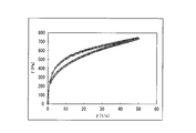
- the thixotropic property of the contents is evaluated by an area (hereinafter also referred to as a hysteresis area) ⁇ (Pa / s) surrounded by a hysteresis loop drawn when shear stress is measured with a cone plate viscometer.
- Hysteresis loop is shown by the relationship of shear stress to shear rate. Ascending curve drawn when shear rate is increased by an arbitrary value and descending curve drawn when shear rate is lowered by an arbitrary value. It consists of.
- the content having thixotropy has a rising curve and a falling curve that do not overlap, and the hysteresis area ⁇ is measured.
- the hysteresis area ⁇ is measured using a cone plate viscometer (Rheo Stress RS50, manufactured by HAAKE) under the following measurement conditions.
- the hysteresis area ⁇ is preferably 200 to 5000 Pa / s, and more preferably 500 to 3000 Pa / s.
- the hysteresis area ⁇ is adjusted by the type and content of the binder in the contents.
- the viscosity ⁇ of the content is not particularly limited, but is preferably 15 to 65 Pa ⁇ s, more preferably 20 to 60 Pa ⁇ s.
- the viscosity ⁇ is less than the above lower limit, the fluidity of the content is excessively increased, and it becomes difficult to control the direction in which the content is poured out, and the content ⁇ tends to sag from the applicator. If the value exceeds the upper limit, the fluidity of the content becomes too low, the dispersibility of the poured out content decreases, and the dispensing direction of the content becomes difficult to control.
- the viscosity ⁇ is a value measured with a BH type rotary viscometer (TVB-10, manufactured by Toki Sangyo Co., Ltd.) under the following conditions.
- the viscosity ⁇ is adjusted by the type and content of the binder in the contents.
- the hysteresis area ⁇ / viscosity ⁇ (hereinafter sometimes referred to as ⁇ / ⁇ ratio) in the contents is 20 to 70, preferably 25 to 50.
- ⁇ / ⁇ ratio is less than the above lower limit, the viscosity of the content is too high, making it difficult to increase the dispersibility of the content and making it difficult to pour the content.
- ⁇ / ⁇ ratio exceeds the above upper limit, the viscosity of the contents becomes too low, and when the contents are poured out, the contents are scattered, making it difficult to control the pouring direction and improving the handleability. Absent.
- the product in a tube container is manufactured according to a conventionally known method for manufacturing a product in a tube container. For example, after filling the tube main body 10 with the contents from the opened rear end, the rear end of the tube main body 10 is sealed to obtain a tube container 1 containing the contents (product containing the tube container).
- the usage method of the product in a tube container is demonstrated.
- the lid is removed from the dispensing body 20, the distal end surface 21 is brought close to an applicator (for example, a toothbrush), and the body portion 12 is pressed.
- an applicator for example, a toothbrush
- the contents circulate in the connecting cylinder portion 24 and the first to third extraction flow paths in order, and are discharged from the first to third opening surfaces.
- the contents are placed on the applicator in a shape in which a material having a thickness substantially equal to the opening diameter of the first to third extraction channels is partially in contact. Since the content placed on the applicator has a large surface area relative to the volume, for example, when cleaning the inside of the oral cavity, the content is quickly dispersed, and the effect expression can be accelerated.
- the first to third extraction channels are parallel to each other, so that the contents are extracted without spreading outward. For this reason, handling property becomes favorable.
- the R / D ratio of the first to third pouring channels is 0.1 to 5 and the ⁇ / ⁇ ratio of the contents is 20 to 70, the first to third openings The contents poured out from the surface are put on the applicator without becoming one lump. For this reason, the dispersibility of the contents increases.
- the tube-contained product of this embodiment is useful for oral compositions, cosmetics or foods in containers. Among them, it is particularly useful for a dentifrice product that is poured into a narrow place such as a flocked portion of a toothbrush and then rapidly dispersed in the oral cavity.
- the present invention is not limited to the embodiment described above.
- three pouring channels are formed in the pouring body, but the present invention is not limited to this, and the number of pouring channels may be two or four. It may be the above. However, from the viewpoint of improving the handleability and further improving the dispersibility of the contents, the number of the extraction channels is preferably 3 to 8, and more preferably 3 to 5.
- the axes of the first to third extraction channels are located in a virtual circle drawn from the center of the tip surface of the extraction body, that is, the centers of the tip surface and the extraction channel.
- the center of gravity of the figure whose apex is the center of the opening surface coincides.
- the present invention is not limited to this, and the center of the tip surface and the center of gravity of the figure whose apex is the center of the opening surface of the extraction channel may be shifted.
- the center of the tip surface and the center of gravity of the figure having the apex at the center of the opening surface of the pouring channel are: It is preferable that they match.
- the first to third opening surfaces are arranged on the ring, but the present invention is not limited to this, and the first to third opening surfaces may be arranged on a straight line. Moreover, when four or more extraction flow paths are formed, one opening surface may be formed in the center of a front end surface, and the other opening surface may be arrange
- the first to third extraction flow paths have the same diameter from the tube main body side to the distal end surface.
- the present invention is not limited to this, and the tube main body side to the distal end surface is not limited thereto.
- the diameter may be gradually reduced toward the opposite side, or the diameter may be gradually increased from the tube main body side toward the distal end surface.
- the dispensing flow path may have the same diameter from the tube body side to the distal end surface, or may be gradually reduced in diameter from the tube body side to the distal end surface. preferable.
- the first to third opening surfaces are perfectly circular in a plan view.
- the present invention is not limited to this, and the first to third opening surfaces are in a plan view such as a triangle or a quadrangle.
- a polygon may be sufficient and a planar view ellipse may be sufficient.
- the opening diameter is a diameter of a circle circumscribing the opening surface.
- the extraction channel closest to the first extraction channel is the second extraction channel
- the shoulder portion is formed on the tube body, but the present invention is not limited to this.
- the shoulder portion is not formed on the tube body, and the same diameter as the inner diameter of the front end of the trunk portion is used.
- the protruding body may be provided at the front end of the trunk.
- the pouring body and the shoulder portion are integrally formed.
- the present invention is not limited to this, and the pouring body and the shoulder portion may be respectively formed and provided on the trunk portion.
- the body portion and the shoulder portion may be integrally formed, and an extraction body may be provided on this.
- the tip surface of the extraction body is a flat surface, but the present invention is not limited to this, and the tip surface may be a convex surface or a concave surface.
- the flow path forming portion is a columnar member formed with the pouring flow path, but the present invention is not limited to this, and the flow path forming portion is a polygonal columnar member.
- a pour-out channel may be formed.
- the connection cylinder part is provided in the lower end of the flow-path formation part, this invention is not limited to this, The connection cylinder part does not need to be provided.
- the connecting tube portion is cylindrical, but the connecting tube portion may be determined according to the shape of the flow path forming portion, and may be, for example, a polygonal tube shape.
- the body portion is cylindrical.
- the present invention is not limited to this, and the body portion may be a polygonal cylinder, and the cross section is a flat shape such as an ellipse. Also good.
- Examples 1 to 4 Comparative Examples 1 and 2
- a tube-contained product in which the oral composition was contained in a tube container similar to the tube container 1 shown in FIGS. 1 and 2 was obtained.
- a pouring member in which the pouring body having the specifications shown in Tables 2 and 5 and the shoulder are integrated by injection molding (diameter r1: 14 mm of the pouring body, height h1: 2 mm of the flow path forming portion, (Made of polypropylene).
- the pouring bodies have the same opening diameters R1 to R3 and the same distances D1 to D3 in FIG.
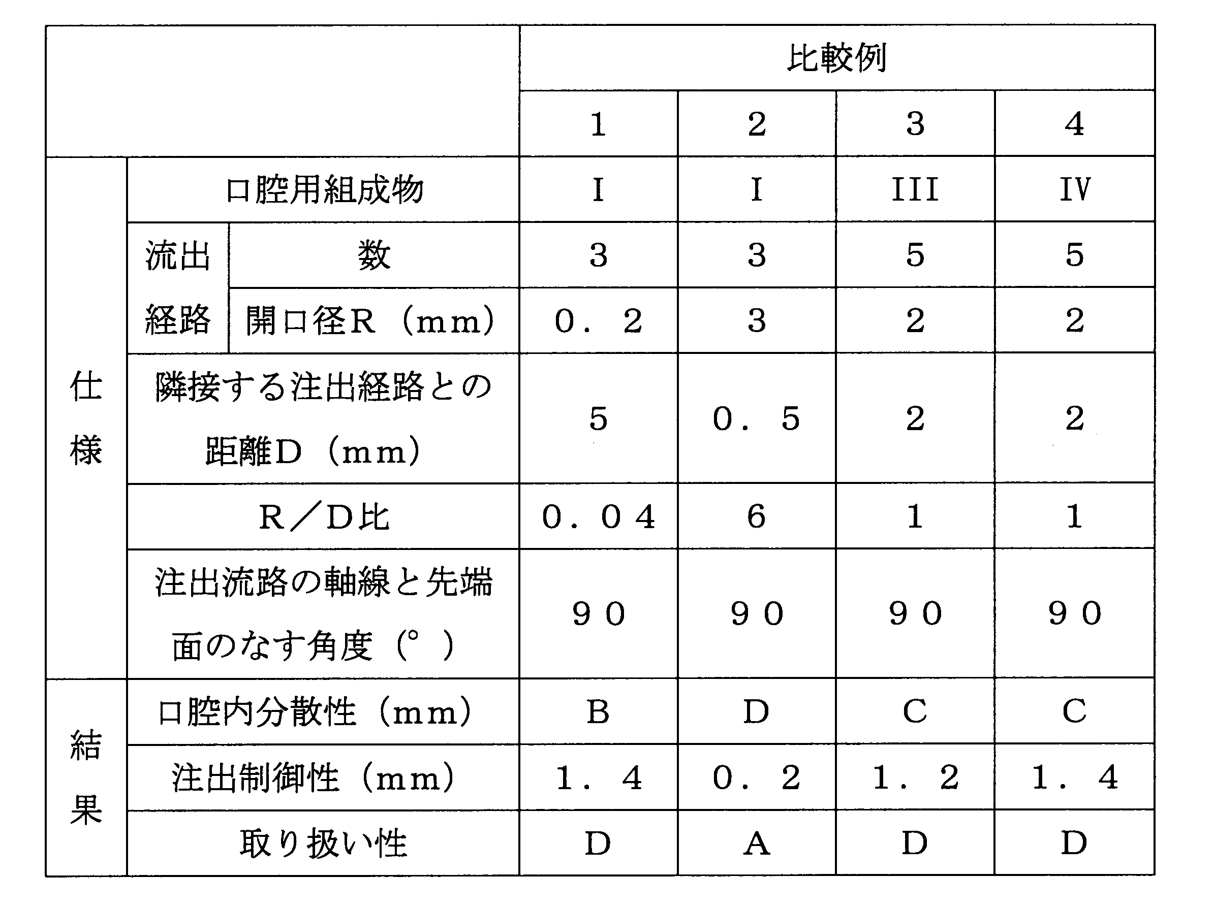
- Examples 5 to 11, Comparative Examples 3 to 4 According to the specifications shown in Tables 3 to 5, a tube-contained product was obtained in the same manner as in Example 1 except that five pouring channels were arranged in an annular shape. The obtained product in a tube container was evaluated for dispersibility in the oral cavity, dispensing controllability and handleability, and the results are shown in Tables 3-5.
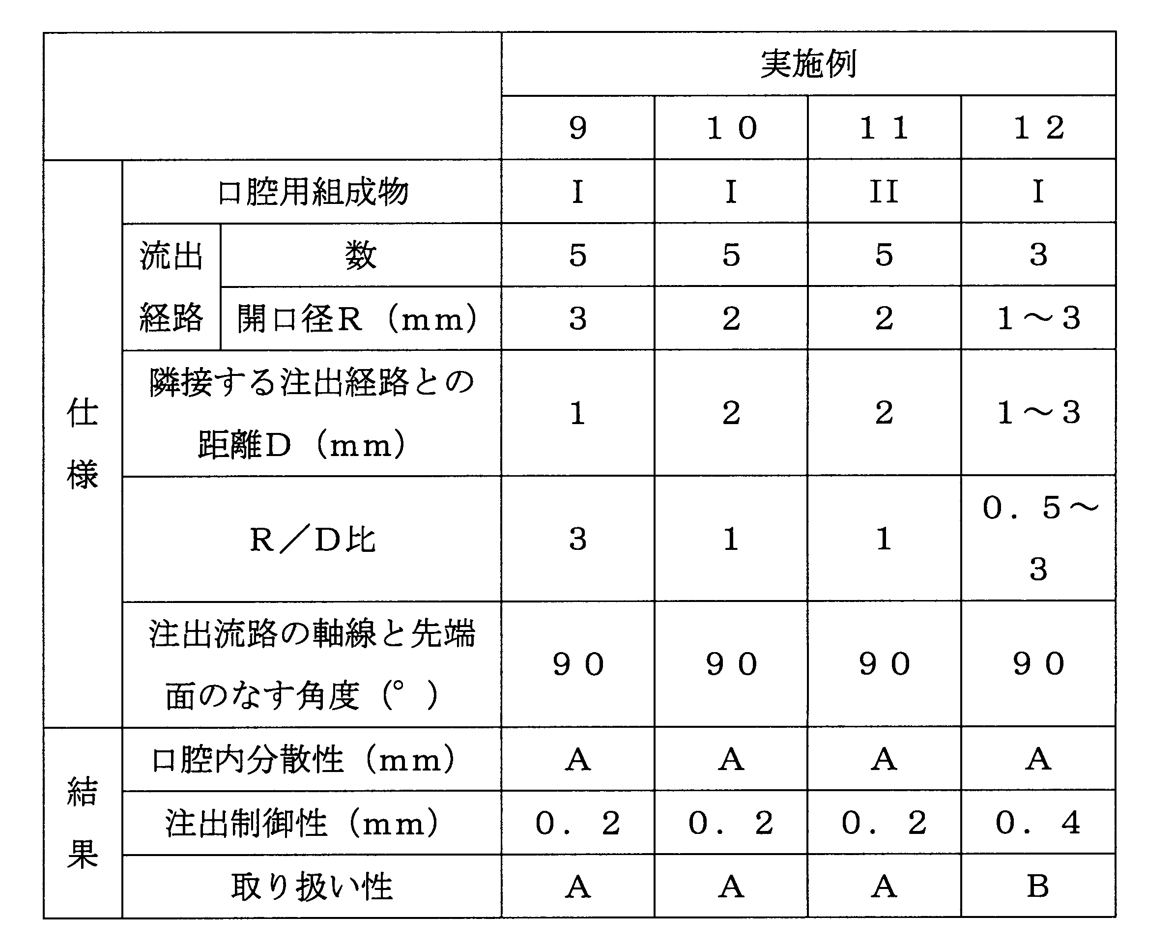
- Example 12 A tube container product is obtained in the same manner as in Example 1 except that the opening diameter R1 is 1 mm, the opening diameter R2 is 2 mm, the opening diameter R3 is 3 mm, the distance D1 is 2 mm, the distance D2 is 1 mm, and the distance D3 is 3 mm. It was.
- the R / D ratio (R1 / D1) in the first extraction channel is 0.5
- the R / D ratio (R2 / D2) in the second extraction channel is 2
- the third The R / D ratio (R3 / D2) in the extraction channel is 3.
- Table 4 About the obtained tube container containing product, oral dispersibility, extraction controllability, and handleability were evaluated, and the results are shown in Table 4.
- A An average score of 3.5 points or more.
- B The average score is 3.0 or more and less than 3.5.
- C The average score is 2.0 or more and less than 3.0.
- D The average score is less than 2.0 points.
- A An average score of 3.5 points or more.
- B The average score is 3.0 or more and less than 3.5.
- C The average score is 2.0 or more and less than 3.0.
- D The average score is less than 2.0 points.
- the intraoral dispersibility is “B” or “A”
- the dispensing controllability is 0.6 mm or less
- the handleability is “B”.
- A the number of extraction channels in Examples 2 to 3
- the number of extraction channels is three and the R / D ratio is 0.1.
- the handleability was good.
- the dispersibility in the oral cavity was better than that in Example 4 having three dispensing channels and an R / D ratio of 5.
- the handleability was “D”.
- Comparative Example 3 using an oral composition having an ⁇ / ⁇ ratio of less than 20 and Comparative Example 4 using an oral composition having an ⁇ / ⁇ ratio exceeding 70 have an oral dispersibility of “C”, The handleability was “D”. From these results, it was found that by applying the present invention, the handleability of the product in the tube container can be improved and the dispersibility of the contents can be improved.
- Tube container 10 Tube main body 20 Extraction body 21 Tip surface 30a 1st extraction flow path 30b 2nd extraction flow path 30c 3rd extraction flow path 32a 1st opening surface 32b 2nd opening surface 32c Third opening surface R1, R2, R3 Aperture diameter D1, D2, D3 Distance P1, P2, P3 Axis
Landscapes
- Engineering & Computer Science (AREA)
- Mechanical Engineering (AREA)
- Tubes (AREA)
- Cosmetics (AREA)
Description
本願は、2012年7月6日に、日本に出願された特願2012-152885号に基づき優先権を主張し、その内容をここに援用する。
ペースト状製剤で対象部位を処理する際には、手の平や歯ブラシ等のアプリケーターにチューブ容器からペースト状製剤を注出し、これを対象部位に塗布したり、アプリケーターで対象部位を擦掃(brushing)したりする。
また、特許文献2の技術では、内容物の分散性を高められるものの、内容物の物性によっては、内容物が様々な方向に注出され、取り扱い性に劣る。
そこで、本発明は、取り扱い性が良好で、内容物の分散性を高められるチューブ容器入り製品を目的とする。
本実施形態のチューブ容器入り製品は、チューブ容器にペースト状の内容物が収容されたものである。
第二の注出流路30bは、チューブ本体10側(接続筒部24側)から注出体20の先端に延びて注出体20の先端面21に開口し、かつ接続筒部24の内部を介してチューブ本体10内と連通するものである。
第三の注出流路30cは、チューブ本体10側(接続筒部24側)から注出体20の先端に延びて注出体20の先端面21に開口し、かつ接続筒部24の内部を介してチューブ本体10内と連通するものである。
即ち、第一~第三の注出流路は、チューブ本体10の内部と外部とを連通するものである。
チューブ本体10の長さは、チューブ容器1の容量等を勘案して決定でき、例えば、3~20cmとされる。
第一の注出流路30aの軸線P1は、先端面21に垂直である。垂直とは、軸線P1と先端面21とのなす劣角が87~90°であることをいう。軸線P1と先端面21とのなす劣角は、89.5°超90°以下が好ましい。
第一の注出流路30aの開口径R1は、内容物の物性等を勘案して決定され、例えば、0.3~6mmが好ましく、1~5mmがより好ましく、1~4mmがさらに好ましい。開口径R1が上記下限値未満では、内容物を注出する際の圧力が高くなりすぎて、内容物を注出しにくくなるおそれがある。上記上限値超では、注出された内容物の分散性が低下したり、内容物の注出方向を制御しにくくなって、取り扱い性が低下するおそれがある。
第一の開口面32aの周縁から第三の開口面32cの周縁までの距離、即ち、第一の注出流路30aと第三の注出流路30cとの距離D3は、距離D1と同様である。
第二の注出流路30bの軸線P2は、先端面21に垂直である。軸線P2と先端面21とのなす劣角は、軸線P1と先端面21とがなす劣角と同様である。
第二の注出流路30bの開口径R2は、開口径R1と同様である。
第二の開口面32bの周縁から第三の開口面32cの周縁までの距離、即ち、第二の注出流路30bと第三の注出流路30cとの距離D2は、距離D1と同様である。
第三の注出流路30cの軸線P3は、先端面21に垂直である。軸線P3と先端面21とのなす劣角は、軸線P1と先端面21とのなす劣角と同様である。
第三の注出流路30cの開口径R3は、開口径R1と同様である。
本実施形態において、第一の注出流路30aが注出流路Aであり、第二の注出流路30bが注出流路Bである場合、R1/D1は、0.1~5であり、0.3~3であることが好ましい。R1/D1が上記下限値未満では、第一の開口面32aと第二の開口面32bとが離れすぎて、内容物の注出方向を制御できず、取り扱い性が不十分になる。R1/D1が上記上限値超では、第一の開口面32aと第二の開口面32bとが近づきすぎて、注出された内容物が1つの塊となって、内容物の分散性が不十分になる。
第一の注出流路30aが注出流路Aであり、第三の注出流路30cが注出流路Bである場合、R1/D3は、R1/D1と同様である。
第二の注出流路30bが注出流路Aであり、第一の注出流路30aが注出流路Bである場合、R2/D1は、R1/D1と同様である。
第二の注出流路30bが注出流路Aであり、第三の注出流路30cが注出流路Bである場合、R2/D2は、R1/D1と同様である。
第三の注出流路30cが注出流路Aであり、第二の注出流路30bが注出流路Bである場合、R3/D2は、R1/D1と同様である。
第三の注出流路30cが注出流路Aであり、第一の注出流路30aが注出流路Bである場合、R3/D3は、R1/D1と同様である。
なお、本実施形態においては、第一~第三の注出流路は、互いにR/D=0.1~5となるように形成されている。
平行であるとは、目視で平行と認識できる関係を意味する。例えば、2つの軸線が同一平面上にある場合には、2つの軸線のなす劣角が10°以下であり、3°以下であることが好ましく、0.5°以下であることがより好ましい。あるいは、2つの軸線がねじれの位置にある場合には、2つの軸線が交差するように見た時に、2つの軸線のなす劣角が10°以下であり、3°以下であることが好ましく、0.5°以下であることがより好ましい。
仮想円C1の半径r2は、第一~第三の開口面の大きさを勘案して決定され、例えば、2~5mmが好ましい。半径r2が上記下限値未満である場合は、各々の注出流路から注出された内容物同士が1つの塊になりやすく、注出された内容物の分散性が低くなるおそれがある。半径r2が上記上限値超である場合は、内容物の注出方向を制御しにくくなるおそれがある。
線Q2と、軸線P3と中心Oとを結ぶ線Q3とのなす角度θ2は、100~140°が好ましく、110~130°がより好ましい。
線Q1と、線Q3とのなす角度θ2は、100~140°が好ましく、110~130°がより好ましい。
角度θ1~θ3は、互いに同じであることが好ましい。角度θ1~θ3が同じであれば、内容物を注出する際の取り扱い性が良好で、かつ注出された内容物の分散性を高められる。角度θ1~θ3が互いに同じであるとは、角度θ1~θ3から選択される任意の2つの角度の差が、-10°~10°の範囲内であることを意味する。
口腔用組成物中の清掃剤の含有量は、特に限定されないが、0~60質量%の範囲で適宜決定される。
口腔用組成物中の界面活性剤の含有量は、界面活性剤の種類を勘案して決定でき、例えば、0.1~10質量%の範囲で適宜決定される。
口腔用組成物中の粘結剤の含有量は、粘結剤の種類等を勘案して決定でき、例えば、0.1~5質量%の範囲で適宜決定される。
口腔用組成物中の湿潤剤の含有量は、湿潤剤の種類等を勘案して決定でき、例えば、5~70質量%の範囲で適宜決定される。
内容物のチキソトロピー性は、コーンプレート型粘度計でずり応力を測定した際に描かれるヒステリシスループで囲まれた面積(以下、ヒステリシス面積ということがある)α(Pa/s)で評価される。ヒステリシスループは、ずり速度に対するずり応力の関係で示されるものであり、ずり速度を任意の値で高めた際に描かれる上昇カーブと、ずり速度を任意の値で低めた際に描かれる下降カーブとからなる。チキソトロピー性を有する内容物は、上昇カーブと下降カーブとが重なり合わず、ヒステリシス面積αが測定される。
本明細書において、ヒステリシス面積αは、コーンプレート型粘度計(Rheo Stress RS50、HAAKE社製)を用い、下記測定条件で測定されたものである。
センサーC35/4度(コーンプレート型センサー35φ、角度4度)。
ずり速度γ=0~50(1/s)。
測定時間:120s。
測定温度:25°。
ヒステリシス面積αは、内容物中の粘結剤の種類や含有量により調節される。
本明細書において、粘度βは、BH型回転式粘度計(TVB-10、東機産業株式会社製)により、下記条件で測定された値である。
粘度βは、内容物中の粘結剤の種類や含有量により調節される。
ローター:No.7。
回転数:20rpm。
測定温度:25℃。
数値の読み取り:ローター回転開始から180秒後。
注出体20から蓋体を外し、先端面21をアプリケーター(例えば、歯ブラシ)に近接させ、胴部12を押圧する。胴部12を押圧すると、内容物が接続筒部24内と第一~第三の注出流路とを順に流通し、第一~第三の開口面から注出される。そして、内容物は、第一~第三の注出流路の開口径と略同等の太さのものが部分的に接触した形状となって、アプリケーター上に載せられる。アプリケーター上に載せられた内容物は、体積に対する表面積が大きいため、例えば、口腔内を清掃する際には、内容物が速やかに分散し、効果発現を速められる。
加えて、第一~第三の注出流路のR/D比が0.1~5であり、かつ内容物のα/β比が20~70であるため、第一~第三の開口面から注出された内容物は、1つの塊になることなく、アプリケーター上に載せられる。このため、内容物の分散性が高まる。
上述の実施形態では、流路形成部の下端に接続筒部が設けられているが、本発明はこれに限定されず、接続筒部が設けられていなくてもよい。
上述の実施形態では、接続筒部が円筒状とされているが、接続筒部は、流路形成部の形状に応じて決定されればよく、例えば、多角筒状であってもよい。
表1に示す組成に従い、各成分をスリーワンモーターで混合して、口腔用組成物を内容物として得た。各口腔用組成物について、ずり応力を測定し、その結果からヒステリシス面積αを求めた。各口腔用組成物のずり応力の測定結果を図3~6に示す。図3~6は、縦軸にずり応力τ(Pa)、横軸にずり速度γ(1/s)を取ったグラフである。図3は口腔用組成物Iの測定結果、図4は口腔用組成物IIの測定結果、図5は口腔用組成物IIIの測定結果、図6は口腔用組成物IVの測定結果である。
別途、各口腔用組成物について、粘度βを測定した。ヒステリシス面積αと粘度βの測定結果を表1に示す。

以下の手順によって、図1~2に示すチューブ容器1と同様のチューブ容器に、口腔用組成物が収容されたチューブ容器入り製品を得た。
射出成形によって、表2及び表5に示す仕様の注出体と、肩部とが一体となった注出部材(注出体の直径r1:14mm、流路形成部の高さh1:2mm、ポリプロピレン製)を成形した。この注出体は、図2における開口径R1~R3が同じであり、距離D1~D3が同じものである。
直径38mmの円筒状のラミネートチューブ(低密度ポリエチレン72μm/エチレン・アクリル酸共重合体樹脂90μm/アルミニウム10μm/エチレン・アクリル酸共重合体樹脂35μm/直鎖状低密度ポリエチレン50μm、厚み257μm、大日本印刷株式会社製)で胴部を形成し、この胴部の一方の開口端に注出部材を溶着させた。表2及び表5に従い、胴部の他方の開口端から、表2及び表5に示す口腔用組成物100gを充填し、前記の他方の開口端を封止して、各例のチューブ容器入り製品を得た。
得られたチューブ容器入り製品について、口腔内分散性、注出制御性及び取り扱い性について評価し、その結果を表2及び表5に示す。
表3~5に示す仕様に従い、5つの注出流路を環状に配置した以外は、実施例1と同様にしてチューブ容器入り製品を得た。得られたチューブ容器入り製品について、口腔内分散性、注出制御性及び取り扱い性について評価し、その結果を表3~5に示す。
開口径R1を1mm、開口径R2を2mm、開口径R3を3mm、距離D1を2mm、距離D2を1mm、距離D3を3mmとした以外は、実施例1と同様にしてチューブ容器入り製品を得た。このチューブ容器において、第一の注出流路におけるR/D比(R1/D1)は0.5、第二の注出流路におけるR/D比(R2/D2)は2、第三の注出流路におけるR/D比(R3/D2)は3である。
得られたチューブ容器入り製品について、口腔内分散性、注出制御性及び取り扱い性について評価し、その結果を表4に示す。
<口腔内分散性>
10名のモニタが、各例のチューブ容器入り製品から口腔用組成物を歯ブラシに注出し、口腔内を清掃した際の感触を下記評価基準により評価した。10人の評価点の平均を下記判定基準に分類した。
4点:口腔内で口腔用組成物が分散する感触を非常に感じる。
3点:口腔内で口腔用組成物が分散する感触を感じる。
2点:口腔内で口腔用組成物が分散する感触をやや感じる。
1点:口腔内で口腔用組成物が分散する感触を感じない。
A:平均点3.5点以上。
B:平均点3.0点以上3.5点未満。
C:平均点2.0点以上3.0点未満。
D:平均点2.0点未満。
紙に2本の平行な線(離間距離:1cm)を描いて、これを測定用紙とした。各例のチューブ容器入り製品から、測定用紙に描かれた2本の平行な線の間に、前記の平行な線に沿って口腔用組成物を2cmの長さで注出した。その際、前記の平行な線から口腔用組成物がはみ出していれば、はみ出した口腔用組成物と、これと近接する線までの距離(はみ出し距離)を測定した。前記の平行な線から口腔用組成物がはみ出していない場合には、はみ出し距離を0mmとした。この操作を3回繰り返し、その平均値を求めた。はみ出し距離の平均値が0に近づくほど、注出方向が良好に制御されていると判断できる。
10名のモニタが、各例のチューブ容器入り製品から口腔用組成物を歯ブラシに注出した際の感触を下記評価基準により評価した。10人の評価点の平均を下記判定基準に分類した。
4点:口腔用組成物を歯ブラシに非常に載せやすい。
3点:口腔用組成物を歯ブラシに載せやすい。
2点:口腔用組成物を歯ブラシにやや載せやすい。
1点:口腔用組成物を歯ブラシに載せにくい。
A:平均点3.5点以上。
B:平均点3.0点以上3.5点未満。
C:平均点2.0点以上3.0点未満。
D:平均点2.0点未満。
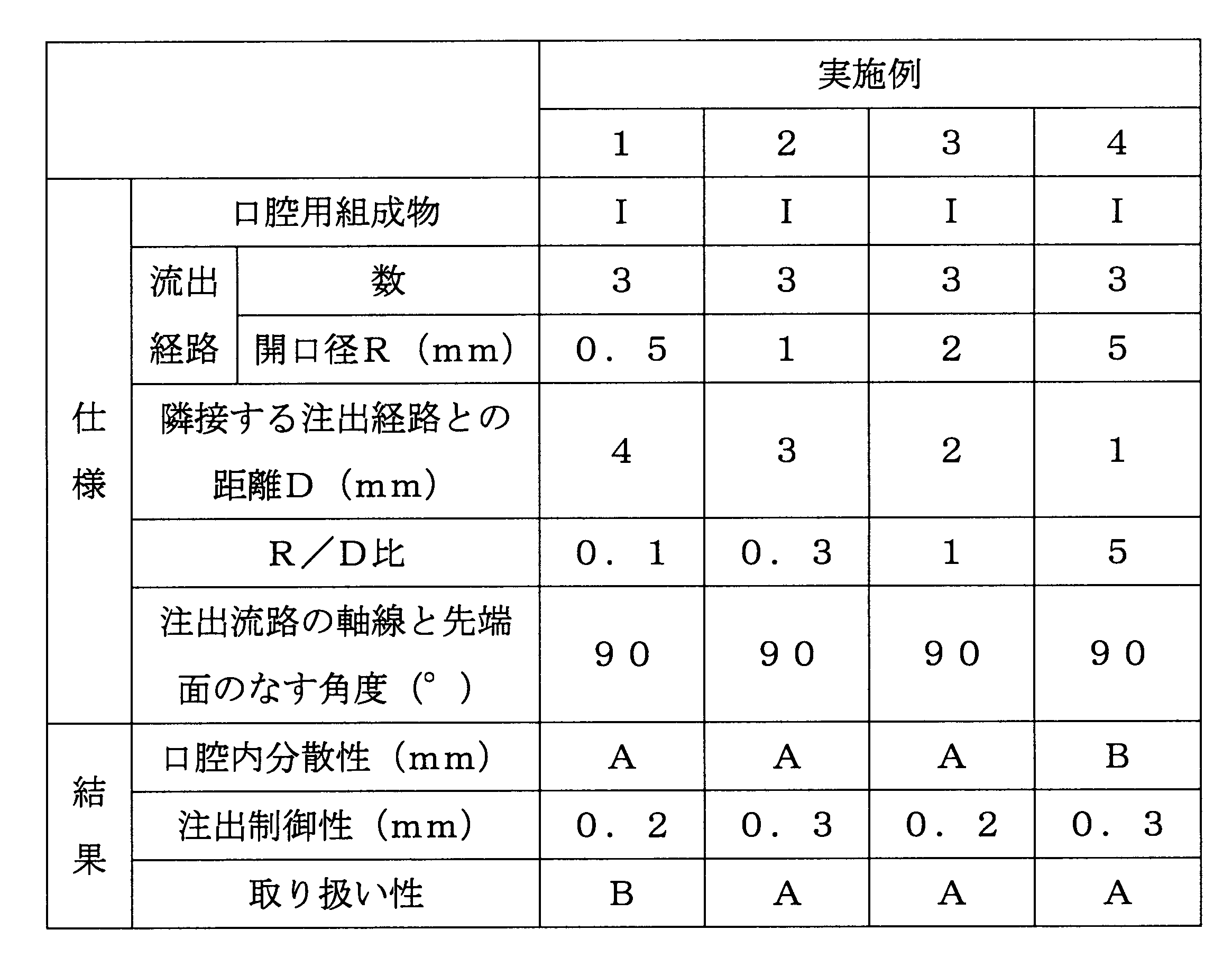
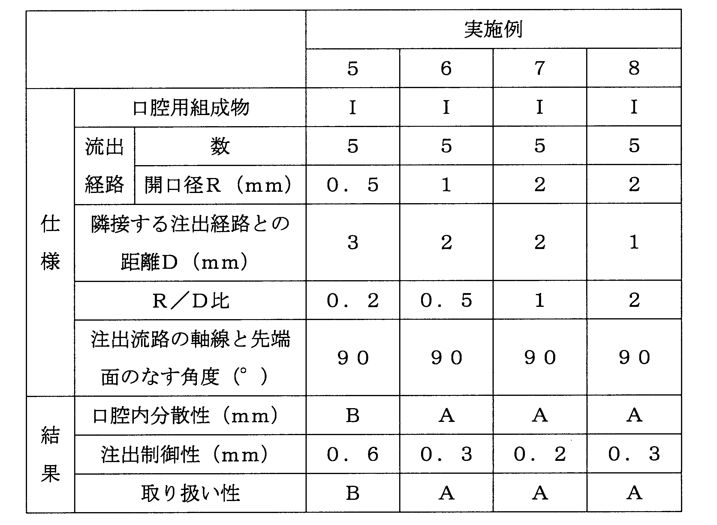
実施例2~3は、注出流路が3つで、R/D比が5である実施例4に比べて、口腔内分散性が良好なものであった。
R/D比が0.04である比較例1は、取り扱い性が「D」であった。α/β比が20未満である口腔用組成物を用いた比較例3、α/β比が70超である口腔用組成物を用いた比較例4は、口腔内分散性が「C」、取り扱い性が「D」であった。
これらの結果から、本発明を適用することで、チューブ容器入り製品の取り扱い性を良好にでき、かつ内容物の分散性を高められることが判った。
10 チューブ本体
20 注出体
21 先端面
30a 第一の注出流路
30b 第二の注出流路
30c 第三の注出流路
32a 第一の開口面
32b 第二の開口面
32c 第三の開口面
R1、R2、R3 開口径
D1、D2、D3 距離
P1、P2、P3 軸線
Claims (1)
- チューブ本体及び該チューブ本体の先端に設けられた注出体を備えるチューブ容器に、ペースト状の内容物が収容されてなるチューブ容器入り製品であって、
前記注出体には、先端に向かって延び、前記チューブ本体の内部と外部とを連通する2つ以上の注出流路が形成され、
前記注出流路の軸線は、互いに平行であり、
任意の前記注出流路Aの開口径Rと、前記注出流路Aと前記注出流路Aに最も近接する他の前記注出流路Bとの距離Dとの関係は、R/D=0.1~5を満たし、
前記内容物は、[コーンプレート型粘度計でずり応力を測定した際に描かれるヒステリシスループで囲まれた面積α(Pa/s)]/[回転式粘度計で測定された粘度β(Pa・s)]=20~70を満たすチューブ容器入り製品。
Priority Applications (2)
| Application Number | Priority Date | Filing Date | Title |
|---|---|---|---|
| JP2014523803A JP6192232B2 (ja) | 2012-07-06 | 2013-07-05 | チューブ容器入り口腔用製品 |
| CN201380027865.0A CN104349986B (zh) | 2012-07-06 | 2013-07-05 | 口腔用产品 |
Applications Claiming Priority (2)
| Application Number | Priority Date | Filing Date | Title |
|---|---|---|---|
| JP2012-152885 | 2012-07-06 | ||
| JP2012152885 | 2012-07-06 |
Publications (1)
| Publication Number | Publication Date |
|---|---|
| WO2014007365A1 true WO2014007365A1 (ja) | 2014-01-09 |
Family
ID=49882116
Family Applications (1)
| Application Number | Title | Priority Date | Filing Date |
|---|---|---|---|
| PCT/JP2013/068496 Ceased WO2014007365A1 (ja) | 2012-07-06 | 2013-07-05 | チューブ容器入り製品 |
Country Status (3)
| Country | Link |
|---|---|
| JP (1) | JP6192232B2 (ja) |
| CN (1) | CN104349986B (ja) |
| WO (1) | WO2014007365A1 (ja) |
Citations (2)
| Publication number | Priority date | Publication date | Assignee | Title |
|---|---|---|---|---|
| JPH08175942A (ja) * | 1994-12-26 | 1996-07-09 | Lion Corp | 歯磨組成物及びその評価方法 |
| JPH08310551A (ja) * | 1995-05-17 | 1996-11-26 | Kao Corp | スクイズ容器 |
Family Cites Families (4)
| Publication number | Priority date | Publication date | Assignee | Title |
|---|---|---|---|---|
| FR1353658A (fr) * | 1963-01-19 | 1964-02-28 | Bouchon amovible pour tube de pommade | |
| JP3535265B2 (ja) * | 1995-06-15 | 2004-06-07 | 株式会社コーセー | チューブ容器 |
| JP2003261154A (ja) * | 2002-03-06 | 2003-09-16 | Tadashi Saito | そば状排出口付きチューブ |
| JP2007253953A (ja) * | 2006-03-20 | 2007-10-04 | Sunstar Inc | ノズル構造及び該ノズル構造を備えた容器 |
-
2013
- 2013-07-05 CN CN201380027865.0A patent/CN104349986B/zh not_active Expired - Fee Related
- 2013-07-05 WO PCT/JP2013/068496 patent/WO2014007365A1/ja not_active Ceased
- 2013-07-05 JP JP2014523803A patent/JP6192232B2/ja active Active
Patent Citations (2)
| Publication number | Priority date | Publication date | Assignee | Title |
|---|---|---|---|---|
| JPH08175942A (ja) * | 1994-12-26 | 1996-07-09 | Lion Corp | 歯磨組成物及びその評価方法 |
| JPH08310551A (ja) * | 1995-05-17 | 1996-11-26 | Kao Corp | スクイズ容器 |
Also Published As
| Publication number | Publication date |
|---|---|
| CN104349986B (zh) | 2017-05-17 |
| JP6192232B2 (ja) | 2017-09-06 |
| JPWO2014007365A1 (ja) | 2016-06-02 |
| CN104349986A (zh) | 2015-02-11 |
Similar Documents
| Publication | Publication Date | Title |
|---|---|---|
| CN1266004C (zh) | 多室均匀配送管 | |
| US20030106905A1 (en) | Uniform dispensing, multi-chambered tube comprising a flow regulating element | |
| JP5339650B2 (ja) | 物質を基質上に送達するバイアル | |
| US8398324B2 (en) | Vial for delivering contents onto a substrate | |
| JP2012532809A (ja) | より広い先端部分を有するディップチューブを備えたポンプディスペンサー | |
| CN106458426A (zh) | 胶囊分配容器 | |
| BR112019018260A2 (pt) | Sistemas e métodos para criar superfícies lubrificáveis duráveis através da modificação interfacial | |
| HU223420B1 (hu) | Eljárás fizikailag elkülönített fogápoló készítmények együttes adagolására állandó arányban | |
| JP2017522163A (ja) | 塗布チップ付きチューブ | |
| JP6192232B2 (ja) | チューブ容器入り口腔用製品 | |
| JP5852910B2 (ja) | 容器入り口腔内用製剤 | |
| US20100035202A1 (en) | Systems and kits for promoting and maintaining oral health | |
| JP5871634B2 (ja) | チューブ容器及びチューブ容器入り製品 | |
| CN108136229A (zh) | 软包装的化妆品制剂 | |
| US20170135782A1 (en) | Clinical dispenser and applicator | |
| JP6275495B2 (ja) | 水不溶性粒子含有化粧料 | |
| JP2002511823A (ja) | 可撓性ポーチおよび分配ノズルアセンブリ | |
| JP5797420B2 (ja) | 清掃具 | |
| JP2006069946A (ja) | 微量定量噴霧用の水性懸濁剤 | |
| EP3518867B1 (en) | Tooth whitening kit | |
| WO2000013981A1 (en) | Shoulder design for tube | |
| JP2003230426A (ja) | 櫛付き容器 | |
| SE454945B (sv) | Agglomererade partiklar av ett dentalt polermedel avsedda att inforlivas i tandkrem | |
| JP2015074456A (ja) | チューブ容器 | |
| JP2000255600A (ja) | チューブ容器 |
Legal Events
| Date | Code | Title | Description |
|---|---|---|---|
| 121 | Ep: the epo has been informed by wipo that ep was designated in this application |
Ref document number: 13813992 Country of ref document: EP Kind code of ref document: A1 |
|
| ENP | Entry into the national phase |
Ref document number: 2014523803 Country of ref document: JP Kind code of ref document: A |
|
| NENP | Non-entry into the national phase |
Ref country code: DE |
|
| WWE | Wipo information: entry into national phase |
Ref document number: IDP00201500682 Country of ref document: ID |
|
| 122 | Ep: pct application non-entry in european phase |
Ref document number: 13813992 Country of ref document: EP Kind code of ref document: A1 |