WO2014007191A1 - 細胞展開用マイクロチャンバーチップの製造方法 - Google Patents
細胞展開用マイクロチャンバーチップの製造方法 Download PDFInfo
- Publication number
- WO2014007191A1 WO2014007191A1 PCT/JP2013/067979 JP2013067979W WO2014007191A1 WO 2014007191 A1 WO2014007191 A1 WO 2014007191A1 JP 2013067979 W JP2013067979 W JP 2013067979W WO 2014007191 A1 WO2014007191 A1 WO 2014007191A1
- Authority
- WO
- WIPO (PCT)
- Prior art keywords
- microchamber
- blocking
- cells
- chip
- substrate
- Prior art date
- Legal status (The legal status is an assumption and is not a legal conclusion. Google has not performed a legal analysis and makes no representation as to the accuracy of the status listed.)
- Ceased
Links
Images




Classifications
-
- C—CHEMISTRY; METALLURGY
- C12—BIOCHEMISTRY; BEER; SPIRITS; WINE; VINEGAR; MICROBIOLOGY; ENZYMOLOGY; MUTATION OR GENETIC ENGINEERING
- C12M—APPARATUS FOR ENZYMOLOGY OR MICROBIOLOGY; APPARATUS FOR CULTURING MICROORGANISMS FOR PRODUCING BIOMASS, FOR GROWING CELLS OR FOR OBTAINING FERMENTATION OR METABOLIC PRODUCTS, i.e. BIOREACTORS OR FERMENTERS
- C12M25/00—Means for supporting, enclosing or fixing the microorganisms, e.g. immunocoatings
-
- C—CHEMISTRY; METALLURGY
- C12—BIOCHEMISTRY; BEER; SPIRITS; WINE; VINEGAR; MICROBIOLOGY; ENZYMOLOGY; MUTATION OR GENETIC ENGINEERING
- C12M—APPARATUS FOR ENZYMOLOGY OR MICROBIOLOGY; APPARATUS FOR CULTURING MICROORGANISMS FOR PRODUCING BIOMASS, FOR GROWING CELLS OR FOR OBTAINING FERMENTATION OR METABOLIC PRODUCTS, i.e. BIOREACTORS OR FERMENTERS
- C12M33/00—Means for introduction, transport, positioning, extraction, harvesting, peeling or sampling of biological material in or from the apparatus
Definitions
- the present invention relates to a method for producing a microchamber chip for cell development in which at least the bottom surface of the microchamber is not subjected to blocking treatment.
- Circulating tumor cells [CTC], vascular endothelial cells, vascular endothelial progenitor cells, various stem cells, etc. (collectively referred to herein as “rare cells”) are cells that are very rarely present in whole blood depending on the disease state. is there. Despite the obvious clinical utility of rare cell detection, it is extremely difficult to detect. In recent years, various cell separation techniques have been applied to attempt detection and commercialization. In any case, the effectiveness of detection results was evaluated because of the rarity of the target (rare cell loss or unwanted cell contamination). It is important to
- Patent Document 2 discloses a biochip having a fine hole capable of individually immobilizing a target material one by one, and a manufacturing method thereof.
- the substrate is surface-treated with ethylenediamine [EDA], and then a non-specific adsorption of cells is suppressed by overlaying a metal thin film (gold thin film).
- Microholes are formed after the metal thin films are overlaid.
- the metal thin films are irradiated with FIB (focused ion beam), and the metal thin films are scraped together with the underlying substrate to form microholes.
- FIB focused ion beam
- the present invention suppresses non-specific adsorption of cells to a surface other than a microchamber, and can store, hold and observe cells without containing rare cells from those containing a large amount of cells such as blood.
- An object is to easily produce a microchamber chip for development with a small number of steps.
- the substrate (10) after the formation of the microchamber (30) is specifically treated with a cell non-adhesive surface treatment (“blocking treatment”) on its upper surface (11).
- blocking treatment a cell non-adhesive surface treatment
- the present invention is a production in which the blocking treatment for the surface of the microchamber chip (20) other than the microchamber (30) (and the surface other than the bottom surface of the microchamber (30)) can be performed in only one step. Is the method.
- the cell expansion microchamber chips (40) and (41) obtained by the production method of the present invention can store almost all cells in the microchamber (30) when the cells are expanded using the chip. .
- the microchamber chip for cell deployment (41) blocked to the inner wall surface of the microchamber (30) is used for cell deployment, the cells tend to accumulate on the bottom surface without adsorbing to the inner wall of the microchamber (30).
- Cell observation with a bright field under a microscope becomes easy.
- the bottom surface of the microchamber (30) is not subjected to blocking treatment, and the cells are easily adsorbed. It is extremely difficult to escape by liquid operation. Therefore, the loss of rare cells can be prevented and the reliability of cell observation can be improved without using an immobilizing substance such as an antibody that recognizes cell surface antigens.
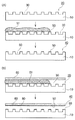
- FIG. 1 is a diagram schematically showing steps (a) and (b) in an embodiment of the method for producing a typical cell development microchamber chip (40) or (41) of the present invention.
- FIG. 2 (A) shows (b-1) of step (b) in one embodiment of the production method according to the present invention
- FIG. 2 (B) shows (b) of step (b) in one embodiment of the production method according to the present invention.
- FIG. 2 (C) shows step (b-3) of step (b) in one embodiment of the production method according to the present invention
- FIG. 2 (D) shows one embodiment of the production method according to the present invention.
- FIG. 4 is a diagram schematically showing (b-4) in step (b). The arrow in FIG.
- FIG. 3 (A) is a diagram illustrating FIG. 2 (A) in more detail.
- FIG. 3 (B) is a top plate (60) above the microchamber chip (20) in FIG. 3 (A).
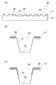
- FIG. 5 is a view showing a mode in which a flow path (80) is formed by arranging FIG. 4 (A) is obtained by the production method according to the present invention.
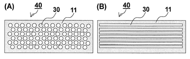
- FIG. 5 is a schematic view seen from above the microchamber for cell deployment (40), showing the case where the opening of the microchamber (30) is circular (A) and the case where it is rectangular (B).
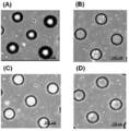
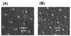
- 6 (A) and (B) show the results of Example 1
- FIGS. 6 (C) and (D) show the results of Comparative Example 1.
- Example 7 shows a PMT (photomultiplier tube) obtained by scanning across some of the specific microchambers (opening diameter: 100 ⁇ m) of the microchamber chip for cell deployment after intermittent liquid feeding in Example 1. The graph which plotted the signal is shown. A large peak observed at a “position” over a range of about 100 to 200 ⁇ m on the horizontal axis represents a signal derived from CTC.
- 8A shows the result of Example 4
- FIG. 8B shows the result of Comparative Example 2.
- FIGS. 9A and 9B both show the results of Example 4.
- a ⁇ microchamber chip for cell deployment '' (40) coated with a ⁇ blocking agent '' (50) that can be suppressed, or the upper surface (11) and the inner wall surface of the microchamber (30) include the blocking agent (50 ) -Coated “microchamber chip for cell deployment” (41), characterized in that it includes the following steps (a) and (b).
- the inner wall surface (31) refers to a portion (side surface) excluding the bottom surface (32) among the surfaces constituting the microchamber (30).
- the blocking agent (50) may cover the entire inner wall surface (31) of the microchamber (30) from the opening to the bottom, or may partially cover the middle from the opening to the bottom. It may be.
- the bottom surface (32) is not covered with the blocking agent (50) so that the cells once stored in the microchamber (30) do not escape by the subsequent liquid feeding.
- Step (a) is a step of manufacturing the microchamber chip (20) by forming the microchamber (30) on the upper surface (11) of the substrate (10).
- the contact angle between water and the substrate is measured by dropping water onto the substrate using a dynamic contact angle meter (“FTA125” manufactured by FTA)
- the contact angle is preferably 20 ° or more, more preferably 30 ° or more.
- the contact angle of 20 degrees or more means that the hydrophilicity of the substrate to be contacted with a blocking treatment liquid (in many cases, an aqueous solution) described later is not so strong.
- the blocking treatment solution is preferable because it does not excessively enter the inside of the microchamber (30) and cover the bottom surface (32).
- the opening of the microchamber (30) When the opening of the microchamber (30) is circular, its diameter may be about 500 ⁇ m, and since the cell holding power of the microchamber (30) is particularly strong, it is preferably 20 ⁇ m or more and 150 ⁇ m or less. . When the opening of the microchamber (30) is other than a circle, it is preferable to have an area equivalent to a circle having a diameter in the above range.
- the depth of the microchamber (30) can be appropriately determined depending on the diameter of the microchamber (30).
- the depth of the microchamber (30) is not less than 20 ⁇ m and not more than 100 ⁇ m.
- the blocking treatment liquid can maintain sufficient surface tension, and the microchamber (30 ) Can be prevented from reaching the bottom surface (32).
- the shape of the opening (horizontal cross section) of the microchamber (30) is typically circular as shown in FIG. 5 (A), but may be rectangular as shown in FIG. 5 (B). There is no particular limitation.
- the shape of the microchamber (30) is typically an inverted frustoconical shape (the longitudinal section shows a trapezoid as shown in FIG. 1) or a cylindrical shape (the longitudinal section shows a rectangle as shown in FIG. 3).
- the present invention is not limited to this embodiment.
- the area of the opening of the microchamber (30) is preferably larger than or equal to the area of the bottom surface (32), and the shape of such a microchamber (30) is other than the inverted frustoconical shape and the cylindrical shape.
- an inverted hemispherical shape, an inverted pyramid shape (an inverted polygonal cone such as an inverted quadrangular pyramid or an inverted hexagonal cone), a rectangular parallelepiped shape, and the like can be given.
- the microchamber chip (20) obtained in the step (a) is obtained by forming the microchamber (30) on the upper surface (11) of the substrate (10).
- a blocking agent in the following blocking treatment step (b)
- a blocking effect is brought about in this step (a) of forming the microchamber (30).
- a blocking treatment can be performed after performing a surface treatment that does not inhibit the effects of the present invention, for example, a surface treatment that enhances cell adhesion of the substrate, such as UV ozone treatment.
- Blocking step (b) Step (b), by contacting the blocking treatment liquid (51) containing the blocking agent (50) against the upper surface (11) of the microchamber chip (20) obtained in step (a), In the process of covering only the upper surface (11) of the substrate (10) or the upper surface (11) of the substrate (10) and the inner wall surface (a part or all) of the microchamber (30) with the blocking agent (50). is there.
- Specific examples of the embodiment of the blocking treatment step (b) include, for example, the following four methods (b-1) to (b-4) described below.
- the blocking agent (50) refers to a substance that covers the upper surface (11) of the substrate (10) and thereby suppresses nonspecific adsorption of cells thereto.
- the blocking treatment liquid (51) refers to a solution prepared by diluting the blocking agent (50) with an appropriate solvent, which is used when the blocking treatment step (b) of the present invention is performed. 50) is contained (for example, including modes such as dissolution and dispersion).
- the solvent for diluting the blocking agent may be selected appropriately according to the blocking agent.
- a solvent compatible with a biological substance similar to the solvent in which cells to be spread are suspended is preferable.
- PBS phosphate buffered saline
- HEPES HEPES
- MEM fetal calf serum
- RPMI phosphate buffer and the like.
- the means for flowing down the blocking treatment liquid is not particularly limited.
- a liquid feeding means such as a liquid feeding pump.
- the microchamber chip (20) can be inclined, or the blocking treatment liquid can be sucked from the downstream side using a suction means (for example, a water absorbing member such as filter paper).
- the feeding rate (flow rate) of the blocking treatment liquid is preferably 0.1 to 1,000 mm / sec. If the flow rate is within this range, the blocking treatment solution excessively penetrates into the microchamber (30), and the bottom surface ( It is easy to prevent blocking processing until 32). If the contact angle between water (in many cases the blocking solution is an aqueous solution) and the substrate (10) is greater than 20 degrees, the flow rate of the liquid can be adjusted within a range of less than 1 mm / sec. is there. In the flow velocity control method in the flow channel, the flow velocity on the surface of the substrate and the flow velocity at the central portion of the flow channel (intermediate point between the top plate and the top surface of the substrate) may be different.
- the flow rate substantially corresponds to the flow rate at the center of the flow path.
- the flow rate is the flow rate at the pump that sends the liquid.
- a flow rate of 0.1 to 1,000 mm / sec is 0.003 to 30 mL / Corresponds to a minute flow rate.
- the flow rate of the blocking treatment liquid can ensure the contact time that the blocking agent can sufficiently cover the substrate (10) by the width along the flow direction of the region where the microchamber (30) is formed. It is preferable to adjust to.
- the contact time at this time is preferably adjusted in the range of 10 seconds to 1 hour.
- the blocking agent (50) can be applied only to the upper surface (11) of the substrate (10) as shown in FIG. 4 (B), and by making the contact time relatively long
- a blocking agent can be applied to the inner wall surface (31) of the microchamber (30).
- the surface of the silicone rubber made of polydimethylsiloxane [PDMS] is subjected to UV ozone treatment or the like to be modified to be hydrophilic, thereby forming the stamped meat (71).
- a method of immersing in a blocking solution (51) such as PBS in which BSA is dissolved.
- (Simple addition method (b-3)) (b-3) is also referred to as a simple addition method, and is a method in which the blocking treatment liquid (51) is dropped over the entire upper surface (11) of the substrate (10) as shown in FIG. 2 (C). It is mainly applied to an open microchamber chip (20) that does not include a top plate (60). The upper surface (11) of the substrate (10) is covered by the dropped blocking treatment liquid (51), but the blocking treatment liquid (51) is contained inside the microchamber (30) by the surface tension of the blocking treatment liquid (51). Don't go too far.
- the blocking treatment liquid (51) is an aqueous solution, the contact angle between water and the substrate can be mentioned as control of the degree of entry into the microchamber (30).
- the contact angle is 100 degrees, only the upper surface of the substrate is blocked, but when the contact angle is 80 degrees or less, the blocking solution (51) starts to enter the microchamber (30), and the microchamber (30) A part of the inner wall surface (31) is blocked.
- the contact angle is preferably 20 degrees or more and 100 degrees or less, and further to the inside of the microchamber (30). In order to perform the blocking treatment, 20 degrees or more and 80 degrees or less is more preferable.
- the time for maintaining the state in which the upper surface (11) of the substrate (10) is covered with the blocking treatment liquid (51) is the same as the contact time in the flow rate control method (b-1) as described above. It can adjust suitably within the range.
- the dropped blocking treatment solution may be removed from the substrate (10).
- the time for immersing the inverted microchamber chip (20) in the blocking solution (51) is appropriately adjusted within the same range as the contact time in the flow rate control method (b-1) as described above. can do.
- the deeper the immersion the deeper the blocking treatment liquid (51) enters the microchamber (30), but the surface tension of the blocking treatment liquid (51) and the bubbles present in the microchamber (30). Therefore, the blocking solution (51) does not come into contact with the bottom surface (32) of the microchamber (30).
- the desired depth of immersion varies depending on the depth and shape of the microchamber (30) itself, but those skilled in the art can appropriately adjust it.
- ⁇ Microchamber chip for cell deployment> As shown in FIG. 1 and FIG. 4 (A), according to the manufacturing method of the present invention, the microchamber chip for cell expansion (40) in which only the upper surface (11) of the substrate (10) is subjected to blocking treatment, A cell developing microchamber chip (41) subjected to blocking treatment to the inner wall surface (31) of the chamber (30) or a cell developing microchamber chip (42) including these two embodiments is obtained.
- FIG. 4 (B) and (C) When the microchamber (30) of the microchamber chip for cell deployment (40) and (41) is enlarged, it is shown as FIG. 4 (B) and (C), respectively, and particularly as shown in FIG. 4 (C), If blocking treatment is applied to a part of the inner wall surface (31) of the microchamber (30), the expanded cells will not be adsorbed to the edge of the microchamber (30). At this time, the cells held on the edge and the bottom surface (32) of the micro chamber (30) can be observed without being overlapped, which is preferable.
- Example 1 Flow rate control method in the flow path (step (b-1) of the process using the top plate (b-1)) ⁇ Preparation of cell suspension> Mononuclear cells were separated from 1 mL of peripheral blood collected from cancer patients using “Ficoll-Paque (registered trademark) PREMIUM” (manufactured by GE Healthcare Japan), and paraformaldehyde (Wako Pure Chemical Industries, Ltd.) )) was added to 4%, gently mixed, and allowed to react in the dark at room temperature for 15 minutes. A sufficient amount of PBS was added thereto and mixed, followed by washing by centrifugation.
- PREMIUM registered trademark
- PBS paraformaldehyde
- a microchamber chip (length ⁇ width: 25 mm ⁇ 70 mm) was produced from a polystyrene substrate using a predetermined mold.
- the diameter of the opening of the microchamber was 100 ⁇ m
- the depth of the microchamber was 50 ⁇ m
- the shape of the microchamber was an inverted cone with a flat bottom surface.
- UV ozone treatment was performed for 1 minute with a UV ozone cleaner manufactured by Meiwa Forsys, and the contact angle of the microchamber chip and water was measured with a dynamic contact angle meter (FTA105) manufactured by FTA. there were.
- FTA105 dynamic contact angle meter
- a top plate was disposed on the microchamber chip, and the microchamber chip was separated from the top surface of the microchamber chip by 100 ⁇ m from the top surface. Moreover, the side wall was provided so that the width
- PBS containing 3% BSA As a blocking treatment solution, 1 mL of PBS containing 3% by weight of BSA (hereinafter also referred to as “PBS containing 3% BSA”) was introduced into the flow path at a flow rate of 1 mm / second. Thereafter, 10 mL of PBS, 1 mL of 70% ethanol, and 10 mL of PBS were sequentially fed at a flow rate of 1 mm / sec to obtain a microchamber chip for cell development.
- FIG. 6 shows the results of observation and imaging of the microchamber chip for cell development in the bright field of the microscope after blocking treatment (A) and after intermittent liquid feeding 20 times (B). As apparent from FIG. 6 (B), few cells remained outside the microchamber (that is, the upper surface of the microchamber chip) after 20 intermittent liquid feedings. As a result of counting the number of cells removed and discharged from the flow path by intermittent liquid feeding for 20 times, it was 1% or less of the initial number of cells introduced into the flow path.
- the microchamber chip for cell expansion after repeating intermittent feeding 20 times is irradiated with a He—Ne laser (wavelength 633 nm) for exciting Alexa Fluor (registered trademark) 647 labeled for CTC labeling.
- a He—Ne laser wavelength 633 nm
- Alexa Fluor registered trademark
- Example 2 Flow rate control method in flow path
- Example 1 instead of intermittent liquid feeding repeated 20 times after cell deployment, the same as Example 1 except that continuous liquid feeding was performed at 0.01 mm / second for 30 minutes after cell development. Then, the microchamber chip for cell deployment was imaged in a bright field of a microscope, and a CTC signal was detected. These results were almost the same as those in Example 1.
- Example 3 Flow rate control method in flow path In Example 1, in place of intermittent liquid feeding repeated 20 times after cell expansion, except for performing 10 times of reciprocal liquid feeding every 5 minutes at 0.1 mm / second after cell expansion. In the same manner as in 1, the cell development microchamber chip was imaged in a bright field of a microscope, and a CTC signal was detected. These results were almost the same as those in Example 1.
- Example 1 In the blocking treatment of Example 1, before introducing 3% BSA-containing PBS into the flow path, 1 mL of 70% ethanol and 10 mL of PBS were sent and the inside of the microchamber was wetted in advance, as in Example 1. Then, blocking treatment was performed. Thereby, a microchamber chip for cell deployment in which not only the inner wall surface but also the bottom surface of the microchamber was coated with BSA was obtained.
- FIG. 6 shows the results of observing and imaging the microchamber chip before cell expansion (C) and after repeating intermittent liquid feeding 20 times in the bright field of the microscope.
- C cell expansion
- D intermittent liquid feeding
- Example 1 When comparing the results of Example 1 and Comparative Example 1, when the microchamber of the microchamber chip for cell deployment manufactured by the flow rate control method in the flow path of Example 1 was used, it was stored in the macrochamber. It can be seen that the deviation of the cells was remarkably suppressed.
- a smooth surface of PDMS silicone rubber is modified to be hydrophilic by 60 minutes of UV ozone treatment (“PC440” manufactured by Meiwa Forsys), and then immersed in PBS containing 3% BSA for 1 hour.
- PC440 UV ozone treatment
- a stamp was prepared.
- Fig. 8 (A) shows the result of observation and imaging of a microchamber chip for cell expansion in a bright field of a microscope after introducing the cell suspension into the channel and allowing it to stand for 5 minutes, and then intermittently delivering the cell 20 times. Indicates.
- Example 5 Simple addition method (process (b) (b-3)) In Example 1, except that the blocking treatment was performed as follows, a channel was formed to expand cells and detect cells in the same manner as in Example 1.
- Example 4 ⁇ Cell development> Moreover, in Example 4, except that the cell suspension was changed to a PBS solution of Jurkat cells (1 ⁇ 10 7 cells / mL), each of these microchamber chips for cell deployment was used in the same manner as in Example 4. A flow channel was provided, cell expansion was performed, and images were observed and imaged in a bright field of a microscope. These results are also shown in FIG.
- the stamp time is 10 seconds
- cells may also adhere to the inner wall surface of the microchamber and overlap with the cells on the bottom surface, making it difficult to observe, whereas when the stamp time is 20 minutes, It can be seen that since the wall surface is also subjected to the blocking treatment, the cells accumulate on the bottom surface and are easily observed.
- micro chamber chip 10 ... substrate 11 ... upper surface 20 ... micro chamber chip 30 ... micro chamber 31 ... inner wall surface of micro chamber (30) 32 ... micro chamber (30) Bottom surface 40,41,42 ... Microchamber chip for cell deployment 50 ... Blocking agent 51 ... Blocking solution 60 ... Top plate 70 ... Stamp 71 ... Mark Meat 80 ⁇ ⁇ ⁇ ⁇ Channel
Landscapes
- Health & Medical Sciences (AREA)
- Life Sciences & Earth Sciences (AREA)
- Wood Science & Technology (AREA)
- Organic Chemistry (AREA)
- Engineering & Computer Science (AREA)
- Bioinformatics & Cheminformatics (AREA)
- Chemical & Material Sciences (AREA)
- Zoology (AREA)
- Biomedical Technology (AREA)
- Sustainable Development (AREA)
- Microbiology (AREA)
- Biotechnology (AREA)
- Biochemistry (AREA)
- General Engineering & Computer Science (AREA)
- General Health & Medical Sciences (AREA)
- Genetics & Genomics (AREA)
- Immunology (AREA)
- Molecular Biology (AREA)
- Apparatus Associated With Microorganisms And Enzymes (AREA)
- Sampling And Sample Adjustment (AREA)
Description
本発明は、少なくともマイクロチャンバーの底面にはブロッキング処理が施されていない細胞展開用マイクロチャンバーチップの製造方法に関する。
循環腫瘍細胞〔CTC〕、血管内皮細胞、血管内皮前駆細胞、各種幹細胞等(本明細書において、まとめて「希少細胞」という。)は病態に応じて全血中に極めて稀に存在する細胞である。希少細胞の検出は臨床的な有用性が明らかであるにもかかわらず、その検出は極めて難しい。近年様々な細胞分離手法を応用してその検出が試みられ製品化がなされているが、いずれにおいても対象の希少性が故、検出結果の有効性を評価(希少細胞のロスや不要細胞の混入の有無)することが重要である。
例えば採血した血液などの検体中に目的とする希少細胞が存在するか否かを検査する際、血液由来検体などの細胞懸濁液を平面状に展開した後、展開された全細胞を解析することによって、細胞懸濁液中に目的細胞が存在するか否かがわかる。
細胞懸濁液を平面状に展開する際、平面として例えば特許文献1に開示された化学マイクロデバイスを使用すると、該デバイス表面に形成されている微細な凹部(マイクロウェルまたはマイクロチャンバー)の中に細胞を高密度で格納することができ、該凹部ごとに細胞を検出することができる。また、一個一個の該凹部からそれぞれ細胞を回収し、さらなる検査に供することができる。特許文献1の化学マイクロデバイスは、励起光による蛍光の発生が少ないプラスチック材料を用いて射出成形により容易に製造することができる。しかしながら、この化学マイクロデバイスを使用して細胞展開した際、該凹部以外の表面に細胞が吸着しやすいため、展開した細胞を該凹部で充分に回収できず、希少細胞をロスするおそれがある。
一方、特許文献2には、ターゲット物質を一つ一つ個別的に固定化することができる微細穴を有するバイオチップ、およびその製造方法が開示されている。特許文献2のバイオチップでは、基盤を、エチレンジアミン〔EDA〕により表面処理した後、金属の薄膜(金薄膜)を重層することによって、細胞の非特異的な吸着を抑制している。微細穴の形成は、金属の薄膜の重層後に行われ、具体的にはFIB〔集束イオンビーム〕を金属の薄膜に照射し、該金属薄膜をその下の基盤ごと削り取ることによって、微細穴を形成する。また、特許文献2には、例えば、ターゲット物質を「該当する抗原認識領域を発現させたリンパ球細胞」とする場合、固定化物質としては「各種抗体」を選択すればよいことが記載されている。
しかしながら、特許文献2の製造方法では、大掛りな装置や複数の製造工程を必要とするため製造コストが掛ることに加え、表面処理後に加工する工程を伴うため、エチレンジアミンおよび金属薄膜による細胞の非特異的な吸着の抑制効果の劣化が非常に懸念される。また、特許文献2のバイオチップは、例えば同じ種類の細胞一個一個を微細穴一つ一つに固定化することができるが、その種類や大きさが異なり細胞数も膨大な集団からなる血液などから希少細胞を検出することを目的としたものではない。
本発明は、細胞がマイクロチャンバー以外の表面に非特異的に吸着するのを抑制し、例えば血液などの多量の細胞を含むものの中から希少細胞をもらさず格納、保持し観察することができる細胞展開用マイクロチャンバーチップを、少ない工程数で簡便に製造することを目的とする。
本発明者らは、マイクロチャンバーチップの表面に、ウシ血清アルブミン〔BSA〕の水溶液などのようなブロッキング処理液を当接させても、その表面張力によってマイクロチャンバー内に過度には浸入しないため、マイクロチャンバー以外の表面、好ましくはさらにマイクロチャンバーの内壁部を容易にブロッキング処理することができることを見出し、本発明を完成するに至った。
すなわち、上述した目的のうち少なくとも一つを実現するため、本発明の細胞展開用マイクロチャンバーチップの製造方法は、図1によると、一個以上の細胞を格納、保持することができるマイクロチャンバー(30)が基板(10)の上面(11)に形成されているマイクロチャンバーチップ(20)の上面(11)のみが、細胞が該上面(11)に非特異的に吸着するのを抑制できるブロッキング剤(50)で被覆された細胞展開用マイクロチャンバーチップ(40)、または、該上面(11)と該マイクロチャンバー(30)の内壁面(31)とが、該ブロッキング剤(50)で被覆された細胞展開用マイクロチャンバーチップ(41)を製造する方法であって、
(a):基板(10)の上面(11)に該マイクロチャンバー(30)を形成することによって、マイクロチャンバーチップ(20)を製造する工程;および、
(b):上記工程(a)で得られたマイクロチャンバーチップ(20)の上面(11)に対して、上記ブロッキング剤(50)を含有するブロッキング処理液(51)を当接することによって、該上面(11)のみを、または、該上面(11)と該マイクロチャンバー(30)の内壁面とを該ブロッキング剤(50)で被覆する工程、を含む。
(a):基板(10)の上面(11)に該マイクロチャンバー(30)を形成することによって、マイクロチャンバーチップ(20)を製造する工程;および、
(b):上記工程(a)で得られたマイクロチャンバーチップ(20)の上面(11)に対して、上記ブロッキング剤(50)を含有するブロッキング処理液(51)を当接することによって、該上面(11)のみを、または、該上面(11)と該マイクロチャンバー(30)の内壁面とを該ブロッキング剤(50)で被覆する工程、を含む。
本発明によると、マイクロチャンバー(30)形成後の基板(10)(すなわち、マイクロチャンバーチップ(20))に対して、その上面(11)特異的に細胞非接着性表面処理(「ブロッキング処理」ともいう。)を、容易に施すことができる。
すなわち、本発明は、マイクロチャンバーチップ(20)のマイクロチャンバー(30)以外の表面(さらには、マイクロチャンバー(30)の底面以外の表面)に対するブロッキング処理をたった一工程で実施することができる製造方法である。
すなわち、本発明は、マイクロチャンバーチップ(20)のマイクロチャンバー(30)以外の表面(さらには、マイクロチャンバー(30)の底面以外の表面)に対するブロッキング処理をたった一工程で実施することができる製造方法である。
本発明の製造方法により得られた細胞展開用マイクロチャンバーチップ(40)および(41)は、それを用いて細胞展開した際、ほぼすべての細胞をマイクロチャンバー(30)内に格納することができる。特に、マイクロチャンバー(30)の内壁面までブロッキングされた細胞展開用マイクロチャンバーチップ(41)を細胞展開に用いると、細胞がマイクロチャンバー(30)の内壁に吸着することなく底面に集積しやすいため、顕微鏡下の明視野による細胞観察が容易となる。
さらに、本発明ではマイクロチャンバー(30)の底面に対してはブロッキング処理を施さず、細胞が吸着しやすい状態が保持されているため、マイクロチャンバー(30)の底面に集積した細胞がその後の送液操作によって脱出してしまうことは極めて起こりにくい。そのため、細胞表面の抗原を認識する抗体のような固定化物質を用いることなく、希少細胞のロスを防止することができ、細胞観察の信頼性を向上させることが可能となる。
さらに、本発明ではマイクロチャンバー(30)の底面に対してはブロッキング処理を施さず、細胞が吸着しやすい状態が保持されているため、マイクロチャンバー(30)の底面に集積した細胞がその後の送液操作によって脱出してしまうことは極めて起こりにくい。そのため、細胞表面の抗原を認識する抗体のような固定化物質を用いることなく、希少細胞のロスを防止することができ、細胞観察の信頼性を向上させることが可能となる。
以下、本発明について、より詳細に説明する。
<細胞展開用マイクロチャンバーチップの製造方法>
図1に示されるように、本発明の「細胞展開用マイクロチャンバーチップ」(40または41)の製造方法は、一個以上の細胞を格納、保持することができる「マイクロチャンバー」(30)が「基板」(10)の「上面」(11)に形成されている「マイクロチャンバーチップ」(20)の該上面(11)のみが、細胞が該上面(11)に非特異的に吸着するのを抑制できる「ブロッキング剤」(50)で被覆された「細胞展開用マイクロチャンバーチップ」(40)、または、該上面(11)と該マイクロチャンバー(30)の内壁面とが、該ブロッキング剤(50)で被覆された「細胞展開用マイクロチャンバーチップ」(41)を製造する方法であって、後述する工程(a)および(b)を含むことを特徴とする。
<細胞展開用マイクロチャンバーチップの製造方法>
図1に示されるように、本発明の「細胞展開用マイクロチャンバーチップ」(40または41)の製造方法は、一個以上の細胞を格納、保持することができる「マイクロチャンバー」(30)が「基板」(10)の「上面」(11)に形成されている「マイクロチャンバーチップ」(20)の該上面(11)のみが、細胞が該上面(11)に非特異的に吸着するのを抑制できる「ブロッキング剤」(50)で被覆された「細胞展開用マイクロチャンバーチップ」(40)、または、該上面(11)と該マイクロチャンバー(30)の内壁面とが、該ブロッキング剤(50)で被覆された「細胞展開用マイクロチャンバーチップ」(41)を製造する方法であって、後述する工程(a)および(b)を含むことを特徴とする。
本発明の製造方法によって得られる、図1に示す細胞展開用マイクロチャンバーチップ(40または41)は典型例であって、図4(A)に示されるように、上面(11)がブロッキング剤で被覆されたマイクロチャンバー(30)と、上面(11)および内壁面(31)がブロッキング剤(50)で被覆されたマイクロチャンバー(30)とが混在する細胞展開用マイクロチャンバーチップ(42)が得られてもよい。
なお、内壁面(31)は、マイクロチャンバー(30)を構成する面のうち底面(32)を除く部分(側面)を指す。ブロッキング剤(50)は、マイクロチャンバー(30)の内壁面(31)のうち、開口部から底部にかけて全部を被覆していてもよいし、開口部から底部にかけての途中までを部分的に被覆していてもよい。一方、底面(32)は、一旦マイクロチャンバー(30)の内部に格納された細胞がその後の送液によって脱出してしまわないよう、ブロッキング剤(50)で被覆しないようにする。
〔マイクロチャンバー形成工程(a)〕
工程(a)とは、基板(10)の上面(11)にマイクロチャンバー(30)を形成することによって、マイクロチャンバーチップ(20)を製造する工程である。
工程(a)とは、基板(10)の上面(11)にマイクロチャンバー(30)を形成することによって、マイクロチャンバーチップ(20)を製造する工程である。
マイクロチャンバーの形成方法は特に限定されるものではなく、従来公知の方法を用いることができるが、例えば、マイクロチャンバーの形状に対応する凸部を有する金型を用いて成形する方法やシリコーン樹脂等を用いて射出成形する方法、熱可塑性樹脂等のポリマーや金属、ガラスなどからなる基板に直接加工(例えばリソグラフィーによる微細加工、掘削加工、LIGAプロセスなど)を施しマイクロチャンバーを形成する方法などが挙げられる。工業的に量産できるという観点からは、金型を用いて成形する方法が好適である。
(基板)
本発明で用いる基板の材料としては、従来公知のマイクロプレート等と同じ材料を使用でき、また金型を用いて成形できる材料であってもよく、例えば、ポリスチレン、ポリエチレン、ポリプロピレン、ポリアミド、ポリカーボネート、ポリジメチルシロキサン〔PDMS〕、ポリメチルメタクリレート〔PMMA〕、環状オレフィンコポリマー〔COC〕などのポリマーが挙げられる。基板は、(金型成形された)ポリマーに、金属、ガラス、石英ガラスなどからなる基板を張り合わせたような複数の材料を組み合わせたものであってもよい。
本発明で用いる基板の材料としては、従来公知のマイクロプレート等と同じ材料を使用でき、また金型を用いて成形できる材料であってもよく、例えば、ポリスチレン、ポリエチレン、ポリプロピレン、ポリアミド、ポリカーボネート、ポリジメチルシロキサン〔PDMS〕、ポリメチルメタクリレート〔PMMA〕、環状オレフィンコポリマー〔COC〕などのポリマーが挙げられる。基板は、(金型成形された)ポリマーに、金属、ガラス、石英ガラスなどからなる基板を張り合わせたような複数の材料を組み合わせたものであってもよい。
水と基板との接触角は、動的接触角計(FTA社製「FTA125」)により基板に水を滴下して測定した場合、好ましくは20度以上、より好ましくは30度以上である。接触角が20度以上であることは、後述するブロッキング処理液(多くの場合、水系溶液である。)を接触させようとする基板の親水性がそれほど強くないことを表しており、本発明のブロッキング処理工程(b)においてブロッキング処理液がマイクロチャンバー(30)の内部に過度に侵入して底面(32)まで被覆してしまわないため好適である。
(マイクロチャンバー)
本発明におけるマイクロチャンバーとは、一個以上の細胞を「格納」し、「保持」することができる凹状の微細穴(マイクロウェル)をいう。ここで、「格納」とは、本発明の細胞展開用マイクロチャンバーチップ表面に細胞懸濁液を添加した際に細胞がマイクロチャンバーに入る(収容される)ことをいい、「保持」とは、マイクロチャンバーに格納された細胞が、細胞展開用マイクロチャンバーチップ表面に添加された染色液や洗浄液等によってマイクロチャンバー外に出ないことをいう。
本発明におけるマイクロチャンバーとは、一個以上の細胞を「格納」し、「保持」することができる凹状の微細穴(マイクロウェル)をいう。ここで、「格納」とは、本発明の細胞展開用マイクロチャンバーチップ表面に細胞懸濁液を添加した際に細胞がマイクロチャンバーに入る(収容される)ことをいい、「保持」とは、マイクロチャンバーに格納された細胞が、細胞展開用マイクロチャンバーチップ表面に添加された染色液や洗浄液等によってマイクロチャンバー外に出ないことをいう。
マイクロチャンバー(30)の開口部が円形である場合、その直径は、500μm程度であってもよく、マイクロチャンバー(30)の細胞保持力が特に強いことから、20μm以上150μm以下であるのが好ましい。なお、マイクロチャンバー(30)の開口部が円形以外の場合は、直径が上記範囲にある円と同等の面積となるようにすることが好ましい。
マイクロチャンバー(30)の深さは、マイクロチャンバー(30)の直径によって適宜決定することができる。好ましくは、マイクロチャンバー(30)の深さは、20μm以上100μm以下である。
マイクロチャンバー(30)の開口部の直径ないし面積と、マイクロチャンバー(30)の深さとの比率を適切な範囲で調整することにより、ブロッキング処理液に充分な表面張力を保持させ、マイクロチャンバー(30)の底面(32)にブロッキング処理液が到達してしまうことを抑制することができる。
マイクロチャンバー(30)の開口部(水平断面)の形は、典型的には、図5(A)に示されるように円形であるが、図5(B)のように長方形であってもよく、特に限定されるものではない。
マイクロチャンバー(30)の形状は、典型的には、逆円錐台形(縦断面は図1のように台形を示す。)または円柱形(縦断面は図3のように長方形を示す。)が、本発明ではこの態様に限定されるものではない。マイクロチャンバー(30)の開口部の面積は、底面(32)の面積より大きいまたは同等であるのが好ましく、そのようなマイクロチャンバー(30)の形状としては、上記逆円錐台形および円柱形以外にも、例えば、逆半球形、逆角錐形(逆四角形錐や逆六角形錐等の逆多角形錐)、直方体形などが挙げられる。
マイクロチャンバー(30)は、細胞を保持できるようであれば、細胞懸濁液の溶媒を除去することなどを目的として、底部を有さない(底部周辺の側壁で細胞を保持する)、あるいは底部の一部に穴が形成されているものであってもよいが、希少細胞をロスする危険性を極力低くする観点からは、有底である(すなわち貫通した穴ではない)ことが好ましい。また、マイクロチャンバー(30)の底面(32)は、典型的には平坦であるが、曲面であってもよい。
(マイクロチャンバーチップ)
工程(a)で得られるマイクロチャンバーチップ(20)は、基板(10)の上面(11)にマイクロチャンバー(30)が形成されたものである。本発明では、次のブロッキング処理工程(b)により基板(10)の上面(11)をブロッキング剤で被覆するので、マイクロチャンバー(30)を形成するこの工程(a)の段階ではブロッキング効果をもたらす処理(特に底面までブロッキング剤で被覆してしまうおそれのある処理)を行う必要はない。必要に応じて、本発明の作用効果を阻害しない範囲の表面処理、例えばUVオゾン処理のように基板の細胞接着性を高める表面処理を行った上で、ブロッキング処理を施すことができる。
工程(a)で得られるマイクロチャンバーチップ(20)は、基板(10)の上面(11)にマイクロチャンバー(30)が形成されたものである。本発明では、次のブロッキング処理工程(b)により基板(10)の上面(11)をブロッキング剤で被覆するので、マイクロチャンバー(30)を形成するこの工程(a)の段階ではブロッキング効果をもたらす処理(特に底面までブロッキング剤で被覆してしまうおそれのある処理)を行う必要はない。必要に応じて、本発明の作用効果を阻害しない範囲の表面処理、例えばUVオゾン処理のように基板の細胞接着性を高める表面処理を行った上で、ブロッキング処理を施すことができる。
〔ブロッキング処理工程(b)〕
工程(b)とは、工程(a)で得られたマイクロチャンバーチップ(20)の上面(11)に対して、ブロッキング剤(50)を含有するブロッキング処理液(51)を当接することによって、基板(10)の上面(11)のみ、または、基板(10)の上面(11)とマイクロチャンバー(30)の内壁面(の一部~全部)を、ブロッキング剤(50)で被覆する工程である。
ブロッキング処理工程(b)の実施形態の具体例として、例えば、以下に説明する(b-1)~(b-4)のような四つの方式が挙げられる。
工程(b)とは、工程(a)で得られたマイクロチャンバーチップ(20)の上面(11)に対して、ブロッキング剤(50)を含有するブロッキング処理液(51)を当接することによって、基板(10)の上面(11)のみ、または、基板(10)の上面(11)とマイクロチャンバー(30)の内壁面(の一部~全部)を、ブロッキング剤(50)で被覆する工程である。
ブロッキング処理工程(b)の実施形態の具体例として、例えば、以下に説明する(b-1)~(b-4)のような四つの方式が挙げられる。
(ブロッキング剤/ブロッキング処理液)
ブロッキング剤(50)とは、基板(10)の上面(11)を被覆することで、細胞がそこに非特異的に吸着するのを抑制する物質を指す。また、ブロッキング処理液(51)は、本発明のブロッキング処理工程(b)を行う際に用いられる、ブロッキング剤(50)を適当な溶媒で希釈することにより調製される溶液を指し、ブロッキング剤(50)を含有(例えば溶解や分散などの態様を包含する。)している。
ブロッキング剤(50)とは、基板(10)の上面(11)を被覆することで、細胞がそこに非特異的に吸着するのを抑制する物質を指す。また、ブロッキング処理液(51)は、本発明のブロッキング処理工程(b)を行う際に用いられる、ブロッキング剤(50)を適当な溶媒で希釈することにより調製される溶液を指し、ブロッキング剤(50)を含有(例えば溶解や分散などの態様を包含する。)している。
ブロッキング剤としては公知の物質を用いることができ、例えば、BSA、ポリエチレングリコール等の親水性高分子、リン脂質などの他に、エチレンジアミンやアセトニトリルなどの低分子化合物も挙げられ、一種単独で用いても二種以上併用してもよい。
ブロッキング剤を希釈するための溶媒は、ブロッキング剤に応じて適切なものを選択すればよい。例えば、ブロッキング剤としてBSAを用いる場合は、展開するための細胞が懸濁している溶媒と同様の、生体関連物質に適合する溶媒が好ましく、具体的には、リン酸緩衝生理食塩水〔PBS〕、HEPES、MEM、RPMI、リン酸緩衝液等が挙げられる。
〔流速制御方式 (b-1)〕
(b-1)は、流速制御方式ともいい、図2(A)および図3(A)に示すように、基板(10)の上面(11)の一端からブロッキング処理液(例えばBSA溶液)を送液する方式である。
(b-1)は、流速制御方式ともいい、図2(A)および図3(A)に示すように、基板(10)の上面(11)の一端からブロッキング処理液(例えばBSA溶液)を送液する方式である。
流速制御方式のより好ましい実施形態として、図3(B)に示されるように、基板(10)の上面(11)側に、マイクロチャンバーチップ(20)と平行になるように天板(60)を設けることによって「流路」を形成し、流路の一端からブロッキング処理液を送液する方式が挙げられる。本明細書において、このような実施形態を「流路内流速制御方式」と呼ぶことがある。流路内流速制御方式は、閉鎖系において、ブロッキング処理工程(b)に続けて、細胞の展開・染色・検出の各操作を行うことができるため好ましい。
流路内流速制御方式において、マイクロチャンバーチップ(20)の上面(11)と天板(60)の内面との距離(以下「天井の高さ」ともいう。)は、50μm以上1,000μm以下が好ましい。このような距離でマイクロチャンバーチップ(20)と天板(60)とが離間していると、適度な毛細管力も働いて、ブロッキング処理液を全面的に展開させて基板のみならず天板(60)の基板側表面も同時にブロッキング処理液を塗布することができるとともに、細胞懸濁液もマイクロチャンバーチップ(20)に全面的に展開させてマイクロチャンバー(30)に収めることができる。
流速制御方式において、ブロッキング処理液を流下させる手段は特に限定されるものではない。例えば、流路内流速制御方式では、送液ポンプのような送液手段を用いて閉鎖系内にブロッキング処理液(および細胞懸濁液)を送液することが好適である。また、閉鎖系としない場合には、マイクロチャンバーチップ(20)に傾斜をつけたり、下流側から吸引手段(例えば濾紙などの水分吸収部材)を用いてブロッキング処理液を吸引したりすることができる。
ブロッキング処理液の送液の速度(流速)は0.1~1,000mm/秒であることが好ましく、流速がこの範囲であるとブロッキング処理液がマイクロチャンバー(30)の内部に過度に侵入し、底面(32)までブロッキング処理されてしまうことを防止しやすくなる。水(多くの場合ブロッキング処理液は水性溶液である。)と基板(10)との接触角が20度より大きい場合は、送液の流速を1mm/秒より小さい範囲で調整することも可能である。なお、流路内流速制御方式において、基板表面の流速と流路中央部(天板と基板上面の中間地点)での流速は異なることがあるが、本発明では、ブロッキング処理液の送液の流速は、流路中央部の流速にほぼ該当するものである。一方、流量は送液するポンプでの流量になり、例えば、流路幅が5mm、天井の高さが100μmである流路を用いる場合、0.1~1,000mm/秒の流速は、0.003~30mL/分の流量に対応する。
また、ブロッキング処理液の流速は、マイクロチャンバー(30)が形成されている領域の流下方向に沿った幅によって、ブロッキング剤が基板(10)を充分に被覆することができる接触時間を確保できるように調整することが好ましい。この際の接触時間は、10秒間以上1時間以下の範囲で調整することが好ましい。接触時間を比較的短くすることにより、図4(B)のように基板(10)の上面(11)のみにブロッキング剤(50)を塗布することができ、接触時間を比較的長くすることにより、図4(C)のようにマイクロチャンバー(30)の内壁面(31)までブロッキング剤を塗布することができる。接触時間が過度に長いと、マイクロチャンバー(30)の底面(32)までブロッキング剤で被覆されるおそれがあり、接触時間が過度に短いと、ブロッキング剤が上面(11)や内壁面(31)に十分に付着せずブロッキング効果が弱くなるおそれがある。
〔スタンプ方式 (b-2)〕
(b-2)は、スタンプ方式ともいい、図2(B)で示されるように、ブロッキング処理液(51)を浸みこませた「印肉」(71)を有する「スタンプ」(70)を、基板(10)の上面(11)に接触(または押印)させる方式である。主に、天板(60)を備えない、開放系のマイクロチャンバーチップ(20)に対して適用される。また、流速制御方式(b-1)、単純添加方式(b-3)または単純浸漬方式(b-4)ではブロッキング処理を行いにくいマイクロチャンバーチップ(20)に対しても、このスタンプ方式(b-2)であれば適切にブロッキング処理できる場合がある。
(b-2)は、スタンプ方式ともいい、図2(B)で示されるように、ブロッキング処理液(51)を浸みこませた「印肉」(71)を有する「スタンプ」(70)を、基板(10)の上面(11)に接触(または押印)させる方式である。主に、天板(60)を備えない、開放系のマイクロチャンバーチップ(20)に対して適用される。また、流速制御方式(b-1)、単純添加方式(b-3)または単純浸漬方式(b-4)ではブロッキング処理を行いにくいマイクロチャンバーチップ(20)に対しても、このスタンプ方式(b-2)であれば適切にブロッキング処理できる場合がある。
スタンプ(70)の作製方法としては、例えば、ポリジメチルシロキサン〔PDMS〕からなるシリコーンゴムの平滑な表面にUVオゾン処理等を施し親水性に改質することによって印肉(71)を形成し、BSAが溶解したPBS等のブロッキング処理液(51)に浸漬させる方法などが挙げられる。
スタンプ(70)を基板(10)の上面(11)に押印する際の処理条件は、印肉に含浸させたブロッキング処理液がマイクロチャンバー(30)内部に過度に侵入せず、底面(32)までブロッキング処理されてしまわないよう、適切な範囲で調整することができる。例えば、適切な押印の圧力はスタンプの材質によっても変動し得るが、上述したようなPDMSからなるシリコーンゴムのスタンプ(または印肉)を用いる場合、100MPa/cm2以下の範囲で調整することが好ましい。また、押印の時間は、押印の圧力によっても変動し得るが、前述したような流速制御方式(b-1)における接触時間と同様の範囲内で適宜調整することができる。
〔単純添加方式 (b-3)〕
(b-3)は、単純添加方式ともいい、図2(C)に示されるように、基板(10)の上面(11)の全部にわたってブロッキング処理液(51)を滴下する方式である。主に、天板(60)を備えない、開放系のマイクロチャンバーチップ(20)に対して適用される。滴下されたブロッキング処理液(51)によって基板(10)の上面(11)が覆われるが、ブロッキング処理液(51)の表面張力によってマイクロチャンバー(30)の内部にはブロッキング処理液(51)は過度に入り込まない。ブロッキング処理液(51)が水性溶液である場合、マイクロチャンバー(30)の内部に入り込む度合いの制御として、水と基板との接触角が挙げられる。接触角が小さいほどブロッキング処理液(51)の入り込む度合いが高くなる。例えば、接触角が100度では、ほぼ基板上面のみがブロッキング処理されるが、接触角が80度以下ではブロッキング処理液(51)がマイクロチャンバー(30)の内部に入り込み始め、マイクロチャンバー(30)の内壁面(31)の一部がブロッキング処理される。マイクロチャンバー(30)の底面(32)にまでブロッキング処理液(51)が入り込まないようにするには、接触角としては20度以上100度以下が好ましく、さらにマイクロチャンバー(30)の内部までがブロッキング処理されるようにするためには20度以上80度以下がより好ましい。
(b-3)は、単純添加方式ともいい、図2(C)に示されるように、基板(10)の上面(11)の全部にわたってブロッキング処理液(51)を滴下する方式である。主に、天板(60)を備えない、開放系のマイクロチャンバーチップ(20)に対して適用される。滴下されたブロッキング処理液(51)によって基板(10)の上面(11)が覆われるが、ブロッキング処理液(51)の表面張力によってマイクロチャンバー(30)の内部にはブロッキング処理液(51)は過度に入り込まない。ブロッキング処理液(51)が水性溶液である場合、マイクロチャンバー(30)の内部に入り込む度合いの制御として、水と基板との接触角が挙げられる。接触角が小さいほどブロッキング処理液(51)の入り込む度合いが高くなる。例えば、接触角が100度では、ほぼ基板上面のみがブロッキング処理されるが、接触角が80度以下ではブロッキング処理液(51)がマイクロチャンバー(30)の内部に入り込み始め、マイクロチャンバー(30)の内壁面(31)の一部がブロッキング処理される。マイクロチャンバー(30)の底面(32)にまでブロッキング処理液(51)が入り込まないようにするには、接触角としては20度以上100度以下が好ましく、さらにマイクロチャンバー(30)の内部までがブロッキング処理されるようにするためには20度以上80度以下がより好ましい。
この方式において、ブロッキング処理液(51)によって基板(10)の上面(11)が覆われるような状態を保持する時間は、前述したような流速制御方式(b-1)における接触時間と同様の範囲内で適宜調整することができる。上記処理後、滴下されたブロッキング処理液は基板(10)上から取り除けばよい。
〔単純浸漬方式 (b-4)〕
(b-4)は、単純浸漬方式ともいい、図2(D)に示されるように、マイクロチャンバーチップ(20)を裏返し、基板(10)の上面(11)の全部にわたってブロッキング処理液(51)に浸す方式である。天板(60)を備える閉鎖系のマイクロチャンバーチップ(20)に適用する場合、天板(60)を配設する前に、天板(60)の一方の面または天板全部をブロッキング処理液(51)に浸せばよい。
(b-4)は、単純浸漬方式ともいい、図2(D)に示されるように、マイクロチャンバーチップ(20)を裏返し、基板(10)の上面(11)の全部にわたってブロッキング処理液(51)に浸す方式である。天板(60)を備える閉鎖系のマイクロチャンバーチップ(20)に適用する場合、天板(60)を配設する前に、天板(60)の一方の面または天板全部をブロッキング処理液(51)に浸せばよい。
この方式において、ブロッキング処理液(51)に、逆さにしたマイクロチャンバーチップ(20)を浸漬する時間は、前述したような流速制御方式(b-1)における接触時間と同様の範囲内で適宜調整することができる。また、浸漬する深さは、深ければ深いほどマイクロチャンバー(30)の内部にブロッキング処理液(51)が入り込むが、ブロッキング処理液(51)の表面張力とマイクロチャンバー(30)内に存在する気泡のため、マイクロチャンバー(30)の底面(32)にブロッキング処理液(51)が接触することはない。ただし、マイクロチャンバー(30)自体の深さや形状によって、浸漬する所望の深さが変動するが、当業者は適宜調整することができる。
<細胞展開用マイクロチャンバーチップ>
図1および図4(A)に示されるように、本発明の製造方法によって、基板(10)の上面(11)のみにブロッキング処理が施された細胞展開用マイクロチャンバーチップ(40)、さらにマイクロチャンバー(30)の内壁面(31)までブロッキング処理が施された細胞展開用マイクロチャンバーチップ(41)、または、それら二つの態様を含む細胞展開用マイクロチャンバーチップ(42)が得られる。
図1および図4(A)に示されるように、本発明の製造方法によって、基板(10)の上面(11)のみにブロッキング処理が施された細胞展開用マイクロチャンバーチップ(40)、さらにマイクロチャンバー(30)の内壁面(31)までブロッキング処理が施された細胞展開用マイクロチャンバーチップ(41)、または、それら二つの態様を含む細胞展開用マイクロチャンバーチップ(42)が得られる。
細胞展開用マイクロチャンバーチップ(40)および(41)が有するマイクロチャンバー(30)を拡大すると、それぞれ図4(B)および(C)のように示され、特に図4(C)のように、マイクロチャンバー(30)の内壁面(31)の一部までブロッキング処理が施されていると、展開された細胞がマイクロチャンバー(30)の縁に吸着することがないため、顕微鏡下での観察の際マイクロチャンバー(30)の縁と底面(32)とに保持された細胞どうしが重ならずに観察できるため好適である。
以下、本発明について実施例を挙げてさらに詳細に説明するが、本発明はこれらに限定されない。
[実施例1]
流路内流速制御方式(天板を用いる工程(b)の(b-1))
〈細胞懸濁液の調製〉
癌患者から採血された末梢血1mLから「Ficoll-Paque(登録商標) PREMIUM」(GEヘルスケア・ジャパン(株)製)を用いて単核球を分離し、パラホルムアルデヒド(和光純薬工業(株)製)を4%になるように加えて、緩やかに混和し、室温暗所にて15分間反応させた。ここに、PBSを充分量加えて混和し、遠心分離にて洗浄を行った。次に細胞膜透過処理用として0.1%Tween20を含むPBSを1mLと、CTC標識用としてAlexa Fluor(登録商標) 647で標識した抗CK抗体(Micromet社製)溶液10μLと、白血球標識用としてAlexa Fluor(登録商標) 488(インビトロジェン社製)で標識した抗CD45抗体(Santa Cruz Biotechnology, Inc.)溶液10μLとを添加し、緩やかに混和しながら、室温暗所にて30分間反応させた。最後の5分間は、細胞核染色用としてDAPI((株)同仁化学研究所製)溶液10μLを添加して反応させた。この後、遠心分離により細胞に結合していない抗体試薬を除去し、新たにPBSを1mL添加して再懸濁させ、「細胞懸濁液」を調製した。
[実施例1]
流路内流速制御方式(天板を用いる工程(b)の(b-1))
〈細胞懸濁液の調製〉
癌患者から採血された末梢血1mLから「Ficoll-Paque(登録商標) PREMIUM」(GEヘルスケア・ジャパン(株)製)を用いて単核球を分離し、パラホルムアルデヒド(和光純薬工業(株)製)を4%になるように加えて、緩やかに混和し、室温暗所にて15分間反応させた。ここに、PBSを充分量加えて混和し、遠心分離にて洗浄を行った。次に細胞膜透過処理用として0.1%Tween20を含むPBSを1mLと、CTC標識用としてAlexa Fluor(登録商標) 647で標識した抗CK抗体(Micromet社製)溶液10μLと、白血球標識用としてAlexa Fluor(登録商標) 488(インビトロジェン社製)で標識した抗CD45抗体(Santa Cruz Biotechnology, Inc.)溶液10μLとを添加し、緩やかに混和しながら、室温暗所にて30分間反応させた。最後の5分間は、細胞核染色用としてDAPI((株)同仁化学研究所製)溶液10μLを添加して反応させた。この後、遠心分離により細胞に結合していない抗体試薬を除去し、新たにPBSを1mL添加して再懸濁させ、「細胞懸濁液」を調製した。
〈マイクロチャンバーチップ〉
ポリスチレン製の基板から所定の金型を用いて、マイクロチャンバーチップ(縦×横が25mm×70mm)を作製した。このマイクロチャンバーの開口部の直径は100μm、マイクロチャンバーの深さは50μmであり、マイクロチャンバーの形状は底面が平坦な逆円錐形であった。
ポリスチレン製の基板から所定の金型を用いて、マイクロチャンバーチップ(縦×横が25mm×70mm)を作製した。このマイクロチャンバーの開口部の直径は100μm、マイクロチャンバーの深さは50μmであり、マイクロチャンバーの形状は底面が平坦な逆円錐形であった。
さらに、メイワフォーシス社製のUVオゾンクリーナーにてUVオゾン処理を1分間行い、マイクロチャンバーチップと水の接触角をFTA社製の動的接触角計(FTA105)にて測定した結果、70度であった。
その後、マイクロチャンバーチップに天板を配設し、マイクロチャンバーチップの上面から天板の内面まで100μm離間させた。また、流路の幅が5mmとなるように側壁を設けた。
〈ブロッキング処理〉
ブロッキング処理液として、BSAを3重量%含有するPBS(以下「3%BSA含有PBS」ともいう。)1mLを用いて、1mm/秒の流速で流路に導入した。その後、PBSを10mL、70%エタノールを1mL、さらにPBSを10mLの順に1mm/秒の流速で送液し、細胞展開用マイクロチャンバーチップを得た。
ブロッキング処理液として、BSAを3重量%含有するPBS(以下「3%BSA含有PBS」ともいう。)1mLを用いて、1mm/秒の流速で流路に導入した。その後、PBSを10mL、70%エタノールを1mL、さらにPBSを10mLの順に1mm/秒の流速で送液し、細胞展開用マイクロチャンバーチップを得た。
〈細胞展開〉
流路に満たされたPBSを置換するように、予め調製した細胞懸濁液200μLを1mm/秒の流速で流路に導入し、5分間静置させることによって、細胞を沈降させた。その後、余分の液体成分(細胞がほとんど除かれた細胞懸濁液)を流路から排出した。
流路に満たされたPBSを置換するように、予め調製した細胞懸濁液200μLを1mm/秒の流速で流路に導入し、5分間静置させることによって、細胞を沈降させた。その後、余分の液体成分(細胞がほとんど除かれた細胞懸濁液)を流路から排出した。
流路からPBSを1mm/秒の流速で0.1秒間導入した後に10秒間静置させるという「間欠送液」を20回繰り返した。
図6に、ブロッキング処理した後(A)と、間欠送液20回繰り返した後(B)との細胞展開用マイクロチャンバーチップをそれぞれ顕微鏡の明視野にて観察し撮像した結果を示す。図6(B)からも明らかなように、間欠送液20回後マイクロチャンバー外(すなわちマイクロチャンバーチップの上面)に残存した細胞はほとんどなかった。20回分の間欠送液により流路から除かれ排出された細胞数をカウントした結果、流路に導入された当初の細胞数の1%以下であった。
図6に、ブロッキング処理した後(A)と、間欠送液20回繰り返した後(B)との細胞展開用マイクロチャンバーチップをそれぞれ顕微鏡の明視野にて観察し撮像した結果を示す。図6(B)からも明らかなように、間欠送液20回後マイクロチャンバー外(すなわちマイクロチャンバーチップの上面)に残存した細胞はほとんどなかった。20回分の間欠送液により流路から除かれ排出された細胞数をカウントした結果、流路に導入された当初の細胞数の1%以下であった。
また、間欠送液を20回繰り返した後の細胞展開用マイクロチャンバーチップに、CTC標識用に標識したAlexa Fluor(登録商標) 647を励起するHe-Neレーザー(波長633nm)を照射し、該チップ上に展開された全細胞のシグナルを光電子倍増管〔PMT〕にて測定したところ、CTCのシグナルが検出された。その結果を図7に示す。
[実施例2]
流路内流速制御方式
実施例1において、細胞展開後に20回繰り返した間欠送液の代わりに、細胞展開後0.01mm/秒で30分間連続送液を実施した以外は、実施例1と同様にして細胞展開用マイクロチャンバーチップを顕微鏡の明視野にて撮像し、CTCのシグナルを検出した。これらの結果はいずれも実施例1とほぼ同じものであった。
流路内流速制御方式
実施例1において、細胞展開後に20回繰り返した間欠送液の代わりに、細胞展開後0.01mm/秒で30分間連続送液を実施した以外は、実施例1と同様にして細胞展開用マイクロチャンバーチップを顕微鏡の明視野にて撮像し、CTCのシグナルを検出した。これらの結果はいずれも実施例1とほぼ同じものであった。
[実施例3]
流路内流速制御方式
実施例1において、細胞展開後に20回繰り返した間欠送液の代わりに、細胞展開後0.1mm/秒で5分間ずつの往復送液を10回実施した以外は、実施例1と同様にして細胞展開用マイクロチャンバーチップを顕微鏡の明視野にて撮像し、CTCのシグナルを検出した。これらの結果はいずれも実施例1とほぼ同じものであった。
流路内流速制御方式
実施例1において、細胞展開後に20回繰り返した間欠送液の代わりに、細胞展開後0.1mm/秒で5分間ずつの往復送液を10回実施した以外は、実施例1と同様にして細胞展開用マイクロチャンバーチップを顕微鏡の明視野にて撮像し、CTCのシグナルを検出した。これらの結果はいずれも実施例1とほぼ同じものであった。
[比較例1]
実施例1のブロッキング処理において、3%BSA含有PBSを流路に導入する前に、70%エタノール1mLとPBS10mLとを送液し、予めマイクロチャンバー内を濡らしておいた以外は実施例1と同様にしてブロッキング処理を行った。これにより、マイクロチャンバーの内壁面のみならず底面までもがBSAで被覆された細胞展開用マイクロチャンバーチップが得られた。
実施例1のブロッキング処理において、3%BSA含有PBSを流路に導入する前に、70%エタノール1mLとPBS10mLとを送液し、予めマイクロチャンバー内を濡らしておいた以外は実施例1と同様にしてブロッキング処理を行った。これにより、マイクロチャンバーの内壁面のみならず底面までもがBSAで被覆された細胞展開用マイクロチャンバーチップが得られた。
そして、このようなマイクロチャンバーチップの上面およびマイクロチャンバーの内壁面および底面にブロッキング処理が施された細胞展開用マイクロチャンバーチップを用いて、実施例1と同様にして細胞展開を行い、細胞を観察した。
図6に、細胞展開前(C)と、間欠送液20回繰り返した後(D)とのマイクロチャンバーチップをそれぞれ顕微鏡の明視野にて観察し撮像した結果を示す。図6(D)からもわかるように、間欠送液20回後マイクロチャンバー内に細胞はほとんど格納されなかった。20回分の間欠送液により流路から除かれ排出された細胞数をカウントした結果、流路に導入された当初の細胞数の約99%以上に相当した。
実施例1と比較例1との結果を比較すると、実施例1の流路内流速制御方式で製造された細胞展開用マイクロチャンバーチップが有するマイクロチャンバーを用いた場合は、マクロチャンバー内に格納した細胞の逸脱を顕著に抑制できたことがわかる。
[実施例4]
スタンプ方式(工程(b)の(b-2))
実施例1において、ブロッキング処理を以下のようにして行った以外は実施例1と同様に細胞展開を行い、細胞を観察した。
スタンプ方式(工程(b)の(b-2))
実施例1において、ブロッキング処理を以下のようにして行った以外は実施例1と同様に細胞展開を行い、細胞を観察した。
〈ブロッキング処理〉
まず、PDMSからなるシリコーンゴムの平滑な表面を、60分間のUVオゾン処理(メイワフォーシス(株)製の「PC440」)により親水性に改質後、3%BSA含有PBSに1時間浸漬させることによってスタンプを作製した。
まず、PDMSからなるシリコーンゴムの平滑な表面を、60分間のUVオゾン処理(メイワフォーシス(株)製の「PC440」)により親水性に改質後、3%BSA含有PBSに1時間浸漬させることによってスタンプを作製した。
このスタンプをマイクロチャンバーチップに0.1MPa/cm2で15分間押しつけた。
その後、マイクロチャンバーチップ表面をPBSで洗浄することによって、細胞展開用マイクロチャンバーチップが得られた。実施例1と同様に流路を形成した。
図8(A)に、細胞懸濁液を流路に導入し5分間静置させた後、間欠送液20回繰り返した細胞展開用マイクロチャンバーチップを顕微鏡の明視野にて観察し撮像した結果を示す。
その後、マイクロチャンバーチップ表面をPBSで洗浄することによって、細胞展開用マイクロチャンバーチップが得られた。実施例1と同様に流路を形成した。
図8(A)に、細胞懸濁液を流路に導入し5分間静置させた後、間欠送液20回繰り返した細胞展開用マイクロチャンバーチップを顕微鏡の明視野にて観察し撮像した結果を示す。
[比較例2]
実施例4において、マイクロチャンバーチップに上述したようなブロッキング処理を施さなかった以外は実施例4と同様にして細胞展開を行い、細胞を観察した。
実施例4において、マイクロチャンバーチップに上述したようなブロッキング処理を施さなかった以外は実施例4と同様にして細胞展開を行い、細胞を観察した。
図8(B)に、細胞懸濁液を流路に導入し5分間静置させた後、間欠送液20回繰り返したマイクロチャンバーチップを顕微鏡の明視野にて観察し撮像した結果を示す。図8(B)のマイクロチャンバー外の細胞数をカウントした結果、流路に導入された当初の細胞数の約40%に相当した。
実施例4と比較例2との結果を比較すると、実施例4のスタンプ方式で製造された細胞展開用マイクロチャンバーチップは、マイクロチャンバー外に細胞をほとんど残存させないようにできることがわかる。
[実施例5]
単純添加方式(工程(b)の(b-3))
実施例1において、ブロッキング処理を以下のようにして行った以外は実施例1と同様にして、流路を形成して細胞展開を行い、細胞を検出した。
単純添加方式(工程(b)の(b-3))
実施例1において、ブロッキング処理を以下のようにして行った以外は実施例1と同様にして、流路を形成して細胞展開を行い、細胞を検出した。
〈ブロッキング処理〉
3%BSA含有PBS4mLを、マイクロチャンバーチップ表面の全部が被覆されるように滴下し、5分間静置した。その後PBSで洗浄した。
3%BSA含有PBS4mLを、マイクロチャンバーチップ表面の全部が被覆されるように滴下し、5分間静置した。その後PBSで洗浄した。
[実施例6]
スタンプ方式によるブロッキングの確認
実施例4のブロッキング処理において、3%BSA含有PBSの代わりに、BSAのAlexa Fluor488コンジュゲート(インビトロジェン社製)を0.5重量%含有するPBSを用いた点、および、スタンプをマイクロチャンバーチップに押印した時間をそれぞれ10秒間と20分間とに変更した点以外は実施例4と同様にして、それぞれ図9(A)および(B)に示すように、二種類の細胞展開用マイクロチャンバーチップを製造した。
スタンプ方式によるブロッキングの確認
実施例4のブロッキング処理において、3%BSA含有PBSの代わりに、BSAのAlexa Fluor488コンジュゲート(インビトロジェン社製)を0.5重量%含有するPBSを用いた点、および、スタンプをマイクロチャンバーチップに押印した時間をそれぞれ10秒間と20分間とに変更した点以外は実施例4と同様にして、それぞれ図9(A)および(B)に示すように、二種類の細胞展開用マイクロチャンバーチップを製造した。
図9の蛍光画像および蛍光強度の測定結果から、スタンプ時間が10秒間のように短い場合、基板表面だけがBSAで被覆されていることがわかった(図9(A))。一方、スタンプ時間が20分間のように長い場合、マイクロチャンバーの内壁面の一部までBSAで被覆されていることがわかった(図9(B))。
〈細胞展開〉
また、実施例4において、細胞懸濁液として、Jurkat細胞のPBS溶液(1×10⁷cells/mL)に変更した以外は実施例4と同様にして、これらの細胞展開用マイクロチャンバーチップにそれぞれ流路を設け、細胞展開を行い、顕微鏡の明視野にて観察し撮像した。これらの結果も図9に示す。
また、実施例4において、細胞懸濁液として、Jurkat細胞のPBS溶液(1×10⁷cells/mL)に変更した以外は実施例4と同様にして、これらの細胞展開用マイクロチャンバーチップにそれぞれ流路を設け、細胞展開を行い、顕微鏡の明視野にて観察し撮像した。これらの結果も図9に示す。
スタンプ時間が10秒間の場合、マイクロチャンバーの内壁面にも細胞が吸着し、底面にいる細胞と重なり観察しづらくなる場合があるのに対して、スタンプ時間が20分間の場合、マイクロチャンバーの内壁面にもブロッキング処理が施されているため、細胞が底面に集積し、観察しやすくなることがわかる。
10・・・・ 基板
11・・・・ 上面
20・・・・ マイクロチャンバーチップ
30・・・・ マイクロチャンバー
31・・・・ マイクロチャンバー(30)の内壁面
32・・・・ マイクロチャンバー(30)の底面
40,41,42・・・細胞展開用マイクロチャンバーチップ
50・・・・ ブロッキング剤
51・・・・ ブロッキング処理液
60・・・・ 天板
70・・・・ スタンプ
71・・・・ 印肉
80・・・・ 流路
11・・・・ 上面
20・・・・ マイクロチャンバーチップ
30・・・・ マイクロチャンバー
31・・・・ マイクロチャンバー(30)の内壁面
32・・・・ マイクロチャンバー(30)の底面
40,41,42・・・細胞展開用マイクロチャンバーチップ
50・・・・ ブロッキング剤
51・・・・ ブロッキング処理液
60・・・・ 天板
70・・・・ スタンプ
71・・・・ 印肉
80・・・・ 流路
Claims (11)
- 一個以上の細胞を格納、保持することができるマイクロチャンバー(30)が基板(10)の上面(11)に形成されているマイクロチャンバーチップ(20)の
上面(11)のみが、細胞が該上面(11)に非特異的に吸着するのを抑制できるブロッキング剤(50)で被覆された細胞展開用マイクロチャンバーチップ(40)、または、
該上面(11)と該マイクロチャンバー(30)の内壁面(31)とが、該ブロッキング剤(50)で被覆された細胞展開用マイクロチャンバーチップ(41)の製造方法であって、
(a):基板(10)の上面(11)に該マイクロチャンバー(30)を形成することによって、マイクロチャンバーチップ(20)を製造する工程;および、
(b):上記工程(a)で得られたマイクロチャンバーチップ(20)の上面(11)に対して、上記ブロッキング剤(50)を含有するブロッキング処理液(51)を当接することによって、該上面(11)のみを、または、該上面(11)と該マイクロチャンバー(30)の内壁面とを該ブロッキング剤(50)で被覆する工程を含む、製造方法。 - 上記工程(b)において、
(b-1):上記上面(11)の一端から上記ブロッキング処理液(51)を送液する、請求項1に記載の製造方法。 - 上記工程(b)において、
(b-2):上記ブロッキング処理液(51)を浸みこませた印肉(71)を該上面(11)に接触させる、請求項1に記載の製造方法。 - 上記工程(b)において、
(b-3):上記上面(11)の全部にわたって上記ブロッキング処理液(51)を滴下する、請求項1に記載の製造方法。 - 上記工程(b)において、
(b-4):上記上面(11)を上記ブロッキング処理液(51)に浸す、請求項1に記載の製造方法。 - 上記マイクロチャンバー(30)の開口部の直径が、20μm以上150μm以下であり、
上記マイクロチャンバー(30)の深さが、20μm以上100μm以下である、請求項1~5のいずれか一項に記載の製造方法。 - 上記マイクロチャンバー(30)が有底である、請求項1~6のいずれか一項に記載の製造方法。
- 上記工程(b)において、上記ブロッキング処理液(51)を上記上面(11)に当接させる時間が、10秒間以上1時間以下である、請求項1~7のいずれか一項に記載の製造方法。
- 上記(b-1)において、基板(10)の上面(11)側に、マイクロチャンバーチップ(20)と平行になるように天板(60)を設け、
基板(10)の上面(11)と天板(60)の内面とが、50μm以上1,000μm以下で離間している、請求項2および6~8のいずれか一項に記載の製造方法。 - 上記ブロッキング剤(50)が、ウシ血清アルブミン〔BSA〕、親水性高分子およびリン脂質からなる群から選択される少なくとも一種を含む、請求項1~9のいずれか一項に記載の製造方法。
- 水と基板(10)との接触角が20度以上である、請求項1~10のいずれか一項に記載の製造方法。
Priority Applications (1)
| Application Number | Priority Date | Filing Date | Title |
|---|---|---|---|
| JP2014523726A JP6198070B2 (ja) | 2012-07-03 | 2013-07-01 | 細胞展開用マイクロチャンバーチップの製造方法 |
Applications Claiming Priority (2)
| Application Number | Priority Date | Filing Date | Title |
|---|---|---|---|
| JP2012149406 | 2012-07-03 | ||
| JP2012-149406 | 2012-07-03 |
Publications (1)
| Publication Number | Publication Date |
|---|---|
| WO2014007191A1 true WO2014007191A1 (ja) | 2014-01-09 |
Family
ID=49881947
Family Applications (1)
| Application Number | Title | Priority Date | Filing Date |
|---|---|---|---|
| PCT/JP2013/067979 Ceased WO2014007191A1 (ja) | 2012-07-03 | 2013-07-01 | 細胞展開用マイクロチャンバーチップの製造方法 |
Country Status (2)
| Country | Link |
|---|---|
| JP (1) | JP6198070B2 (ja) |
| WO (1) | WO2014007191A1 (ja) |
Cited By (1)
| Publication number | Priority date | Publication date | Assignee | Title |
|---|---|---|---|---|
| WO2016140327A1 (ja) * | 2015-03-04 | 2016-09-09 | 国立研究開発法人産業技術総合研究所 | マイクロチャンバーアレイプレート |
Citations (3)
| Publication number | Priority date | Publication date | Assignee | Title |
|---|---|---|---|---|
| JP2004333404A (ja) * | 2003-05-12 | 2004-11-25 | Hitachi Ltd | マイクロリアクタ及びその製造方法、並びに試料スクリーニング装置 |
| JP2006262825A (ja) * | 2005-03-25 | 2006-10-05 | Tadashi Matsunaga | 微生物分離装置 |
| JP2011193758A (ja) * | 2010-03-18 | 2011-10-06 | National Institute Of Advanced Industrial Science & Technology | 薬剤感受性試験用バイオチップ |
-
2013
- 2013-07-01 WO PCT/JP2013/067979 patent/WO2014007191A1/ja not_active Ceased
- 2013-07-01 JP JP2014523726A patent/JP6198070B2/ja not_active Expired - Fee Related
Patent Citations (3)
| Publication number | Priority date | Publication date | Assignee | Title |
|---|---|---|---|---|
| JP2004333404A (ja) * | 2003-05-12 | 2004-11-25 | Hitachi Ltd | マイクロリアクタ及びその製造方法、並びに試料スクリーニング装置 |
| JP2006262825A (ja) * | 2005-03-25 | 2006-10-05 | Tadashi Matsunaga | 微生物分離装置 |
| JP2011193758A (ja) * | 2010-03-18 | 2011-10-06 | National Institute Of Advanced Industrial Science & Technology | 薬剤感受性試験用バイオチップ |
Cited By (2)
| Publication number | Priority date | Publication date | Assignee | Title |
|---|---|---|---|---|
| WO2016140327A1 (ja) * | 2015-03-04 | 2016-09-09 | 国立研究開発法人産業技術総合研究所 | マイクロチャンバーアレイプレート |
| JPWO2016140327A1 (ja) * | 2015-03-04 | 2017-12-14 | 国立研究開発法人産業技術総合研究所 | マイクロチャンバーアレイプレート |
Also Published As
| Publication number | Publication date |
|---|---|
| JPWO2014007191A1 (ja) | 2016-06-02 |
| JP6198070B2 (ja) | 2017-09-20 |
Similar Documents
| Publication | Publication Date | Title |
|---|---|---|
| US10866169B2 (en) | Method for recovering rare cells and method for detecting rare cells | |
| JP5620444B2 (ja) | 液滴中においてサンプルを処理するためのデバイスをリンスする装置、および当該デバイスをリンスする方法 | |
| CA2953666C (en) | Substance sealing method and target molecule detecting method | |
| JP6751970B2 (ja) | デジタル計数のためのフローシステムおよび方法 | |
| CN103649759A (zh) | 微流体装置以及制造方法和用途 | |
| US20170298314A1 (en) | Nano-droplet plate | |
| US10584367B2 (en) | Cell-spreading device and method for detecting rare cell | |
| JP6519482B2 (ja) | 細胞の蛍光免疫染色方法ならびにそのためのシステムおよびキット | |
| JP6198070B2 (ja) | 細胞展開用マイクロチャンバーチップの製造方法 | |
| JP6238208B2 (ja) | 細胞展開用マイクロチャンバーチップ | |
| JP2009031126A (ja) | マイクロ流路形成体を利用したマイクロビーズアレイ用チップ、マイクロビーズアレイ及びこれらを用いた被検物質を検出する方法。 | |
| US20250084360A1 (en) | Incubation method and sample holder | |
| JPH01202661A (ja) | 流れ増進性ディップスティック | |
| JPWO2016121574A1 (ja) | 相互作用する分子を有する血中細胞の同時検出方法 | |
| RS59611B1 (sr) | Novi poc sistem testiranja i metod | |
| JP2014109564A (ja) | 標的物質検出用マイクロチップ | |
| WO2015060446A1 (ja) | 膜小胞回収デバイス、膜小胞回収方法、及び膜小胞分析方法 | |
| JP6528378B2 (ja) | 細胞展開方法およびそのためのキット | |
| WO2017073533A1 (ja) | 稀少細胞を観察するための細胞展開方法および細胞展開用キット | |
| EP3256572A1 (en) | Immobilization of cells or virus particles on protein structures using a microfluidic chamber | |
| JP6172021B2 (ja) | 細胞整列チップ、その製造方法、標的細胞の検出方法、標的細胞の検出装置および細胞捕捉不良領域の検出方法 | |
| TW202045721A (zh) | 細胞接著用組合物及細胞接著用基材 | |
| JP2016148593A (ja) | 液体試料の検査方法 | |
| US20130095008A1 (en) | Tube and float systems and methods of using the same | |
| Man | Photothermal Intracellular Delivery Platforms |
Legal Events
| Date | Code | Title | Description |
|---|---|---|---|
| 121 | Ep: the epo has been informed by wipo that ep was designated in this application |
Ref document number: 13813688 Country of ref document: EP Kind code of ref document: A1 |
|
| ENP | Entry into the national phase |
Ref document number: 2014523726 Country of ref document: JP Kind code of ref document: A |
|
| NENP | Non-entry into the national phase |
Ref country code: DE |
|
| 122 | Ep: pct application non-entry in european phase |
Ref document number: 13813688 Country of ref document: EP Kind code of ref document: A1 |