WO2014007160A1 - 偏光板の製造方法および製造装置 - Google Patents
偏光板の製造方法および製造装置 Download PDFInfo
- Publication number
- WO2014007160A1 WO2014007160A1 PCT/JP2013/067806 JP2013067806W WO2014007160A1 WO 2014007160 A1 WO2014007160 A1 WO 2014007160A1 JP 2013067806 W JP2013067806 W JP 2013067806W WO 2014007160 A1 WO2014007160 A1 WO 2014007160A1
- Authority
- WO
- WIPO (PCT)
- Prior art keywords
- film
- adhesive
- polarizing film
- active energy
- polarizing
- Prior art date
- Legal status (The legal status is an assumption and is not a legal conclusion. Google has not performed a legal analysis and makes no representation as to the accuracy of the status listed.)
- Ceased
Links
Images


Classifications
-
- G—PHYSICS
- G02—OPTICS
- G02B—OPTICAL ELEMENTS, SYSTEMS OR APPARATUS
- G02B5/00—Optical elements other than lenses
- G02B5/30—Polarising elements
- G02B5/3025—Polarisers, i.e. arrangements capable of producing a definite output polarisation state from an unpolarised input state
- G02B5/3033—Polarisers, i.e. arrangements capable of producing a definite output polarisation state from an unpolarised input state in the form of a thin sheet or foil, e.g. Polaroid
-
- G—PHYSICS
- G02—OPTICS
- G02B—OPTICAL ELEMENTS, SYSTEMS OR APPARATUS
- G02B5/00—Optical elements other than lenses
- G02B5/30—Polarising elements
- G02B5/3025—Polarisers, i.e. arrangements capable of producing a definite output polarisation state from an unpolarised input state
- G02B5/3033—Polarisers, i.e. arrangements capable of producing a definite output polarisation state from an unpolarised input state in the form of a thin sheet or foil, e.g. Polaroid
- G02B5/3041—Polarisers, i.e. arrangements capable of producing a definite output polarisation state from an unpolarised input state in the form of a thin sheet or foil, e.g. Polaroid comprising multiple thin layers, e.g. multilayer stacks
-
- C—CHEMISTRY; METALLURGY
- C09—DYES; PAINTS; POLISHES; NATURAL RESINS; ADHESIVES; COMPOSITIONS NOT OTHERWISE PROVIDED FOR; APPLICATIONS OF MATERIALS NOT OTHERWISE PROVIDED FOR
- C09J—ADHESIVES; NON-MECHANICAL ASPECTS OF ADHESIVE PROCESSES IN GENERAL; ADHESIVE PROCESSES NOT PROVIDED FOR ELSEWHERE; USE OF MATERIALS AS ADHESIVES
- C09J5/00—Adhesive processes in general; Adhesive processes not provided for elsewhere, e.g. relating to primers
-
- C—CHEMISTRY; METALLURGY
- C09—DYES; PAINTS; POLISHES; NATURAL RESINS; ADHESIVES; COMPOSITIONS NOT OTHERWISE PROVIDED FOR; APPLICATIONS OF MATERIALS NOT OTHERWISE PROVIDED FOR
- C09J—ADHESIVES; NON-MECHANICAL ASPECTS OF ADHESIVE PROCESSES IN GENERAL; ADHESIVE PROCESSES NOT PROVIDED FOR ELSEWHERE; USE OF MATERIALS AS ADHESIVES
- C09J2203/00—Applications of adhesives in processes or use of adhesives in the form of films or foils
- C09J2203/318—Applications of adhesives in processes or use of adhesives in the form of films or foils for the production of liquid crystal displays
-
- C—CHEMISTRY; METALLURGY
- C09—DYES; PAINTS; POLISHES; NATURAL RESINS; ADHESIVES; COMPOSITIONS NOT OTHERWISE PROVIDED FOR; APPLICATIONS OF MATERIALS NOT OTHERWISE PROVIDED FOR
- C09J—ADHESIVES; NON-MECHANICAL ASPECTS OF ADHESIVE PROCESSES IN GENERAL; ADHESIVE PROCESSES NOT PROVIDED FOR ELSEWHERE; USE OF MATERIALS AS ADHESIVES
- C09J2301/00—Additional features of adhesives in the form of films or foils
- C09J2301/40—Additional features of adhesives in the form of films or foils characterized by the presence of essential components
- C09J2301/416—Additional features of adhesives in the form of films or foils characterized by the presence of essential components use of irradiation
-
- G—PHYSICS
- G02—OPTICS
- G02B—OPTICAL ELEMENTS, SYSTEMS OR APPARATUS
- G02B1/00—Optical elements characterised by the material of which they are made; Optical coatings for optical elements
- G02B1/10—Optical coatings produced by application to, or surface treatment of, optical elements
Definitions
- the present invention relates to a polarizing plate manufacturing method and a manufacturing apparatus useful as one of optical components constituting a liquid crystal display device or the like.
- Polarizing films are widely used as dichroic dyes adsorbed and oriented on polyvinyl alcohol resin films. Iodine polarizing films using iodine as a dichroic dye and dichroic direct dyes as dichroic Dye-type polarizing films used as pigments are known. These polarizing films are usually used as polarizing plates by laminating a transparent film such as a triacetyl cellulose film on one side or both sides via an adhesive.
- Patent Document 1 Japanese Patent Laid-Open No. 2004-245925
- Patent Document 2 Japanese Patent Laid-Open No. 2009-134190
- Patent Document 3 Special No. 2011-95560
- JP 2004-245925 A JP 2009-134190 A JP 2011-95560 A
- the thickness of the active energy ray-curable resin applied on the surface of the transparent film is, for example, 2.0 ⁇ m or less in order to reduce the thickness of the polarizing plate, the transparent film and the polarizing film are bonded. There was a problem that air bubbles were easily mixed in.
- the present invention has been made to solve the above-described problems, and provides a polarizing plate manufacturing method and a manufacturing apparatus in which mixing of bubbles is suppressed even when the thickness of the active energy ray-curable resin is reduced.
- the purpose is to do.
- the present invention relates to a method for producing a polarizing plate in which a transparent film is bonded to one side or both sides of a polarizing film, the adhesive coating applying an active energy ray-curable adhesive to one side or both sides of the polarizing film.
- the application thickness of the active energy ray-curable adhesive applied to one or both sides of the polarizing film is preferably 0.1 to 2.0 ⁇ m.
- the adhesive coating step is a step of applying an active energy ray-curable adhesive to one side or both sides of a polarizing film conveyed upward in the vertical direction.
- the adhesive coating step is a step of applying an active energy ray-curable adhesive to one side or both sides of a polarizing film conveyed downward in the vertical direction.
- the present invention is a polarizing plate manufacturing apparatus in which a transparent film is bonded to one side or both sides of a polarizing film, the transport means transporting the polarizing film upward in the vertical direction, and transported upward in the vertical direction.
- An adhesive coating device for applying an active energy ray-curable adhesive on one or both sides of a polarizing film, and a laminate in which a transparent film is laminated on one or both sides of the polarizing film via an adhesive
- an irradiation apparatus for applying an active energy ray-curable adhesive on one or both sides of a polarizing film, and a laminate in which a transparent film is laminated on one or both sides of the polarizing film via an adhesive
- a pair of laminating rolls for laminating a transparent film and a polarizing film, and an active energy
- the present invention is a polarizing plate manufacturing apparatus in which a transparent film is bonded to one side or both sides of a polarizing film, the transporting means for transporting the polarizing film downward in the vertical direction, and transported downward in the vertical direction.
- An adhesive coating device for applying an active energy ray-curable adhesive on one or both sides of a polarizing film, and a laminate in which the transparent film is laminated on one or both sides of the polarizing film via an adhesive
- an irradiation apparatus for applying an active energy ray-curable adhesive on one or both sides of a polarizing film, and a laminate in which the transparent film is laminated on one or both sides of the polarizing film via an adhesive
- a pair of laminating rolls for laminating a transparent film and a polarizing film, and an active energy
- the polarizing plate produced by the present invention is a polarizing plate in which a transparent film is bonded to one side or both sides of a polarizing film.
- an adhesive coating step of applying an active energy ray-curable adhesive on one side or both sides of a polarizing film and a transparent film are laminated on one side or both sides of the polarizing film via an adhesive.
- the laminated body is sandwiched between a pair of laminating rolls that rotate in the conveying direction and pressed, so that the laminating body is irradiated with active energy rays, and a laminating process for laminating the transparent film and the polarizing film.
- an active energy ray irradiation step for curing the adhesive First, each material used in the production method of the present invention will be described.
- the polarizing film used in the polarizing plate of the present invention is obtained by adsorbing and orienting a dichroic dye on a uniaxially stretched polyvinyl alcohol resin film.
- the polyvinyl alcohol-based resin can be obtained by saponifying a polyvinyl acetate-based resin.
- Polyvinyl acetate resins include polyvinyl acetate, which is a homopolymer of vinyl acetate, and copolymers of vinyl acetate and other monomers copolymerizable therewith (for example, ethylene-vinyl acetate copolymer). Polymer).
- polyvinyl alcohol resins may be modified. For example, polyvinyl formal modified with aldehydes, polyvinyl acetal, polyvinyl butyral, and the like may be used.
- a film obtained by forming such a polyvinyl alcohol resin is used as an original film of a polarizing film.
- the method for forming the polyvinyl alcohol-based resin is not particularly limited, and can be formed by a conventionally known appropriate method.
- the film thickness of the raw film made of polyvinyl alcohol resin is not particularly limited, but is, for example, about 10 to 150 ⁇ m. Usually, it is supplied in the form of a roll, the thickness is in the range of 20 to 100 ⁇ m, preferably in the range of 30 to 80 ⁇ m, and the industrially practical width is in the range of 1500 to 6000 mm.
- the commercially available polyvinyl alcohol film (vinylon VF-PS # 7500, Kuraray / OPL film M-7500, Nihon Gosei) has a thickness of 75 ⁇ m (vinylon VF-PS # 6000, Kuraray, vinylon VF-PE #).
- the original fabric thickness of 6000 (manufactured by Kuraray) is 60 ⁇ m.
- the polarizing film is usually a process of dyeing a polyvinyl alcohol resin film with a dichroic dye to adsorb the dichroic dye (dyeing process), and a polyvinyl alcohol resin film adsorbed with the dichroic dye is boric acid. It is manufactured through a step of treating with an aqueous solution (boric acid treatment step) and a step of washing with water after the treatment with the boric acid aqueous solution (water washing treatment step).
- the polyvinyl alcohol-based resin film is usually uniaxially stretched, but this uniaxial stretching may be performed before the dyeing treatment step or during the dyeing treatment step, It may be performed after the dyeing process.
- the uniaxial stretching may be performed before the boric acid treatment step or during the boric acid treatment step.
- uniaxial stretching can be performed in these plural stages.
- the uniaxial stretching may be performed uniaxially between rolls having different peripheral speeds, or may be performed uniaxially using a hot roll. Moreover, the dry-type extending
- the draw ratio is usually about 3 to 8 times.
- the dyeing of the polyvinyl alcohol-based resin film with the dichroic dye in the dyeing process is performed, for example, by immersing the polyvinyl alcohol-based resin film in an aqueous solution containing the dichroic dye.
- the dichroic dye for example, iodine, a dichroic dye or the like is used.
- dichroic dyes include C.I. I. Dichroic direct dyes composed of disazo compounds such as DIRECT RED 39, and dichroic direct dyes composed of compounds such as trisazo and tetrakisazo are included.
- the polyvinyl alcohol-type resin film performs the immersion process to water before a dyeing process.
- iodine When iodine is used as the dichroic dye, a method of dyeing a polyvinyl alcohol-based resin film in an aqueous solution containing iodine and potassium iodide is usually employed.
- the content of iodine in this aqueous solution is usually 0.01 to 1 part by weight per 100 parts by weight of water, and the content of potassium iodide is usually 0.5 to 20 parts by weight per 100 parts by weight of water.
- the temperature of the aqueous solution used for dyeing is usually 20 to 40 ° C.
- the immersion time (dyeing time) in this aqueous solution is usually 20 to 1800 seconds.
- a method of immersing and dyeing a polyvinyl alcohol-based resin film in an aqueous solution containing an aqueous dichroic dye is usually employed.
- the content of the dichroic dye in this aqueous solution usually, 1 ⁇ 10 -4 ⁇ 10 parts by weight per 100 parts by weight of water, preferably 1 ⁇ 10 -3 ⁇ 1 parts by weight, particularly preferably 1 ⁇ 10 - 3 to 1 ⁇ 10 ⁇ 2 parts by weight.
- This aqueous solution may contain an inorganic salt such as sodium sulfate as a dyeing assistant.
- the temperature of the dye aqueous solution used for dyeing is usually 20 to 80 ° C.
- the immersion time (dyeing time) in this aqueous solution is usually 10 to 1800 seconds. is there.
- the boric acid treatment step is performed by immersing a polyvinyl alcohol resin film dyed with a dichroic dye in a boric acid-containing aqueous solution.
- the amount of boric acid in the boric acid-containing aqueous solution is usually 2 to 15 parts by weight, preferably 5 to 12 parts by weight per 100 parts by weight of water.
- the boric acid-containing aqueous solution used in this boric acid treatment process preferably contains potassium iodide.
- the amount of potassium iodide in the boric acid-containing aqueous solution is usually 0.1 to 15 parts by weight, preferably 5 to 12 parts by weight, per 100 parts by weight of water.
- the immersion time in the boric acid-containing aqueous solution is usually 60 to 1200 seconds, preferably 150 to 600 seconds, and more preferably 200 to 400 seconds.
- the temperature of the boric acid-containing aqueous solution is usually 40 ° C. or higher, preferably 50 to 85 ° C., more preferably 55 to 75 ° C.
- the polyvinyl alcohol-based resin film after the boric acid treatment described above is washed with water, for example, by immersing it in water.
- the temperature of water in the water washing treatment is usually 4 to 40 ° C., and the immersion time is usually 1 to 120 seconds.
- a drying treatment is usually performed to obtain a polarizing film.
- the drying process is preferably performed using, for example, a hot air dryer or a far infrared heater.
- the temperature for the drying treatment is usually 30 to 100 ° C., preferably 50 to 80 ° C.
- the drying treatment time is usually 60 to 600 seconds, preferably 120 to 600 seconds.
- the polyvinyl alcohol resin film is subjected to uniaxial stretching, dyeing with a dichroic dye, boric acid treatment and water washing treatment to obtain a polarizing film.
- the thickness of this polarizing film is usually in the range of 5 to 50 ⁇ m.
- Transparent film In the present invention, a transparent film is bonded to one side or both sides of the polarizing film described above. When a transparent film is bonded on both surfaces of a polarizing film, each transparent film may be the same or a different type of film.
- Examples of the material constituting the transparent film include cycloolefin resins, cellulose acetate resins, polyethylene terephthalate, polyethylene naphthalate, polyester resins such as polybutylene terephthalate, polycarbonate resins, acrylic resins, and polypropylene. Examples thereof include film materials that have been widely used in the field.
- the cycloolefin resin is a thermoplastic resin (also referred to as a thermoplastic cycloolefin resin) having a monomer unit made of a cyclic olefin (cycloolefin), such as norbornene or a polycyclic norbornene monomer.
- the cycloolefin-based resin may be a hydrogenated product of the above-mentioned cycloolefin ring-opening polymer or a ring-opening copolymer using two or more cycloolefins, and has a cycloolefin, a chain olefin, and a vinyl group.
- An addition polymer with an aromatic compound or the like may be used. Those having a polar group introduced are also effective.
- examples of the chain olefin include ethylene and propylene.
- examples of the aromatic compound having a vinyl group examples include styrene, ⁇ -methylstyrene, and nuclear alkyl-substituted styrene.
- the monomer unit composed of cycloolefin may be 50 mol% or less (preferably 15 to 50 mol%).
- the amount of the monomer unit composed of cycloolefin can be made relatively small as described above.
- the unit of monomer composed of a chain olefin is usually 5 to 80 mol%
- the unit of monomer composed of an aromatic compound having a vinyl group is usually 5 to 80 mol%.
- Cycloolefin-based resins may be commercially available products such as Topas (manufactured by Ticona), Arton (manufactured by JSR), ZEONOR (manufactured by Nippon Zeon), ZEONEX (manufactured by Nippon Zeon ( Co., Ltd.), Apel (manufactured by Mitsui Chemicals, Inc.), Oxis (OXIS) (manufactured by Okura Kogyo Co., Ltd.) and the like can be suitably used.
- a known method such as a solvent casting method or a melt extrusion method is appropriately used.
- cycloolefin resin films such as Essina (manufactured by Sekisui Chemical Co., Ltd.), SCA40 (manufactured by Sekisui Chemical Co., Ltd.), Zeonoa Film (manufactured by Optes Co., Ltd.), etc. You may use goods.
- the cycloolefin resin film may be uniaxially stretched or biaxially stretched.
- Stretching is usually performed continuously while unwinding a film roll, and in a heating furnace, the roll traveling direction (film longitudinal direction), the direction perpendicular to the traveling direction (film width direction), or both Stretched.
- the temperature of the heating furnace a range from the vicinity of the glass transition temperature of the cycloolefin resin to the glass transition temperature + 100 ° C. is usually employed.
- the stretching ratio is usually 1.1 to 6 times, preferably 1.1 to 3.5 times.
- the cycloolefin-based resin film When the cycloolefin-based resin film is in a roll-wound state, the films tend to adhere to each other and easily cause blocking. Therefore, the cycloolefin-based resin film is usually rolled after the protective film is bonded.
- the surface to be bonded to the polarizing film is subjected to surface treatment such as plasma treatment, corona treatment, ultraviolet irradiation treatment, flame (flame) treatment, and saponification treatment. Is preferred.
- plasma treatment that can be carried out relatively easily, particularly atmospheric pressure plasma treatment, and corona treatment are preferable.
- the cellulose acetate-based resin is a cellulose part or a completely esterified product, and examples thereof include a film made of cellulose acetate ester, propionate ester, butyrate ester, and mixed ester thereof. More specifically, a triacetyl cellulose film, a diacetyl cellulose film, a cellulose acetate propionate film, a cellulose acetate butyrate film, and the like can be given.
- a cellulose ester-based resin film As such a cellulose ester-based resin film, an appropriate commercially available product, for example, Fujitac TD80 (manufactured by Fuji Film Co., Ltd.), Fujitac TD80UF (manufactured by Fuji Film Co., Ltd.), Fujitac TD80UZ (manufactured by Fuji Film Co., Ltd.) KC8UX2M (manufactured by Konica Minolta Opto) KC8UY (manufactured by Konica Minolta Opto) Fujitac TD60UL (manufactured by FUJIFILM Corporation), KC4UYW (manufactured by Konica Minolta Opto), KC6UAW (Konica Minolta Opto) Etc.) can be used preferably.
- Fujitac TD80 manufactured by Fuji Film Co., Ltd.
- Fujitac TD80UF manufactured by Fuji Film Co.
- a cellulose acetate-based resin film imparted with retardation characteristics is also preferably used.
- Commercially available cellulose acetate resin films with such retardation characteristics include WV BZ 438 (manufactured by FUJIFILM Corporation), KC4FR-1 (manufactured by Konica Minolta Opto), KC4CR-1 (Konica Minolta). Opt Co., Ltd.), KC4AR-1 (Konica Minolta Opto Co., Ltd.) and the like.
- Cellulose acetate is also called acetyl cellulose or cellulose acetate.
- the moisture content during the production of the polarizing plate is preferably closer to the equilibrium moisture content in the storage environment of the polarizing plate, for example, a clean room production line or a roll storage warehouse, and depends on the configuration of the laminated film. About 5%, more preferably 2.5% to 3.0%.
- the numerical value of the moisture content of this polarizing plate was measured by the dry weight method and is a change in weight after 105 ° C./120 minutes.
- the thickness of the transparent film used in the polarizing plate of the present invention is preferably thin, but if it is too thin, the strength is lowered and the workability is poor. On the other hand, when it is too thick, problems such as a decrease in transparency and a longer curing time after lamination occur. Therefore, a suitable thickness of the transparent film is, for example, 5 to 200 ⁇ m, preferably 10 to 150 ⁇ m, more preferably 10 to 100 ⁇ m.
- the polarizing film and / or the transparent film may be subjected to corona treatment, flame treatment, plasma treatment, ultraviolet treatment, primer coating treatment, saponification treatment, etc.
- a surface treatment may be applied.
- the transparent film may be subjected to surface treatments such as anti-glare treatment, anti-reflection treatment, hard coat treatment, antistatic treatment, and antifouling treatment individually or in combination of two or more.
- the transparent film and / or the transparent film surface protective layer may contain a UV absorber such as a benzophenone compound or a benzotriazole compound, or a plasticizer such as a phenyl phosphate compound or a phthalate compound.
- optical functions such as functions as a retardation film, function as a brightness enhancement film, function as a reflection film, function as a transflective film, function as a diffusion film, function as an optical compensation film, etc.
- a function for example, by laminating an optical functional film such as a retardation film, a brightness enhancement film, a reflection film, a transflective film, a diffusion film, and an optical compensation film on the surface of the transparent film, such a function is achieved.
- the transparent film itself can be given such a function.
- the transparent film may have a plurality of functions such as a diffusion film having the function of a brightness enhancement film.
- the above-mentioned transparent film is subjected to a stretching process described in Japanese Patent No. 2841377, Japanese Patent No. 3094113, or the like, or a process described in Japanese Patent No. 3168850 can be used as a retardation film.
- the function of can be provided.
- the retardation characteristics of the retardation film can be appropriately selected, for example, such that the front retardation value is in the range of 5 to 100 nm and the thickness direction retardation value is in the range of 40 to 300 nm.
- two or more layers having different central wavelengths of selective reflection are formed in the transparent film by forming micropores by a method as described in Japanese Patent Application Laid-Open Nos. 2002-169025 and 2003-29030. By superimposing these cholesteric liquid crystal layers, a function as a brightness enhancement film can be imparted.
- a function as a reflective film or a transflective film can be imparted.
- a function as a diffusion film can be imparted.
- the function as an optical compensation film can be provided by coating and aligning liquid crystalline compounds, such as a discotic liquid crystalline compound, on said transparent film.
- you may make the transparent film contain the compound which expresses retardation.
- various optical functional films may be directly bonded to the polarizing film using an appropriate adhesive.
- optical functional films examples include brightness enhancement films such as DBEF (manufactured by 3M, available from Sumitomo 3M Co., Ltd. in Japan), and viewing angle improvements such as WV films (manufactured by Fuji Film Co., Ltd.).
- Film, Arton Film (manufactured by JSR Corporation), Zeonoor Film (manufactured by Optes Corporation), Essina (manufactured by Sekisui Chemical Co., Ltd.), VA-TAC (manufactured by Comic Minolta Opto Corporation), Sumikalite (Sumitomo) (Chemical Co., Ltd.) etc. can be mentioned.
- the polarizing film and the transparent film are bonded via an active energy ray curable adhesive.
- the active energy ray-curable adhesive include an adhesive made of an epoxy resin composition containing an epoxy resin that is cured by irradiation with active energy rays from the viewpoint of weather resistance, refractive index, cationic polymerization, and the like. .
- the present invention is not limited to this, and various active energy ray-curable adhesives (organic solvent adhesives, hot melt adhesives, solventless adhesives) that have been used in the manufacture of polarizing plates. Etc.) can be adopted.
- An epoxy resin means a compound having two or more epoxy groups in a molecule.
- the epoxy resin contained in the curable epoxy resin composition that is an adhesive is an epoxy resin that does not contain an aromatic ring in the molecule (see, for example, Patent Document 1). It is preferable that Examples of such epoxy resins include hydrogenated epoxy resins, alicyclic epoxy resins, aliphatic epoxy resins, and the like.
- the hydrogenated epoxy resin is obtained by a method of glycidyl etherifying a nuclear hydrogenated polyhydroxy compound obtained by selectively subjecting a polyhydroxy compound, which is a raw material of an aromatic epoxy resin, to a nuclear hydrogenation reaction under pressure in the presence of a catalyst. Obtainable.
- aromatic epoxy resins include bisphenol-type epoxy resins such as bisphenol A diglycidyl ether, bisphenol F diglycidyl ether, and bisphenol S diglycidyl ether; phenol novolac epoxy resins, cresol novolac epoxy resins, and hydroxy Examples include novolak-type epoxy resins such as benzaldehyde phenol novolac epoxy resins; glycidyl ethers of tetrahydroxyphenylmethane, glycidyl ethers of tetrahydroxybenzophenone, and polyfunctional epoxy resins such as epoxidized polyvinylphenol.
- hydrogenated epoxy resins hydrogenated bisphenol A glycidyl ether is preferred.
- the alicyclic epoxy resin means an epoxy resin having at least one epoxy group bonded to the alicyclic ring in the molecule.
- the “epoxy group bonded to an alicyclic ring” means a bridged oxygen atom —O— in the structure represented by the following formula. In the following formula, m is an integer of 2 to 5.
- a compound in which a group in the form of removing one or more hydrogen atoms in (CH 2 ) m in the above formula is bonded to another chemical structure can be an alicyclic epoxy resin.
- One or more hydrogen atoms in (CH 2 ) m may be appropriately substituted with a linear alkyl group such as a methyl group or an ethyl group.
- the alicyclic epoxy resin used preferably below is specifically illustrated, it is not limited to these compounds.
- R 1 and R 2 each independently represent a hydrogen atom or a linear alkyl group having 1 to 5 carbon atoms).
- R 3 and R 4 each independently represent a hydrogen atom or a linear alkyl group having 1 to 5 carbon atoms, and n represents an integer of 2 to 20).
- R 5 and R 6 independently of each other represent a hydrogen atom or a linear alkyl group having 1 to 5 carbon atoms, and p represents an integer of 2 to 20).
- R 7 and R 8 independently of each other represent a hydrogen atom or a linear alkyl group having 1 to 5 carbon atoms, and q represents an integer of 2 to 10).
- R 9 and R 10 independently of each other represent a hydrogen atom or a linear alkyl group having 1 to 5 carbon atoms, and r represents an integer of 2 to 20).
- R 11 and R 12 each independently represent a hydrogen atom or a linear alkyl group having 1 to 5 carbon atoms).
- R 13 and R 14 each independently represent a hydrogen atom or a linear alkyl group having 1 to 5 carbon atoms).
- R 16 and R 17 each independently represent a hydrogen atom or a linear alkyl group having 1 to 5 carbon atoms).
- R 18 represents a hydrogen atom or a linear alkyl group having 1 to 5 carbon atoms.
- the following alicyclic epoxy resins are commercially available or their analogs, and are more preferably used because they are relatively easy to obtain.
- examples of the aliphatic epoxy resin include polyglycidyl ethers of aliphatic polyhydric alcohols or alkylene oxide adducts thereof. More specifically, 1,4-butanediol diglycidyl ether; 1,6-hexanediol diglycidyl ether; glycerin triglycidyl ether; trimethylolpropane triglycidyl ether; polyethylene glycol diglycidyl ether; propylene Diglycidyl ether of glycol; Polyether of polyether polyol obtained by adding one or more alkylene oxides (ethylene oxide or propylene oxide) to aliphatic polyhydric alcohols such as ethylene glycol, propylene glycol, and glycerin A glycidyl ether etc. are mentioned.
- the epoxy resin which comprises the adhesive agent which consists of an epoxy-type resin composition may be used individually by 1 type, and may use 2 or more types together.
- the epoxy equivalent of the epoxy resin used in this composition is usually in the range of 30 to 3,000 g / equivalent, preferably 50 to 1,500 g / equivalent.
- the epoxy equivalent is less than 30 g / equivalent, the flexibility of the composite polarizing plate after curing may be reduced, or the adhesive strength may be reduced.
- it exceeds 3,000 g / equivalent the compatibility with other components contained in the adhesive may be lowered.
- cationic polymerization is preferably used as a curing reaction of the epoxy resin from the viewpoint of reactivity. Therefore, it is preferable to mix
- the cationic polymerization initiator generates a cationic species or a Lewis acid by irradiation with active energy rays such as visible light, ultraviolet rays, X-rays, and electron beams, and initiates an epoxy group polymerization reaction.
- a cationic polymerization initiator that generates a cationic species or a Lewis acid by irradiation of active energy rays and initiates a polymerization reaction of an epoxy group is referred to as a “photo cationic polymerization initiator”.
- the method of curing the adhesive by irradiating with active energy rays using a cationic photopolymerization initiator enables curing at room temperature, reducing the need to consider the distortion due to heat resistance or expansion of the polarizing film, and between the films Is advantageous in that it can be bonded well.
- the photocationic polymerization initiator acts catalytically by light, it is excellent in storage stability and workability even when mixed with an epoxy resin.
- photocationic polymerization initiator examples include aromatic diazonium salts; onium salts such as aromatic iodonium salts and aromatic sulfonium salts; iron-allene complexes and the like.
- aromatic diazonium salt examples include benzenediazonium hexafluoroantimonate, benzenediazonium hexafluorophosphate, benzenediazonium hexafluoroborate, and the like.
- aromatic iodonium salt examples include diphenyliodonium tetrakis (pentafluorophenyl) borate, diphenyliodonium hexafluorophosphate, diphenyliodonium hexafluoroantimonate, di (4-nonylphenyl) iodonium hexafluorophosphate, and the like.
- aromatic sulfonium salt examples include triphenylsulfonium hexafluorophosphate, triphenylsulfonium hexafluoroantimonate, triphenylsulfonium tetrakis (pentafluorophenyl) borate, 4,4′-bis (diphenylsulfonio) diphenyl sulfide bis ( Hexafluorophosphate), 4,4′-bis [di ( ⁇ -hydroxyethoxy) phenylsulfonio] diphenyl sulfide, bis (hexafluoroantimonate), 4,4′-bis [di ( ⁇ -hydroxyethoxy) phenylsulfonio ] Diphenyl sulfide bis (hexafluorophosphate), 7- [di (p-toluyl) sulfonio] -2-isopropylthioxanthone hexafluor
- iron-allene complex examples include xylene-cyclopentadienyl iron (II) hexafluoroantimonate, cumene-cyclopentadienyl iron (II) hexafluorophosphate, xylene-cyclopentadienyl iron (II). -Tris (trifluoromethylsulfonyl) methanide and the like.
- photocationic polymerization initiators can be easily obtained.
- “Kayarad PCI-220” and “Kayarad PCI-620” Nippon Kayaku Co., Ltd. )
- “UVI-6990” manufactured by Union Carbide
- “Adekaoptomer SP-150” and “Adekaoptomer SP-170” manufactured by ADEKA Corporation
- “CI-5102”, “ “CIT-1370”, “CIT-1682”, “CIP-1866S”, “CIP-2048S” and “CIP-2064S” aboveve, Nippon Soda Co., Ltd.
- the photocationic polymerization initiator may be used alone or in combination of two or more.
- aromatic sulfonium salts are preferably used because they have ultraviolet absorption characteristics even in a wavelength region of 300 nm or more, and thus can provide a cured product having excellent curability and good mechanical strength and adhesive strength.
- the amount of the cationic photopolymerization initiator is usually 0.5 to 20 parts by weight, preferably 1 part by weight or more, and preferably 15 parts by weight or less based on 100 parts by weight of the epoxy resin.
- the blending amount of the cationic photopolymerization initiator is less than 0.5 parts by weight with respect to 100 parts by weight of the epoxy resin, curing becomes insufficient, and mechanical strength and adhesive strength tend to decrease.
- the compounding quantity of a photocationic polymerization initiator exceeds 20 weight part with respect to 100 weight part of epoxy resins, the hygroscopic property of hardened
- the curable epoxy resin composition may further contain a photosensitizer as necessary.
- a photosensitizer By using a photosensitizer, the reactivity of cationic polymerization is improved, and the mechanical strength and adhesive strength of the cured product can be improved.
- the photosensitizer include carbonyl compounds, organic sulfur compounds, persulfides, redox compounds, azo and diazo compounds, halogen compounds, and photoreductive dyes.
- photosensitizers include, for example, benzoin derivatives such as benzoin methyl ether, benzoin isopropyl ether, and ⁇ , ⁇ -dimethoxy- ⁇ -phenylacetophenone; benzophenone, 2,4-dichlorobenzophenone, o Benzophenone derivatives such as methyl benzoylbenzoate, 4,4′-bis (dimethylamino) benzophenone, and 4,4′-bis (diethylamino) benzophenone; thioxanthone derivatives such as 2-chlorothioxanthone and 2-isopropylthioxanthone; 2 Anthraquinone derivatives such as chloroanthraquinone and 2-methylanthraquinone; acridone derivatives such as N-methylacridone and N-butylacridone; other ⁇ , ⁇ -diethoxyacetophenone, ben Examples include zil, fluorenone
- the epoxy resin contained in the adhesive is cured by photocationic polymerization, but may be cured by both photocationic polymerization and thermal cationic polymerization. In the latter case, it is preferable to use a photocationic polymerization initiator and a thermal cationic polymerization initiator in combination.
- thermal cationic polymerization initiator examples include benzylsulfonium salt, thiophenium salt, thiolanium salt, benzylammonium, pyridinium salt, hydrazinium salt, carboxylic acid ester, sulfonic acid ester, and amine imide.
- thermal cationic polymerization initiators can be easily obtained as commercial products. For example, “Adeka Opton CP77” and “Adeka Opton CP66” (manufactured by ADEKA Corporation), “CI” are available under the trade names.
- the active energy ray-curable adhesive may further contain a compound that promotes cationic polymerization, such as oxetanes and polyols.
- Oxetanes are compounds having a 4-membered ring ether in the molecule, such as 3-ethyl-3-hydroxymethyloxetane, 1,4-bis [(3-ethyl-3-oxetanyl) methoxymethyl] benzene, 3 -Ethyl-3- (phenoxymethyl) oxetane, di [(3-ethyl-3-oxetanyl) methyl] ether, 3-ethyl-3- (2-ethylhexyloxymethyl) oxetane, phenol novolac oxetane and the like. These oxetanes can be easily obtained as commercial products.
- polyols those having no acidic group other than phenolic hydroxyl groups are preferable.
- polyol compounds having no functional groups other than hydroxyl groups polyester polyol compounds, polycaprolactone polyol compounds, polyol compounds having phenolic hydroxyl groups, polycarbonates A polyol etc. can be mentioned.
- the molecular weight of these polyols is usually 48 or more, preferably 62 or more, more preferably 100 or more, and preferably 1,000 or less.
- These polyols are usually contained in the curable epoxy resin composition in a proportion of 50% by weight or less, preferably 30% by weight or less.
- Active energy ray-curable adhesives include ion trapping agents, antioxidants, chain transfer agents, tackifiers, thermoplastic resins, fillers, flow regulators, leveling agents, plasticizers, antifoaming agents, etc. Additives can be blended.
- the ion trapping agent include powdered bismuth-based, antimony-based, magnesium-based, aluminum-based, calcium-based, titanium-based, and mixed inorganic compounds.
- the antioxidant is a hindered phenol-based antioxidant. Etc.
- Active energy ray-curable adhesives can be used as solventless adhesives that are substantially free of solvent components, but each coating method has an optimum viscosity range, A solvent may be included. It is preferable to use a solvent that dissolves the epoxy resin composition and the like well without degrading the optical performance of the polarizing film.
- a solvent that dissolves the epoxy resin composition and the like well without degrading the optical performance of the polarizing film.
- organic solvents such as The viscosity of the active energy ray-curable adhesive used in the present invention is, for example, in the range of about 5 to 1000 mPa ⁇ s, preferably 10 to 200 mPa ⁇ s, and more preferably 20 to 100 mPa ⁇ s.
- FIG. 1 is a schematic view showing a first embodiment of a polarizing plate production apparatus of the present invention.
- the adhesive coating apparatuses 11 and 12 for applying an adhesive to both surfaces of the polarizing film 1, the transparent films 2 and 3, and the polarizing film 1 are laminated and laminated.
- Bonding rolls (nip rolls) 51 and 52 for obtaining the body 4 a roll 13 for bringing the transparent films 2 and 3 and the polarizing film 1 into close contact with each other in the laminate 4, and a position facing the outer peripheral surface of the roll 13
- the first active energy ray irradiating devices 14 and 15 installed in the first, the second and subsequent active energy ray irradiating devices 16 to 18 installed further downstream in the conveying direction, and the conveying nip roll 19 are conveyed. It is provided in order along the direction.
- active energy ray curing is performed by the adhesive coating apparatuses 11 and 12 on both surfaces of the polarizing film 1 that is continuously drawn out from the state wound in a roll shape and conveyed upward in the vertical direction by a conveying means (not shown).
- a mold adhesive is applied (adhesive application process).
- coated are laminated
- the transparent film 1 and the polarizing film 2 are pressed by pressing at least one bonding roll in the direction of the other bonding roll while being sandwiched between a pair of bonding rolls 51 and 52 rotating in the transport direction. 3 are bonded together to form a laminate 4 (bonding step).
- the active energy rays are irradiated from the first active energy ray irradiating devices 14, 15 toward the outer peripheral surface of the roll 13, and bonded.
- the agent is polymerized and cured (active energy ray irradiation step).
- the second and subsequent active energy ray irradiation devices 16 to 18 arranged on the downstream side in the transport direction are devices for completely polymerizing and curing the adhesive, and can be added or omitted as necessary.
- the laminated body 4 passes the nip roll 19 for conveyance, and is wound up by the winding roll 20 as a polarizing plate (polarizing plate winding process).
- polarizing plate polarizing plate winding process
- the coating method of the adhesive agent to the polarizing film 1 is not specifically limited, For example, various coating systems, such as a doctor blade, a wire bar, a die coater, a comma coater, a gravure coater, can be utilized. Of these, taking into consideration the thin film coating, the degree of freedom of the pass line, the wideness, etc., gravure rolls are preferable as the adhesive coating apparatuses 11 and 12.
- the thickness of the applied adhesive is preferably 0.1 to 2.0 ⁇ m, more preferably Is 0.2 ⁇ m to 1.0 ⁇ m.
- corrugation of the surface of the polarizing film 1 can be coat
- the thickness of the adhesive applied is adjusted by the draw ratio, which is the speed ratio of the gravure roll to the line speed of the transparent film.
- draw ratio the speed ratio of the gravure roll to the line speed of the transparent film.
- the draw ratio gravure roll speed / line speed
- the coating thickness of the adhesive can be adjusted to 0.1 to 2.0 ⁇ m.
- the line speed of the polarizing film 1 is set to 10 to 100 m / min
- the gravure roll is rotated in the direction opposite to the conveying direction of the polarizing film 1
- the speed of the gravure roll is set to 5 to 1000 m / min.
- the thickness of the adhesive applied can be adjusted to 0.1 to 2.0 ⁇ m.
- the polarizing film 1 is conveyed in the vertical direction upward as described above, and the adhesive is applied from both sides of the polarizing film 1 by the adhesive coating apparatuses 11 and 12.
- the adhesive is applied from both sides of the polarizing film 1 by the adhesive coating apparatuses 11 and 12.
- an adhesive agent is apply
- the term “vertically upward” in the present specification is not limited to the vertical direction as long as the adhesive can be applied from both side surfaces. For example, it is within a range of ⁇ 5 degrees with respect to the upward in the vertical direction. Including direction.
- the adhesive agent coating apparatuses 11 and 12 arrange
- the application thickness of the adhesive can also be adjusted by the pressure applied to the polarizing film 1 by the pressure applied by the adhesive application devices 11 and 12, but it is difficult to adjust the pressure when arranged at opposing positions. Because it becomes.
- the adhesive is usually at a predetermined temperature within the range of 15 to 40 ° C. ⁇ 5 ° C. (for example, when the predetermined temperature is 30 ° C., 30 ° C. ⁇ 5 ° C.), preferably ⁇ 3 ° C., more preferably It is applied in an environment adjusted to ⁇ 1 ° C.
- the transparent films 2 and 3 that are continuously drawn out from the state of being wound in a roll are laminated on both surfaces of the polarizing film 1 to which the adhesive has been applied in the above step via the adhesive.
- the transparent film 1 and the polarizing film are pressed by pressing the laminating roll 51 in the direction of the laminating roll 52, for example, in a state where the laminate is sandwiched between a pair of laminating rolls 51 and 52 rotating in the transport direction. 2 and 3 are bonded together to form a laminate 4.
- the pressure applied to the laminate by pressing is not particularly limited, but when using a metal roll and a rubber roll, the instantaneous pressure in a two-sheet type press case made by Fuji Film is 0.2 to 3.0 MPa. Is more preferable, and 0.5 to 2.3 MPa is more preferable.
- a pair of bonding rolls may have a difference in peripheral speed between one bonding roll and the other bonding roll.
- the peripheral speed of the bonding roll (1st bonding roll) installed in the surface side bonded to the liquid crystal panel of the laminated body 4 is the opposite side of the bonding roll (2nd bonding roll). It is preferably faster than the peripheral speed.
- the obtained polarizing plate a curl (positive curl) in which the surface bonded to the liquid crystal panel becomes convex and the opposite surface becomes concave.
- the obtained polarizing plate is curled (reverse curl) so that the surface to be bonded to the liquid crystal panel is concave and the opposite surface is convex
- the polarizing plate is bonded to the liquid crystal cell.
- it does, it will become easy to produce malfunctions, such as a bubble biting in a center part.
- the ratio of the peripheral speeds of the first laminating roll is more preferably 1.0050 to 1.0200.
- the peripheral speed of the first laminating roll is faster than this range, the curl amount of the positive curl becomes too large, causing problems such as entrapment of bubbles at the end when laminating the polarizing plate to the liquid crystal cell. This is because, when placed in a harsh environment, the positive curl is further promoted and the end of the polarizing plate may be peeled off from the liquid crystal cell.
- the roll 13 constitutes a convex curved surface whose outer peripheral surface is mirror-finished, and the laminate 4 is conveyed while closely contacting the surface, and the adhesive is polymerized and cured by the active energy ray irradiation devices 14 and 15 in the process. .
- the diameter of the roll 13 is not particularly limited when the adhesive is polymerized and cured and the laminate 4 is sufficiently adhered.
- the roll 13 may be driven or rotated according to the movement of the line of the laminate 4 or may be fixed so that the laminate 4 slides on the surface.
- the roll 13 may act as a cooling roll for dissipating heat generated in the laminate 4 at the time of polymerization and curing by irradiation with active energy rays.
- the surface temperature of the cooling roll is preferably set to 20 to 30 ° C.
- the light source used for polymerizing and curing the adhesive by irradiation with active energy rays is not particularly limited, but is preferably a light source having a light emission distribution at a wavelength of 400 nm or less.
- Examples of such a light source include a low pressure mercury lamp, a medium pressure mercury lamp, a high pressure mercury lamp, an ultrahigh pressure mercury lamp, a chemical lamp, a black light lamp, a microwave excitation mercury lamp, and a metal halide lamp.
- the light irradiation intensity to the active energy ray-curable adhesive is determined for each composition of the adhesive and is not particularly limited, but is preferably 10 to 5000 mW / cm 2 .
- the reaction time becomes too long, and when it exceeds 5000 mW / cm 2 , adhesion occurs due to heat radiated from the lamp and heat generated during polymerization of the composition.
- yellowing of the epoxy resin composition as a constituent material of the agent or deterioration of the polarizing film may occur.
- the irradiation intensity is preferably an intensity in a wavelength region effective for activation of the photocationic polymerization initiator, more preferably an intensity in a wavelength region of a wavelength of 400 nm or less, and further preferably a wavelength region of a wavelength of 280 to 320 nm. Strength.
- the irradiation time of the active energy ray to the active energy ray-curable adhesive is controlled for each composition to be cured and is not particularly limited, but the integrated light amount expressed as the product of the irradiation intensity and the irradiation time is 10 mJ / cm 2 or more, preferably is preferably set to be 10 ⁇ 5,000mJ / cm 2.
- the integrated light quantity to the adhesive is less than 10 mJ / cm 2 , the generation of active species derived from the initiator is not sufficient, and the adhesive is not sufficiently cured.
- the integrated light quantity exceeds 5,000 mJ / cm 2 the irradiation time becomes very long, which is disadvantageous for improving productivity.
- the laminate is irradiated with active energy rays to polymerize and cure the adhesive, but polymerization curing by heating may be used in combination.
- the irradiation time is 0.1 while applying a tension of 100 to 800 N / m in the longitudinal direction (transport direction) to the laminate 4. It is preferable that the laminate 4 is conveyed at a line speed that is at least 2 seconds. Moreover, it is preferable that the irradiation intensity
- Integrated light intensity in these whole process is 10 mJ / cm 2 or more, preferably is preferably set to be 10 ⁇ 5,000mJ / cm 2.
- the irradiation of the active energy ray is preferably performed in a plurality of times.
- the ratio at which the active energy ray-curable resin is cured, that is, the reaction rate is preferably 90% or more, more preferably 95% or more.
- ⁇ Polarizing film winding process The tension for winding the laminate (polarizing plate) 4 to 30N / cm 2 ⁇ 150N / cm 2. Preferably, it is 30 N / cm 2 to 120 N / cm 2 . If it is less than 30 N / cm 2, it is not preferable because winding deviation occurs when a long roll is transferred. When it is larger than 150 N / cm 2 , the tightness of the winding is strong and the tarmi is likely to occur.
- the length of the polarizing plate wound around the core is not particularly limited, but is preferably 100 m or more and 4000 m or less.
- the diameter of the cylindrical core is preferably 6 inches to 12 inches.
- the material of the cylindrical core is not particularly limited as long as it can be used in a clean room and does not easily generate dust, and can secure an appropriate strength so that a wide-width polarizing plate can be wound.
- FRP glass fiber reinforced plastic
- Etc. can be selected.
- FIG. 2 is a schematic view showing a second embodiment of the polarizing plate production apparatus of the present invention.
- the polarizing film 1 that is continuously drawn out from the state wound in a roll shape is conveyed in the vertical direction upward in that the polarizing film 1 is conveyed in the vertical direction downward by a conveyance unit (not shown).
- a conveyance unit not shown.
- the term “vertical downward” is not limited to the vertical direction as long as the adhesive can be applied from both sides. For example, a range of ⁇ 5 degrees with respect to the downward downward direction. It is assumed to include the direction inside.
- the adhesive can be applied from both sides of the polarizing film 1 as in the first embodiment, the polarizing film that bonds the transparent films 2 and 3 to both sides of the polarizing film 1. It is useful for the manufacturing method of a board.
- corrugation of the surface of the polarizing film 1 can be coat
- FIG. 3 is a schematic view showing a third embodiment of the polarizing plate production apparatus of the present invention.
- the active energy ray is not irradiated in a state where the laminate is in close contact with the roll, and therefore the roll 13 and the active energy ray irradiating devices 14 and 15 in FIG. 1 are not provided. Only the manufacturing apparatus of the first embodiment is different.
- the active energy ray irradiating devices 16, 17, and 18 instead of the first active energy ray irradiating devices 16, 17, and 18 irradiate the laminate 4 with active energy rays and bond them.
- the agent is polymerized and cured.
- Preferable conditions such as light irradiation intensity and integrated light amount in the active energy ray irradiation step are the same as preferable conditions in the active energy ray irradiation step in the first embodiment.
- Other configurations and other processes are the same as those in the first embodiment, and thus description thereof is omitted.
- the adhesive can be applied from both sides of the polarizing film 1 as in the first embodiment, the polarizing film that bonds the transparent films 2 and 3 to both sides of the polarizing film 1. It is useful for the manufacturing method of a board.
- corrugation of the surface of the polarizing film 1 can be coat
- the polarizing plate is manufactured from one polarizing film and one transparent film. Then, in the adhesive coating process, an adhesive is applied to one side of one polarizing film, and in the laminating process, the polarizing film and the transparent film are brought into contact with the one side of the transparent film. In a laminated state, the polarizing film and the transparent film are bonded together by being sandwiched between a pair of bonding rolls.
- FIG. 4 is a schematic view showing a fourth embodiment of the polarizing plate production apparatus of the present invention.
- an adhesive coating device 11 for applying an adhesive to one side of the polarizing film 1, the polarizing film 1, and the transparent film 2 are bonded to obtain a laminate 4.
- Active energy ray irradiating devices 14 and 15, further second and subsequent active energy ray irradiating devices 16 to 18 installed downstream in the conveying direction, and a nip roll 19 for conveying are provided in order along the conveying direction. It has been.
- an active energy ray-curable adhesive is applied to one surface of the polarizing film 1 that is continuously drawn out from a state wound in a roll shape by an adhesive application device 11 (adhesive application step).
- surface of the transparent film 2 continuously drawn out from the state wound by roll shape via an adhesive agent is carried out.
- the polarizing film 2 and the transparent film 1 are bonded by pressing at least one bonding roll in the direction of the other bonding roll while being sandwiched between a pair of rotating bonding rolls 51 and 52.
- the laminated body 4 is formed (bonding process).
- the active energy rays are irradiated from the first active energy ray irradiating devices 14, 15 toward the outer peripheral surface of the roll 13, and bonded.
- the agent is polymerized and cured (active energy ray irradiation step).
- the second and subsequent active energy ray irradiation devices 16 to 18 arranged on the downstream side in the transport direction are devices for completely polymerizing and curing the adhesive, and can be added or omitted as necessary. The details of each process are the same as those in the first embodiment, and thus are omitted.
- an adhesive can be applied from one side of the polarizing film 1, it is useful for a method for manufacturing a polarizing plate in which a transparent film is bonded to one side of the polarizing film.
- corrugation on the surface of a polarizing film can be coat
- Example 1 a polarizing plate formed by laminating one polarizing film and one transparent film was prepared using the apparatus shown in FIG. 4 described in the fourth embodiment.
- a 40 ⁇ m thick triacetyl cellulose film “KC4CR-1” (manufactured by Konica Minolta) and a 135 ⁇ m thick composite film laminate (polyvinyl alcohol film “Vinylon VF-PS # 7500” (Kuraray) And a cellulose ester resin film “KC4UYW” (manufactured by Konica Minolta Opto) and a surface protective film “NBO-0424” (manufactured by Fujimori Kogyo Co., Ltd.) with an adhesive layer on the KC4UYW surface.
- the epoxy resin composition “KR-70T” (made by ADEKA, viscosity: 44 mPa ⁇ s), which is an ultraviolet curable adhesive, is provided on the surface of the polarizing film of the composite film laminate.
- an adhesive coating device carry the film upward in the vertical direction as shown in FIG. We applied while sending.
- the line speed of the polarizing film laminated body in an adhesive agent coating apparatus was 25 m / min
- the gravure roll was rotated in the reverse direction to the conveyance direction of a laminated material
- the thickness of the adhesive bond layer was 1.0 micrometer.
- the laminated body in which the triacetyl cellulose film is laminated so as to be in contact with the adhesive applied to the polarizing film is sandwiched between a pair of nip rolls (bonding rolls) having a diameter of 250 mm and pressed with a pressure of 1.0 MPa.
- the triacetyl cellulose film and the polarizing film were bonded together.
- the laminate on which the two kinds of films are bonded is transferred at a line speed of 25 m / min while applying a tension of 600 N / m in the longitudinal direction, and the total integrated light amount (of the light irradiation intensity in the wavelength region of wavelengths 280 to 320 nm).
- the polarizing plate of the present invention can be effectively applied to various display devices including liquid crystal display devices.
Landscapes
- Physics & Mathematics (AREA)
- General Physics & Mathematics (AREA)
- Optics & Photonics (AREA)
- Chemical & Material Sciences (AREA)
- Organic Chemistry (AREA)
- Polarising Elements (AREA)
- Liquid Crystal (AREA)
- Adhesives Or Adhesive Processes (AREA)
Abstract
偏光フィルムの片面または両面に透明フィルムが貼合されてなる偏光板の製造方法であって、偏光フィルムの片面または両面に、活性エネルギー線硬化型の接着剤を塗布する接着剤塗工工程と、透明フィルムが偏光フィルムの片面または両面に接着剤を介して積層されてなる積層体を、搬送方向に回転する一対の貼合ロールの間に挟んで押圧することで、透明フィルムと偏光フィルムとを貼合する貼合工程と、積層体に活性エネルギー線を照射して接着剤を硬化させる活性エネルギー線照射工程とを備える。
Description
本発明は、液晶表示装置等を構成する光学部品の一つとして有用な偏光板の製造方法および製造装置に関する。
偏光フィルムは、ポリビニルアルコール系樹脂フィルムに二色性色素を吸着配向させたものとして広く用いられており、ヨウ素を二色性色素とするヨウ素系偏光フィルムや、二色性直接染料を二色性色素とする染料系偏光フィルムなどが知られている。これらの偏光フィルムは、通常、その片面または両面に接着剤を介してトリアセチルセルロースフィルムなどの透明フィルムを貼合して、偏光板とされる。
偏光フィルムの片面または両面に透明フィルムを積層する方法として、予め透明フィルムの表面に活性エネルギー線硬化型樹脂を塗布した後、偏光フィルムと透明フィルムとを一対のニップロール(貼合ロール)で挟圧することにより貼合し、次いで活性エネルギー線を照射して接着硬化させる方法がある(特許文献1:特開2004-245925号公報、特許文献2:特開2009-134190号公報、特許文献3:特開2011-95560号公報)。
上記方法において、偏光板の薄型化のために、透明フィルムの表面に塗布する活性エネルギー線硬化型樹脂の厚さを、たとえば2.0μm以下とすると、透明フィルムと偏光フィルムとの貼合の際に気泡が混入しやすいという問題があった。
本発明は、上記課題を解決するためになされたものであって、活性エネルギー線硬化型樹脂の厚さを薄くしても、気泡の混入が抑制された偏光板の製造方法および製造装置を提供することを目的とする。
本発明は、偏光フィルムの片面または両面に透明フィルムが貼合されてなる偏光板の製造方法であって、偏光フィルムの片面または両面に、活性エネルギー線硬化型の接着剤を塗布する接着剤塗工工程と、透明フィルムが偏光フィルムの片面または両面に接着剤を介して積層されてなる積層体を、搬送方向に回転する一対の貼合ロールの間に挟んで押圧することで、透明フィルムと偏光フィルムとを貼合する貼合工程と、積層体に活性エネルギー線を照射して接着剤を硬化させる活性エネルギー線照射工程とを備える、偏光板の製造方法に関する。
上記接着剤塗工工程において、偏光フィルムの片面または両面に塗布される活性エネルギー線硬化型の接着剤の塗布厚は、0.1~2.0μmであることが好ましい。
本発明の一形態において上記接着剤塗工工程は、鉛直方向上向きに搬送される偏光フィルムの片面または両面に、活性エネルギー線硬化型の接着剤を塗布する工程である。
本発明の他の一形態において上記接着剤塗工工程は、鉛直方向下向きに搬送される偏光フィルムの片面または両面に、活性エネルギー線硬化型の接着剤を塗布する工程である。
また、本発明は、偏光フィルムの片面または両面に透明フィルムが貼合されてなる偏光板の製造装置であって、鉛直方向上向きに偏光フィルムを搬送する搬送手段と、鉛直方向上向きに搬送されている偏光フィルムの片面または両面に、活性エネルギー線硬化型の接着剤を塗布するための接着剤塗工装置と、透明フィルムが前記偏光フィルムの片面または両面に接着剤を介して積層されてなる積層体を、搬送しながら挟圧することにより、透明フィルムと偏光フィルムとを貼合するための一対の貼合ロールと、積層体に活性エネルギー線を照射して接着剤を硬化させるための活性エネルギー線照射装置と、を備える製造装置に関する。
また、本発明は、偏光フィルムの片面または両面に透明フィルムが貼合されてなる偏光板の製造装置であって、鉛直方向下向きに偏光フィルムを搬送する搬送手段と、鉛直方向下向きに搬送されている偏光フィルムの片面または両面に、活性エネルギー線硬化型の接着剤を塗布するための接着剤塗工装置と、前記透明フィルムが偏光フィルムの片面または両面に接着剤を介して積層されてなる積層体を、搬送しながら挟圧することにより、透明フィルムと偏光フィルムとを貼合するための一対の貼合ロールと、積層体に活性エネルギー線を照射して接着剤を硬化させるための活性エネルギー線照射装置と、を備える製造装置に関する。
本発明によれば、気泡の混入が抑制された薄型の偏光板を提供することができる。
[偏光板の製造方法]
本発明により製造される偏光板は、偏光フィルムの片面または両面に透明フィルムが貼合されてなる偏光板である。本発明の製造方法は、偏光フィルムの片面または両面に、活性エネルギー線硬化型の接着剤を塗布する接着剤塗工工程と、透明フィルムが偏光フィルムの片面または両面に接着剤を介して積層されてなる積層体を、搬送方向に回転する一対の貼合ロールの間に挟んで押圧することで、透明フィルムと偏光フィルムとを貼合する貼合工程と、積層体に活性エネルギー線を照射して接着剤を硬化させる活性エネルギー線照射工程とを備える。まず、本発明の製造方法で用いられる各材料について説明する。
本発明により製造される偏光板は、偏光フィルムの片面または両面に透明フィルムが貼合されてなる偏光板である。本発明の製造方法は、偏光フィルムの片面または両面に、活性エネルギー線硬化型の接着剤を塗布する接着剤塗工工程と、透明フィルムが偏光フィルムの片面または両面に接着剤を介して積層されてなる積層体を、搬送方向に回転する一対の貼合ロールの間に挟んで押圧することで、透明フィルムと偏光フィルムとを貼合する貼合工程と、積層体に活性エネルギー線を照射して接着剤を硬化させる活性エネルギー線照射工程とを備える。まず、本発明の製造方法で用いられる各材料について説明する。
(偏光フィルム)
本発明の偏光板に用いられる偏光フィルムは、具体的には、一軸延伸したポリビニルアルコール系樹脂フィルムに二色性色素を吸着配向させたものである。ポリビニルアルコール系樹脂は、ポリビニル酢酸系樹脂をケン化することにより得られる。ポリ酢酸ビニル系樹脂としては、酢酸ビニルの単独重合体であるポリ酢酸ビニルの他に、酢酸ビニルとこれに共重合可能な他の単量体との共重合体(例えば、エチレン-酢酸ビニル共重合体)などが挙げられる。酢酸ビニルと共重合可能な他の単量体としては、他に、不飽和カルボン酸類、オレフィン類、ビニルエーテル類、不飽和スルホン酸類、アンモニウム基を有するアクリルアミド類などが挙げられる。ポリビニルアルコール系樹脂のケン化度は、85モル%以上、好ましくは90モル%以上、より好ましくは98~100モル%である。ポリビニルアルコール系樹脂の平均重合度は、通常1000~10000、好ましくは1500~5000である。これらのポリビニルアルコール系樹脂は、変性されていてもよく、たとえばアルデヒド類で変性されたポリビニルホルマール、ポリビニルアセタール、ポリビニルブチラールなども使用し得る。
本発明の偏光板に用いられる偏光フィルムは、具体的には、一軸延伸したポリビニルアルコール系樹脂フィルムに二色性色素を吸着配向させたものである。ポリビニルアルコール系樹脂は、ポリビニル酢酸系樹脂をケン化することにより得られる。ポリ酢酸ビニル系樹脂としては、酢酸ビニルの単独重合体であるポリ酢酸ビニルの他に、酢酸ビニルとこれに共重合可能な他の単量体との共重合体(例えば、エチレン-酢酸ビニル共重合体)などが挙げられる。酢酸ビニルと共重合可能な他の単量体としては、他に、不飽和カルボン酸類、オレフィン類、ビニルエーテル類、不飽和スルホン酸類、アンモニウム基を有するアクリルアミド類などが挙げられる。ポリビニルアルコール系樹脂のケン化度は、85モル%以上、好ましくは90モル%以上、より好ましくは98~100モル%である。ポリビニルアルコール系樹脂の平均重合度は、通常1000~10000、好ましくは1500~5000である。これらのポリビニルアルコール系樹脂は、変性されていてもよく、たとえばアルデヒド類で変性されたポリビニルホルマール、ポリビニルアセタール、ポリビニルブチラールなども使用し得る。
かかるポリビニルアルコール系樹脂を製膜したものが、偏光フィルムの原反フィルムとして用いられる。ポリビニルアルコール系樹脂を製膜する方法は、特に限定されるものではなく、従来公知の適宜の方法で製膜することができる。ポリビニルアルコール系樹脂からなる原反フィルムの膜厚は特に限定されるものではないが、たとえば10~150μm程度である。通常、ロール状で供給され、厚みが20~100μmの範囲内、好ましくは30~80μmの範囲内であり、また、工業的に実用的な幅が1500~6000mmの範囲内である。
市販のポリビニルアルコール系フィルム(ビニロンVF-PS#7500、クラレ製/OPLフィルム M-7500、日本合成製)の原反厚みは75μm、(ビニロンVF-PS#6000、クラレ製、ビニロンVF-PE#6000、クラレ製)の原反厚みは60μmなどがある。
偏光フィルムは、通常、ポリビニルアルコール系樹脂フィルムを二色性色素で染色して二色性色素を吸着させる工程(染色処理工程)、二色性色素が吸着されたポリビニルアルコール系樹脂フィルムをホウ酸水溶液で処理する工程(ホウ酸処理工程)、ならびに、このホウ酸水溶液による処理後に水洗する工程(水洗処理工程)を経て、製造される。
また、偏光フィルムの製造に際し、通常、ポリビニルアルコール系樹脂フィルムは一軸延伸されるが、この一軸延伸は、染色処理工程の前に行ってもよいし、染色処理工程中に行ってもよいし、染色処理工程の後に行ってもよい。一軸延伸を染色処理工程の後に行う場合には、この一軸延伸は、ホウ酸処理工程の前に行ってもよいし、ホウ酸処理工程中に行ってもよい。勿論、これらの複数の段階で一軸延伸を行うことも可能である。
一軸延伸は、周速の異なるロール間で一軸に延伸するようにしてもよいし、熱ロールを用いて一軸に延伸するようにしてもよい。また、大気中で延伸を行う乾式延伸であってもよいし、溶剤にて膨潤させた状態で延伸を行う湿式延伸であってもよい。延伸倍率は、通常3~8倍程度である。
染色処理工程におけるポリビニルアルコール系樹脂フィルムの二色性色素による染色は、たとえば、ポリビニルアルコール系樹脂フィルムを、二色性色素を含有する水溶液に浸漬することによって行われる。二色性色素としては、たとえばヨウ素、二色性染料などが用いられる。二色性染料には、たとえば、C.I.DIRECT RED 39などのジスアゾ化合物からなる二色性直接染料、トリスアゾ、テトラキスアゾなどの化合物からなる二色性直接染料が包含される。なお、ポリビニルアルコール系樹脂フィルムは、染色処理の前に水への浸漬処理を施しておくことが好ましい。
二色性色素としてヨウ素を用いる場合は、通常ヨウ素およびヨウ化カリウムを含有する水溶液に、ポリビニルアルコール系樹脂フィルムを浸漬して染色する方法が採用される。この水溶液におけるヨウ素の含有量は通常、水100重量部あたり0.01~1重量部であり、ヨウ化カリウムの含有量は通常、水100重量部あたり0.5~20重量部である。二色性色素としてヨウ素を用いる場合、染色に用いる水溶液の温度は、通常20~40℃であり、この水溶液への浸漬時間(染色時間)は、通常20~1800秒である。
一方、二色性色素として二色性染料を用いる場合は、通常、水溶液二色性染料を含む水溶液に、ポリビニルアルコール系樹脂フィルムを浸漬して染色する方法が採用される。この水溶液における二色性染料の含有量は、通常、水100重量部あたり1×10⁻⁴~10重量部、好ましくは1×10⁻³~1重量部であり、特に好ましくは1×10⁻³~1×10⁻²重量部である。この水溶液は、硫酸ナトリウムなどの無機塩を染色助剤として含有していてもよい。二色性色素として二色性染料を用いる場合、染色に用いる染料水溶液の温度は、通常20~80℃であり、また、この水溶液への浸漬時間(染色時間)は、通常10~1800秒である。
ホウ酸処理工程は、二色性色素により染色されたポリビニルアルコール系樹脂フィルムをホウ酸含有水溶液に浸漬することにより行われる。ホウ酸含有水溶液におけるホウ酸の量は、水100重量部あたり、通常2~15重量部、好ましくは5~12重量部である。上述した染色処理工程における二色性色素としてヨウ素を用いた場合には、このホウ酸処理工程に用いるホウ酸含有水溶液はヨウ化カリウムを含有することが好ましい。この場合、ホウ酸含有水溶液におけるヨウ化カリウムの量は、水100重量部あたり、通常0.1~15重量部、好ましくは5~12重量部である。ホウ酸含有水溶液への浸漬時間は、通常、60~1200秒、好ましくは150~600秒、さらに好ましくは200~400秒である。ホウ酸含有水溶液の温度は、通常40℃以上であり、好ましくは50~85℃、より好ましくは55~75℃である。
続く水洗処理工程では、上述したホウ酸処理後のポリビニルアルコール系樹脂フィルムを、たとえば水に浸漬することによって水洗処理する。水洗処理における水の温度は、通常4~40℃であり、浸漬時間は、通常1~120秒である。水洗処理後は、通常乾燥処理が施されて、偏光フィルムが得られる。乾燥処理は、たとえば熱風乾燥機、遠赤外線ヒータなどを好適に用いて行われる。乾燥処理の温度は通常30~100℃、好ましくは50~80℃である。乾燥処理の時間は、通常60~600秒、好ましくは120~600秒である。
こうしてポリビニルアルコール系樹脂フィルムに、一軸延伸、二色性色素による染色、ホウ酸処理および水洗処理を施して、偏光フィルムが得られる。この偏光フィルムの厚みは、通常、5~50μmの範囲内である。
(透明フィルム)
本発明において、上述した偏光フィルムの片面または両面には透明フィルムが貼合される。偏光フィルムの両面に透明フィルムが貼合される場合、各々の透明フィルムは同じものであってもよく、異なる種類のフィルムであってもよい。
本発明において、上述した偏光フィルムの片面または両面には透明フィルムが貼合される。偏光フィルムの両面に透明フィルムが貼合される場合、各々の透明フィルムは同じものであってもよく、異なる種類のフィルムであってもよい。
透明フィルムを構成する材料としては、たとえば、シクロオレフィン系樹脂、酢酸セルロース系樹脂、ポリエチレンテレフタレートやポリエチレンナフタレート、ポリブチレンテレフタレートのようなポリエステル系樹脂、ポリカーボネート系樹脂、アクリル系樹脂、ポリプロピレンなど、当分野において従来より広く用いられてきているフィルム材料を挙げることができる。
シクロオレフィン系樹脂とは、たとえば、ノルボルネン、多環ノルボルネン系モノマーのような、環状オレフィン(シクロオレフィン)からなるモノマーのユニットを有する熱可塑性の樹脂(熱可塑性シクロオレフィン系樹脂とも呼ばれる)である。シクロオレフィン系樹脂は、上記シクロオレフィンの開環重合体または2種以上のシクロオレフィンを用いた開環共重合体の水素添加物であってもよく、シクロオレフィンと鎖状オレフィン、ビニル基を有する芳香族化合物などとの付加重合体であってもよい。また、極性基が導入されているものも有効である。
シクロオレフィンと鎖状オレフィンおよび/またはビニル基を有する芳香族化合物との共重合体を用いる場合、鎖状オレフィンとしては、エチレン、プロピレンなどが挙げられ、またビニル基を有する芳香族化合物としては、スチレン、α-メチルスチレン、核アルキル置換スチレンなどが挙げられる。このような共重合体において、シクロオレフィンからなるモノマーのユニットが50モル%以下(好ましくは15~50モル%)であってもよい。特に、シクロオレフィンと鎖状オレフィンとビニル基を有する芳香族化合物との三元共重合体を用いる場合、シクロオレフィンからなるモノマーのユニットは、上述したように比較的少ない量とすることができる。かかる三元共重合体において、鎖状オレフィンからなるモノマーのユニットは、通常5~80モル%、ビニル基を有する芳香族化合物からなるモノマーのユニットは、通常5~80モル%である。
シクロオレフィン系樹脂は、適宜の市販品、たとえば、Topas(Ticona社製)、アートン(JSR(株)製)、ゼオノア(ZEONOR)(日本ゼオン(株)製)、ゼオネックス(ZEONEX)(日本ゼオン(株)製)、アペル(三井化学(株)製)、オキシス(OXIS)(大倉工業社製)などを好適に用いることができる。このようなシクロオレフィン系樹脂を製膜してフィルムとする際には、溶剤キャスト法、溶融押出法などの公知の方法が適宜用いられる。また、たとえばエスシーナ(積水化学工業(株)製)、SCA40(積水化学工業(株)製)、ゼオノアフィルム((株)オプテス製)などの予め製膜されたシクロオレフィン系樹脂製のフィルムの市販品を用いてもよい。
シクロオレフィン系樹脂フィルムは、一軸延伸または二軸延伸されたものであってもよい。延伸することで、シクロオレフィン系樹脂フィルムに任意の位相差値を付与することができる。延伸は、通常、フィルムロールを巻き出しながら連続的に行われ、加熱炉にて、ロールの進行方向(フィルムの長手方向)、その進行方向と垂直の方向(フィルムの幅方向)、あるいはその両方へ延伸される。加熱炉の温度は、通常、シクロオレフィン系樹脂のガラス転移温度近傍からガラス転移温度+100℃の範囲が、採用される。延伸の倍率は、通常1.1~6倍であり、好ましくは1.1~3.5倍である。
シクロオレフィン系樹脂フィルムは、ロール巻き状態にあると、フィルム同士が接着してブロッキングを生じ易い傾向にあるため、通常は、プロテクトフィルムを貼合した後にロール巻きとされる。また、シクロオレフィン系樹脂フィルムは、一般に表面活性が劣るため、偏光フィルムと接着させる表面には、プラズマ処理、コロナ処理、紫外線照射処理、フレーム(火炎)処理、ケン化処理などの表面処理を行うのが好ましい。中でも、比較的容易に実施可能なプラズマ処理、特に大気圧プラズマ処理、コロナ処理が好適である。
酢酸セルロース系樹脂とは、セルロースの部分または完全エステル化物であって、たとえば、セルロースの酢酸エステル、プロピオン酸エステル、酪酸エステル、それらの混合エステルなどからなるフィルムを挙げることができる。より具体的には、トリアセチルセルロースフィルム、ジアセチルセルロースフィルム、セルロースアセテートプロピオネートフィルム、セルロースアセテートブチレートフィルムなどが挙げられる。このようなセルロースエステル系樹脂フィルムとしては、適宜の市販品、たとえば、フジタックTD80(富士フイルム(株)製)、フジタックTD80UF(富士フイルム(株)製)、フジタックTD80UZ(富士フイルム(株)製)、KC8UX2M(コニカミノルタオプト(株)製)、KC8UY(コニカミノルタオプト(株)製)フジタックTD60UL(富士フイルム(株)製)、KC4UYW(コニカミノルタオプト(株)製)、KC6UAW(コニカミノルタオプト(株)製)などを好適に用いることができる。
また、透明フィルムとして、位相差特性を付与した酢酸セルロース系樹脂フィルムも好適に用いられる。かかる位相差特性が付与された酢酸セルロール系樹脂フィルムの市販品としては、WV BZ 438(富士フイルム(株)製)、KC4FR-1(コニカミノルタオプト(株)製)、KC4CR-1(コニカミノルタオプト(株)製)、KC4AR-1(コニカミノルタオプト(株)製)などが挙げられる。酢酸セルロースは、アセチルセルロースとも、セルロースアセテートとも呼ばれる。
これらの酢酸セルロース系樹脂フィルムは吸水し易く、偏光板の水分率が偏光板の端部タルミに影響する場合がある。偏光板製造時の水分率は、偏光板の保管環境、たとえばクリーンルームの製造ラインやロール巻き保管倉庫における平衡水分率に近いほど好ましく、積層フィルムの構成にもよるが、たとえば、2.0~3.5%程度であり、さらに好ましくは2.5%~3.0%である。この偏光板の水分率の数値は乾燥重量法で測定されたもので、105℃/120分後の重量変化である。
本発明の偏光板に用いられる透明フィルムの厚みは、薄い方が好ましいが、余り薄すぎると強度が低下し、加工性に劣るものとなる。一方で厚すぎると透明性が低下したり、積層後に必要な養生時間が長くなったりするなどの問題が生じる。そこで、透明フィルムの適当な厚みは、たとえば5~200μmであり、好ましくは10~150μm、より好ましくは10~100μmである。
接着剤と偏光フィルムおよび/または透明フィルムとの接着性を向上させるために、偏光フィルムおよび/または透明フィルムに、コロナ処理、火炎処理、プラズマ処理、紫外線処理、プライマー塗布処理、ケン化処理などの表面処理を施してもよい。
また、透明フィルムには、アンチグレア処理、アンチリフレクション処理、ハードコート処理、帯電防止処理、防汚処理などの表面処理が、それぞれ単独で、または2種以上組み合わせて施されてもよい。また、透明フィルムおよび/または透明フィルム表面保護層は、ベンゾフェノン系化合物、ベンゾトリアゾール系化合物などの紫外線吸収剤や、フェニルホスフェート系化合物、フタル酸エステル化合物などの可塑剤を含有していてもよい。
さらに、透明フィルムに、位相差フィルムとしての機能、輝度向上フィルムとしての機能、反射フィルムとしての機能、半透過反射フィルムとしての機能、拡散フィルムとしての機能、光学補償フィルムとしての機能など、光学的機能を持たせることができる。この場合、例えば、透明フィルムの表面に、位相差フィルム、輝度向上フィルム、反射フィルム、半透過反射フィルム、拡散フィルム、光学補償フィルムなどの光学機能性フィルムを積層することにより、このような機能を持たせることができるほか、透明フィルム自体にこのような機能を付与することもできる。また、輝度向上フィルムの機能を持った拡散フィルムなどのように、複数の機能を透明フィルムに持たせてもよい。
例えば、上述した透明フィルムに、特許第2841377号公報、特許第3094113号公報などに記載の延伸処理を施したり、特許第3168850号公報に記載された処理を施したりすることにより、位相差フィルムとしての機能を付与することができる。位相差フィルムにおける位相差特性は、例えば、正面位相差値が5~100nm、厚み方向位相差値が40~300nmの範囲など、適宜選択できる。また、上記の透明フィルムに、特開2002-169025号公報や特開2003-29030号公報に記載されるような方法で微細孔を形成することにより、あるいは選択反射の中心波長が異なる2層以上のコレステリック液晶層を重畳することにより、輝度向上フィルムとしての機能を付与することができる。
上記の透明フィルムに蒸着やスパッタリングなどで金属薄膜を形成すれば、反射フィルムまたは半透過反射フィルムとしての機能を付与することができる。上述した透明フィルムに微粒子を含む樹脂溶液をコーティングすることにより、拡散フィルムとしての機能を付与することができる。また、上記の透明フィルムにディスコティック液晶性化合物などの液晶性化合物をコーティングして配向させることにより、光学補償フィルムとしての機能を付与することができる。また、透明フィルムに位相差を発現する化合物を含有させてもよい。さらに、適当な接着剤を用いて、各種の光学機能性フィルムを偏光フィルムに直接貼合してもよい。光学機能性フィルムの市販品としては、例えば、DBEF(3M社製、日本では住友スリーエム(株)から入手できる)などの輝度向上フィルム、WVフィルム(富士フイルム(株)製)などの視野角改良フィルム、アートンフィルム(JSR(株)製)、ゼオノアフィルム((株)オプテス製)、エスシーナ(積水化学工業(株)製)、VA-TAC(コミカミノルタオプト(株)製)、スミカライト(住友化学(株)製)などの位相差フィルムなどを挙げることができる。
(活性エネルギー線硬化型接着剤)
偏光フィルムと透明フィルムとは、活性エネルギー線硬化型の接着剤を介して貼合される。活性エネルギー線硬化型の接着剤としては、耐候性や屈折率、カチオン重合性などの観点から、活性エネルギー線の照射により硬化するエポキシ樹脂を含有するエポキシ系樹脂組成物からなる接着剤が挙げられる。ただし、これに限定されるものではなく、従来から偏光板の製造に使用されている各種の活性エネルギー線硬化型の接着剤(有機溶剤系接着剤、ホットメルト系接着剤、無溶剤型接着剤など)が採用可能である。
偏光フィルムと透明フィルムとは、活性エネルギー線硬化型の接着剤を介して貼合される。活性エネルギー線硬化型の接着剤としては、耐候性や屈折率、カチオン重合性などの観点から、活性エネルギー線の照射により硬化するエポキシ樹脂を含有するエポキシ系樹脂組成物からなる接着剤が挙げられる。ただし、これに限定されるものではなく、従来から偏光板の製造に使用されている各種の活性エネルギー線硬化型の接着剤(有機溶剤系接着剤、ホットメルト系接着剤、無溶剤型接着剤など)が採用可能である。
エポキシ樹脂とは、分子内に2個以上のエポキシ基を有する化合物を意味する。耐候性、屈折率、カチオン重合性等の観点から、接着剤である硬化性エポキシ樹脂組成物に含有されるエポキシ樹脂は、分子内に芳香環を含まないエポキシ樹脂(例えば、特許文献1参照)であることが好ましい。このようなエポキシ樹脂として、水素化エポキシ樹脂、脂環式エポキシ樹脂、脂肪族エポキシ樹脂等が例示できる。
水素化エポキシ樹脂は、芳香族エポキシ樹脂の原料であるポリヒドロキシ化合物を触媒の存在下、加圧下で選択的に核水素化反応して得られる核水添ポリヒドロキシ化合物をグリシジルエーテル化する方法により得ることができる。芳香族エポキシ樹脂としては、たとえば、ビスフェノールAのジグリシジルエーテル、ビスフェールFのジグリシジルエーテル、およびビスフェノールSのジグリシジルエーテル等のビスフェノール型エポキシ樹脂;フェノールノボラックエポキシ樹脂、クレゾールノボラックエポキシ樹脂、およびヒドロキシベンズアルデヒドフェノールノボラックエポキシ樹脂等のノボラック型のエポキシ樹脂;テトラヒドロキシフェニルメタンのグリシジルエーテル、テトラヒドロキシベンゾフェノンのグリシジルエーテル、およびエポキシ化ポリビニルフェノール等の多官能型のエポキシ樹脂等が挙げられる。水素化エポキシ樹脂中でも、水素化したビスフェノールAのグリシジルエーテルが好ましい。
脂環式エポキシ樹脂とは、脂環式環に結合したエポキシ基を分子内に1個以上有するエポキシ樹脂を意味する。「脂環式環に結合したエポキシ基」とは、次式に示される構造における橋かけの酸素原子-O-を意味する。次式中、mは2~5の整数である。

上記式における(CH2)m中の1個または複数個の水素原子を取り除いた形の基が他の化学構造に結合している化合物が、脂環式エポキシ樹脂となり得る。(CH2)m中の1個または複数個の水素原子は、メチル基やエチル基等の直鎖状アルキル基で適宜置換されていてもよい。脂環式エポキシ樹脂の中でも、オキサビシクロヘキサン環(上記式においてm=3のもの)や、オキサビシクロヘプタン環(上記式においてm=4のもの)を有するエポキシ樹脂は、優れた接着性を示すことから好ましく用いられる。以下に、好ましく用いられる脂環式エポキシ樹脂を具体的に例示するが、これらの化合物に限定されるものではない。
(a)次式(I)で示されるエポキシシクロヘキシルメチル エポキシシクロヘキサンカルボキシレート類:
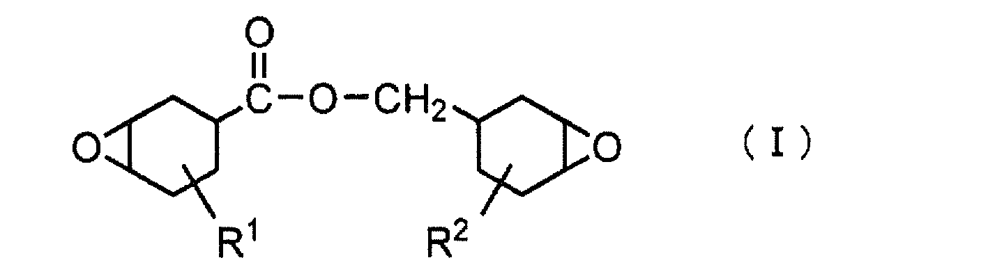
(式中、R1およびR2は、互いに独立して、水素原子または炭素数1~5の直鎖状アルキル基を表す)。
(b)次式(II)で示されるアルカンジオールのエポキシシクロヘキサンカルボキシレート類:
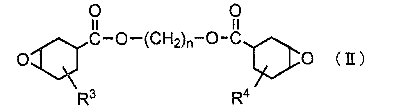
(式中、R3およびR4は、互いに独立して、水素原子または炭素数1~5の直鎖状アルキル基を表し、nは2~20の整数を表す)。
(c)次式(III)で示されるジカルボン酸のエポキシシクロヘキシルメチルエステル類:
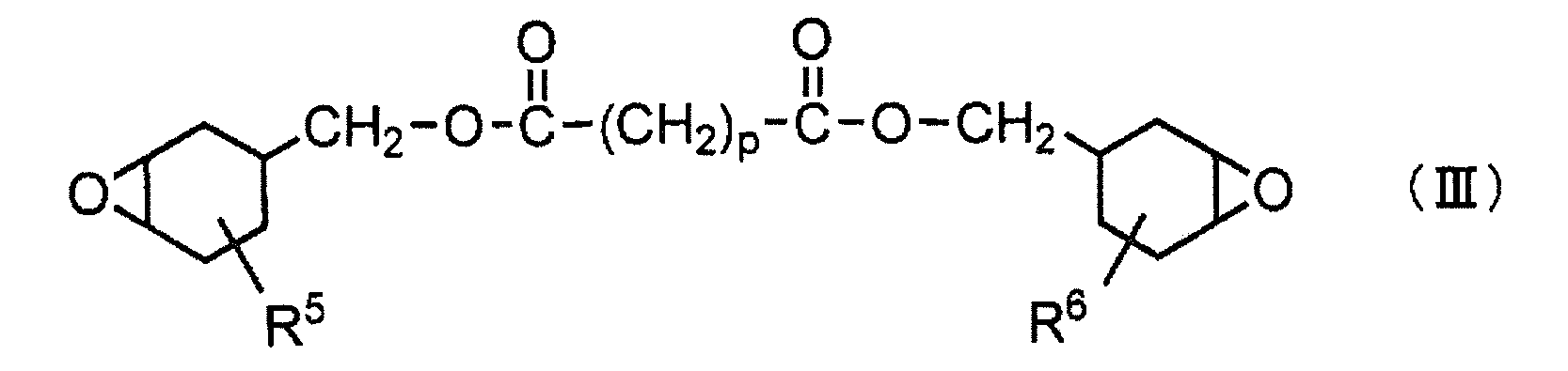
(式中、R5およびR6は、互いに独立して、水素原子または炭素数1~5の直鎖状アルキル基を表し、pは2~20の整数を表す)。
(d)次式(IV)で示されるポリエチレングリコールのエポキシシクロヘキシルメチルエーテル類:

(式中、R7およびR8は、互いに独立して、水素原子または炭素数1~5の直鎖状アルキル基を表し、qは2~10の整数を表す)。
(e)次式(V)で示されるアルカンジオールのエポキシシクロヘキシルメチルエーテル類:

(式中、R9およびR10は、互いに独立して、水素原子または炭素数1~5の直鎖状アルキル基を表し、rは2~20の整数を表す)。
(f)次式(VI)で示されるジエポキシトリスピロ化合物:

(式中、R11およびR12は、互いに独立して、水素原子または炭素数1~5の直鎖状アルキル基を表す)。
(g)次式(VII)で示されるジエポキシモノスピロ化合物:
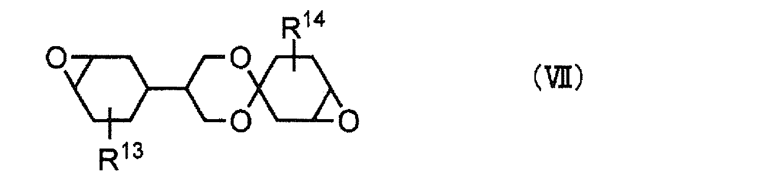
(式中、R13およびR14は、互いに独立して、水素原子または炭素数1~5の直鎖状アルキル基を表す)。
(h)次式(VIII)で示されるビニルシクロヘキセンジエポキシド類:
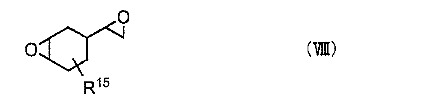
(式中、R15は、水素原子または炭素数1~5の直鎖状アルキル基を表す)。
(i)次式(IX)で示されるエポキシシクロペンチルエーテル類:
(i)次式(IX)で示されるエポキシシクロペンチルエーテル類:

(式中、R16およびR17は、互いに独立して、水素原子または炭素数1~5の直鎖状アルキル基を表す)。
(j)次式(X)で示されるジエポキシトリシクロデカン類:
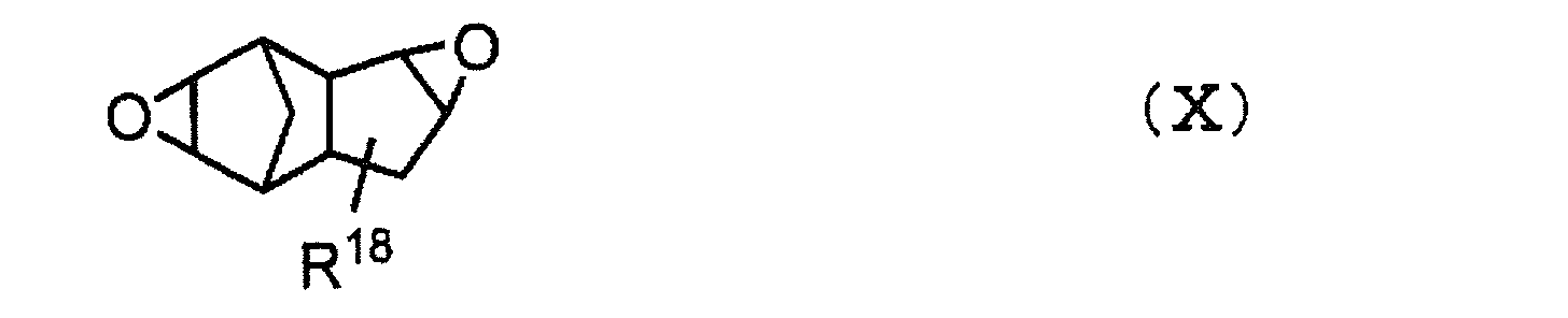
(式中、R18は、水素原子または炭素数1~5の直鎖状アルキル基を表す)。
上記例示した脂環式エポキシ樹脂の中でも、次の脂環式エポキシ樹脂は、市販されているか、またはその類似物であって、入手が比較的容易である等の理由からより好ましく用いられる。
上記例示した脂環式エポキシ樹脂の中でも、次の脂環式エポキシ樹脂は、市販されているか、またはその類似物であって、入手が比較的容易である等の理由からより好ましく用いられる。
(A)7-オキサビシクロ[4.1.0]ヘプタン-3-カルボン酸と(7-オキサ-ビシクロ[4.1.0]ヘプト-3-イル)メタノールとのエステル化物[式(I)において、R1=R2=Hの化合物]、
(B)4-メチル-7-オキサビシクロ[4.1.0]ヘプタン-3-カルボン酸と(4-メチル-7-オキサ-ビシクロ[4.1.0]ヘプト-3-イル)メタノールとのエステル化物[式(I)において、R1=4-CH3、R2=4-CH3の化合物]、
(C)7-オキサビシクロ[4.1.0]ヘプタン-3-カルボン酸と1,2-エタンジオールとのエステル化物[式(II)において、R3=R4=H、n=2の化合物]、
(D)(7-オキサビシクロ[4.1.0]ヘプト-3-イル)メタノールとアジピン酸とのエステル化物[式(III)において、R5=R6=H、p=4の化合物]、
(E)(4-メチル-7-オキサビシクロ[4.1.0]ヘプト-3-イル)メタノールとアジピン酸とのエステル化物[式(III)において、R5=4-CH3、R6=4-CH3、p=4の化合物]、
(F)(7-オキサビシクロ[4.1.0]ヘプト-3-イル)メタノールと1,2-エタンジオールとのエーテル化物[式(V)において、R9=R10=H、r=2の化合物]。
(B)4-メチル-7-オキサビシクロ[4.1.0]ヘプタン-3-カルボン酸と(4-メチル-7-オキサ-ビシクロ[4.1.0]ヘプト-3-イル)メタノールとのエステル化物[式(I)において、R1=4-CH3、R2=4-CH3の化合物]、
(C)7-オキサビシクロ[4.1.0]ヘプタン-3-カルボン酸と1,2-エタンジオールとのエステル化物[式(II)において、R3=R4=H、n=2の化合物]、
(D)(7-オキサビシクロ[4.1.0]ヘプト-3-イル)メタノールとアジピン酸とのエステル化物[式(III)において、R5=R6=H、p=4の化合物]、
(E)(4-メチル-7-オキサビシクロ[4.1.0]ヘプト-3-イル)メタノールとアジピン酸とのエステル化物[式(III)において、R5=4-CH3、R6=4-CH3、p=4の化合物]、
(F)(7-オキサビシクロ[4.1.0]ヘプト-3-イル)メタノールと1,2-エタンジオールとのエーテル化物[式(V)において、R9=R10=H、r=2の化合物]。
また、脂肪族エポキシ樹脂としては、脂肪族多価アルコールまたはそのアルキレンオキサイド付加物のポリグリシジルエーテルを挙げることができる。より具体的には、1,4-ブタンジオールのジグリシジルエーテル;1,6-ヘキサンジオールのジグリシジルエーテル;グリセリンのトリグリシジルエーテル;トリメチロールプロパンのトリグリシジルエーテル;ポリエチレングリコールのジグリシジルエーテル;プロピレングリコールのジグリシジルエーテル;エチレングリコール、プロピレングリコール、およびグリセリン等の脂肪族多価アルコールに1種または2種以上のアルキレンオキサイド(エチレンオキサイドやプロピレンオキサイド)を付加することにより得られるポリエーテルポリオールのポリグリシジルエーテル等が挙げられる。
エポキシ系樹脂組成物からなる接着剤を構成するエポキシ樹脂は、1種のみを単独で使用してもよいし2種以上を併用してもよい。この組成物に用いられるエポキシ樹脂のエポキシ当量は通常、30~3,000g/当量、好ましくは50~1,500g/当量の範囲内である。エポキシ当量が30g/当量を下回ると、硬化後の複合偏光板の可撓性が低下したり、接着強度が低下したりする可能性がある。一方、3,000g/当量を超えると、接着剤に含有される他の成分との相溶性が低下する可能性がある。
この接着剤においては、反応性の観点から、エポキシ樹脂の硬化反応としてカチオン重合が好ましく用いられる。そのために、活性エネルギー線硬化型の接着剤である硬化性エポキシ樹脂組成物には、カチオン重合開始剤を配合することが好ましい。カチオン重合開始剤は、可視光線、紫外線、X線、電子線等の活性エネルギー線の照射によってカチオン種またはルイス酸を発生し、エポキシ基の重合反応を開始させる。以下、活性エネルギー線の照射によりカチオン種またはルイス酸を発生し、エポキシ基の重合反応を開始させるカチオン重合開始剤を「光カチオン重合開始剤」という。
光カチオン重合開始剤を用い、活性エネルギー線の照射により接着剤の硬化を行なう方法は、常温での硬化が可能となり、偏光フィルムの耐熱性または膨張による歪を考慮する必要が減少し、フィルム間を良好に接着できる点において有利である。また、光カチオン重合開始剤は光で触媒的に作用するため、エポキシ樹脂に混合しても保存安定性や作業性に優れる。
光カチオン重合開始剤としては、たとえば、芳香族ジアゾニウム塩;芳香族ヨードニウム塩や芳香族スルホニウム塩等のオニウム塩;鉄-アレン錯体等を挙げることができる。
芳香族ジアゾニウム塩としては、たとえば、ベンゼンジアゾニウム ヘキサフルオロアンチモネート、ベンゼンジアゾニウム ヘキサフルオロホスフェート、ベンゼンジアゾニウム ヘキサフルオロボレート等が挙げられる。また、芳香族ヨードニウム塩としては、たとえば、ジフェニルヨードニウム テトラキス(ペンタフルオロフェニル)ボレート、ジフェニルヨードニウム ヘキサフルオロホスフェート、ジフェニルヨードニウム ヘキサフルオロアンチモネート、ジ(4-ノニルフェニル)ヨードニウム ヘキサフルオロホスフェート等が挙げられる。
芳香族スルホニウム塩としては、たとえば、トリフェニルスルホニウム ヘキサフルオロホスフェート、トリフェニルスルホニウム ヘキサフルオロアンチモネート、トリフェニルスルホニウム テトラキス(ペンタフルオロフェニル)ボレート、4,4’-ビス(ジフェニルスルホニオ)ジフェニルスルフィド ビス(ヘキサフルオロホスフェート)、4,4’-ビス[ジ(β-ヒドロキシエトキシ)フェニルスルホニオ]ジフェニルスルフィド ビス(ヘキサフルオロアンチモネート)、4,4’-ビス[ジ(β-ヒドロキシエトキシ)フェニルスルホニオ]ジフェニルスルフィド ビス(ヘキサフルオロホスフェート)、7-[ジ(p-トルイル)スルホニオ]-2-イソプロピルチオキサントン ヘキサフルオロアンチモネート、7-[ジ(p-トルイル)スルホニオ]-2-イソプロピルチオキサントン テトラキス(ペンタフルオロフェニル)ボレート、4-フェニルカルボニル-4’-ジフェニルスルホニオ-ジフェニルスルフィド ヘキサフルオロホスフェート、4-(p-tert-ブチルフェニルカルボニル)-4’-ジフェニルスルホニオ-ジフェニルスルフィド ヘキサフルオロアンチモネート、4-(p-tert-ブチルフェニルカルボニル)-4’-ジ(p-トルイル)スルホニオ-ジフェニルスルフィド テトラキス(ペンタフルオロフェニル)ボレート等が挙げられる。
また、鉄-アレン錯体としては、たとえば、キシレン-シクロペンタジエニル鉄(II)ヘキサフルオロアンチモネート、クメン-シクロペンタジエニル鉄(II)ヘキサフルオロホスフェート、キシレン-シクロペンタジエニル鉄(II)-トリス(トリフルオロメチルスルホニル)メタナイド等が挙げられる。
これらの光カチオン重合開始剤の市販品は、容易に入手することが可能であり、たとえば、それぞれ商品名で、「カヤラッド PCI-220」および「カヤラッド PCI-620」(以上、日本化薬(株)製)、「UVI-6990」(ユニオンカーバイド社製)、「アデカオプトマー SP-150」および「アデカオプトマー SP-170」(以上、(株)ADEKA製)、「CI-5102」、「CIT-1370」、「CIT-1682」、「CIP-1866S」、「CIP-2048S」および「CIP-2064S」(以上、日本曹達(株)製)、「DPI-101」、「DPI-102」、「DPI-103」、「DPI-105」、「MPI-103」、「MPI-105」、「BBI-101」、「BBI-102」、「BBI-103」、「BBI-105」、「TPS-101」、「TPS-102」、「TPS-103」、「TPS-105」、「MDS-103」、「MDS-105」、「DTS-102」および「DTS-103」(以上、みどり化学(株)製)、「PI-2074」(ローディア社製)等を挙げることができる。
光カチオン重合開始剤は、1種のみを単独で使用してもよいし2種以上を混合して使用してもよい。中でも、芳香族スルホニウム塩は、300nm以上の波長領域でも紫外線吸収特性を有することから、硬化性に優れ、良好な機械的強度や接着強度を有する硬化物を与えることができるため好ましく用いられる。
光カチオン重合開始剤の配合量は、エポキシ樹脂100重量部に対して通常、0.5~20重量部であり、好ましくは1重量部以上、また好ましくは15重量部以下である。光カチオン重合開始剤の配合量が、エポキシ樹脂100重量部に対して0.5重量部を下回ると、硬化が不十分になり、機械的強度や接着強度が低下する傾向にある。また、光カチオン重合開始剤の配合量が、エポキシ樹脂100重量部に対して20重量部を超えると、硬化物中のイオン性物質が増加することで硬化物の吸湿性が高くなり、耐久性能が低下する可能性がある。
光カチオン重合開始剤を用いる場合、硬化性エポキシ樹脂組成物は、必要に応じて、さらに光増感剤を含有することができる。光増感剤を用いることで、カチオン重合の反応性が向上し、硬化物の機械的強度や接着強度を向上させることができる。光増感剤としては、たとえば、カルボニル化合物、有機硫黄化合物、過硫化物、レドックス系化合物、アゾおよびジアゾ化合物、ハロゲン化合物、光還元性色素等が挙げられる。
光増感剤のより具体的な例を挙げれば、たとえば、ベンゾインメチルエーテル、ベンゾインイソプロピルエーテル、およびα,α-ジメトキシ-α-フェニルアセトフェノン等のベンゾイン誘導体;ベンゾフェノン、2,4-ジクロロベンゾフェノン、o-ベンゾイル安息香酸メチル、4,4’-ビス(ジメチルアミノ)ベンゾフェノン、および4,4’-ビス(ジエチルアミノ)ベンゾフェノン等のベンゾフェノン誘導体;2-クロロチオキサントン、および2-イソプロピルチオキサントン等のチオキサントン誘導体;2-クロロアントラキノン、および2-メチルアントラキノン等のアントラキノン誘導体;N-メチルアクリドン、およびN-ブチルアクリドン等のアクリドン誘導体;その他、α,α-ジエトキシアセトフェノン、ベンジル、フルオレノン、キサントン、ウラニル化合物、ハロゲン化合物等がある。光増感剤は、1種のみを単独で使用してもよいし、2種以上を併用してもよい。光増感剤は、硬化性エポキシ樹脂組成物100重量部中、0.1~20重量部の範囲内で含有されることが好ましい。
接着剤に含有されるエポキシ樹脂は、光カチオン重合より硬化されるが、光カチオン重合および熱カチオン重合の双方により硬化してもよい。後者の場合、光カチオン重合開始剤と熱カチオン重合開始剤とを併用することが好ましい。
熱カチオン重合開始剤としては、ベンジルスルホニウム塩、チオフェニウム塩、チオラニウム塩、ベンジルアンモニウム、ピリジニウム塩、ヒドラジニウム塩、カルボン酸エステル、スルホン酸エステル、アミンイミド等を挙げることができる。これらの熱カチオン重合開始剤は、市販品として容易に入手することが可能であり、たとえば、いずれも商品名で、「アデカオプトンCP77」および「アデカオプトンCP66」(以上、株式会社ADEKA製)、「CI-2639」および「CI-2624」(以上、日本曹達株式会社製)、「サンエイドSI-60L」、「サンエイドSI-80L」および「サンエイドSI-100L」(以上、三新化学工業株式会社製)等が挙げられる。
活性エネルギー線硬化型の接着剤は、オキセタン類やポリオール類等、カチオン重合を促進する化合物をさらに含有してもよい。
オキセタン類は、分子内に4員環エーテルを有する化合物であり、たとえば、3-エチル-3-ヒドロキシメチルオキセタン、1,4-ビス[(3-エチル-3-オキセタニル)メトキシメチル]ベンゼン、3-エチル-3-(フェノキシメチル)オキセタン、ジ[(3-エチル-3-オキセタニル)メチル]エーテル、3-エチル-3-(2-エチルヘキシロキシメチル)オキセタン、フェノールノボラックオキセタン等が挙げられる。これらのオキセタン類は、市販品として容易に入手することが可能であり、たとえば、いずれも商品名で、「アロンオキセタン OXT-101」、「アロンオキセタン OXT-121」、「アロンオキセタン OXT-211」、「アロンオキセタン OXT-221」および「アロンオキセタン OXT-212」(以上、東亞合成(株)製)等を挙げることができる。これらのオキセタン類は、硬化性エポキシ樹脂組成物中、通常、5~95重量%、好ましくは30~70重量%の割合で含有される。
ポリオール類としては、フェノール性水酸基以外の酸性基が存在しないものが好ましく、たとえば、水酸基以外の官能基を有しないポリオール化合物、ポリエステルポリオール化合物、ポリカプロラクトンポリオール化合物、フェノール性水酸基を有するポリオール化合物、ポリカーボネートポリオール等を挙げることができる。これらのポリオール類の分子量は通常、48以上、好ましくは62以上、さらに好ましくは100以上、また好ましくは1,000以下である。これらポリオール類は、硬化性エポキシ樹脂組成物中、通常、50重量%以下、好ましくは30重量%以下の割合で含有される。
活性エネルギー線硬化型の接着剤には、さらに、イオントラップ剤、酸化防止剤、連鎖移動剤、粘着付与剤、熱可塑性樹脂、充填剤、流動調整剤、レベリング剤、可塑剤、消泡剤等の添加剤を配合することができる。イオントラップ剤としては粉末状のビスマス系、アンチモン系、マグネシウム系、アルミニウム系、カルシウム系、チタン系およびこれらの混合系等の無機化合物が挙げられ、酸化防止剤としてはヒンダードフェノール系酸化防止剤等が挙げられる。
活性エネルギー線硬化型の接着剤は、溶剤成分を実質的に含まない無溶剤型接着剤として用いることができるが、各塗工方式には各々最適な粘度範囲があるため、粘度調整のために溶剤を含有させてもよい。溶剤としては、偏光フィルムの光学性能を低下させることなく、エポキシ樹脂組成物等を良好に溶解するものを用いることが好ましく、たとえば、トルエンに代表される炭化水素類、酢酸エチルに代表されるエステル類等の有機溶剤を挙げることができる。本発明で用いられる活性エネルギー線硬化型の接着剤の粘度は、例えば5~1000mPa・s程度の範囲であり、好ましくは10~200mPa・sであり、より好ましくは20~100mPa・sである。
(第1の実施形態)
次に図面を参照しながら本発明の偏光板の製造装置および製造方法を説明する。図1は本発明の偏光板の製造装置の第1の実施形態を示す概略図である。
次に図面を参照しながら本発明の偏光板の製造装置および製造方法を説明する。図1は本発明の偏光板の製造装置の第1の実施形態を示す概略図である。
図1に示す偏光板の製造装置では、偏光フィルム1の両面に接着剤を塗布するための接着剤塗工装置11,12と、透明フィルム2,3と偏光フィルム1とを貼合して積層体4を得るための貼合ロール(ニップロール)51,52と、積層体4において透明フィルム2、3と偏光フィルム1とを密着させるためのロール13と、該ロール13の外周面と相対する位置に設置された第1の活性エネルギー線照射装置14,15と、さらにこれより搬送方向下流側に設置された第2以降の活性エネルギー線照射装置16~18と、搬送用ニップロール19とが、搬送方向に沿って順に設けられている。
まず、ロール状に巻回された状態から連続的に繰り出され、不図示の搬送手段により鉛直方向上向きに搬送される偏光フィルム1の両面に、接着剤塗工装置11、12によって活性エネルギー線硬化型の接着剤が塗布される(接着剤塗工工程)。
そして、ロール状に巻回された状態から連続的に繰り出された透明フィルム2,3の両面に、接着剤が塗布された透明フィルム2,3が接着剤を介して積層されてなる積層体を、搬送方向に回転する一対の貼合ロール51,52の間に挟んだ状態で、少なくとも一方の貼合ロールを他方の貼合ロールの方向に押圧することで、透明フィルム1と偏光フィルム2,3とが貼合され、積層体4が形成される(貼合工程)。
次に、この積層体4をロール13の外周面に密着させながら搬送する過程で、第1の活性エネルギー線照射装置14,15からロール13の外周面に向かって活性エネルギー線を照射し、接着剤を重合硬化させる(活性エネルギー線照射工程)。
なお、搬送方向下流側に配置される第2以降の活性エネルギー線照射装置16~18は、接着剤を完全に重合硬化させるための装置であり、必要に応じて追加・省略することができる。最終的に、積層体4は搬送用ニップロール19を通過して、偏光板として巻取ロール20に巻き取られる(偏光板巻取り工程)。以下、各工程について詳細に説明する。
<接着剤塗工工程>
偏光フィルム1への接着剤の塗工方法は特に限定されないが、例えば、ドクターブレード、ワイヤーバー、ダイコーター、カンマコーター、グラビアコーターなど、種々の塗工方式が利用できる。このうち、薄膜塗工、パスラインの自由度、幅広への対応などを考慮すると、接着剤塗工装置11,12としてはグラビアロールが好ましい。
偏光フィルム1への接着剤の塗工方法は特に限定されないが、例えば、ドクターブレード、ワイヤーバー、ダイコーター、カンマコーター、グラビアコーターなど、種々の塗工方式が利用できる。このうち、薄膜塗工、パスラインの自由度、幅広への対応などを考慮すると、接着剤塗工装置11,12としてはグラビアロールが好ましい。
接着剤塗工装置11,12としてグラビアロールを用いて接着剤の塗布を行う場合、塗布された接着剤の厚さ(塗布厚)は、好ましくは0.1~2.0μmであり、より好ましくは0.2μm~1.0μmである。本実施形態においては、偏光フィルム1の表面に直接接着剤を塗布することにより偏光フィルム1表面の凹凸を接着剤により被覆することができるので、透明フィルム2,3との貼合時における気泡の発生を抑制することができる。なお、透明フィルム上に塗布された接着剤を介して透明フィルムと偏光フィルムとを貼合する場合、偏光フィルム表面の凹凸に起因すると解される気泡が発生しやすく、接着剤の塗布厚を厚くすることにより気泡の発生を低減させることができるものの、接着剤の塗布厚が2.0μm以下の場合は、気泡の発生を抑制することが難しい場合がある。本実施形態の接着剤の塗工方法においては、接着剤の厚さが上記範囲内であっても、貼合時の気泡の発生を抑制することができる。
接着剤の塗布厚は、透明フィルムのライン速度に対するグラビアロールの速度比であるドロー比によって調整する。一般的には、ドロー比(グラビアロールの速度/ライン速度)を0.5~10に調整することで、接着剤の塗布厚を0.1~2.0μmに調整することができる。より具体的には、偏光フィルム1のライン速度を10~100m/分とし、グラビアロールを偏光フィルム1の搬送方向と逆方向に回転させ、グラビアロールの速度を5~1000m/分とすることで、接着剤の塗布厚を0.1~2.0μmに調整することができる。
接着剤塗工工程においては、上述のように偏光フィルム1の搬送方向を鉛直方向上向きとし、接着剤塗工装置11,12により偏光フィルム1の両側から接着剤を塗布する。水平方向に搬送される偏光フィルムに対しては、下方から接着剤を塗布することはできるものの、通常の塗工装置により上方から連続的に塗布することは接着剤が垂れ落ちるので難しい。したがって、偏光フィルム1の両面に透明フィルムを貼合する偏光板の製造方法の場合、本実施形態の装置のように鉛直方向上向きに搬送される偏光フィルム1に対して両側から接着剤を塗布する方法が有用である。本明細書における「鉛直方向上向き」とは、両側面からの接着剤の塗布が可能であれば鉛直方向のみに限定されることはなく、たとえば鉛直方向上向きに対して±5度の範囲内の方向を含むものとする。
搬送される偏光フィルム1の両側に配置される接着剤塗工装置11,12は、両者が対向しない位置に配置されることが好ましい。接着剤の塗布厚さは、接着剤塗工装置11,12の押圧により偏光フィルム1に加えられる圧力によっても調整可能であるが、対向する位置に配置されると、圧力を調整することが難しくなるからである。
接着剤は、調製後、通常は15~40℃の範囲内の所定温度±5℃(例えば、所定温度が30℃である場合、30℃±5℃)、好ましくは±3℃、より好ましくは±1℃に調整された環境下で塗布される。
<貼合工程>
本工程では、上記工程により接着剤が塗布された偏光フィルム1の両面に、ロール状に巻回された状態から連続的に繰り出された透明フィルム2,3が接着剤を介して積層される。この積層体を、搬送方向に回転する一対の貼合ロール51,52の間に挟んだ状態で、例えば貼合ロール51を貼合ロール52の方向に押圧することで、透明フィルム1と偏光フィルム2,3とが貼合され、積層体4が形成される。
本工程では、上記工程により接着剤が塗布された偏光フィルム1の両面に、ロール状に巻回された状態から連続的に繰り出された透明フィルム2,3が接着剤を介して積層される。この積層体を、搬送方向に回転する一対の貼合ロール51,52の間に挟んだ状態で、例えば貼合ロール51を貼合ロール52の方向に押圧することで、透明フィルム1と偏光フィルム2,3とが貼合され、積層体4が形成される。
押圧により積層体に加えられる圧力は、特に限定されないが、金属製ロールとゴム製ロールとを用いる場合は、富士フイルム製ツーシートタイププレスケースにおける瞬間圧が0.2~3.0MPaであることが好ましく、より好ましくは0.5~2.3MPaである。
一対の貼合ロールは、一方の貼合ロールともう一方の貼合ロールの周速度に差があってもよい。たとえば、積層体4の液晶パネルに貼合される面側に設置された貼合ロール(第1の貼合ロール)の周速度が、反対側の貼合ロール(第2の貼合ロール)の周速度よりも速いことが好ましい。これにより、得られる偏光板に、液晶パネルに貼合される面が凸になり、その反対側の面が凹になるようなカール(正カール)を与えることができる。得られる偏光板に、液晶パネルに貼合される面が凹になり、その反対側の面が凸になるようなカール(逆カール)が付与された場合は、偏光板を液晶セルに貼合するときに、中央部に気泡を噛み込むなどの不具合が生じやすくなってしまう。なお、この場合、第1の貼合ロールとして金属製ロールを使用し、第2の貼合ロールとしてゴム製ロールを使用することが好ましい。
さらに、第2の貼合ロールの周速度を1としたとき、第1の貼合ロールの周速度の比が1.0050~1.0200であることがより好ましい。この範囲より第1の貼合ロールの周速度が速い場合は、正カールのカール量が大きくなりすぎ、偏光板を液晶セルに貼合するときに端部に気泡を噛み込むなどの不具合が生じやすく、さらには過酷な環境下に置かれた場合に正カールがさらに助長されて偏光板の端部が液晶セルから剥れる恐れがあるからである。
<活性エネルギー線照射工程>
ロール13は、外周面が鏡面仕上げされた凸曲面を構成しており、その表面に積層体4を密着させながら搬送し、その過程で活性エネルギー線照射装置14,15により接着剤を重合硬化させる。接着剤を重合硬化させ、積層体4を充分に密着させる上で、ロール13の直径は特に限定されない。ロール13は、積層体4のラインの動きに従動または回転駆動させてもよく、あるいは固定させて表面を積層体4が滑るようにしてもよい。また、ロール13は、活性エネルギー線の照射による重合硬化時に、積層体4に生じる熱を放熱させるための冷却ロールとして作用させてもよい。その場合、冷却ロールの表面温度は、20~30℃に設定されることが好ましい。
ロール13は、外周面が鏡面仕上げされた凸曲面を構成しており、その表面に積層体4を密着させながら搬送し、その過程で活性エネルギー線照射装置14,15により接着剤を重合硬化させる。接着剤を重合硬化させ、積層体4を充分に密着させる上で、ロール13の直径は特に限定されない。ロール13は、積層体4のラインの動きに従動または回転駆動させてもよく、あるいは固定させて表面を積層体4が滑るようにしてもよい。また、ロール13は、活性エネルギー線の照射による重合硬化時に、積層体4に生じる熱を放熱させるための冷却ロールとして作用させてもよい。その場合、冷却ロールの表面温度は、20~30℃に設定されることが好ましい。
活性エネルギー線の照射により接着剤の重合硬化を行うために用いる光源は、特に限定されないが、波長400nm以下に発光分布を有する光源であることが好ましい。このような光源としては、例えば、低圧水銀灯、中圧水銀灯、高圧水銀灯、超高圧水銀灯、ケミカルランプ、ブラックライトランプ、マイクロウェーブ励起水銀灯、メタルハライドランプが挙げられる。
活性エネルギー線硬化型接着剤への光照射強度は、接着剤の組成ごとに決定されるものであって特に限定されないが、10~5000mW/cm2であることが好ましい。樹脂組成物への光照射強度が10mW/cm2未満であると、反応時間が長くなりすぎ、5000mW/cm2を超えると、ランプから輻射される熱および組成物の重合時の発熱により、接着剤の構成材料であるエポキシ樹脂組成物などの黄変や偏光フィルムの劣化を生じる可能性がある。なお、照射強度は、好ましくは光カチオン重合開始剤の活性化に有効な波長領域における強度であり、より好ましくは波長400nm以下の波長領域における強度であり、さらに好ましくは波長280~320nmの波長領域における強度である。
活性エネルギー線硬化型接着剤への活性エネルギー線の照射時間は、硬化する組成物毎に制御されるものであって、特に限定されないが、照射強度と照射時間の積として表される積算光量が10mJ/cm2以上、好ましくは10~5,000mJ/cm2となるように設定されることが好ましい。上記接着剤への積算光量が10mJ/cm2未満であると、開始剤由来の活性種の発生が十分でなく、接着剤の硬化が不十分となる。一方でその積算光量が5,000mJ/cm2を超えると、照射時間が非常に長くなり、生産性向上には不利なものとなる。
本発明においては、積層体に活性エネルギー線を照射して接着剤を重合硬化させるが、加熱による重合硬化を併用してもよい。
活性エネルギー線が紫外線である場合、積層体4に活性エネルギー線を照射する工程では、積層体4に長手方向(搬送方向)に100~800N/mの張力をかけながら、照射時間が0.1秒以上となるようなライン速度で積層体4が搬送されることが好ましい。また、紫外線の照射強度は10mW/cm2以上とすることが好ましい。
また、活性エネルギー線照射装置14,15による活性エネルギー線の積算光量が不十分な場合は、さらに第2以降の活性エネルギー線照射装置16~18を設け、活性エネルギー線を追加照射させ、積層体4の接着剤の硬化を促進することが好ましい。これらの全工程における積算光量が10mJ/cm2以上、好ましくは10~5,000mJ/cm2となるように設定されることが好ましい。このように、活性エネルギー線を照射する工程においては、活性エネルギー線の照射は複数回に分けて行われることが好ましい。
偏光板(積層体)端部の接着剤の硬化を確実に行うためには、例えば、無電極DバルブランプであるFUSION製「Light Hammer 10」をフィルム走行に対して横断するように並べる方法などが挙げられる。
活性エネルギー線硬化型樹脂が硬化した割合、即ち反応率は、好ましくは90%以上、より好ましくは95%以上である。
<偏光板巻取り工程>
積層体(偏光板)4を巻き取る張力を30N/cm2~150N/cm2とする。好ましくは、30N/cm2~120N/cm2である。30N/cm2未満では長尺のロール巻きを移送する際、巻きズレが起きるため好ましくない。150N/cm2より大きい場合は、巻き締まりが強く、タルミが発生し易い。
積層体(偏光板)4を巻き取る張力を30N/cm2~150N/cm2とする。好ましくは、30N/cm2~120N/cm2である。30N/cm2未満では長尺のロール巻きを移送する際、巻きズレが起きるため好ましくない。150N/cm2より大きい場合は、巻き締まりが強く、タルミが発生し易い。
なお、巻き長さが長くなるほど、同一張力では巻き締まり(繰り出した際に平坦な状態に戻り難くなる現象)が起き易くなるため、偏光板をコアに巻きながら張力を連続的または段階的に低下させてもよい。このような所謂テーパーをかけて張力を下げる方法においても、その際の張力は150N/cm2以下とする。
コアに巻き取られる偏光板の長さは、特に限定されないが、好ましくは100m以上4000m以下である。
円筒状のコアの直径は、6インチ~12インチが好ましい。コアの直径は大きいほど好ましく、11インチ、12インチなどより好ましいが、さらに大きすぎると移送や保管が難しくなる。
円筒状コアの材質は、クリーンルームで使用するため、それ自身が発塵し難く、広い幅の偏光板を巻き取れるように適切な強度が確保できれば特に限定はないが、FRP(ガラス繊維強化プラスチック)などを選択できる。
(第2の実施形態)
図2は本発明の偏光板の製造装置の第2の実施形態を示す概略図である。第2の実施形態の製造装置は、ロール状に巻回された状態から連続的に繰り出される偏光フィルム1が、不図示の搬送手段により鉛直方向下向きに搬送される点で、鉛直方向上向きに搬送される第1の実施形態と異なる。他の構成については、第1の実施形態と同様であるので説明を省略する。なお、本明細書における「鉛直方向下向き」とは、両側面からの接着剤の塗布が可能であれば鉛直方向のみに限定されることはなく、たとえば鉛直方向下向きに対して±5度の範囲内の方向を含むものとする。
図2は本発明の偏光板の製造装置の第2の実施形態を示す概略図である。第2の実施形態の製造装置は、ロール状に巻回された状態から連続的に繰り出される偏光フィルム1が、不図示の搬送手段により鉛直方向下向きに搬送される点で、鉛直方向上向きに搬送される第1の実施形態と異なる。他の構成については、第1の実施形態と同様であるので説明を省略する。なお、本明細書における「鉛直方向下向き」とは、両側面からの接着剤の塗布が可能であれば鉛直方向のみに限定されることはなく、たとえば鉛直方向下向きに対して±5度の範囲内の方向を含むものとする。
本実施形態の製造装置においても、第1の実施形態と同様に、偏光フィルム1の両側から接着剤を塗布することができるので、偏光フィルム1の両面に透明フィルム2,3を貼合する偏光板の製造方法に有用である。本実施形態においては、偏光フィルム1の表面に直接接着剤を塗布することにより偏光フィルム1表面の凹凸を接着剤により被覆することができるので、透明フィルム2,3との貼合時における気泡の発生を抑制することができる。
(第3の実施形態)
図3は本発明の偏光板の製造装置の第3の実施形態を示す概略図である。第3の実施形態の製造装置においては、ロールに積層体を密着させた状態での活性エネルギー線の照射はなされず、したがって図1におけるロール13、活性エネルギー線照射装置14,15を備えない点のみ、第1の実施形態の製造装置と異なる。本実施形態の製造装置においては、図1における第1の活性エネルギー線照射装置14,15の代わりに、活性エネルギー線照射装置16,17,18により積層体4に活性エネルギー線を照射し、接着剤を重合硬化させる。活性エネルギー線照射工程における、光照射強度、積算光量等の好ましい各条件は、第1の実施形態における活性エネルギー線照射工程における好ましい各条件と同様である。他の構成および他の工程は、第1の実施形態と同様であるので説明を省略する。
図3は本発明の偏光板の製造装置の第3の実施形態を示す概略図である。第3の実施形態の製造装置においては、ロールに積層体を密着させた状態での活性エネルギー線の照射はなされず、したがって図1におけるロール13、活性エネルギー線照射装置14,15を備えない点のみ、第1の実施形態の製造装置と異なる。本実施形態の製造装置においては、図1における第1の活性エネルギー線照射装置14,15の代わりに、活性エネルギー線照射装置16,17,18により積層体4に活性エネルギー線を照射し、接着剤を重合硬化させる。活性エネルギー線照射工程における、光照射強度、積算光量等の好ましい各条件は、第1の実施形態における活性エネルギー線照射工程における好ましい各条件と同様である。他の構成および他の工程は、第1の実施形態と同様であるので説明を省略する。
本実施形態の製造装置においても、第1の実施形態と同様に、偏光フィルム1の両側から接着剤を塗布することができるので、偏光フィルム1の両面に透明フィルム2,3を貼合する偏光板の製造方法に有用である。本実施形態においては、偏光フィルム1の表面に直接接着剤を塗布することにより偏光フィルム1表面の凹凸を接着剤により被覆することができるので、透明フィルム2,3との貼合時における気泡の発生を抑制することができる。
(第4の実施形態)
本実施形態において、偏光板は、1枚の偏光フィルムおよび1枚の透明フィルムから製造される。そして、接着剤塗工工程において、1枚の偏光フィルムの片面に接着剤を塗工し、貼合工程において、偏光フィルムおよび透明フィルムを、透明フィルムの片面に偏光フィルムの接着剤が接するように積層した状態で、一対の貼合ロールの間に挟むことで、偏光フィルムおよび透明フィルムを互いに貼合する。
本実施形態において、偏光板は、1枚の偏光フィルムおよび1枚の透明フィルムから製造される。そして、接着剤塗工工程において、1枚の偏光フィルムの片面に接着剤を塗工し、貼合工程において、偏光フィルムおよび透明フィルムを、透明フィルムの片面に偏光フィルムの接着剤が接するように積層した状態で、一対の貼合ロールの間に挟むことで、偏光フィルムおよび透明フィルムを互いに貼合する。
次に、図面を参照しながら本実施形態の製造方法について説明する。図4は、本発明の偏光板の製造装置の第4の実施形態を示す概略図である。
図4に示す偏光板の製造装置では、偏光フィルム1の片面に接着剤を塗布するための接着剤塗工装置11と、偏光フィルム1と透明フィルム2とを貼合して積層体4を得るための貼合ロール(ニップロール)51,52と、積層体4において偏光フィルム1と透明フィルム2とを密着させるためのロール13と、該ロール13の外周面と相対する位置に設置された第1の活性エネルギー線照射装置14,15と、さらにこれより搬送方向下流側に設置された第2以降の活性エネルギー線照射装置16~18と、搬送用ニップロール19とが、搬送方向に沿って順に設けられている。
まず、ロール状に巻回された状態から連続的に繰り出される偏光フィルム1の片面に、接着剤塗工装置11によって活性エネルギー線硬化型の接着剤が塗布される(接着剤塗工工程)。
そして、ロール状に巻回された状態から連続的に繰り出された透明フィルム2の片面に、接着剤が塗布された偏光フィルム1が接着剤を介して積層されてなる積層体を、搬送方向に回転する一対の貼合ロール51,52の間に挟んだ状態で、少なくとも一方の貼合ロールを他方の貼合ロールの方向に押圧することで、偏光フィルム2と透明フィルム1とが貼合され、積層体4が形成される(貼合工程)。
次に、この積層体4をロール13の外周面に密着させながら搬送する過程で、第1の活性エネルギー線照射装置14,15からロール13の外周面に向かって活性エネルギー線を照射し、接着剤を重合硬化させる(活性エネルギー線照射工程)。なお、搬送方向下流側に配置される第2以降の活性エネルギー線照射装置16~18は、接着剤を完全に重合硬化させるための装置であり、必要に応じて追加・省略することができる。各工程の詳細については、実施形態1と同様であるため省略する。
本実施形態の製造装置においては、偏光フィルム1の片側から接着剤を塗布することができるので、偏光フィルムの片面に透明フィルムを貼合する偏光板の製造方法に有用である。本実施形態においては、偏光フィルムの表面に直接接着剤を塗布することにより偏光フィルム表面の凹凸を接着剤により被覆することができるので、透明フィルム2の貼合時における気泡の発生を抑制することができる。
以下に実施例を挙げて、本発明をさらに詳しく説明するが、本発明はこれら実施例に限定されるものではない。
[実施例1]
本実施例では、上記第4の実施形態で説明した図4に示すような装置を用いて、1枚の偏光フィルムと1枚の透明フィルムを貼合してなる偏光板を作製した。
本実施例では、上記第4の実施形態で説明した図4に示すような装置を用いて、1枚の偏光フィルムと1枚の透明フィルムを貼合してなる偏光板を作製した。
厚さ40μmのトリアセチルセルロースフィルム「KC4CR-1」(コニカミノルタ社製)と、偏光フィルムが最表面にある厚さ135μmの複合フィルム積層体(ポリビニルアルコールフィルム「ビニロンVF-PS#7500」(クラレ製)よりなる偏光フィルムとセルロースエステル系樹脂フィルム「KC4UYW」(コニカミノルタオプト(株)製)およびKC4UYW面に粘着剤層付き表面保護フィルム「NBO-0424」(藤森工業(株)製)がこの順に積層されたもの)とを準備し、複合フィルム積層体の偏光フィルムの表面に、紫外線硬化型の接着剤であるエポキシ樹脂組成物「KR-70T」(ADEKA社製、粘度:44mPa・s)を接着剤塗工装置を用いて図4等に示すように鉛直方向上向きに該フィルムを搬送しながら塗工した。この際、接着剤塗工装置における偏光フィルム積層体のライン速度を25m/分とし、グラビアロールを積層材の搬送方向と逆方向に回転させ、接着剤層の厚みを1.0μmとした。
次に、トリアセチルセルロースフィルムが偏光フィルムに塗工された接着剤と接するように積層された積層体を、共に直径250mmの一対のニップロール(貼合ロール)に挟み、1.0MPaの圧力で押し付けることで、上記トリアセチルセルロースフィルムと上記偏光フィルムとを貼り合わせた。
上記2種のフィルムが貼合された積層体を、長手方向に600N/mの張力を掛けながらライン速度25m/分で移送し、総積算光量(波長280~320nmの波長領域における光照射強度の積算量)が約250mJ/cm2(測定器:FusionUV社製UV Power PuckIIによる測定値)の紫外線(UVB)を照射した。
得られた偏光板について目視で観察したところ、偏光フィルムとトリアセチルセルロースフィルムとの間に気泡は観察されなかった。
[比較例1]
紫外線硬化型の接着剤であるエポキシ樹脂組成物を、トリアセチルセルロースフィルムの片面に厚さ1.0μmとなるように接着剤塗工装置を用いて塗工し、塗工した接着剤を介して複合フィルム積層体の偏光フィルムに貼合した点以外は、実施例1と同様にして偏光板を作製した。
紫外線硬化型の接着剤であるエポキシ樹脂組成物を、トリアセチルセルロースフィルムの片面に厚さ1.0μmとなるように接着剤塗工装置を用いて塗工し、塗工した接着剤を介して複合フィルム積層体の偏光フィルムに貼合した点以外は、実施例1と同様にして偏光板を作製した。
得られた偏光板について目視で観察したところ、偏光フィルムとトリアセチルセルロースフィルムとの間に気泡が観察された。
本発明の偏光板は、液晶表示装置をはじめとする各種表示装置に有効に適用することができる。
1 偏光フィルム、2,3 透明フィルム、4 積層体(偏光板)、11,12 接着剤塗工装置、13 ロール(冷却ロール)、14,15,16,17,18 活性エネルギー線照射装置、19 搬送用ニップロール、20 巻取ロール、51,52 貼合ロール。
Claims (6)
- 偏光フィルムの片面または両面に透明フィルムが貼合されてなる偏光板の製造方法であって、
前記偏光フィルムの片面または両面に、活性エネルギー線硬化型の接着剤を塗布する接着剤塗工工程と、
前記透明フィルムが前記偏光フィルムの片面または両面に前記接着剤を介して積層されてなる積層体を、搬送方向に回転する一対の貼合ロールの間に挟んで押圧することで、前記透明フィルムと前記偏光フィルムとを貼合する貼合工程と、
前記積層体に活性エネルギー線を照射して前記接着剤を硬化させる活性エネルギー線照射工程とを備える、偏光板の製造方法。 - 前記接着剤塗工工程において、前記偏光フィルムの片面または両面に塗布される活性エネルギー線硬化型の接着剤の塗布厚は、0.1~2.0μmである、請求項1に記載の偏光板の製造方法。
- 前記接着剤塗工工程は、鉛直方向上向きに搬送される前記偏光フィルムの片面または両面に、活性エネルギー線硬化型の接着剤を塗布する工程である、請求項1または2に記載の偏光板の製造方法。
- 前記接着剤塗工工程は、鉛直方向下向きに搬送される前記偏光フィルムの片面または両面に、活性エネルギー線硬化型の接着剤を塗布する工程である、請求項1または2に記載の偏光板の製造方法。
- 偏光フィルムの片面または両面に透明フィルムが貼合されてなる偏光板の製造装置であって、
鉛直方向上向きに前記偏光フィルムを搬送する搬送手段と、
鉛直方向上向きに搬送されている前記偏光フィルムの片面または両面に、活性エネルギー線硬化型の接着剤を塗布するための接着剤塗工装置と、
前記透明フィルムが前記偏光フィルムの片面または両面に前記接着剤を介して積層されてなる積層体を、搬送しながら挟圧することにより、前記透明フィルムと前記偏光フィルムとを貼合するための一対の貼合ロールと、
前記積層体に活性エネルギー線を照射して前記接着剤を硬化させるための活性エネルギー線照射装置と、を備える、偏光板の製造装置。 - 偏光フィルムの片面または両面に透明フィルムが貼合されてなる偏光板の製造装置であって、
鉛直方向下向きに前記偏光フィルムを搬送する搬送手段と、
鉛直方向下向きに搬送されている前記偏光フィルムの片面または両面に、活性エネルギー線硬化型の接着剤を塗布するための接着剤塗工装置と、
前記透明フィルムが前記偏光フィルムの片面または両面に前記接着剤を介して積層されてなる積層体を、搬送しながら挟圧することにより、前記透明フィルムと前記偏光フィルムとを貼合するための一対の貼合ロールと、
前記積層体に活性エネルギー線を照射して前記接着剤を硬化させるための活性エネルギー線照射装置と、を備える、偏光板の製造装置。
Priority Applications (3)
| Application Number | Priority Date | Filing Date | Title |
|---|---|---|---|
| KR1020147031624A KR102243122B1 (ko) | 2012-07-02 | 2013-06-28 | 편광판의 제조 방법 및 제조 장치 |
| CN201380034231.8A CN104395786B (zh) | 2012-07-02 | 2013-06-28 | 偏振板的制造方法及制造装置 |
| KR1020217010216A KR102475633B1 (ko) | 2012-07-02 | 2013-06-28 | 편광판의 제조 방법 및 제조 장치 |
Applications Claiming Priority (2)
| Application Number | Priority Date | Filing Date | Title |
|---|---|---|---|
| JP2012148375A JP6371031B2 (ja) | 2012-07-02 | 2012-07-02 | 偏光板の製造方法および製造装置 |
| JP2012-148375 | 2012-07-02 |
Publications (1)
| Publication Number | Publication Date |
|---|---|
| WO2014007160A1 true WO2014007160A1 (ja) | 2014-01-09 |
Family
ID=49881916
Family Applications (1)
| Application Number | Title | Priority Date | Filing Date |
|---|---|---|---|
| PCT/JP2013/067806 Ceased WO2014007160A1 (ja) | 2012-07-02 | 2013-06-28 | 偏光板の製造方法および製造装置 |
Country Status (5)
| Country | Link |
|---|---|
| JP (1) | JP6371031B2 (ja) |
| KR (2) | KR102243122B1 (ja) |
| CN (2) | CN107340560A (ja) |
| TW (2) | TWI570458B (ja) |
| WO (1) | WO2014007160A1 (ja) |
Cited By (4)
| Publication number | Priority date | Publication date | Assignee | Title |
|---|---|---|---|---|
| JPS58108988A (ja) * | 1981-11-18 | 1983-06-29 | ゼネラル・エレクトリツク・カンパニイ | 金属圧延機の急激な荷重変化による速度補償方法及び装置 |
| JP2014048496A (ja) * | 2012-08-31 | 2014-03-17 | Nitto Denko Corp | 偏光フィルムの製造方法 |
| JP2018028669A (ja) * | 2017-09-27 | 2018-02-22 | 日東電工株式会社 | 偏光フィルムの製造方法 |
| JP2019023759A (ja) * | 2018-11-12 | 2019-02-14 | 日東電工株式会社 | 偏光フィルムの製造方法 |
Families Citing this family (10)
| Publication number | Priority date | Publication date | Assignee | Title |
|---|---|---|---|---|
| JP6371031B2 (ja) * | 2012-07-02 | 2018-08-08 | 住友化学株式会社 | 偏光板の製造方法および製造装置 |
| JP2017058664A (ja) * | 2015-09-14 | 2017-03-23 | 住友化学株式会社 | 積層光学フィルムの製造方法、及び、積層光学フィルムの製造装置 |
| KR102512665B1 (ko) * | 2016-08-18 | 2023-03-21 | 스미또모 가가꾸 가부시키가이샤 | 편광 필름의 제조 방법 및 제조 장치 |
| JP6622347B2 (ja) * | 2018-04-06 | 2019-12-18 | 住友化学株式会社 | 偏光板の製造方法および製造装置 |
| JP7463050B2 (ja) * | 2018-06-05 | 2024-04-08 | 日東電工株式会社 | 偏光フィルムロールの製造方法 |
| JP6947870B2 (ja) * | 2018-11-12 | 2021-10-13 | 日東電工株式会社 | 偏光フィルムの製造方法 |
| KR102325975B1 (ko) * | 2019-01-08 | 2021-11-12 | 주식회사 엘지화학 | 광학 적층체, 편광판, 및 디스플레이 장치 |
| JP7224729B2 (ja) * | 2019-04-25 | 2023-02-20 | 日東電工株式会社 | 積層偏光フィルムの製造方法及び積層偏光フィルムの製造装置 |
| JP7305473B2 (ja) * | 2019-07-18 | 2023-07-10 | 日東電工株式会社 | 偏光フィルムの製造方法及び偏光フィルムの製造装置 |
| JP2024049134A (ja) * | 2022-09-28 | 2024-04-09 | 日本ゼオン株式会社 | 光学フィルムの製造方法 |
Citations (6)
| Publication number | Priority date | Publication date | Assignee | Title |
|---|---|---|---|---|
| JP2008276136A (ja) * | 2007-05-07 | 2008-11-13 | Kyoritsu Kagaku Sangyo Kk | フィルム接着装置及び偏光板製造装置 |
| JP2009134190A (ja) * | 2007-11-30 | 2009-06-18 | Sumitomo Chemical Co Ltd | 偏光板の製造方法 |
| JP2010018722A (ja) * | 2008-07-11 | 2010-01-28 | Fujicopian Co Ltd | 光硬化型接着剤組成物及びそれを用いた偏光板 |
| JP2010018721A (ja) * | 2008-07-11 | 2010-01-28 | Fujicopian Co Ltd | 光硬化型接着剤組成物及びそれを用いた偏光板 |
| JP2011186481A (ja) * | 2007-04-16 | 2011-09-22 | Nitto Denko Corp | 偏光板、光学フィルムおよび画像表示装置 |
| JP2011197617A (ja) * | 2010-03-24 | 2011-10-06 | Sumitomo Chemical Co Ltd | 偏光板 |
Family Cites Families (20)
| Publication number | Priority date | Publication date | Assignee | Title |
|---|---|---|---|---|
| JP3184792B2 (ja) * | 1997-12-22 | 2001-07-09 | 日本合成化学工業株式会社 | 光学積層体の製法 |
| JP4306270B2 (ja) * | 2003-02-12 | 2009-07-29 | 住友化学株式会社 | 偏光板、その製造法、光学部材及び液晶表示装置 |
| JP5013496B2 (ja) * | 2005-01-20 | 2012-08-29 | 日東電工株式会社 | 偏光板、偏光板の製造方法、光学フィルムおよび画像表示装置 |
| JP4971022B2 (ja) * | 2006-07-12 | 2012-07-11 | 日東電工株式会社 | 多層積層フィルムの製造方法 |
| JP5090695B2 (ja) * | 2006-09-08 | 2012-12-05 | 大倉工業株式会社 | 偏光板の製造方法 |
| JP4335901B2 (ja) * | 2006-11-14 | 2009-09-30 | 日東電工株式会社 | 偏光板の製造方法 |
| JP4758327B2 (ja) * | 2006-11-28 | 2011-08-24 | 協立化学産業株式会社 | 偏光板 |
| JP5022043B2 (ja) * | 2007-01-19 | 2012-09-12 | 大倉工業株式会社 | 活性エネルギー線硬化型接着剤組成物及びそれを用いた偏光板 |
| US8722182B2 (en) * | 2007-04-16 | 2014-05-13 | Nitto Denko Corporation | Polarizing plate, optical film and image display |
| TWI541569B (zh) * | 2008-03-31 | 2016-07-11 | 住友化學股份有限公司 | 偏光板的製造裝置及製造方法 |
| JP2010191203A (ja) * | 2009-02-18 | 2010-09-02 | Sumitomo Chemical Co Ltd | 偏光板の製造方法 |
| JP5407527B2 (ja) * | 2009-04-28 | 2014-02-05 | 住友化学株式会社 | 光学表示パネルの製造方法 |
| JP4561936B1 (ja) * | 2009-09-04 | 2010-10-13 | 東洋インキ製造株式会社 | 偏光板及び偏光板形成用光硬化性接着剤 |
| JP5446732B2 (ja) | 2009-10-30 | 2014-03-19 | 住友化学株式会社 | 偏光板の製造方法 |
| JP5446933B2 (ja) * | 2010-01-28 | 2014-03-19 | 住友化学株式会社 | 偏光板の製造方法 |
| JP5495906B2 (ja) * | 2010-04-06 | 2014-05-21 | 東亞合成株式会社 | 光硬化性接着剤組成物、偏光板とその製造法、光学部材及び液晶表示装置 |
| KR20110131512A (ko) * | 2010-05-31 | 2011-12-07 | 동우 화인켐 주식회사 | 편광판 및 이의 제조방법 |
| KR101279612B1 (ko) * | 2010-08-13 | 2013-06-28 | 주식회사 엘지화학 | 편광판 및 이를 포함하는 액정 표시 장치 |
| JP5991803B2 (ja) * | 2010-10-29 | 2016-09-14 | 住友化学株式会社 | 偏光板の製造方法 |
| JP6371031B2 (ja) * | 2012-07-02 | 2018-08-08 | 住友化学株式会社 | 偏光板の製造方法および製造装置 |
-
2012
- 2012-07-02 JP JP2012148375A patent/JP6371031B2/ja active Active
-
2013
- 2013-06-28 KR KR1020147031624A patent/KR102243122B1/ko active Active
- 2013-06-28 CN CN201710685644.2A patent/CN107340560A/zh active Pending
- 2013-06-28 KR KR1020217010216A patent/KR102475633B1/ko active Active
- 2013-06-28 WO PCT/JP2013/067806 patent/WO2014007160A1/ja not_active Ceased
- 2013-06-28 CN CN201380034231.8A patent/CN104395786B/zh active Active
- 2013-07-01 TW TW102123435A patent/TWI570458B/zh active
- 2013-07-01 TW TW105143549A patent/TWI613472B/zh active
Patent Citations (6)
| Publication number | Priority date | Publication date | Assignee | Title |
|---|---|---|---|---|
| JP2011186481A (ja) * | 2007-04-16 | 2011-09-22 | Nitto Denko Corp | 偏光板、光学フィルムおよび画像表示装置 |
| JP2008276136A (ja) * | 2007-05-07 | 2008-11-13 | Kyoritsu Kagaku Sangyo Kk | フィルム接着装置及び偏光板製造装置 |
| JP2009134190A (ja) * | 2007-11-30 | 2009-06-18 | Sumitomo Chemical Co Ltd | 偏光板の製造方法 |
| JP2010018722A (ja) * | 2008-07-11 | 2010-01-28 | Fujicopian Co Ltd | 光硬化型接着剤組成物及びそれを用いた偏光板 |
| JP2010018721A (ja) * | 2008-07-11 | 2010-01-28 | Fujicopian Co Ltd | 光硬化型接着剤組成物及びそれを用いた偏光板 |
| JP2011197617A (ja) * | 2010-03-24 | 2011-10-06 | Sumitomo Chemical Co Ltd | 偏光板 |
Cited By (4)
| Publication number | Priority date | Publication date | Assignee | Title |
|---|---|---|---|---|
| JPS58108988A (ja) * | 1981-11-18 | 1983-06-29 | ゼネラル・エレクトリツク・カンパニイ | 金属圧延機の急激な荷重変化による速度補償方法及び装置 |
| JP2014048496A (ja) * | 2012-08-31 | 2014-03-17 | Nitto Denko Corp | 偏光フィルムの製造方法 |
| JP2018028669A (ja) * | 2017-09-27 | 2018-02-22 | 日東電工株式会社 | 偏光フィルムの製造方法 |
| JP2019023759A (ja) * | 2018-11-12 | 2019-02-14 | 日東電工株式会社 | 偏光フィルムの製造方法 |
Also Published As
| Publication number | Publication date |
|---|---|
| TWI570458B (zh) | 2017-02-11 |
| CN104395786B (zh) | 2017-09-01 |
| JP6371031B2 (ja) | 2018-08-08 |
| KR20150035528A (ko) | 2015-04-06 |
| JP2014010385A (ja) | 2014-01-20 |
| CN104395786A (zh) | 2015-03-04 |
| KR102475633B1 (ko) | 2022-12-07 |
| KR20210041127A (ko) | 2021-04-14 |
| TWI613472B (zh) | 2018-02-01 |
| CN107340560A (zh) | 2017-11-10 |
| KR102243122B1 (ko) | 2021-04-22 |
| TW201730602A (zh) | 2017-09-01 |
| TW201415093A (zh) | 2014-04-16 |
Similar Documents
| Publication | Publication Date | Title |
|---|---|---|
| JP6371031B2 (ja) | 偏光板の製造方法および製造装置 | |
| JP5572197B2 (ja) | 偏光板の製造方法 | |
| JP6404715B2 (ja) | 積層フィルムの製造方法 | |
| WO2013042681A1 (ja) | 偏光板の製造方法 | |
| WO2013051554A1 (ja) | 偏光板の製造方法 | |
| JP5913039B2 (ja) | 偏光板の製造方法 | |
| JP6071413B2 (ja) | 偏光板の製造方法 | |
| JP6045826B2 (ja) | 偏光板の製造方法 | |
| WO2013051596A1 (ja) | 偏光板の製造方法 | |
| WO2014010511A1 (ja) | 偏光板の製造方法 | |
| JP6154128B2 (ja) | 偏光板の製造方法 | |
| JP6027839B2 (ja) | 偏光板の製造方法 | |
| JP6192785B2 (ja) | 偏光板の製造装置 | |
| WO2013051598A1 (ja) | 偏光板の製造方法 | |
| JP2014056040A (ja) | 偏光板の製造方法および製造装置 | |
| JP6622347B2 (ja) | 偏光板の製造方法および製造装置 | |
| JP6909270B2 (ja) | 偏光板の製造方法および製造装置 |
Legal Events
| Date | Code | Title | Description |
|---|---|---|---|
| 121 | Ep: the epo has been informed by wipo that ep was designated in this application |
Ref document number: 13813364 Country of ref document: EP Kind code of ref document: A1 |
|
| ENP | Entry into the national phase |
Ref document number: 20147031624 Country of ref document: KR Kind code of ref document: A |
|
| NENP | Non-entry into the national phase |
Ref country code: DE |
|
| 122 | Ep: pct application non-entry in european phase |
Ref document number: 13813364 Country of ref document: EP Kind code of ref document: A1 |