WO2014007013A1 - 気体処理装置用保持材、気体処理装置及びこれらの製造方法 - Google Patents
気体処理装置用保持材、気体処理装置及びこれらの製造方法 Download PDFInfo
- Publication number
- WO2014007013A1 WO2014007013A1 PCT/JP2013/065401 JP2013065401W WO2014007013A1 WO 2014007013 A1 WO2014007013 A1 WO 2014007013A1 JP 2013065401 W JP2013065401 W JP 2013065401W WO 2014007013 A1 WO2014007013 A1 WO 2014007013A1
- Authority
- WO
- WIPO (PCT)
- Prior art keywords
- holding material
- casing
- capsule particles
- processing structure
- liquid
- Prior art date
- Legal status (The legal status is an assumption and is not a legal conclusion. Google has not performed a legal analysis and makes no representation as to the accuracy of the status listed.)
- Ceased
Links
Images







Classifications
-
- F—MECHANICAL ENGINEERING; LIGHTING; HEATING; WEAPONS; BLASTING
- F01—MACHINES OR ENGINES IN GENERAL; ENGINE PLANTS IN GENERAL; STEAM ENGINES
- F01N—GAS-FLOW SILENCERS OR EXHAUST APPARATUS FOR MACHINES OR ENGINES IN GENERAL; GAS-FLOW SILENCERS OR EXHAUST APPARATUS FOR INTERNAL-COMBUSTION ENGINES
- F01N3/00—Exhaust or silencing apparatus having means for purifying, rendering innocuous, or otherwise treating exhaust
- F01N3/08—Exhaust or silencing apparatus having means for purifying, rendering innocuous, or otherwise treating exhaust for rendering innocuous
- F01N3/10—Exhaust or silencing apparatus having means for purifying, rendering innocuous, or otherwise treating exhaust for rendering innocuous by thermal or catalytic conversion of noxious components of exhaust
- F01N3/24—Exhaust or silencing apparatus having means for purifying, rendering innocuous, or otherwise treating exhaust for rendering innocuous by thermal or catalytic conversion of noxious components of exhaust characterised by constructional aspects of converting apparatus
- F01N3/28—Construction of catalytic reactors
- F01N3/2839—Arrangements for mounting catalyst support in housing, e.g. with means for compensating thermal expansion or vibration
- F01N3/2853—Arrangements for mounting catalyst support in housing, e.g. with means for compensating thermal expansion or vibration using mats or gaskets between catalyst body and housing
- F01N3/2857—Arrangements for mounting catalyst support in housing, e.g. with means for compensating thermal expansion or vibration using mats or gaskets between catalyst body and housing the mats or gaskets being at least partially made of intumescent material, e.g. unexpanded vermiculite
-
- F—MECHANICAL ENGINEERING; LIGHTING; HEATING; WEAPONS; BLASTING
- F01—MACHINES OR ENGINES IN GENERAL; ENGINE PLANTS IN GENERAL; STEAM ENGINES
- F01N—GAS-FLOW SILENCERS OR EXHAUST APPARATUS FOR MACHINES OR ENGINES IN GENERAL; GAS-FLOW SILENCERS OR EXHAUST APPARATUS FOR INTERNAL-COMBUSTION ENGINES
- F01N13/00—Exhaust or silencing apparatus characterised by constructional features
- F01N13/18—Construction facilitating manufacture, assembly, or disassembly
-
- F—MECHANICAL ENGINEERING; LIGHTING; HEATING; WEAPONS; BLASTING
- F01—MACHINES OR ENGINES IN GENERAL; ENGINE PLANTS IN GENERAL; STEAM ENGINES
- F01N—GAS-FLOW SILENCERS OR EXHAUST APPARATUS FOR MACHINES OR ENGINES IN GENERAL; GAS-FLOW SILENCERS OR EXHAUST APPARATUS FOR INTERNAL-COMBUSTION ENGINES
- F01N3/00—Exhaust or silencing apparatus having means for purifying, rendering innocuous, or otherwise treating exhaust
- F01N3/08—Exhaust or silencing apparatus having means for purifying, rendering innocuous, or otherwise treating exhaust for rendering innocuous
- F01N3/10—Exhaust or silencing apparatus having means for purifying, rendering innocuous, or otherwise treating exhaust for rendering innocuous by thermal or catalytic conversion of noxious components of exhaust
- F01N3/24—Exhaust or silencing apparatus having means for purifying, rendering innocuous, or otherwise treating exhaust for rendering innocuous by thermal or catalytic conversion of noxious components of exhaust characterised by constructional aspects of converting apparatus
- F01N3/28—Construction of catalytic reactors
- F01N3/2839—Arrangements for mounting catalyst support in housing, e.g. with means for compensating thermal expansion or vibration
- F01N3/2853—Arrangements for mounting catalyst support in housing, e.g. with means for compensating thermal expansion or vibration using mats or gaskets between catalyst body and housing
- F01N3/2864—Arrangements for mounting catalyst support in housing, e.g. with means for compensating thermal expansion or vibration using mats or gaskets between catalyst body and housing the mats or gaskets comprising two or more insulation layers
-
- F—MECHANICAL ENGINEERING; LIGHTING; HEATING; WEAPONS; BLASTING
- F01—MACHINES OR ENGINES IN GENERAL; ENGINE PLANTS IN GENERAL; STEAM ENGINES
- F01N—GAS-FLOW SILENCERS OR EXHAUST APPARATUS FOR MACHINES OR ENGINES IN GENERAL; GAS-FLOW SILENCERS OR EXHAUST APPARATUS FOR INTERNAL-COMBUSTION ENGINES
- F01N3/00—Exhaust or silencing apparatus having means for purifying, rendering innocuous, or otherwise treating exhaust
- F01N3/08—Exhaust or silencing apparatus having means for purifying, rendering innocuous, or otherwise treating exhaust for rendering innocuous
- F01N3/10—Exhaust or silencing apparatus having means for purifying, rendering innocuous, or otherwise treating exhaust for rendering innocuous by thermal or catalytic conversion of noxious components of exhaust
- F01N3/24—Exhaust or silencing apparatus having means for purifying, rendering innocuous, or otherwise treating exhaust for rendering innocuous by thermal or catalytic conversion of noxious components of exhaust characterised by constructional aspects of converting apparatus
- F01N3/28—Construction of catalytic reactors
- F01N3/2839—Arrangements for mounting catalyst support in housing, e.g. with means for compensating thermal expansion or vibration
- F01N3/2853—Arrangements for mounting catalyst support in housing, e.g. with means for compensating thermal expansion or vibration using mats or gaskets between catalyst body and housing
- F01N3/2871—Arrangements for mounting catalyst support in housing, e.g. with means for compensating thermal expansion or vibration using mats or gaskets between catalyst body and housing the mats or gaskets having an additional, e.g. non-insulating or non-cushioning layer, a metal foil or an adhesive layer
Definitions
- the present invention relates to a holding material for a gas processing device, a gas processing device, and a manufacturing method thereof, and more particularly to improvement of characteristics of the holding material for a gas processing device and the gas processing device.
- catalytic converters for removing harmful substances such as carbon monoxide, hydrocarbons and nitrogen oxides contained in the exhaust gas of gasoline engines, and particles contained in the exhaust gas of deal engines are removed.
- a gas processing device such as a DPF (Diesel particulate filter) is provided.
- Patent Document 1 discloses a heat-resistant mat made of alumina fiber in which a liquid lubricant is applied to at least one surface as a holding material for such a catalytic converter.
- a catalytic converter when a catalytic converter is assembled by applying a liquid to the surface of the holding material and inserting the holding material into the casing without drying the liquid, the application of the liquid is performed immediately before the insertion. Need to be done.
- holding materials and catalytic converters have various requirements regarding characteristics, manufacturing conditions, and the like. Conventionally, it has been difficult to realize holding materials and catalytic converters that can flexibly meet the various requirements. It was.
- the present invention has been made in view of the above problems, and an object thereof is to provide a holding member for a gas processing device, a gas processing device, and a manufacturing method thereof that can meet various requirements. .
- a holding member for a gas processing apparatus for solving the above-described problem is the gas processing apparatus including a processing structure and a metal casing that houses the processing structure.
- a holding material made of inorganic fibers disposed between a structure and the casing, and carrying capsule particles containing a liquid.
- a gas processing apparatus includes a processing structure, a metal casing that accommodates the processing structure, and the processing structure and the casing.
- a gas processing apparatus comprising a holding material made of inorganic fiber, wherein capsule particles containing liquid are carried on the inner surface of the casing and / or the holding material.
- the manufacturing method of the holding member for a gas processing apparatus for solving the above-described problem is a gas processing apparatus including a processing structure and a metal casing that houses the processing structure.
- ADVANTAGE OF THE INVENTION According to this invention, the manufacturing method of the holding
- a manufacturing method of a gas processing apparatus for solving the above problems includes a processing structure, a metal casing that houses the processing structure, the processing structure, and the casing.
- a method for producing a gas treatment device comprising an inorganic fiber holding material disposed between the casing carrying capsule particles containing a liquid on its inner surface and / or carrying the capsule particles. The method includes preparing a holding material, and disposing the holding material between the processing structure and the casing.
- the capsule particles are pressed between the casing and the holding material when the holding material is disposed between the processing structure and the casing, or It may further include destroying the capsule particles by heating the capsule particles after the holding material is disposed between the processing structure and the casing.
- the manufacturing method of the said gas processing apparatus further includes expanding the said capsule particle
- a manufacturing method of a gas processing apparatus for solving the above problems includes a processing structure, a metal casing that houses the processing structure, the processing structure, and the casing.
- a method of manufacturing a gas treatment device comprising a holding material made of inorganic fibers disposed therebetween, wherein a cylindrical jig carrying a capsule particle containing a liquid on a tapered inner surface is provided on the casing. Disposing the holding member disposed on one end side in the longitudinal direction and moving the holding member disposed on the outer periphery of the processing structure toward the one end of the casing along the inner surface of the jig.
- the capsule particles are destroyed by pressing the capsule particles between a surface and the holding material, and the holding material in which the liquid leaked from the broken capsule particles is applied to the outer surface And press-fitting from the one end moved further along the inner surface of the jig in the casing, characterized in that it comprises a.
- ADVANTAGE OF THE INVENTION According to this invention, the manufacturing method of the gas processing apparatus which can respond to various requests
- a gas processing apparatus for solving the above-described problems is manufactured by any one of the above methods.
- ADVANTAGE OF THE INVENTION According to this invention, the gas processing apparatus which can respond to various request
- a gas processing method for solving the above-described problems is characterized in that a gas is processed using the gas processing apparatus.
- ADVANTAGE OF THE INVENTION According to this invention, the gas processing method using the gas processing apparatus which can respond to various requirements can be provided.
- a holding member for a gas processing device, a gas processing device, and a manufacturing method thereof that can meet various requirements.
- FIG. 7 is an explanatory view showing an example of a cross section of the holding material cut along the line VII-VII shown in FIG. 6. It is explanatory drawing which expands and shows an example of a part of cross section of the holding
- FIG. 7 is an explanatory view showing another example of the cross section of the holding material cut along the line VII-VII shown in FIG. 6. It is explanatory drawing which expands and shows an example of a part of cross section of the holding
- a processing structure and a holding material are press-fitted into a casing using a jig, the processing structure and the holding are held in the jig.
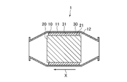
- FIG. 1 is an explanatory diagram illustrating an example of a gas processing apparatus (hereinafter referred to as “the present apparatus 1”) according to the present embodiment.
- the apparatus 1 includes a processing structure 20, a metal casing 30 that houses the processing structure 20, and an inorganic material disposed between the processing structure 20 and the casing 30. And a fiber holding material 10 (a gas processing device holding material according to this embodiment).
- a part of the casing 30 is omitted, and the processing structure 20 and the holding material 10 housed in the casing 30 are exposed.
- FIG. 2 is an explanatory view showing an example of a cross section of the device 1 cut in the longitudinal direction (the direction indicated by the arrow X shown in FIGS. 1 and 2). 1 and 2, the arrow X indicates the direction in which the gas to be processed flows through the apparatus 1.
- FIG. 3 is an explanatory diagram showing an example of a cross section of the device 1 cut in a direction orthogonal to the longitudinal direction.
- the present apparatus 1 is used for processing gas such as gas purification. That is, the present apparatus 1 is used, for example, to remove harmful substances and / or particles contained in a gas.
- the apparatus 1 is an exhaust gas processing apparatus that purifies exhaust gas, for example.
- the present apparatus 1 is provided in a vehicle such as an automobile in order to remove harmful substances and / or particles contained in exhaust gas discharged from an internal combustion engine (gasoline engine, diesel engine, etc.).
- the present apparatus 1 is a catalytic converter used for removing harmful substances contained in exhaust gas in a vehicle such as an automobile. Moreover, this apparatus 1 is DPF used in order to remove the particle
- the processing structure 20 is a structure having a function of processing a gas. That is, when the present apparatus 1 is a catalytic converter, the processing structure 20 is a catalyst carrier having a catalyst for purifying gas and a carrier for carrying the catalyst.
- the catalyst is a catalyst for removing harmful substances (carbon monoxide, hydrocarbons, nitrogen oxides, etc.) contained in a gas such as exhaust gas. More specifically, the catalyst is a metal catalyst such as a noble metal catalyst (for example, a platinum catalyst).
- the carrier for supporting the catalyst is, for example, a cylindrical molded body (for example, a cylindrical honeycomb-shaped molded body) made of an inorganic material (for example, ceramics such as cordierite).
- the processing structure 20 is a porous body (for example, a filter) that captures the particles in the gas. It is a structure which has. In this case, the processing structure 20 may further include a catalyst or may not include a catalyst.
- the casing 30 is a metal cylindrical body in which a space capable of accommodating the processing structure 20 is formed.
- the metal which comprises the casing 30 is not specifically limited, For example, it is good also as selecting from the group which consists of stainless steel, iron, and aluminum.
- the casing 30 may be, for example, a cylindrical body that can be divided into two along the longitudinal direction of the device 1, or may be an integral cylindrical body that is not divided. In the example shown in the present embodiment, the casing 30 is an integral cylindrical body.
- the holding material 10 is used for holding the processing structure 20 in the casing 30. That is, the holding material 10 is stably pressed into the casing 30 by being press-fitted into the gap between the processing structure 20 and the casing 30.
- the holding material 10 is still purified, for example, with the function of safely holding the processing structure 20 so as to avoid the processing structure 20 from colliding with the casing 30 and being damaged by vibration or the like in the apparatus 1. It is required to have a function of sealing the gap so that no gas leaks downstream from the gap between the processing structure 20 and the casing 30. Further, when a high-temperature gas (for example, 200 to 900 ° C.) such as exhaust gas circulates in the apparatus 1, the holding material 10 is required to have heat resistance and heat insulation.
- a high-temperature gas for example, 200 to 900 ° C.
- the holding material 10 is a molded body made of inorganic fibers. That is, the holding material 10 contains an inorganic fiber as a main component. Specifically, the holding material 10 contains 90 mass% or more of inorganic fibers, for example.
- the inorganic fiber is not particularly limited as long as it is an inorganic fiber that does not deteriorate or hardly deteriorates when the apparatus 1 is used (gas treatment).
- alumina fiber, mullite fiber, aluminosilicate fiber, silica fiber, soluble inorganic fiber It is preferable that it is 1 or more types selected from the group which consists of a fiber, glass fiber, and rock wool.
- the alumina fiber is an amorphous fiber or a polycrystalline fiber containing alumina (Al 2 O 3 ) as a main component.
- the alumina fiber may contain, for example, 70% by mass or more of alumina.
- the content of alumina in the alumina fiber may be, for example, 80% by mass or more, 90% by mass or more, and 95% by mass or more.
- the mullite fiber is an amorphous fiber or a polycrystalline fiber mainly composed of alumina (Al 2 O 3 ) and silica (SiO 2 ).
- the mullite fiber may contain, for example, 90% by mass or more of alumina (Al 2 O 3 ) and silica (SiO 2 ) in total.
- the mullite fiber may have, for example, an alumina / silica mass ratio of 70/30 to 85/15.
- the aluminosilicate fiber is an amorphous fiber or a polycrystalline fiber mainly composed of alumina and silica.
- the aluminosilicate fiber may have, for example, an alumina / silica mass ratio of 60/40 to 40/60.
- the silica fiber is an amorphous fiber or a polycrystalline fiber mainly composed of silica.
- the silica fiber may contain, for example, 90% by mass or more of silica.
- the content of silica in the silica fiber may be, for example, 93% by mass or more, or 95% by mass or more.
- Soluble inorganic fibers are artificial amorphous inorganic fibers that have been given solubility in vivo.
- This soluble inorganic fiber is not particularly limited as long as it is an inorganic fiber having solubility (degradability) that is decomposed in vivo, for example, the dissolution rate in physiological saline at 40 ° C. is 1% or more, An inorganic fiber having a heat shrinkage of 5% or less when heated at 1000 ° C. for 8 hours is preferable.
- the dissolution rate of the physiological saline of the soluble inorganic fiber can be measured, for example, as follows. That is, first, 1 g of a sample prepared by pulverizing soluble inorganic fibers to 200 mesh or less and 150 mL of physiological saline are placed in an Erlenmeyer flask (volume: 300 mL) and placed in an incubator at 40 ° C. Next, the Erlenmeyer flask is subjected to horizontal vibration at 120 revolutions per minute for 50 hours and filtered. And the element contained in a filtrate is quantified with an ICP emission spectrometer. Based on the quantified element content and the composition and weight of the original sample, a solubility representing the ratio of the amount of element eluted from the sample into the filtrate (weight reduction rate of the sample due to dissolution) is obtained.
- the glass fiber is an inorganic fiber that is made into a fiber by melting and pulling alkali-free glass such as quartz glass.
- the glass fiber is also referred to as glass fiber or glass wool.
- the glass fiber either short fiber or continuous fiber (long fiber) may be used.
- the glass fiber for example, SiO 2 is 52 to 56 mass%, Al 2 O 3 is 12 to 16 mass%, MgO is 0 to 5 mass%, CaO is 16 to 25 mass%, B 2 O 3 to 5-10 mass%, Na 2 O and / or K 2 O 0 to 1 mass%, E glass fiber containing TiO 2 0 to 1 mass%, SiO 2 62 to 65 mass%, Al 2 20 to 25 mass% of O 3 , 10 to 15 mass% of MgO, 0 to 1 mass% of CaO, 0 to 1 mass% of B 2 O 3 , 0 to 1 mass of Na 2 O and / or K 2 O %, TiO 2 containing 0 to 1% by mass T glass fiber, SiO 2 56 to 62% by mass, Al 2 O 3 9 to 15% by mass, MgO 0 to 5% by mass, CaO 17 to 25% by mass %, the B 2 O 3 0-1 wt%, Na 2 O and / or K 2 O 0 to 1 mass%,
- Rock wool is an artificial mineral inorganic fiber mainly composed of silicon dioxide (SiO 2 ) and calcium oxide (CaO). Rock wool is produced by mixing lime or the like with basalt, iron slag, etc., and melting at high temperature. Rock wool varies depending on the raw material, but generally, SiO 2 is 35 to 45 mass%, Al 2 O 3 is 10 to 20 mass%, MgO is 4 to 8 mass%, and CaO is 20 to 40 mass%. Fe 2 O 3 is contained in an amount of 0 to 10% by mass and MnO is contained in an amount of 0 to 4% by mass.
- Inorganic fibers for example, silica fibers and aluminosilicate fibers
- the heat resistance of the inorganic fiber is improved.
- the silica fiber may be obtained by removing the alkali component by subjecting the glass fiber to an acid treatment to increase the silica component.
- the fine voids generated by the acid treatment in the production process of the silica fiber are filled by thermal contraction of the silica fiber, Its heat resistance is improved.
- the average fiber diameter of the inorganic fibers is preferably 2 to 13 ⁇ m, for example.
- the holding material 10 may contain a binder (organic binder and / or inorganic binder) in addition to the inorganic fiber, or may contain a binder and / or filler (for example, 10 to 70% by mass vermiculite). Good.
- the bulk density of the holding material 10 is a desired range in a state where the holding material 10 is incorporated in the apparatus 1 (that is, the holding material 10 is press-fitted between the processing structure 20 and the casing 30). For example, it is set as appropriate according to the size of the gap (gap) between the processing structure 20 and the casing 30. Specifically, the bulk density of the holding material 10 before being inserted into the casing 30 may be, for example, 0.15 to 0.75 g / cm 3 .
- the shape of the holding material 10 is not particularly limited as long as the processing structure 20 can be held in the casing 30. That is, the holding material 10 may be, for example, a plate-like body (film, sheet, blanket, mat, etc.) or a cylindrical body.
- one end and the other end of the plate-shaped holding material 10 may be formed in a corresponding shape that can be fitted. That is, in the example shown in FIG. 1, one end and the other end of the holding material 10 are respectively formed in a corresponding convex shape and concave shape, and one end of the holding material 10 disposed on the outer periphery of the processing structure 20. The other end is fitted.
- the method for producing a molded body made of inorganic fibers constituting the holding material 10 is not particularly limited, and either a wet method or a dry method may be used. That is, this molded body is manufactured by, for example, dehydration molding.
- an inorganic fiber for forming the holding material 10 and an organic binder for example, rubber, water-soluble organic polymer compound, thermoplastic resin, thermosetting, in a dehydrating mold having a predetermined shape.
- An aqueous slurry containing a resin or the like An aqueous slurry containing a resin or the like.
- an inorganic fiber molded body (wet molded body) having a shape corresponding to the shape of the mold is obtained.
- this wet molded body is compressed so that properties such as its bulk density and / or basis weight are within a desired range, and dried to finally obtain a molded body made of inorganic fibers.
- the inorganic fiber molded body constituting the holding material 10 may be manufactured, for example, by a dry method in which the collected inorganic fibers are needle processed. That is, in this case, the inorganic fiber molded body is produced as, for example, a so-called blanket, needle mat, or sewing mat.
- a molded body made of an inorganic fiber manufactured by a wet method or a dry method may be used as the holding material 10 as it is.
- a fiber sheet for example, a woven or non-woven fabric of organic fibers and / or inorganic fibers
- the holding material having the inorganic fiber molded body and the fiber sheet. 10 may be manufactured.
- the present apparatus 1 is assembled by disposing the processing structure 20 and the holding material 10 in the casing 30. That is, for example, first, the holding material 10 is disposed on the outer periphery of the processing structure 20 to produce an assembly including the processing structure 20 and the holding material 10. Specifically, when the holding material 10 is plate-shaped, the holding material 10 is wound around the outer periphery of the processing structure 20 to produce an assembly. Further, when the holding material 10 is cylindrical, the assembly is manufactured by inserting the processing structure 20 into the inner space of the holding material 10.
- this assembly is placed in the casing 30. That is, when the casing 30 is an integral type that cannot be divided, the assembly is press-fitted into the casing 30 from an opening at one end in the longitudinal direction of the casing 30 (so-called stuffing method).
- stuffing method since the processing structure 20 is a molded body having high rigidity, the holding material 10 is press-fitted between the processing structure 20 and the casing 30.
- the casing 30 when the casing 30 can be divided, the assembly is sandwiched between a part of the divided casing 30 and the other part, and then the casing 30 is integrated (a so-called clamshell method). Also in this case, the holding material 10 is press-fitted between the processing structure 20 and the casing 30.
- the casing 30 is integrated by using and / or welding a fastening member such as a bolt and a nut, for example.
- the apparatus 1 as described above is used to process the gas. That is, the gas to be processed is processed by circulating the gas in the processing structure 20 of the apparatus 1.
- a gas such as exhaust gas flows from one end of the casing 30 in the direction indicated by the arrow X, and the gas circulates inside the processing structure 20. During this time, the purified and purified gas flows out of the apparatus 1 from the other end of the casing 30.
- a pipe for guiding a gas such as exhaust gas from the upstream side to the apparatus 1 and a purified gas downstream from the apparatus 1 are provided.
- the pipes leading to are respectively connected.
- FIG. 4 is an explanatory view showing, in an enlarged manner, a part of a cross section of the gas processing device surrounded by a one-dot chain line IV shown in FIG.
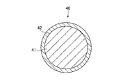
- FIG. 5 is an explanatory diagram showing an example of a cross section of the capsule particle 40 according to the present embodiment.
- one of the characteristic features of the device 1 is that the device 1 encapsulates the liquid particles 41 in the inner surface 31 and / or the holding material 10 of the casing 30. It is to carry.
- the capsule particle 40 is a particle having a liquid 41 and a shell 42 that accommodates the liquid 41 therein.
- the conditions of the capsule particles 41 such as the type of the liquid 41, the type of material constituting the shell 42, and the combination of the liquid 41 and the shell 42, are appropriately determined according to the purpose.
- the liquid 41 is not particularly limited as long as it can be sealed in the shell 42. A specific example of the liquid 41 will be described in detail later.
- the shell 42 is not particularly limited as long as the liquid 41 can be sealed therein and can be broken and / or expanded as described later.
- the material constituting the shell 42 is not particularly limited, and an organic compound and / or an inorganic compound is used.
- an organic compound for example, an organic polymer is preferably used.
- a resin and / or a gelatin polymer is preferably used.
- the resin for example, a thermoplastic resin and / or a thermosetting resin is used.
- the organic polymer may be, for example, one or more selected from the group consisting of melamine resin, urethane resin, urea-formalin resin, gelatin, and gelatin-rubber.
- the method for producing the capsule particles 40 is not particularly limited, and for example, a known method may be used. That is, the capsule particle 40 having the organic polymer shell 42 may be manufactured by, for example, a chemical polymerization method in a liquid phase, or may be manufactured by a so-called coacervation method. .
- the size of the capsule particles 40 is not particularly limited and is appropriately determined according to the purpose.
- the average particle size of the capsule particles 40 may be in the range of 1 to 5000 ⁇ m, and may be 100 to 1000 ⁇ m. It may be within the range.
- the capsule particles 40 when destroying the capsule particles 40 by pressing as described later, for example, the capsule particles 40 may be more easily destroyed by reducing the thickness of the shell 42 of the capsule particles 40. it can.
- the capsule particle 40 can be more easily broken by increasing the size of the capsule particle 40 so that it does not easily pass through the fiber gap constituting the holding material 10 or does not pass.
- the shape of the capsule particle 40 is spherical in the example shown in FIG. 5, but is not limited to this.
- irregularities may be formed on the outer surface and / or inner surface of the shell 42. It may be a simple shape.
- the capsule particles 40 are carried on the inner surface 31 of the casing 30 and / or the holding material 10.
- the capsule particles 40 may be carried on the entire inner surface 31 or may be carried on a part of the surface. Good.
- the capsule particles 40 are carried on the surface and / or the inside of the holding material 10.
- the capsule particles 40 may be carried on the entire surface, or may be carried on a part of the surface.
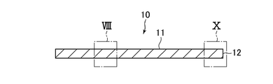
- FIG. 6 is an explanatory view showing an example of the holding material 10 in plan view
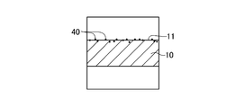
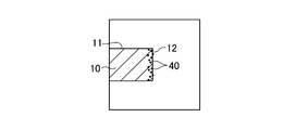
- FIG. 7 is an explanatory view showing an example of a cross section of the holding material cut along the line VII-VII shown in FIG. 8 and FIG. 9 are explanatory views showing in enlargement an example of a part of the cross section of the holding material surrounded by the alternate long and short dash line VIII shown in FIG. 7 and another example
- maintenance material enclosed with the dashed-dotted line X shown in FIG. 11 is an explanatory view showing another example of the cross section of the holding material cut along the line VII-VII shown in FIG. 6, and FIG. 12 shows the holding material surrounded by the alternate long and short dash line XII shown in FIG. It is explanatory drawing which expands and shows an example of a part of cross section.
- the capsule particles 40 may be carried on the surface (outer surface 11) of the holding material 10 on the casing 30 side, and / or as shown in FIG.
- the material 10 is carried on the upstream end face (upstream end face 12) (see also FIG. 2) in the direction in which the gas flows through the apparatus 1 (the direction indicated by the arrow X shown in FIGS. 1 and 2). Also good.
- the capsule particles 40 may be carried on the whole or a part of the other surface of the holding material 10. Further, for example, as shown in FIG. 9, the holding material 10 may carry capsule particles 40 therein.
- the holding member 10 includes a base member 10a made of an inorganic fiber molded body and a surface member 10b made of a fiber sheet laminated on the casing 30 side of the base member 10a. It is good as well. That is, in the example shown in FIG.11 and FIG.12, the holding material 10 has the base member 10a and the surface member 10b laminated
- This fiber sheet is a sheet of organic fibers and / or inorganic fibers.
- the fiber sheet may be a woven fabric or a non-woven fabric. That is, the fiber sheet may be, for example, a woven fabric or a nonwoven fabric made of organic fibers.
- the organic fiber may be, for example, one or more fibers selected from the group consisting of polyethylene terephthalate (PET), polyethylene (PE), and polypropylene (PP).
- the holding material 10 when the holding material 10 includes the base member 10 a and the surface member 10 b (for example, an organic fiber sheet), the holding material 10 is pressed between the processing structure 20 and the casing 30.
- the frictional resistance between the holding material 10 and the casing 30 is compared with the case where the holding material 10 does not have the surface member 10b (for example, when the holding material 10 includes only the base member 10a). It may be reduced.
- the capsule particles 40 are carried on the base member 10a and / or the surface member 10b. That is, in the example shown in FIG. 12, the capsule particles 40 are carried on the surface member 10b. In this case, the capsule particles 40 are carried on the surface of the surface member 10b (for example, the outer surface 11b which is the surface on the casing 30 side) and / or inside. The capsule particles 40 may be carried on the surface (for example, the outer surface 11a) and / or the inside of the base member 10a.
- the method of supporting the capsule particles 40 on the inner surface 31 of the casing 30 and / or the holding material 10 is not particularly limited, and an appropriate method is adopted depending on the purpose. That is, when the capsule particles 40 are carried on the inner surface 31 of the casing 30, for example, a dispersion liquid containing the capsule particles 40 may be applied to the inner surface 31 and dried. May be applied to the inner surface 31.
- the holding material 10 carrying the capsule particles 40 is manufactured by a method including carrying the capsule particles 40 on the holding material 10 as follows. That is, when the capsule particles 40 are carried on the surface of the holding material 10 (for example, the outer surface 11 and / or the upstream end surface 12), for example, a dispersion liquid containing the capsule particles 40 is applied to the surface of the holding material 10. It is good also as drying.
- the holding member 10 includes the base member 10a and the surface member 10b as described above, for example, the outer surface 11a and / or the base member 10a on which the surface member 10b is not laminated with the dispersion liquid including the capsule particles 40 is used. Or it is good also as applying to the outer surface 11b of the said surface member 10b laminated
- the capsule particles 40 when carried inside the holding material 10, for example, the capsule particles 40 may be added to a slurry that is subjected to dehydration in a wet method, or in the process of collecting cotton in a dry method. Capsule particles 40 may be added.
- the manufacturing method of the present apparatus 1 includes the preparation of the casing 30 carrying the capsule particles 40 on the inner surface 31 and / or the holding material 10 carrying the capsule particles 40 and the processing. Disposing the holding material 10 between the structure 20 and the casing 30.
- the capsule particles 40 are supported in advance on the inner surface 31 of the casing 30 and / or the holding material 10, and then the processing structure 20 and the holding material 10 are arranged in the casing 30.
- the present method can be achieved by pressing the capsule particles 40 between the holding material 10 and the casing 30 when the holding material 10 is disposed between the processing structure 20 and the casing 30, or the processing structure. It may further include destroying the capsule particles 40 by heating the capsule particles 40 after the holding material 10 is disposed between the body 20 and the casing 30.
- the capsule particles 40 are supported in advance on the inner surface 31 of the casing 30 and / or the holding material 10, and then, in the inner surface 31 of the casing 30 and / or the holding material 10.
- the liquid 41 contained in the capsule particles 40 is brought into contact with the inner surface 31 of the casing 30 and / or the holding material 10.
- a casing 30 carrying the capsule particles 40 on the inner surface 31 and / or a holding material 10 carrying the capsule particles 40 on the outer surface 11 are prepared, and the space between the processing structure 20 and the casing 30 is prepared.
- the holding material 10 is press-fitted into the casing 41, the capsule particles 40 are destroyed by pressing the capsule particles 40 between the casing 30 and the holding material 10, and the liquid 41 leaks from the capsule particles 40.
- the holding material 10 is placed between the processing structure 20 and the casing 30 with the liquid 41 applied to the inner surface 31 and the outer surface 11. It is good also as pushing forward in between.
- the liquid 41 contained in the capsule particles 40 is used as a lubricant when the holding material 10 is press-fitted between the processing structure 20 and the casing 30. That is, as a result of the liquid 41 leaking from the broken capsule particles 40 being applied to the inner surface 31 of the casing 30 and the outer surface 11 of the holding material 10, the inner surface 31 of the casing 30 and the outer surface of the holding material 10 The frictional resistance between the two is reduced. Therefore, it is possible to smoothly press the holding material 10 between the processing structure 20 and the casing 30.
- the holding material 10 when the holding material 10 is press-fitted between the processing structure 20 and the casing 30, the inorganic fibers constituting the holding material 10 are effectively prevented from being destroyed, so that The holding force by the holding material 10 can be effectively increased.
- the apparatus 1 while reducing the bulk density of the holding material 10 (that is, while reducing the amount of inorganic fibers used for manufacturing the holding material 10), the apparatus 1 exhibits a holding force equal to or higher than that of the conventional device. be able to. Further, for example, the device 1 can exhibit a higher holding force than before without reducing the bulk density of the holding material 10.
- the liquid 41 when the liquid 41 is directly applied to the inner surface 31 of the casing 30 and / or the outer surface 11 of the holding material 10 without using the capsule particles 40, in order to prevent the liquid 41 from drying, There is a limitation that the liquid 41 must be applied immediately before the holding material 10 is press-fitted between the processing structure 20 and the casing 30. For this reason, an operator who press-fits the holding material 10 into the casing 30 needs to apply the liquid 41.
- the liquid 41 can be used without causing the above-described disadvantages.
- the liquid 41 used as a lubricant is applied to the inner surface 31 of the casing 30 and the outer surface 11 of the holding material 10, so that the inner surface 31 of the casing 30 and the outer surface 11 of the holding material 10 If it is the liquid which reduces the frictional resistance between, it will not be restricted especially.
- the liquid 41 for example, one or more selected from the group consisting of water, an aqueous solution containing a surfactant, silicone oil, and lubricating oil may be used, and water or a surfactant may be used. It is preferred to use an aqueous solution containing.
- the capsule particle 40 when the liquid 41 in the capsule particle 40 includes a compound having a structural unit represented by the following general formula (I) (hereinafter referred to as “compound I”), the capsule particle 40
- the casing 31 carried on the surface 31 and / or the holding material 10 carrying the capsule particles 40 carried on the outer surface 11 are prepared, and when the holding material 10 is disposed between the processing structure 20 and the casing 30
- the capsule particles 40 are heated by pressing the capsule particles 40 between the casing 30 and the holding material 10 or after the holding material 10 is disposed between the processing structure 20 and the casing 30.
- the compound I that is in contact with the inner surface 31 and the outer surface 11 between the inner surface 31 and the outer surface 11 is It is also possible to form the non-adhesive layer.
- R 1 is independently a hydrogen atom, an alkyl group having 1 to 5 carbon atoms, an alkoxy group having 1 to 5 carbon atoms, a phenyl group or a hydroxyl group, and n is 1 or more. It is an integer.
- R ⁇ 1 > may be the same and may differ. That is, the plurality of R 1 bonded to one silicon atom (Si) may be the same or different. Moreover, several R ⁇ 1 > couple
- n is a range in which an adhesive layer containing Compound I can be formed (for example, a range in which the compound I or the liquid 41 containing the Compound I can be applied).
- n may be an integer from 1 to 2000, for example.
- the liquid 41 contained in the capsule particles 40 is used as an adhesive that increases the frictional resistance between the casing 30 and the holding material 10. That is, as a result of applying the liquid 41 containing the compound I leaked from the capsule particles 40 to the inner surface 31 of the casing 30 and the outer surface 11 of the holding material 10, the inner surface 31 and the outer surface 11 Is in contact via an adhesive layer containing the compound I.
- the inner surface 31 and the outer surface 11 are effectively obtained by heating the adhesive layer and curing the adhesive layer in a state where the outer surface 11 is in contact with the adhesive layer containing the compound I. Glued to. Therefore, in this device 1, the frictional resistance between the inner surface 31 of the casing 30 and the outer surface 11 of the holding material 10 can be remarkably increased.
- the temperature at which the capsule particles 40 are heated to destroy the capsule particles 40 is not particularly limited as long as the capsule particles 40 are destroyed. That is, for example, when the shell 42 of the capsule particle 40 is made of resin, the capsule particle 40 may be heated at a temperature equal to or higher than the melting point or decomposition temperature of the resin.
- the method for heating the capsule particles 40 is not particularly limited as long as the capsule particles 40 are destroyed. That is, for example, a method of heating the apparatus 1 in an atmosphere (for example, an electric furnace) in which the temperature is maintained at a predetermined heating temperature, a method of using heat at the time of welding the casing 30 (for example, capsule particles 40 by welding). The temperature of the inner surface 31 of the casing 30 in contact with the heater becomes a predetermined heating temperature), a method of heating the casing 30 with a heating device such as a heater, or so that the capsule particles 40 are heated at a predetermined heating temperature.
- an atmosphere for example, an electric furnace
- a method of using heat at the time of welding the casing 30 for example, capsule particles 40 by welding.
- the temperature of the inner surface 31 of the casing 30 in contact with the heater becomes a predetermined heating temperature
- a method of heating the casing 30 with a heating device such as a heater, or so that the capsule particles 40 are heated at a predetermined heating temperature.
- a method of circulating a gas having a relatively high temperature (a temperature equal to or higher than the heating temperature) in the processing structure 20 of the apparatus 1 for example, a gas (exhaust gas) to be processed is circulated through the apparatus 1. Or a gas different from the gas may be circulated).
- the temperature at which the compound I is heated to bond the inner surface 31 of the casing 30 and the outer surface 11 of the holding material 10 is not particularly limited as long as the adhesive layer containing the compound I is cured, for example, It may be 150 ° C or higher, may be 250 ° C or higher, may be 350 ° C or higher, may be 450 ° C or higher, and may be 500 ° C or higher.
- the upper limit of the temperature at which Compound I is heated is not particularly limited as long as the performance of the apparatus 1 is not significantly impaired, but the heating temperature may be, for example, 1000 ° C. or less, and 900 ° C. or less. It is good also as being.
- the upper limit value and lower limit value of the heating temperature described above can be arbitrarily combined.
- Compound I may be, for example, a compound represented by the following general formula (II) (hereinafter referred to as “Compound II”).
- R 2 is independently a hydrogen atom or an alkyl group having 1 to 5 carbon atoms, and n is an integer of 1 or more.
- This compound II can be said to be, for example, a compound represented by the following general formula: Si n O n-1 (OR 2 ) 2n + 2 (R 2 is a hydrogen atom or an alkyl group having 1 to 5 carbon atoms) , N is an integer greater than or equal to 1.)
- R 2 may independently be a hydrogen atom or an alkyl group having 1 to 3 carbon atoms.
- n may be an integer of 2 or more.
- Compound II is a polycondensate, and is preferable in that it is less volatile than, for example, a monomer.
- n is within a range in which an adhesive layer containing the compound II can be formed (for example, a range in which the compound II or the liquid 41 containing the compound II can be applied).
- n may be an integer from 1 to 1000, for example, or may be an integer from 1 to 100.
- n in the general formula (II) may be an integer of 2 to 1000, for example, or an integer of 2 to 100.
- R ⁇ 2 > may be the same and may differ. That is, the plurality of R 2 bonded to one silicon atom (Si) via an oxygen atom (O) may be the same or different. Moreover, several R ⁇ 2 > couple
- the compound II when at least one R 2 is a hydrogen atom, the compound II is silanol or a polymer thereof (polysilanol). That is, in the general formula (II), when a part of R 2 is a hydrogen atom and the other R 2 is an alkyl group, the compound II is an alkoxysilanol or a polycondensate thereof.
- compound II for example, one or more selected from the group consisting of monoalkoxysilanol or polycondensate thereof, dialkoxysilanol or polycondensate thereof and trialkoxysilanol or polycondensate thereof is used. be able to.
- the alkoxysilanol has a plurality of alkoxy groups, the plurality of alkoxy groups may all be the same, or some of the alkoxy groups may be different from other alkoxy groups.
- the alkoxysilanol or polycondensate thereof may be produced by hydrolysis of an alkoxysilane or polycondensate thereof described later.
- the compound II when all R 2 are alkyl groups, the compound II is an alkoxysilane (alkyl silicate) or a polycondensate thereof (alkyl polysilicate). That is, in this case, compound II is tetraalkoxysilane or a polycondensate thereof.
- compound II for example, tetramethoxysilane (methyl silicate) or a polycondensate thereof (methyl polysilicate) and tetraethoxysilane (ethyl silicate) or a polycondensate thereof (ethyl polysilicate) are used. One or more selected can be used.
- the liquid 41 When the liquid 41 is a solution containing the compound II, the liquid 41 preferably contains alcohol as a solvent.
- the alcohol for example, an alcohol having 1 to 3 carbon atoms such as methanol, ethanol, isopropanol or the like is preferably used.
- the liquid 41 may include water as a solvent.
- the alkoxy An adhesive layer containing an alkoxysilanol produced by hydrolysis of silane or its polycondensate or its polycondensate can be formed.
- hydrolysis of alkoxysilane or its polycondensate is also possible in the presence of water in the gas phase (for example, air).
- a hydrolysis reaction of alkoxysilane or a polycondensate thereof occurs, a polycondensation reaction of the alkoxysilane or a polycondensate thereof usually also occurs in parallel.
- the concentration of the compound II contained in the liquid 41 is appropriately determined within a range suitable for application of the liquid 41. For example, it is preferably 0.1 to 50% by mass in terms of SiO 2 solid content, and SiO 2 More preferably, it is 0.5 to 20% by mass in terms of solid content.
- the adhesive layer formed by applying the liquid 41 containing the compound II to the inner surface 31 of the casing 30 and / or the outer surface 11 of the holding material 10 may be a gel.
- the compound I may be a compound represented by the following general formula (III) (hereinafter referred to as “compound III”).
- R 3 is independently a hydrogen atom, an alkyl group having 1 to 5 carbon atoms, an alkoxy group having 1 to 5 carbon atoms, a phenyl group or a hydroxyl group
- X is independently a hydrogen atom.
- R ⁇ 3 > may be the same and may differ. That is, the plurality of R 3 bonded to one silicon atom (Si) may be the same or different. Moreover, several R ⁇ 3 > couple
- R 3 may independently be a hydrogen atom or an alkyl group having 1 to 5 carbon atoms.
- the plurality of R 3 may be the same or different.
- X may independently be a hydrogen atom, an alkyl group having 1 to 5 carbon atoms, an aryl group having 6 to 12 carbon atoms, a hydroxyl group, or another organic group. Several X may be the same and may differ.
- the other organic group is not particularly limited as long as it does not interfere with the effect of the compound III.
- the plurality of R 3 may be the same or different.
- the plurality of other organic groups may be the same or different.
- n and m are within a range in which an adhesive layer containing the compound III can be formed (for example, a range having fluidity to which the compound III or the liquid 41 containing the compound III can be applied).
- n and m may be integers such that the sum of n and m is in the range of 2 to 2000, for example.
- the compound III has fluidity suitable for realizing strong adhesion by the anchor effect between the inner surface 31 of the casing 30 and the outer surface 11 of the holding material 10 (comparison) A low viscosity).
- R 3 , X, n and m described above can be arbitrarily combined.
- Compound I may be a compound represented by the following general formula (IV) (hereinafter referred to as “compound IV”).
- R 4 is independently a hydrogen atom, an alkyl group having 1 to 5 carbon atoms, an alkoxy group having 1 to 5 carbon atoms, a phenyl group or a hydroxyl group, and n is an integer of 1 or more It is.
- R 4 may independently be a hydrogen atom or an alkyl group having 1 to 5 carbon atoms.
- the plurality of R 4 may be the same or different. That is, the plurality of R 4 bonded to one silicon atom (Si) may be the same or different. Moreover, several R ⁇ 4 > couple
- Compound IV is a dialkyl polysiloxane.
- the upper limit value of n is within a range in which an adhesive layer containing the compound IV can be formed (for example, a range in which the compound IV or the liquid 41 containing the compound IV can be applied).
- n may be an integer of 1 to 2000, for example.
- the compound IV has fluidity (relatively low viscosity) suitable for realizing strong adhesion due to the anchor effect between the inner surface 31 of the casing 30 and the outer surface 11 of the holding material 10. It can be made liquid.
- the compound I may be a silicone oil. That is, in this case, the compound I is a silicone oil having a structural unit represented by the above general formula (I).
- the upper limit value of n is a range in which an adhesive layer containing silicone oil can be formed (for example, a range in which the silicone oil or the liquid 41 containing the silicone oil can be applied). ) Is not particularly limited, but n may be an integer of 1 to 2000, for example.
- a silicone oil is good also as being the above-mentioned compound III or compound IV, for example.
- Silicone oil has fluidity (relatively low viscosity) suitable for realizing strong adhesion due to the anchor effect between the inner surface 31 of the casing 30 and the outer surface 11 of the holding material 10. Silicone oil may be used after being diluted by mixing with an appropriate solvent (for example, an organic solvent such as toluene).
- an appropriate solvent for example, an organic solvent such as toluene.
- the inorganic fiber constituting the outer surface 11 of the holding material 10 includes a soluble fiber
- the liquid 41 in the capsule particle 40 dissolves the soluble fiber
- the capsule particle A casing 31 carrying 40 on the inner surface 31 and / or a holding material 10 carrying the capsule particles 40 on the outer surface 11 are prepared, and the holding material 10 is arranged between the processing structure 20 and the casing 30.
- the capsule particles 40 are pressed by pressing the capsule particles 40 between the casing 30 and the holding material 10 or after the holding material 10 is disposed between the processing structure 20 and the casing 30.
- the capsule particles 40 are broken by heating the leaked fibers from the capsule particles 40 into the soluble fibers constituting the outer surface 11. Contacting the body 41, by dissolving a portion of the soluble fiber, and the outer surface 11 and the inner surface 31, it may be bonded via a lysate of the soluble fiber.
- the soluble fiber constituting the outer surface 11 of the holding material 10 and the liquid 41 contained in the capsule particles 40 are used as an adhesive that increases the frictional resistance between the casing 30 and the holding material 10.
- the liquid 41 is not particularly limited as long as it dissolves soluble fibers, but is preferably water, for example.
- the water is not particularly limited, and purified water or tap water may be used, or physiological saline may be used. In particular, physiological saline is preferably used.
- the capsule particle 40 when the liquid 41 in the capsule particle 40 includes a compound that increases the surface roughness of the inner surface 31 by contacting the inner surface 31 of the casing 30, the capsule particle 40 is moved to the inner surface 31.
- the holding material 10 carrying the casing 31 and / or the capsule particles 40 carried on the outer surface 11 is prepared, and the holding material 10 is disposed when the holding material 10 is disposed between the processing structure 20 and the casing 30. 10 by pressing the capsule particles 40 between the casing 30 and the casing 30 or by heating the capsule particles 40 after the holding material 10 is disposed between the processing structure 20 and the casing 30.
- the capsule particles 40 are destroyed, the liquid leaked from the capsule particles 40 is brought into contact with the inner surface 31, and the inner surface 3 Increase the surface roughness of the.
- the liquid 41 contains a compound that corrodes the metal constituting the inner surface 31 of the casing 30, the inner surface 31 is corroded by applying the liquid 41 to the inner surface 31, The surface roughness of the inner surface 31 increases. As a result, in the present apparatus 1, the frictional resistance between the inner surface 31 of the casing 30 and the outer surface 11 of the holding material 10 is remarkably increased.
- the liquid 41 is not particularly limited as long as it contains a compound that corrodes the metallic inner surface 31 of the casing 30.
- the liquid 41 is composed of an acid (specifically, for example, acetic acid, dilute sulfuric acid, and dilute hydrochloric acid).
- an acid specifically, for example, acetic acid, dilute sulfuric acid, and dilute hydrochloric acid.
- One or more selected from the group) and one or more selected from the group consisting of a chlorine-containing aqueous solution for example, an aqueous solution in which a chloride such as sodium chloride is dissolved
- a chlorine-containing aqueous solution for example, an aqueous solution in which a chloride such as sodium chloride is dissolved
- the liquid 41 includes a compound that forms a solid that increases the surface roughness of the inner surface 31 on the inner surface 31 of the casing 30, the liquid 41 is applied to the inner surface 31, By forming the solid matter on the surface 31, the surface roughness of the inner surface 31 increases. As a result, in the present apparatus 1, the frictional resistance between the inner surface 31 of the casing 30 and the outer surface 11 of the holding material 10 is remarkably increased.
- the liquid 41 is not particularly limited as long as it includes a compound that forms a solid substance that increases the surface roughness of the inner surface 31 on the inner surface 31 of the casing 30.
- it may include one or more selected from the group consisting of alumina sol, silica sol, titania sol, and zirconia sol.
- alumina sol silica sol
- titania sol titania sol
- zirconia sol zirconia sol
- the holding material 10 includes a base member 10 a made of inorganic fibers and a surface member 10 b made of a fiber sheet made of organic fibers, and the liquid 41 in the capsule particles 40.
- the organic fiber constituting the surface member 10b is dissolved, the casing 31 carrying the capsule particles 40 on the inner surface 31 and / or the capsule particles 40 are replaced with the surface member 10b and / or When preparing the holding material 10 (see FIG.
- the base member 10a for example, the outer surface 11a of the base member 10a
- the holding material 10 between the processing structure 20 and the casing 30
- the capsule particles 40 are heated after disposing the holding material 10 on the surface, thereby destroying the capsule particles 40 and supplying the liquid 41 leaked from the capsule particles 40 to the organic fibers constituting the surface member 10b. It is good also as making it contact, melt
- the opening is formed by bringing the inorganic fiber constituting the base member 10a of the holding material 10 and the inner surface 31 of the casing 30 into contact with each other through the opening formed in the surface member 10b of the holding material 10.
- the frictional resistance between the holding material 10 and the casing 30 is increased as compared with the case where it is not performed.
- the holding member 10 can be smoothly press-fitted between the processing structure 20 and the casing 30, and an opening is formed in the surface member 10b after the press-fitting.
- the frictional resistance between the holding material 10 and the inner surface 31 can be effectively increased.
- the liquid 41 is not particularly limited as long as it dissolves the organic fibers constituting the surface member 10b.
- the liquid 41 is selected from the group consisting of acids (specifically, for example, acetic acid, dilute sulfuric acid, and dilute hydrochloric acid). 1 type or more) may be included.
- the liquid 41 in the capsule particle 40 is to impregnate the surface of the holding material 10 and harden the surface, as shown in FIG. Preparing the holding material 10 carried on the side end face 12, destroying the capsule particles 40 by heating the capsule particles 40 after arranging the holding material 10 between the processing structure 20 and the casing 30, The liquid 41 leaked from the capsule particles may be applied to the upstream end face 12 and cured.
- the wind erosion resistance of the holding material 10 is effectively improved. That is, for example, when gas is processed using the apparatus 1, when the gas is strongly blown against the upstream end surface 12 of the holding material 10, the upstream end surface 12 is eroded, and as a result, The characteristics of the holding material 10 may be deteriorated. On the other hand, as described above, by precuring the upstream end face 12 of the holding material 10, wind erosion of the upstream end face 12 is effectively prevented.
- the liquid 41 is not particularly limited as long as it is applied to the upstream end surface 12 of the holding material 10 and then cured to cure the upstream end surface 12.
- the liquid 41 is not limited to the above-described compounds I, II, and III.
- Compound IV inorganic binder (for example, one or more selected from the group consisting of alumina, silica, zirconia and magnesia) and one or more selected from the group consisting of titanium nitride may be included.
- the method of curing the upstream end face 12 is appropriately determined according to conditions such as the type of the liquid 41 used.
- the liquid 41 includes the compound I, the compound II, the compound III, or the compound IV.
- the upstream end face 12 coated with the liquid 41 is heated and then cooled, whereby the upstream end face 12 is cured.
- the upstream end face 12 is cured by drying the upstream end face 12 to which the liquid 41 is applied. In this case, the liquid 41 may be dried by heating.
- the method may further include, for example, expanding the capsule particles 40 by heating the capsule particles 40 after the holding material 10 is disposed between the processing structure 20 and the casing 30. .
- the capsule particles 40 are heated to thereby form the capsule particles 40. Evaporation of the encapsulated liquid 41 is promoted, the capsule particles 40 are expanded, and the expanded capsule particles 40 are held in the holding material 10 without being destroyed.
- the holding force by the holding material 10 is effectively increased by expanding and holding the capsule particles 40 in the holding material 10. That is, due to the expansion of the capsule particles 10 in the holding material 10, the pressing force in the radial direction of the apparatus 1 by the holding material 10, specifically, the force pushing the casing 30 outward in the radial direction, and the processing structure 20 The pushing force inward in the radial direction is effectively increased.
- the capsule particles 40 may be carried on the surface and / or inside of the holding material 10, but for example, as shown in FIG. 9, the capsule particles 40 are preferably carried at least inside the holding material 10.
- the temperature at which the capsule particles 40 are heated to expand the capsule particles 40 is not particularly limited as long as the liquid 41 is vaporized and the shell 42 expands, and the type of the liquid 41 and / or the shell 42 is configured. It is determined appropriately according to conditions such as the type of material to be used.
- the shell 42 of the capsule particle 40 is made of resin, and the melting point and / or decomposition temperature of the resin is higher than the boiling point of the liquid 41 in the shell 42, and the resin is equal to or higher than the boiling point.
- the capsule particles 40 can be extended at a temperature lower than the decomposition temperature, the capsule particles 40 are heated at a temperature equal to or higher than the boiling point of the liquid 41 and lower than the melting point of the resin and / or the decomposition temperature.
- the resin constituting the shell 42 of the capsule particle 40 is not particularly limited as long as it is extensible, but may be, for example, a resin exhibiting rubber elasticity.
- the resin may be at least one selected from the group consisting of rubber and / or elastomer (for example, thermoplastic elastomer).
- the liquid 41 is not particularly limited as long as its boiling point is a low-boiling substance having a boiling point equal to or lower than the heating temperature of the capsule particles 40.
- a hydrocarbon having a boiling point of 300 ° C. or lower for example, a hydrocarbon having 5 to 15 carbon atoms, More specifically, for example, it may be a linear alkane having 5 to 15 carbon atoms (pentane (C 5 H 12 ) to pentadecane (C 15 H 32 )).
- the holding material 10 includes an organic binder
- the organic binder when the gas treatment is started by the apparatus 1, the organic binder is heated at a temperature equal to or higher than its melting point and / or decomposition temperature to be fluidized. As a result, the frictional resistance between the holding material 10 and the casing 30 may be temporarily reduced.
- the melting point and / or decomposition temperature of the resin constituting the shell 42 of the capsule particle 40 is higher than the melting point and / or decomposition temperature of the organic binder of the holding material 10 and the liquid 41 in the capsule particle 40
- the capsule is at a temperature that is equal to or higher than the melting point and / or decomposition temperature of the organic binder and lower than the melting point and / or decomposition temperature of the resin.
- the holding material carrying the capsule particles 40 therein. 10 is prepared, and the capsule material 40 is heated after disposing the holding material 10 between the processing structure 20 and the casing 30, thereby destroying the capsule particles 40, and organics inside the holding material 10.
- the liquid 41 leaked from the capsule particles 40 may be brought into contact with the binder to decompose at least a part of the organic binder.
- the liquid 41 is not particularly limited as long as it decomposes the organic binder, and may include, for example, an acid (specifically, for example, one or more selected from the group consisting of acetic acid, dilute sulfuric acid, and dilute hydrochloric acid). .
- an acid specifically, for example, one or more selected from the group consisting of acetic acid, dilute sulfuric acid, and dilute hydrochloric acid.
- a plurality of types of capsule particles 40 containing different types of liquids 41 may be used as the capsule particles 40. That is, for example, by using a plurality of types of capsule particles 40 containing different types of liquids 41 that start a predetermined chemical reaction and / or promote the progress of the predetermined chemical reaction by being mixed. Also good.
- a predetermined chemical reaction is started by mixing with the first capsule particle containing the first liquid and / or the first liquid, and / or a predetermined chemical reaction by the first liquid is performed. It is good also as using the 2nd capsule particle
- the types of the capsule particles 40 are not limited to two, and three or more types of capsule particles 40 may be used.
- a plurality of types of capsule particles 40 are carried on the inner surface 31 of the casing 30 and / or the holding material 10, and then the plurality of types of capsule particles 40 are destroyed by the timing and method described above.
- a plurality of types of liquids 41 leaked from the capsule particles 40 are mixed, a predetermined chemical reaction is started, and / or a predetermined chemical reaction is progressed.
- the combination of the plurality of types of liquids 41 used is not particularly limited and is appropriately determined according to the purpose. That is, for example, the first capsule particle 40 enclosing the liquid 41 containing one or more compounds selected from the group consisting of the above-mentioned compound I, compound II, compound III and compound IV, and the curing reaction of the compound (for example, it is good also as using the 2nd capsule particle 40 which encloses the liquid 41 (for example, water) which accelerates
- a compound that increases the surface roughness of the inner surface 31 by contacting the inner surface 31 of the casing 30 described above for example, the inner surface 31 of the casing 30.
- a compound that forms a solid substance that increases the surface roughness of the inner surface 31 on the inner surface 31 for example, when a plurality of types of liquids 41 are mixed, a compound that increases the surface roughness of the inner surface 31 by contacting the inner surface 31 of the casing 30 described above (for example, the inner surface 31 of the casing 30). And / or a compound that forms a solid substance that increases the surface roughness of the inner surface 31 on the inner surface 31).
- a metal acid solution is used as the liquid 41.
- the first capsule particle 40 to be encapsulated and the second capsule particle 40 to enclose the citric acid solution as the liquid 41 may be used.
- a jig 50 carrying the capsule particles 40 may be used. That is, in this method, for example, as shown in FIGS. 13A and 13B, a cylindrical jig 50 in which a capsule particle 40 containing a liquid 41 is supported on a tapered inner surface 51 is provided in one of the longitudinal directions of the casing 30. The inner surface is disposed while being moved toward the one end of the casing 30 along the inner surface 51 of the jig 50 and the holding material 10 disposed on the outer periphery of the processing structure 20. The capsule particles 40 are broken by pressing the capsule particles 40 between the holding member 10 and the holding material 10, and the liquid 41 leaked from the broken capsule particles 40 is applied to the outer surface 11. The holding member 10 may be further moved along the inner surface 51 of the jig 50 and press-fitted into the casing 30 from the one end.
- the jig 50 is a tapered cylindrical body whose inner diameter is reduced along the longitudinal direction thereof.
- the jig 50 is made of, for example, a metal (for example, stainless steel).
- the minimum inner diameter at one end in the longitudinal direction of the jig 50 is substantially the same as the inner diameter of the casing 30 (for example, the minimum inner diameter of the jig is the same as or slightly smaller than the inner diameter of the casing 30). It has become.
- the jig 50 is arranged so that one end in the longitudinal direction of the minimum inner diameter faces the one end in the longitudinal direction of the casing 30.
- the tapered end portions shown in FIGS. 13A and 13B In the case of manufacturing the apparatus 1 including the casing 30 having tapered end portions as shown in FIGS. 1 and 2, for example, first, the tapered end portions shown in FIGS. 13A and 13B. It is good also as inserting the processing structure 20 and the holding material 10 in the casing 30 which does not have this, and attaching the both ends of the said taper shape to the longitudinal direction both ends of the said casing 30 by means, such as welding.
- the capsule particles 40 are supported on the inner surface 51 of the jig 50 (at least one end portion in the longitudinal direction of the minimum inner diameter).
- the liquid 41 contained in the capsule particles 40 is not particularly limited as long as it can be used as a lubricant as described above.
- the method for supporting the capsule particles 40 on the inner surface 51 of the jig 50 is not particularly limited.
- a dispersion liquid containing the capsule particles 40 may be applied to the inner surface 51 and dried. Forty dry powders may be applied to the inner surface 51.
- the outer diameter of the processing structure 20 is smaller than the inner diameter of the casing 30 and the minimum inner diameter of the jig 50.
- the holding material 10 is disposed between the jig 50 and the processing structure 20 and between the casing 30 and the processing structure 20.
- the thickness of the holding member 10 before being inserted into the casing 30 is larger than the gap between the casing 30 and the processing structure 20 and the gap between the jig 50 and the processing structure 20.
- the assembly having the processing structure 20 and the holding member 10 disposed on the outer periphery of the processing structure 20 is directed toward the casing 30 along the inner surface 51 of the jig 50.
- the holding material 10 is first compressed between the portion with the smallest inner diameter of the inner surface 51 and the processing structure 20.
- the capsule particles 40 carried on the inner surface 51 of the jig 51 are pressed and destroyed between the inner surface 51 and the outer surface 11 of the holding material 10.
- the liquid 41 leaked from the broken capsule particles 40 is applied to the outer surface 11 of the holding material 10 (particularly, the portion compressed on the casing 30 side). That is, the liquid 41 acting as a lubricant is applied to the outer surface 11 of the holding material 10.
- the holding material 10 when the holding material 10 is press-fitted between the processing structure 20 and the casing 30, it is possible to effectively prevent the inorganic fibers constituting the holding material 10 from being destroyed.
- the holding force by the holding material 10 in the device 1 can be effectively increased.
- 1 gas treatment device 10 holding material, 10a base member, 10b surface member, 11, 11a, 11b outer surface, 12 upstream end surface, 20 treatment structure, 21 outer surface, 30 casing, 31 inner surface, 40 capsule particles, 41 liquid, 42 shells, 50 jigs, 51 inner surface.
Landscapes
- Chemical & Material Sciences (AREA)
- Engineering & Computer Science (AREA)
- Chemical Kinetics & Catalysis (AREA)
- Combustion & Propulsion (AREA)
- Mechanical Engineering (AREA)
- General Engineering & Computer Science (AREA)
- Health & Medical Sciences (AREA)
- Toxicology (AREA)
- Exhaust Gas After Treatment (AREA)
- Chemical Or Physical Treatment Of Fibers (AREA)
- Nonwoven Fabrics (AREA)
Description
本発明は、気体処理装置用保持材、気体処理装置及びこれらの製造方法に関し、特に、気体処理装置用保持材及び気体処理装置の特性の向上に関する。
自動車等の車両には、ガソリンエンジンの排気ガスに含まれる一酸化炭素、炭化水素、窒素酸化物等の有害物質を除去するための触媒コンバータや、ディールエンジンの排気ガスに含まれる粒子を除去するためのDPF(Diesel particulate filter)といった気体処理装置が備えられる。
例えば、触媒コンバータとしては、筒状の触媒担体と、当該触媒担体を収容する筒状の金属製ケーシングと、当該触媒担体と当該ケーシングとの間に配置されるマット状の無機繊維製保持材と、を備えたものがある。このような触媒コンバータの保持材としては、従来、例えば、特許文献1において、少なくとも片面に液体潤滑剤が塗布されたアルミナ繊維製の耐熱性マットが記載されている。
しかしながら、保持材の表面に液体を塗布する場合には、様々な不都合が生じ得る。すなわち、例えば、複数の保持材を製造する場合には、当該複数の保持材を積層して保管することがある。しかしながら、一方の表面にのみ液体を塗布した複数の保持材を製造する場合、当該複数の保持材を積層すると、各保持材の他方の表面が当該液体の転写により濡れてしまうといった不都合が生じる。
また、例えば、保持材の表面に液体を塗布し、当該液体を乾燥させることなく、当該保持材をケーシング内に挿入することにより触媒コンバータを組み立てる場合には、当該液体の塗布を当該挿入の直前に行う必要がある。
また、保持材及び触媒コンバータには、その特性や製造時の条件等について様々な要求があるが、従来、当該様々な要求に柔軟に対応できる保持材及び触媒コンバータを実現することは困難であった。
本発明は、上記課題に鑑みて為されたものであって、様々な要求に対応可能な気体処理装置用保持材、気体処理装置及びこれらの製造方法を提供することをその目的の一つとする。
上記課題を解決するための本発明の一実施形態に係る気体処理装置用保持材は、処理構造体と、前記処理構造体を収容する金属製のケーシングとを備えた気体処理装置において、前記処理構造体と前記ケーシングとの間に配置される無機繊維製の保持材であって、液体を内包するカプセル粒子を担持していることを特徴とする。本発明によれば、様々な要求に対応可能な気体処理装置用保持材を提供することができる。
上記課題を解決するための本発明の一実施形態に係る気体処理装置は、処理構造体と、前記処理構造体を収容する金属製のケーシングと、前記処理構造体と前記ケーシングとの間に配置される無機繊維製の保持材とを備えた気体処理装置であって、前記ケーシングの内表面及び/又は前記保持材に、液体を内包するカプセル粒子を担持していることを特徴とする。本発明によれば、様々な要求に対応可能な気体処理装置を提供することができる。
上記課題を解決するための本発明の一実施形態に係る気体処理装置用保持材の製造方法は、処理構造体と、前記処理構造体を収容する金属製のケーシングとを備えた気体処理装置において、前記処理構造体と前記ケーシングとの間に配置される、無機繊維製の保持材を製造する方法であって、前記保持材に、液体を内包するカプセル粒子を担持させることを含むことを特徴とする。本発明によれば、様々な要求に対応可能な気体処理装置用保持材の製造方法を提供することができる。
上記課題を解決するための本発明の一実施形態に係る気体処理装置の製造方法は、処理構造体と、前記処理構造体を収容する金属製のケーシングと、前記処理構造体と前記ケーシングとの間に配置される無機繊維製の保持材とを備えた気体処理装置を製造する方法であって、液体を内包するカプセル粒子を内表面に担持した前記ケーシング及び/又は前記カプセル粒子を担持した前記保持材を準備することと、前記処理構造体と前記ケーシングとの間に前記保持材を配置することとを含むことを特徴とする。本発明によれば、様々な要求に対応可能な気体処理装置の製造方法を提供することができる。
また、前記気体処理装置の製造方法は、前記処理構造体と前記ケーシングとの間に前記保持材を配置する際に前記ケーシングと前記保持材との間で前記カプセル粒子を押圧することにより、又は前記処理構造体と前記ケーシングとの間に前記保持材を配置した後に前記カプセル粒子を加熱することにより、前記カプセル粒子を破壊することをさらに含むこととしてもよい。また、前記気体処理装置の製造方法は、前記処理構造体と前記ケーシングとの間に前記保持材を配置した後に前記カプセル粒子を加熱することにより、前記カプセル粒子を膨張させることをさらに含むこととしてもよい。
上記課題を解決するための本発明の一実施形態に係る気体処理装置の製造方法は、処理構造体と、前記処理構造体を収容する金属製のケーシングと、前記処理構造体と前記ケーシングとの間に配置される無機繊維製の保持材とを備えた気体処理装置を製造する方法であって、液体を内包するカプセル粒子をテーパ状の内表面に担持した筒状の治具を前記ケーシングの長手方向の一方端側に配置することと、前記処理構造体の外周に配置された前記保持材を前記治具の前記内表面に沿って前記ケーシングの前記一方端に向けて移動させながら前記内表面と前記保持材との間で前記カプセル粒子を押圧することにより前記カプセル粒子を破壊することと、破壊された前記カプセル粒子から漏洩した前記液体が外表面に塗布された前記保持材を前記治具の前記内表面に沿ってさらに移動させ前記一方端から前記ケーシング内に圧入することと、を含むことを特徴とする。本発明によれば、様々な要求に対応可能な気体処理装置の製造方法を提供することができる。
上記課題を解決するための本発明の一実施形態に係る気体処理装置は、前記いずれかの方法により製造されたことを特徴とする。本発明によれば、様々な要求に対応可能な気体処理装置を提供することができる。
上記課題を解決するための本発明の一実施形態に係る気体処理方法は、前記気体処理装置を使用して、気体を処理することを特徴とする。本発明によれば、様々な要求に対応可能な気体処理装置を使用した気体処理方法を提供することができる。
本発明によれば、様々な要求に対応可能な気体処理装置用保持材、気体処理装置及びこれらの製造方法を提供することができる。
以下に、本発明の一実施形態について説明する。なお、本発明は、本実施形態に限られるものではない。
まず、本実施形態の概要について説明する。図1は、本実施形態に係る気体処理装置(以下、「本装置1」という。)の一例を示す説明図である。図1に示すように、本装置1は、処理構造体20と、当該処理構造体20を収容する金属製のケーシング30と、当該処理構造体20と当該ケーシング30との間に配置される無機繊維製の保持材10(本実施形態に係る気体処理装置用保持材)とを備えている。なお、図1においては、説明の便宜のため、ケーシング30の一部を省略して、当該ケーシング30に収容されている処理構造体20及び保持材10を露出させて示している。
図2は、本装置1を長手方向(図1及び図2に示す矢印Xの指す方向)に切断した断面の一例を示す説明図である。なお、図1及び図2において矢印Xは、本装置1内を、処理の対象とする気体が流通する方向を示す。また、図3は、本装置1を長手方向に直交する方向に切断した断面の一例を示す説明図である。
本装置1は、気体の浄化等、気体を処理するために使用される。すなわち、本装置1は、例えば、気体に含まれる有害物質及び/又は粒子を除去するために使用される。具体的に、本装置1は、例えば、排気ガスを浄化する排気ガス処理装置である。この場合、本装置1は、例えば、内燃機関(ガソリンエンジン、ディーゼルエンジン等)から排出される排気ガスに含まれる有害物質及び/又は粒子を除去するために、自動車等の車両に設けられる。
すなわち、本装置1は、例えば、自動車等の車両において排気ガスに含まれる有害物質を除去するために使用される触媒コンバータである。また、本装置1は、例えば、ディールエンジンの排気ガスに含まれる粒子を除去するために使用されるDPFである。
処理構造体20は、気体を処理する機能を有する構造体である。すなわち、本装置1が触媒コンバータである場合、処理構造体20は、気体を浄化するための触媒と、当該触媒を担持する担体とを有する触媒担持体である。触媒は、例えば、排気ガス等の気体に含まれる有害物質(一酸化炭素、炭化水素、窒素酸化物等)を除去するための触媒である。より具体的に、触媒は、例えば、貴金属触媒(例えば、白金触媒)等の金属触媒である。触媒を担持する担体は、例えば、無機材料(例えば、コージェライト等のセラミックス)製の筒状成形体(例えば、円筒状のハニカム状成形体)である。
また、本装置1が、DPF等の気体に含まれる粒子を除去するための装置である場合には、処理構造体20は、当該気体中の当該粒子を捕捉する多孔質体(例えば、フィルター)を有する構造体である。この場合、処理構造体20は、触媒をさらに含むこととしてもよいし、触媒を含まないこととしてもよい。
ケーシング30は、内部に処理構造体20を収容可能な空間が形成された金属製の筒状体である。ケーシング30を構成する金属は、特に限られないが、例えば、ステンレス、鉄及びアルミニウムからなる群より選択されることとしてもよい。
ケーシング30は、例えば、本装置1の長手方向に沿って2つに分割可能な筒状体であることとしてもよく、分割されない一体型の筒状体であることとしてもよい。本実施形態で示す例において、ケーシング30は、一体型の筒状体である。
保持材10は、処理構造体20をケーシング30内に保持するために使用される。すなわち、保持材10は、処理構造体20とケーシング30との間隙に圧入されることにより、当該処理構造体20を当該ケーシング30内に安定して保持する。
保持材10には、例えば、本装置1において振動等により処理構造体20がケーシング30に衝突して破損することを回避するよう当該処理構造体20を安全に保持する機能と、未だ浄化されていない気体が当該処理構造体20とケーシング30との間隙から下流側に漏出しないよう当該間隙を封止する機能と、を兼ね備えることが要求される。また、本装置1内に排気ガス等の高温(例えば、200~900℃)の気体が流通する場合、保持材10には、耐熱性及び断熱性を備えることが要求される。
このため、保持材10は、無機繊維製の成形体である。すなわち、保持材10は、無機繊維を主成分として含む。具体的に、保持材10は、例えば、無機繊維を90質量%以上含む。
無機繊維は、本装置1の使用(気体の処理)において劣化しない又は劣化しにくい無機繊維であれば特に限られないが、例えば、アルミナ繊維、ムライト繊維、アルミノシリケート繊維、シリカ繊維、溶解性無機繊維、ガラス繊維及びロックウールからなる群より選択される1種以上であることが好ましい。
アルミナ繊維は、アルミナ(Al2O3)を主成分とする非晶質繊維又は多結晶質繊維である。アルミナ繊維は、例えば、アルミナを70質量%以上含むこととしてもよい。アルミナ繊維におけるアルミナの含有量は、例えば、80質量%以上であることとしてもよく、90質量%以上であることとしてもよく、95質量%以上であることとしてもよい。
ムライト繊維は、アルミナ(Al2O3)及びシリカ(SiO2)を主成分とする非晶質繊維又は多結晶質繊維である。ムライト繊維は、例えば、アルミナ(Al2O3)及びシリカ(SiO2)を合計で90質量%以上含むこととしてもよい。また、ムライト繊維は、例えば、アルミナ/シリカの質量比が70/30~85/15であることとしてもよい。
アルミノシリケート繊維は、アルミナ及びシリカを主成分とする非晶質繊維又は多結晶質繊維である。アルミノシリケート繊維は、例えば、アルミナ/シリカの質量比が60/40~40/60であることとしてもよい。
シリカ繊維は、シリカを主成分とする非晶質繊維又は多結晶質繊維である。シリカ繊維は、例えば、シリカを90質量%以上含むこととしてもよい。シリカ繊維におけるシリカの含有量は、例えば、93質量%以上であることとしてもよく、95質量%以上であることとしてもよい。
溶解性無機繊維は、生体内での溶解性が付与された人造非晶質無機繊維である。この溶解性無機繊維は、生体内で分解される溶解性(分解性)を有する無機繊維であれば特に限られないが、例えば、40℃における生理食塩水中の溶解率が1%以上であり、1000℃で8時間加熱した場合の加熱収縮率が5%以下である無機繊維であることが好ましい。
なお、溶解性無機繊維の生理食塩水の溶解率は、例えば、次のようにして測定することができる。すなわち、まず、溶解性無機繊維を200メッシュ以下に粉砕して調製された試料1g及び生理食塩水150mLを三角フラスコ(容積300mL)に入れ、40℃のインキュベーターに設置する。次に、三角フラスコに、毎分120回転で50時間水平振動を加え、濾過する。そして、濾液に含有されている元素をICP発光分析装置により定量する。この定量された元素含有量と、もとの試料の組成及び重量と、に基づいて当該試料から当該濾液中に溶出した元素量の割合(溶解による試料の重量減少率)を表す溶解度を求める。
ガラス繊維は、石英ガラス等の無アルカリガラスを溶解し、牽引することによって繊維化した無機繊維である。ここで、ガラス繊維は、グラスファイバー、グラスウールとも称される。ガラス繊維としては、短繊維及び連続繊維(長繊維)のいずれを使用することとしてもよい。具体的に、ガラス繊維としては、例えば、SiO2を52~56質量%、Al2O3を12~16質量%、MgOを0~5質量%、CaOを16~25質量%、B2O3を5~10質量%、Na2O及び/又はK2Oを0~1質量%、TiO2を0~1質量%含有するEガラス繊維や、SiO2を62~65質量%、Al2O3を20~25質量%、MgOを10~15質量%、CaOを0~1質量%、B2O3を0~1質量%、Na2O及び/又はK2Oを0~1質量%、TiO2を0~1質量%含有するTガラス繊維、SiO2を56~62質量%、Al2O3を9~15質量%、MgOを0~5質量%、CaOを17~25質量%、B2O3を0~1質量%、Na2O及び/又はK2Oを0~1質量%、TiO2を0~4質量%含有するNCRガラス繊維を使用することができる。
ロックウールは、二酸化ケイ素(SiO2)と、酸化カルシウム(CaO)とを主成分とした人造鉱物無機繊維である。ロックウールは、玄武岩、鉄炉スラグ等に石灰等を混合し、高温で溶解することにより生成される。ロックウールは、原料によっても相違するが、一般的に、SiO2を35~45質量%、Al2O3を10~20質量%、MgOを4~8質量%、CaOを20~40質量%、Fe2O3を0~10質量%、MnOを0~4質量%含有する。
無機繊維(例えば、シリカ繊維、アルミノシリケート繊維)は、予め加熱処理(焼成処理)しておくこととしてもよい。無機繊維を予め加熱処理しておくことによって、当該無機繊維の耐熱性が向上する。具体的に、例えば、シリカ繊維は、ガラス繊維に酸処理を施すことによりアルカリ成分を取り除き、シリカ成分を高めたものであることとしてもよい。このような酸処理が施されたシリカ繊維を予め加熱処理しておくことによって、当該シリカ繊維の製造工程において上記酸処理により生成された微細な空隙が、当該シリカ繊維の熱収縮により埋められ、その耐熱性が向上する。
無機繊維の平均繊維径は、例えば、2~13μmであることが好ましい。保持材10は、無機繊維に加えて、バインダー(有機バインダー及び/又は無機バインダー)を含むこととしてもよく、バインダー及び/又は充填材(例えば、10~70質量%のバーミキュライト)を含むこととしてもよい。
保持材10の嵩密度は、当該保持材10が本装置1に組み込まれた状態(すなわち、当該保持材10が処理構造体20とケーシング30との間に圧入された状態)で所望の範囲となるように適宜設定されればよく、例えば、処理構造体20とケーシング30との隙間(ギャップ)の大きさに応じて適宜設定される。具体的に、ケーシング30内に挿入される前の保持材10の嵩密度は、例えば、0.15~0.75g/cm3であることとしてもよい。
保持材10の形状は、処理構造体20をケーシング30内に保持できれば特に限られない。すなわち、保持材10は、例えば、板状体(フィルム、シート、ブランケット、マット等)であることとしてもよく、筒状体であることとしてもよい。
なお、板状の保持材10の一方端と他方端とは嵌合可能な対応する形状に形成されることとしてもよい。すなわち、図1に示す例において、保持材10の一方端及び他方端は、対応する凸状及び凹状にそれぞれ形成されて、処理構造体20の外周に配置された当該保持材10の一方端と他方端とは嵌合されている。
保持材10を構成する無機繊維製の成形体を製造する方法は、特に限られず、湿式法及び乾式法のいずれを使用することとしてもよい。すなわち、この成形体は、例えば、脱水成形により製造される。この場合、まず、所定の形状を有する脱水成形用型内に、保持材10を構成するための無機繊維と、有機バインダー(例えば、ゴム、水溶性有機高分子化合物、熱可塑性樹脂、熱硬化性樹脂等)とを含む水性スラリーを流し込む。そして、脱水成形を行うことにより、型の形状に対応する形状の無機繊維製の成形体(湿式成形体)が得られる。さらに、この湿式成形体を、その嵩密度及び/又は坪量等の特性が所望の範囲となるように圧縮し、乾燥することにより、最終的に無機繊維製の成形体が得られる。
また、保持材10を構成する無機繊維製の成形体は、例えば、集綿された無機繊維をニードル加工する乾式法により製造されることとしてもよい。すなわち、この場合、無機繊維製の成形体は、例えば、いわゆるブランケット、ニードルマット又は縫製マットとして製造される。
そして、湿式法又は乾式法で製造された無機繊維製の成形体をそのまま保持材10として使用することとしてもよい。また、この無機繊維製の成形体に繊維シート(例えば、有機繊維及び/又は無機繊維の織布又は不織布)を積層することにより、当該無機繊維製の成形体と当該繊維シートとを有する保持材10を製造することとしてもよい。
本装置1は、処理構造体20及び保持材10をケーシング30内に配置することにより組み立てられる。すなわち、例えば、まず、処理構造体20の外周に保持材10を配置して、当該処理構造体20及び保持材10を含む組立体を作製する。具体的に、保持材10が板状である場合には、当該保持材10を処理構造体20の外周に巻き付けることにより、組立体を作製する。また、保持材10が筒状である場合には、当該保持材10の内空に処理構造体20を挿入することにより、組立体を作製する。
次いで、この組立体をケーシング30内に配置する。すなわち、ケーシング30が、分割可能でない一体型である場合には、当該ケーシング30の長手方向の一方端の開口部分から、当該ケーシング30内に組立体を圧入する(いわゆるスタッフィング方式)。このとき、処理構造体20は剛性の高い成形体であるため、当該処理構造体20とケーシング30との間に保持材10が圧入されることとなる。
一方、ケーシング30が分割可能である場合、分割された当該ケーシング30の一部と他の一部とで組立体を挟み込み、次いで、当該ケーシング30を一体化する(いわゆるクラムシェル方式)。この場合も、処理構造体20とケーシング30との間に保持材10が圧入されることとなる。ケーシング30の一体化は、例えば、ボルト及びナット等の締付け部材の使用及び/又は溶接により行われる。
そして、本実施形態に係る気体処理方法(以下、「本方法」という。)においては、上述したような本装置1を使用して、気体を処理する。すなわち、処理の対象となる気体を、本装置1の処理構造体20の内部に流通させることにより、当該気体を処理する。
具体的に、図1及び図2に示す本装置1においては、矢印Xで示す方向に、排気ガス等の気体がケーシング30の一方端から流入し、当該気体は処理構造体20の内部を流通する間に浄化され、浄化された気体は当該ケーシング30の他方端から本装置1外に流出する。
なお、自動車等の車両に配置された本装置1の一方端及び他方端には、排気ガス等の気体を上流側から本装置1に導く配管、及び浄化された気体を本装置1から下流側に導く配管がそれぞれ接続される。
次に、本実施形態の詳細について説明する。図4は、図3に示す一点鎖線IVで囲まれた気体処理装置の断面の一部を拡大して示す説明図である。図5は、本実施形態に係るカプセル粒子40の断面の一例を示す説明図である。
図4及び図5に示すように、本装置1において特徴的なことの一つは、本装置1が、ケーシング30の内表面31及び/又は保持材10に、液体41を内包するカプセル粒子40を担持していることである。
カプセル粒子40は、図5に示すように、液体41と、当該液体41を内部に収容する殻42とを有する粒子である。液体41の種類、殻42を構成する材料の種類、当該液体41と当該殻42との組み合わせ等、カプセル粒子41の条件は、目的に応じて、それぞれ適宜決定される。
液体41は、殻42内に密封可能な液体であれば特に限られない。液体41の具体的な例については、後に詳述する。殻42は、その内部に液体41を密封でき、且つ後述するように破壊可能及び/又は膨張可能であれば特に限られない。
殻42を構成する材料は、特に限られず、有機化合物及び/又は無機化合物が使用される。有機化合物としては、例えば、有機高分子が好ましく使用される。有機高分子としては、例えば、樹脂及び/又はゼラチン系高分子が好ましく使用される。樹脂としては、例えば、熱可塑性樹脂及び/又は熱硬化性樹脂が使用される。具体的に、有機高分子は、例えば、メラミン樹脂、ウレタン樹脂、尿素-ホルマリン樹脂、ゼラチン及びゼラチン-ゴムからなる群より選択される1種以上であることとしてもよい。
カプセル粒子40を製造する方法は、特に限られず、例えば、公知の方法を使用することとしてもよい。すなわち、有機高分子製の殻42を有するカプセル粒子40は、例えば、液相中における化学的な重合法により製造されることとしてもよいし、いわゆるコアセルベーション法により製造されることとしてもよい。
カプセル粒子40のサイズは、特に限られず、目的に応じて適宜決定されるが、例えば、当該カプセル粒子40の平均粒径は、1~5000μmの範囲内であることとしてもよく、100~1000μmの範囲内であることとしてもよい。なお、後述するようにカプセル粒子40を押圧により破壊する場合には、例えば、当該カプセル粒子40の殻42の厚さを低減することにより、当該カプセル粒子40をより破壊されやすいものとすることができる。また、例えば、保持材10を構成する繊維間隙を通過しにくい又は通過しない程度にカプセル粒子40のサイズを大きくすることにより、当該カプセル粒子40をより破壊されやすいものとすることもできる。
カプセル粒子40の形状は、図5に示す例では球形となっているが、これに限られず、例えば、殻42の外表面及び/又は内表面に凹凸が形成されていてもよく、その他、いびつな形状であってもよい。
本装置1において、カプセル粒子40は、ケーシング30の内表面31及び/又は保持材10に担持される。ケーシング30が、その内面31にカプセル粒子40を担持している場合、当該カプセル粒子40は、当該内面31の全体に担持されることとしてもよく、当該表面の一部に担持されることとしてもよい。
保持材10がカプセル粒子40を担持している場合、当該カプセル粒子40は、当該保持材10の表面及び/又は内部に担持される。保持材10が、その表面にカプセル粒子40を担持する場合、当該カプセル粒子40は、当該表面の全体に担持されることとしてもよく、当該表面の一部に担持されることとしてもよい。
ここで、図6は、保持材10の一例を平面視で示す説明図であり、図7は、図6に示すVII-VII線で切断した保持材の断面の一例を示す説明図である。また、図8及び図9は、図7に示す一点鎖線VIIIで囲まれた保持材の断面の一部の一例及び他の例をそれぞれ拡大して示す説明図であり、図10は、図7に示す一点鎖線Xで囲まれた保持材の断面の一部の一例を拡大して示す説明図である。また、図11は、図6に示すVII-VII線で切断した保持材の断面の他の例を示す説明図であり、図12は、図11に示す一点鎖線XIIで囲まれた保持材の断面の一部の一例を拡大して示す説明図である。
カプセル粒子40は、例えば、図8に示すように、保持材10のケーシング30側の表面(外表面11)に担持されることとしてもよく、及び/又は、図10に示すように、当該保持材10の、本装置1に気体が流通する方向(図1及び図2に示す矢印Xが指す方向)における上流側の端面(上流側端面12)(図2も参照)に担持されることとしてもよい。なお、カプセル粒子40は、保持材10の他の表面の全体又は一部に担持されることとしてもよい。また、保持材10は、例えば、図9に示すように、その内部にカプセル粒子40を担持することとしてもよい。
保持材10は、図11及び図12に示すように、無機繊維製の成形体からなる基部材10aと、当該基部材10aのケーシング30側に積層された繊維シートからなる表面部材10bとを有することとしてもよい。すなわち、図11及び図12に示す例において、保持材10は、基部材10aと、当該基部材10aのケーシング30側の表面(外表面11a)に積層された表面部材10bとを有している。
この繊維シートは、有機繊維及び/又は無機繊維のシートである。繊維シートは、織布であってもよいし、不織布であってもよい。すなわち、繊維シートは、例えば、有機繊維製の織布又は不織布であることとしてもよい。有機繊維は、例えば、ポリエチレンテレフタレート(PET)、ポリエチレン(PE)及びポリプロピレン(PP)からなる群より選択される1種以上の繊維であることとしてもよい。
なお、例えば、保持材10が、基部材10aと表面部材10b(例えば、有機繊維のシート)とを有することにより、当該保持材10を処理構造体20とケーシング30との間に圧入する際の当該保持材10とケーシング30との間の摩擦抵抗は、当該保持材10が当該表面部材10bを有しない場合(例えば、当該保持材10が当該基部材10aのみから構成される場合)に比べて低減されることとしてもよい。
保持材10が上述したような基部材10a及び表面部材10bを有する場合、カプセル粒子40は、当該基部材10a及び/又は当該表面部材10bに担持される。すなわち、図12に示す例において、カプセル粒子40は、表面部材10bに担持されている。この場合、カプセル粒子40は、表面部材10bの表面(例えば、ケーシング30側の表面である外表面11b)及び/又は内部に担持される。また、カプセル粒子40は、基部材10aの表面(例えば、外表面11a)及び/又は内部に担持されることとしてもよい。
カプセル粒子40をケーシング30の内表面31及び/又は保持材10に担持する方法は、特に限られず、目的に応じて適切な方法が採用される。すなわち、カプセル粒子40をケーシング30の内表面31に担持する場合、例えば、当該カプセル粒子40を含む分散液を当該内表面31に塗布して乾燥させることとしてもよく、当該カプセル粒子40の乾燥粉末を当該内表面31に塗布することとしてもよい。
また、カプセル粒子40を担持する保持材10は、次のように当該保持材10に当該カプセル粒子40を担持させることを含む方法により製造される。すなわち、カプセル粒子40を保持材10の表面(例えば、外表面11及び/又は上流側端面12)に担持する場合、例えば、当該カプセル粒子40を含む分散液を当該保持材10の表面に塗布して乾燥させることとしてもよい。
また、保持材10が上述したような基部材10a及び表面部材10bを有する場合、例えば、カプセル粒子40を含む分散液を当該表面部材10bが積層されていない当該基部材10aの外表面11a及び/又は当該基部材10aに積層された当該表面部材10bの外表面11bに塗布して乾燥させることとしてもよい。
また、カプセル粒子40を保持材10の内部に担持する場合、例えば、湿式法において脱水に供されるスラリーに当該カプセル粒子40を添加することとしてもよいし、乾式法において集綿の過程で当該カプセル粒子40を添加することとしてもよい。
本装置1の製造方法(以下、「本方法」という。)は、カプセル粒子40を内表面31に担持したケーシング30及び/又は当該カプセル粒子40を担持した保持材10を準備することと、処理構造体20と当該ケーシング30との間に当該保持材10を配置することとを含む。
すなわち、本方法においては、ケーシング30の内表面31及び/又は保持材10に予めカプセル粒子40を担持しておき、次いで、当該ケーシング30内に処理構造体20及び当該保持材10を配置する。
また、本方法は、処理構造体20とケーシング30との間に保持材10を配置する際に当該保持材10と当該ケーシング30との間でカプセル粒子40を押圧することにより、又は当該処理構造体20と当該ケーシング30との間に当該保持材10を配置した後に当該カプセル粒子40を加熱することにより、当該カプセル粒子40を破壊することをさらに含むこととしてもよい。
すなわち、この場合、本方法においては、ケーシング30の内表面31及び/又は保持材10に予めカプセル粒子40を担持しておき、次いで、当該ケーシング30の内表面31及び/又は当該保持材10において当該カプセル粒子40を破壊することにより、当該カプセル粒子40に内包されていた液体41を、当該ケーシング30の内表面31及び/又は当該保持材10に接触させる。
具体的に、例えば、カプセル粒子40を内表面31に担持したケーシング30及び/又は当該カプセル粒子40を外表面11に担持した保持材10を準備し、処理構造体20と当該ケーシング30との間に当該保持材10を圧入する際に、当該ケーシング30と当該保持材10との間で当該カプセル粒子40を押圧することにより、当該カプセル粒子40を破壊し、当該カプセル粒子40から漏洩した液体41を当該内表面31及び当該外表面11に塗布し、当該内表面31及び当該外表面11に当該液体41が塗布された状態で、当該保持材10を当該処理構造体20と当該ケーシング30との間への圧入をさらに進めることとしてもよい。
この場合、カプセル粒子40に内包されている液体41を、処理構造体20とケーシング30との間に保持材10を圧入する際の潤滑剤として利用する。すなわち、ケーシング30の内表面31及び保持材10の外表面11に、破壊されたカプセル粒子40から漏洩した液体41が塗布される結果、当該ケーシング30の内表面31と当該保持材10の外表面11との間の摩擦抵抗が低減される。したがって、処理構造体20とケーシング30との間への保持材10の圧入をスムーズに行うことができる。
また、処理構造体20とケーシング30との間に保持材10を圧入する際に、当該保持材10を構成する無機繊維が破壊されることを効果的に防止することにより、本装置1における当該保持材10による保持力を効果的に高めることができる。
したがって、例えば、保持材10の嵩密度を低減しつつ(すなわち、保持材10の製造に使用する無機繊維の量を低減しつつ)、本装置1において、従来と同等以上の保持力を発揮することができる。また、例えば、保持材10の嵩密度を低減することなく、本装置1において、従来より高い保持力を発揮することもできる。
ここで、例えば、カプセル粒子40を使用することなく、その外表面11にのみ液体41が直接塗布された保持材10を複数製造する場合には、当該複数の保持材10を重ねて保管すると、当該液体41の転写により、当該保持材10の反対側の表面(処理構造体10側の表面)が濡れてしまうといった不都合が生じる。
また、例えば、カプセル粒子40を使用することなく、ケーシング30の内表面31及び/又は保持材10の外表面11に液体41を直接塗布する場合には、当該液体41の乾燥を防止するため、処理構造体20と当該ケーシング30との間に当該保持材10を圧入する直前に当該液体41の塗布を行わなければならないといった制限がある。このため、ケーシング30内への保持材10の圧入を行う操作者が液体41の塗布を行う必要が生じる。
これに対し、本発明においては、液体41を内包するカプセル粒子40を使用することにより、上述のような不都合を生じることなく、当該液体41を利用することができる。
なお、潤滑剤として利用される液体41は、ケーシング30の内表面31及び保持材10の外表面11に塗布されることによって、当該ケーシング30の内表面31と当該保持材10の外表面11との間の摩擦抵抗を低減する液体であれば特に限られない。具体的に、液体41としては、例えば、水、界面活性剤を含有する水溶液、シリコーンオイル及び潤滑オイルからなる群より選択される1種以上を使用することとしてもよく、水又は界面活性剤を含有する水溶液を使用することが好ましい。
また、例えば、カプセル粒子40内の液体41が、下記一般式(I)で表される構造単位を有する化合物(以下、「化合物I」という。)を含む場合には、当該カプセル粒子40を内表面31に担持したケーシング31及び/又は当該カプセル粒子40を外表面11に担持した保持材10を準備し、処理構造体20と当該ケーシング30との間に当該保持材10を配置する際に当該ケーシング30と当該保持材10との間で当該カプセル粒子40を押圧することにより、又は当該処理構造体20と当該ケーシング30との間に当該保持材10を配置した後に当該カプセル粒子40を加熱することにより、当該カプセル粒子40を破壊し、当該内表面31と当該外表面11との間に、当該内表面31と当該外表面11と接する、当該化合物Iを含む接着層を形成することとしてもよい。

なお、一般式(I)において、R1は独立に水素原子、炭素数が1~5のアルキル基、炭素数が1~5のアルコキシ基、フェニル基又はヒドロキシル基であり、nは1以上の整数である。複数のR1は、同一であってもよく、異なっていてもよい。すなわち、1つのケイ素原子(Si)に結合する複数のR1は、同一であってもよく、異なっていてもよい。また、異なるケイ素原子(Si)に結合する複数のR1は、同一であってもよく、異なっていてもよい。また、一般式(I)において、nの上限値は、化合物Iを含む接着層を形成可能な範囲(例えば、当該化合物I又は当該化合物Iを含む液体41が塗布可能な流動性を有する範囲)であれば特に限られないが、nは、例えば、1~2000の整数であることとしてもよい。
この場合、カプセル粒子40に内包されている液体41を、ケーシング30と保持材10の間の摩擦抵抗を増大させる接着剤として利用する。すなわち、ケーシング30の内表面31及び保持材10の外表面11に、カプセル粒子40から漏洩した化合物Iを含む液体41が塗布される結果、本装置1において、当該内表面31と外表面11とは、当該化合物Iを含む接着層を介して接することとなる。
そして、ケーシング30の内表面31と保持材10の外表面11とが化合物Iを含む接着層を介して接した状態で、当該接着層を加熱し、硬化させることにより、当該内表面31と当該外表面11とが接着される。
具体的に、例えば、ケーシング30の内表面31及び保持材10の外表面11に、化合物Iを含む液体41(例えば、市販のテトラエトキシシラン(エチルシリケート)の平均5量体(エチルポリシリケート、n=4~6(平均))をシリカ(SiO2)換算で2質量%又は4質量%含む溶液(溶媒として水及びエタノールを含む)及び/又はシリコーンオイル)を塗布し、当該内表面31と当該外表面11とが当該化合物Iを含む接着層を介して接した状態で、当該接着層を加熱し、当該接着層を硬化させることにより、当該内表面31と当該外表面11とが効果的に接着される。したがって、本装置1において、ケーシング30の内表面31と保持材10の外表面11との間の摩擦抵抗を顕著に増大させることができる。
なお、このような化合物Iによる接着効果が得られる機構は明らかではないが、例えば、エチルポリシリケートを使用した場合には、次のような化学反応が進行することが考えられる。すなわち、まず、エチルポリシリケートを含む水溶液においては、次のようなエチルポリシリケートの加水分解が起こることが推測される:Si5O4(OC2H5)12(エチルポリシリケート(5量体))+12H2O(水)→Si5O4(OH)12(シラノール(5量体))+12C2H5OH(エチルアルコール)。
さらに、加熱によって、次のようにシラノールからシリカが生成する化学反応が起こることも推測される:Si5O4(OH)12(シラノール)→5SiO2(シリカ)+6H2O(水)。そして、ケーシング30の内表面31と保持材10の外表面11との境界において、このような化学反応が進行することにより、当該内表面31と当該外表面11との間の摩擦抵抗を増加させる効果が得られたと推測される。
カプセル粒子40を破壊するために当該カプセル粒子40を加熱する温度は、当該カプセル粒子40が破壊される範囲であれば特に限られない。すなわち、例えば、カプセル粒子40の殻42が樹脂製である場合には、当該樹脂の融点又は分解温度以上の温度で当該カプセル粒子40を加熱することとしてもよい。
また、カプセル粒子40を加熱する方法は、当該カプセル粒子40が破壊されれば特に限られない。すなわち、例えば、温度を所定の加熱温度に維持した雰囲気(例えば、電気炉)内で本装置1を加熱する方法、ケーシング30の溶接時の熱を利用する方法(例えば、溶接により、カプセル粒子40と接しているケーシング30の内表面31の温度が所定の加熱温度になる場合)、ヒータ等の加熱機器によってケーシング30を加熱する方法、又はカプセル粒子40が所定の加熱温度で加熱されるように本装置1の処理構造体20内に比較的高い温度(当該加熱温度以上の温度)の気体を流通させる方法(例えば、処理の対象となる気体(排気ガス等)を本装置1に流通させることとしてもよいし、当該気体とは異なる気体を流通させることとしてもよい)を使用することとしてもよい。
ケーシング30の内表面31と保持材10の外表面11とを接着するために化合物Iを加熱する温度は、当該化合物Iを含む接着層が硬化する範囲であれば特に限られないが、例えば、150℃以上であることとしてもよく、250℃以上であることとしてもよく、350℃以上であることとしてもよく、450℃以上であることとしてもよく、500℃以上であることとしてもよい。
化合物Iを加熱する温度の上限は、本装置1の性能が著しく損なわれない範囲であれば特に限られないが、当該加熱温度は、例えば、1000℃以下であることとしてもよく、900℃以下であることとしてもよい。なお、上述した加熱温度の上限値及び下限値は任意に組み合わせることができる。
また、化合物Iは、例えば、下記一般式(II)で表される化合物(以下、「化合物II」という。)であることとしてもよい。

なお、一般式(II)において、R2は独立に水素原子又は炭素数が1~5のアルキル基であり、nは1以上の整数である。
この化合物IIは、例えば、次の一般式で表される化合物であるともいえる:SinOn-1(OR2)2n+2(R2は水素原子又は炭素数が1~5のアルキル基であり、nは1以上の整数である。)。
また、一般式(II)において、R2は独立に水素原子又は炭素数が1~3のアルキル基であることとしてもよい。また、一般式(II)において、nは2以上の整数であることとしてもよい。nが2以上の整数である場合、化合物IIは、重縮合体であり、例えば、単量体に比べて揮発し難いという点で好ましい。
一般式(II)において、nの上限値は、化合物IIを含む接着層を形成可能な範囲(例えば、当該化合物II又は当該化合物IIを含む液体41が塗布可能な流動性を有する範囲)であれば特に限られないが、nは、例えば、1~1000の整数であることとしてもよく、1~100の整数であることとしてもよい。化合物IIが重縮合体である場合、一般式(II)におけるnは、例えば、2~1000の整数であることとしてもよく、2~100の整数であることとしてもよい。
一般式(II)において、複数のR2は、同一であってもよく、異なっていてもよい。すなわち、1つのケイ素原子(Si)に酸素原子(O)を介して結合する複数のR2は、同一であってもよく、異なっていてもよい。また、異なるケイ素原子(Si)に酸素原子(O)を介して結合する複数のR2は、同一であってもよく、異なっていてもよい。
一般式(II)において、少なくとも1つのR2が水素原子の場合、化合物IIは、シラノール又はその重合体(ポリシラノール)である。すなわち、一般式(II)において、一部のR2が水素原子であり、他のR2がアルキル基である場合、化合物IIは、アルコキシシラノール又はその重縮合体である。
具体的に、化合物IIとしては、例えば、モノアルコキシシラノール又はその重縮合体、ジアルコキシシラノール又はその重縮合体及びトリアルコキシシラノール又はその重縮合体からなる群より選択される1種以上を使用することができる。アルコキシシラノールが複数のアルコキシ基を有する場合、当該複数のアルコキシ基は全て同一であってもよいし、一部のアルコキシ基と他のアルコキシ基とが異なっていてもよい。アルコキシシラノール又はその重縮合体は、後述するアルコキシシラン又はその重縮合体の加水分解により生成されたものであることとしてもよい。
一般式(II)において、全てのR2がアルキル基の場合、化合物IIは、アルコキシシラン(アルキルシリケート)又はその重縮合体(アルキルポリシリケート)である。すなわち、この場合、化合物IIは、テトラアルコキシシラン又はその重縮合体である。具体的に、化合物IIとしては、例えば、テトラメトキシシラン(メチルシリケート)又はその重縮合体(メチルポリシリケート)及びテトラエトキシシラン(エチルシリケート)又はその重縮合体(エチルポリシリケート)からなる群より選択される1種以上を使用することができる。
液体41が、化合物IIを含む溶液である場合、当該液体41は、溶媒としてアルコールを含むことが好ましい。アルコールとしては、例えば、メタノール、エタノール、イソプロパノール等、炭素数が1~3のアルコールを使用することが好ましい。また、液体41は、溶媒として水を含むこととしてもよい。
アルコキシシラン又はその重縮合体である化合物IIと水とを含む液体41を使用する場合、当該アルコキシシラン又はその重縮合体に加えて、又は当該アルコキシシラン又はその重縮合体に代えて、当該アルコキシシラン又はその重縮合体の加水分解により生成されたアルコキシシラノール又はその重縮合体を含む接着層を形成することができる。ただし、アルコキシシラン又はその重縮合体の加水分解は、気相(例えば、大気)中の水の存在下でも可能である。また、アルコキシシラン又はその重縮合体の加水分解反応が起こる場合、通常、当該アルコキシシラン又はその重縮合体の重縮合反応も並行して起こる。
液体41に含まれる化合物IIの濃度は、当該液体41の塗布に適した範囲で適宜決定されるが、例えば、SiO2固形分換算で0.1~50質量%であることが好ましく、SiO2固形分換算で0.5~20質量%であることがより好ましい。また、化合物IIを含む液体41をケーシング30の内表面31及び/又は保持材10の外表面11に塗布することにより形成された接着層は、ゲル状であることとしてもよい。
また、化合物Iは、下記一般式(III)で表される化合物(以下、「化合物III」という。)であることとしてもよい。

なお、一般式(III)において、R3は独立に水素原子、炭素数が1~5のアルキル基、炭素数が1~5のアルコキシ基、フェニル基又はヒドロキシル基であり、Xは独立に水素原子、炭素数が1~5のアルキル基、炭素数が6~12のアリール基、炭素数が1~5のアルコキシ基、フェニル基、ヒドロキシル基又は他の有機基であり、nは1以上の整数であり、mは1以上の整数である。複数のR3は同一であってもよく、異なっていてもよい。すなわち、1つのケイ素原子(Si)に結合する複数のR3は、同一であってもよいし、異なっていてもよい。また、異なるケイ素原子(Si)に結合する複数のR3は、同一であってもよいし、異なっていてもよい。
一般式(III)において、R3は独立に水素原子又は炭素数が1~5のアルキル基であることとしてもよい。複数のR3は、同一であってもよく、異なっていてもよい。Xは独立に水素原子、炭素数が1~5のアルキル基、炭素数が6~12のアリール基、ヒドロキシル基又は他の有機基であることとしてもよい。複数のXは、同一であってもよく、異なっていてもよい。
一般式(III)において、他の有機基は、化合物IIIによる効果を妨げるものでなければ特に限られず、例えば、アミノ基、エポキシ基、ポリエーテル基、アラルキル基、メルカプト基、カルボキシル基、メタクリル基及びフェノール基を挙げることができる。複数のR3は、同一であってもよく、異なっていてもよい。複数の他の有機基は、同一であってもよく、異なっていてもよい。
一般式(III)において、n及びmの上限値は、化合物IIIを含む接着層を形成可能な範囲(例えば、当該化合物III又は当該化合物IIIを含む液体41が塗布可能な流動性を有する範囲)であれば特に限られないが、n及びmは、例えば、nとmとの合計が2~2000の範囲となるような整数であることとしてもよい。nとmとの合計が2000以下である場合、化合物IIIは、ケーシング30の内表面31と保持材10の外表面11とのアンカー効果による強固な接着を実現するために適した流動性(比較的低い粘性)を有する液状とすることができる。一般式(III)において、上述したR3、X、n及びmは任意に組み合わせることができる。
また、化合物Iは、下記一般式(IV)で表される化合物(以下、「化合物IV」という。)であることとしてもよい。

なお、一般式(IV)において、R4は独立に水素原子、炭素数が1~5のアルキル基炭素数が1~5のアルコキシ基、フェニル基又はヒドロキシル基であり、nは1以上の整数である。一般式(IV)において、R4は独立に水素原子又は炭素数が1~5のアルキル基であることとしてもよい。複数のR4は、同一であってもよく、異なっていてもよい。すなわち、1つのケイ素原子(Si)に結合する複数のR4は、同一であってもよく、異なっていてもよい。また、異なるケイ素原子(Si)に結合する複数のR4は、同一であってもよく、異なっていてもよい。複数のR4が全てアルキル基である場合、化合物IVは、ジアルキルポリシロキサンである。
一般式(IV)において、nの上限値は、化合物IVを含む接着層を形成可能な範囲(例えば、当該化合物IV又は当該化合物IVを含む液体41が塗布可能な流動性を有する範囲)であれば特に限られないが、nは、例えば、1~2000の整数であることとしてもよい。nが2000以下である場合、化合物IVは、ケーシング30の内表面31と保持材10の外表面11とのアンカー効果による強固な接着を実現するために適した流動性(比較的低い粘性)を有する液状とすることができる。
また、化合物Iは、シリコーンオイルであることとしてもよい。すなわち、この場合、化合物Iは、上記一般式(I)で表される構造単位を有するシリコーンオイルである。ここで、一般式(I)において、nの上限値は、シリコーンオイルを含む接着層を形成可能な範囲(例えば、当該シリコーンオイル又は当該シリコーンオイルを含む液体41が塗布可能な流動性を有する範囲)であれば特に限られないが、nは、例えば、1~2000の整数であることとしてもよい。シリコーンオイルは、例えば、上述の化合物III又は化合物IVであることとしてもよい。シリコーンオイルは、ケーシング30の内表面31と保持材10の外表面11とのアンカー効果による強固な接着を実現するために適した流動性(比較的低い粘性)を有する。なお、シリコーンオイルは、適切な溶媒(例えば、トルエン等の有機系溶媒)と混合することで希釈して使用することとしてもよい。
また、例えば、保持材10の外表面11を構成する無機繊維が、溶解性繊維を含み、カプセル粒子40内の液体41が、当該溶解性繊維を溶解させるものである場合には、当該カプセル粒子40を内表面31に担持したケーシング31及び/又は当該カプセル粒子40を外表面11に担持した保持材10を準備し、処理構造体20と当該ケーシング30との間に当該保持材10を配置する際に当該ケーシング30と当該保持材10との間で当該カプセル粒子40を押圧することにより、又は当該処理構造体20と当該ケーシング30との間に当該保持材10を配置した後に当該カプセル粒子40を加熱することにより、当該カプセル粒子40を破壊し、当該外表面11を構成する当該溶解性繊維に、当該カプセル粒子40から漏洩した当該液体41を接触させ、当該溶解性繊維の一部を溶解し、当該外表面11と当該内表面31とを、当該溶解性繊維の溶解物を介して接着することとしてもよい。
この場合、保持材10の外表面11を構成する溶解性繊維及びカプセル粒子40に内包されている液体41を、ケーシング30と保持材10の間の摩擦抵抗を増大させる接着剤として利用する。
すなわち、ケーシング30の内表面31と保持材10の外表面11とが、溶解性繊維の溶解物を介して接した状態で、当該溶解物を冷却して固化させることにより、当該内表面31と当該外表面11とが接着される。なお、液体41は、溶解性繊維を溶解させるものであれば特に限られないが、例えば、水であることが好ましい。水としては、特に限られず、精製水や水道水を使用することとしてもよいし、生理食塩水を使用することとしてもよく、特に、生理食塩水を使用することが好ましい。
また、例えば、カプセル粒子40内の液体41が、ケーシング30の内表面31と接触することにより当該内表面31の表面粗さを増大させる化合物を含む場合には、当該カプセル粒子40を内表面31に担持したケーシング31及び/又は当該カプセル粒子40を外表面11に担持した保持材10を準備し、処理構造体20と当該ケーシング30との間に当該保持材10を配置する際に当該保持材10と当該ケーシング30との間で当該カプセル粒子40を押圧することにより、又は当該処理構造体20と当該ケーシング30との間に当該保持材10を配置した後に当該カプセル粒子40を加熱することにより、当該カプセル粒子40を破壊し、当該内表面31に、当該カプセル粒子40から漏洩した当該液体を接触させ、当該内表面31の表面粗さを増大させる。
すなわち、例えば、液体41が、ケーシング30の内表面31を構成する金属を腐食させる化合物を含む場合、当該液体41が当該内表面31に塗布されることにより、当該内表面31が腐食されて、当該内表面31の表面粗さが増大する。その結果、本装置1においては、ケーシング30の内表面31と保持材10の外表面11との間の摩擦抵抗が顕著に増大する。
この場合、液体41は、ケーシング30の金属製の内表面31を腐食させる化合物を含むものであれば特に限られないが、例えば、酸(具体的に、例えば、酢酸、希硫酸及び希塩酸からなる群より選択される1種以上)及び塩素含有水溶液(例えば、塩化ナトリウム等の塩化物を溶解した水溶液)からなる群より選択される1種以上を含むこととしてもよい。
また、例えば、液体41が、ケーシング30の内表面31において当該内表面31の表面粗さを増大させる固形物を形成する化合物を含む場合、当該液体41が当該内表面31に塗布され、当該内表面31に当該固形物が形成されることにより、当該内表面31の表面粗さが増大する。その結果、本装置1においては、ケーシング30の内表面31と保持材10の外表面11との間の摩擦抵抗が顕著に増大する。
この場合、液体41は、ケーシング30の内表面31において当該内表面31の表面粗さを増大させる固形物を形成する化合物を含むものであれば特に限られないが、例えば、金属酸化物ゾル(例えば、アルミナゾル、シリカゾル、チタニアゾル及びジルコニアゾルからなる群より選択される1種以上)を含むこととしてもよい。この場合、例えば、ケーシング30の内表面31に塗布された液体41が乾燥することにより、当該内表面31に付着した金属酸化物の微粒子が形成され、当該内表面31の表面粗さが増大する。
また、例えば、保持材10が、図11に示すように、無機繊維製の基部材10aと、有機繊維製の繊維シートから構成される表面部材10bとを有し、カプセル粒子40内の液体41が、当該表面部材10bを構成する当該有機繊維を溶解させるものである場合には、当該カプセル粒子40を内表面31に担持したケーシング31及び/又は当該カプセル粒子40を当該表面部材10b及び/又は基部材10a(例えば、当該基部材10aの外表面11a)に担持した保持材10(図12参照)を準備し、処理構造体20と当該ケーシング30との間に当該保持材10を配置する際に当該ケーシング30と当該保持材10との間で当該カプセル粒子40を押圧することにより、又は好ましくは当該処理構造体20と当該ケーシング30との間に当該保持材10を配置した後に当該カプセル粒子40を加熱することにより、当該カプセル粒子40を破壊し、当該表面部材10bを構成する当該有機繊維に、当該カプセル粒子40から漏洩した当該液体41を接触させ、当該有機繊維の一部を溶解し、当該表面部材10bに当該基部材10aを構成する当該無機繊維が露出する開口を形成することとしてもよい。
この場合、保持材10の表面部材10bに形成された開口を介して、当該保持材10の基部材10aを構成する無機繊維とケーシング30の内表面31とを接触させることにより、当該開口が形成されていない場合に比べて、当該保持材10と当該ケーシング30との間の摩擦抵抗が増大する。
すなわち、表面部材10bの外表面11bとケーシング30の内表面31との間の摩擦抵抗が、基部材10aの外表面11aと当該内表面31との間の摩擦抵抗より小さい場合には、保持材10が当該表面部材10bを有することにより、処理構造体20と当該ケーシング30との間に当該保持材10をスムーズに圧入することができ、且つ当該圧入後に当該表面部材10bに開口を形成して当該開口から当該基部材10aを露出させて当該内表面31と接触させることにより、当該保持材10と当該内表面31との摩擦抵抗を効果的に増大させることができる。
なお、液体41は、表面部材10bを構成する有機繊維を溶解させるものであれば特に限られないが、例えば、酸(具体的に、例えば、酢酸、希硫酸及び希塩酸からなる群より選択される1種以上)を含むこととしてもよい。
また、例えば、カプセル粒子40内の液体41が、保持材10の表面に含浸され硬化することにより当該表面を硬化するものである場合には、図10に示すように、当該カプセル粒子40を上流側端面12に担持した保持材10を準備し、処理構造体20とケーシング30との間に当該保持材10を配置した後に当該カプセル粒子40を加熱することにより、当該カプセル粒子40を破壊し、当該上流側端面12に、当該カプセル粒子から漏洩した当該液体41を塗布し、硬化させることとしてもよい。
この場合、本装置1においては、保持材10の耐風食性が効果的に向上する。すなわち、例えば、本装置1を使用して気体を処理する場合において、当該気体が保持材10の上流側端面12に強く吹きつけられる場合には、当該上流側端面12が風食され、その結果、当該保持材10の特性が低下してしまうことがある。これに対し、上述のように、予め保持材10の上流側端面12を硬化させておくことにより、当該上流側端面12の風食が効果的に防止される。
液体41は、保持材10の上流側端面12に塗布された後、硬化して、当該上流側端面12を硬化するものであれば特に限られず、例えば、上述した化合物I、化合物II、化合物III、化合物IV、無機バインダー(例えば、アルミナ、シリカ、ジルコニア及びマグネシアからなる群より選択される1種以上)及び窒化チタンからなる群より選択される1種以上を含むこととしてもよい。
上流側端面12を硬化する方法は、使用される液体41の種類等の条件に応じて適宜決定されるが、例えば、液体41が、化合物I、化合物II、化合物III又は化合物IVを含む場合、上述したように、当該液体41が塗布された上流側端面12を加熱し、その後、冷却することにより、当該上流側端面12が硬化される。また、例えば、液体41が無機バインダーを含む場合、当該液体41が塗布された上流側端面12を乾燥させることにより、当該上流側端面12が硬化される。この場合、加熱により液体41を乾燥させることとしてもよい。
また、本方法は、例えば、処理構造体20とケーシング30との間に保持材10を配置した後にカプセル粒子40を加熱することにより、当該カプセル粒子40を膨張させることをさらに含むこととしてもよい。
すなわち、例えば、カプセル粒子40担持した保持材10を準備し、処理構造体20とケーシング30との間に当該保持材10を配置した後に当該カプセル粒子40を加熱することにより、当該カプセル粒子40に内包された液体41の気化を促進し、当該カプセル粒子40を膨張させ、膨張した当該カプセル粒子40を破壊することなく当該保持材10に保持する。
この場合、保持材10においてカプセル粒子40を膨張させ、保持することにより、当該保持材10による保持力が効果的に増大する。すなわち、保持材10におけるカプセル粒子10の膨張により、当該保持材10による本装置1の径方向の押圧力、具体的には、ケーシング30を当該径方向外側に押す力、及び処理構造体20を当該径方向内側に押す力が効果的に高められる。
なお、カプセル粒子40は、保持材10の表面及び/又は内部に担持されればよいが、例えば、図9に示すように、当該保持材10の少なくとも内部に担持されることが好ましい。
カプセル粒子40を膨張させるために当該カプセル粒子40を加熱する温度は、液体41が気化し、殻42が膨張する範囲であれば特に限られず、当該液体41の種類及び/又は当該殻42を構成する材料の種類等の条件に応じて適宜決定される。
すなわち、例えば、カプセル粒子40の殻42は樹脂製であり、当該樹脂の融点及び/又は分解温度は当該殻42内の液体41の沸点より高く、当該樹脂は当該沸点以上であって当該融点及び/又は当該分解温度より低い温度で伸長可能である場合には、当該カプセル粒子40を、当該液体41の沸点以上であって当該樹脂の融点及び/又は当該分解温度より低い温度で加熱する。
カプセル粒子40の殻42を構成する樹脂は、伸長性のあるものであれば特に限らないが、例えば、ゴム弾性を示す樹脂であることとしてもよい。具体的に、この樹脂は、例えば、ゴム及び/又はエラストマー(例えば、熱可塑性エラストマー)からなる群より選択される1種以上であることとしてもよい。
液体41は、その沸点がカプセル粒子40の加熱温度以下の低沸点物質であれば特に限られないが、例えば、沸点が300℃以下の炭化水素(例えば、炭素数が5~15の炭化水素、より具体的に、例えば、炭素数が5~15の直鎖状アルカン(ペンタン(C5H12)~ペンタデカン(C15H32))であることとしてもよい。
また、保持材10が有機バインダーを含む場合、例えば、本装置1によって気体の処理を開始した際等、当該有機バインダーが、その融点及び/又は分解温度以上の温度で加熱されて流動化することにより、当該保持材10とケーシング30との間の摩擦抵抗が一時的に低下することがある。
これに対し、例えば、カプセル粒子40の殻42を構成する樹脂の融点及び/又は分解温度が、保持材10の有機バインダーの融点及び/又は分解温度より高く、当該カプセル粒子40内の液体41の沸点が、当該有機バインダーの融点及び/又は分解温度以下である場合には、当該有機バインダーの融点及び/又は分解温度以上であって、当該樹脂の融点及び/又は分解温度より低い温度で当該カプセル粒子40を加熱し、当該カプセル粒子40を膨張させることによって、当該保持材10による保持力を増大させ、上述した当該有機バインダーの流動化に伴う保持力の低下を効果的に回避することができる。
また、例えば、カプセル粒子40内の液体41が、保持材10に含まれる有機バインダーと接触することにより当該有機バインダーを分解するものである場合には、当該カプセル粒子40を内部に担持した保持材10を準備し、処理構造体20とケーシング30との間に当該保持材10を配置した後に当該カプセル粒子40を加熱することにより、当該カプセル粒子40を破壊し、当該保持材10の内部の有機バインダーに、当該カプセル粒子40から漏洩した当該液体41を接触させ、当該有機バインダーの少なくとも一部を分解することとしてもよい。
この場合、有機バインダーの少なくとも一部を分解することにより、保持材10を構成する無機繊維間の当該有機バインダーによる拘束が解除され、当該無機繊維間の反発力によって、当該保持材10による保持力が増大する。
液体41は、有機バインダーを分解するものであれば特に限られず、例えば、酸(具体的に、例えば、酢酸、希硫酸及び希塩酸からなる群より選択される1種以上)を含むこととしてもよい。
また、例えば、カプセル粒子40として、互いに異なる種類の液体41を内包する複数種類のカプセル粒子40を使用することとしてもよい。すなわち、例えば、混合されることによって、所定の化学反応を開始する及び/又は所定の化学反応の進行を促進する、互いに異なる種類の液体41を内包する複数種類のカプセル粒子40を使用することとしてもよい。
すなわち、例えば、第一の液体を内包する第一のカプセル粒子と、当該第一の液体と混合されることによって所定の化学反応を開始する及び/又は当該第一の液体による所定の化学反応の進行を促進する第二の液体を内包する第二のカプセル粒子とを使用することとしてもよい。なお、カプセル粒子40の種類は2種類に限られず、3種類以上のカプセル粒子40を使用することとしてもよい。
このような場合、ケーシング30の内表面31及び/又は保持材10に、複数種類のカプセル粒子40を担持し、その後、上述したようなタイミング及び方法で、当該複数種類のカプセル粒子40を破壊することで、当該内表面31及び/又は当該保持材10において、当該カプセル粒子40から漏洩した複数種類の液体41を混合し、所定の化学反応を開始し、及び/又は所定の化学反応の進行を促進する。
使用される複数種類の液体41の組み合わせは、特に限られず、目的に応じて適宜決定される。すなわち、例えば、上述した化合物I、化合物II、化合物III及び化合物IVからなる群より選択される1種以上の化合物を含む液体41を内包する第一のカプセル粒子40と、当該化合物の硬化反応(例えば、上述した加水分解反応)を促進する液体41(例えば、水)を内包する第二のカプセル粒子40とを使用することとしてもよい。
また、例えば、複数種類の液体41は、混合されると、上述したケーシング30の内表面31と接触することにより当該内表面31の表面粗さを増大させる化合物(例えば、ケーシング30の内表面31を構成する金属を腐食させる化合物、及び/又は当該内表面31において当該内表面31の表面粗さを増大させる固形物を形成する化合物)を生成するものであることとしてもよい。
具体的に、複数種類の液体41が、混合されることにより、ケーシング30の内表面31を構成する金属を腐食させる酸を生成するものである場合には、例えば、液体41として金属酸溶液を内包する第一のカプセル粒子40と、液体41としてクエン酸溶液を内包する第二のカプセル粒子40とを使用することとしてもよい。
また、本方法においては、図13A及び図13Bに示すように、カプセル粒子40が担持された治具50を使用することとしてもよい。すなわち、本方法は、例えば、図13A及び図13Bに示すように、液体41を内包するカプセル粒子40をテーパ状の内表面51に担持した筒状の治具50をケーシング30の長手方向の一方端側に配置することと、処理構造体20の外周に配置された保持材10を当該治具50の当該内表面51に沿って当該ケーシング30の当該一方端に向けて移動させながら当該内表面51と当該保持材10との間で当該カプセル粒子40を押圧することにより当該カプセル粒子40を破壊することと、破壊された当該カプセル粒子40から漏洩した当該液体41が外表面11に塗布された当該保持材10を当該治具50の当該内表面51に沿ってさらに移動させ当該一方端から当該ケーシング30内に圧入することと、を含むこととしてもよい。
すなわち、この場合、図13A及び図13Bに示すように、治具50は、その長手方向に沿って内径が減じられるテーパ状の筒状体である。治具50は、例えば、金属(例えば、ステンレス鋼)製である。この治具50の長手方向一方端の最小内径は、ケーシング30の内径と略同一(例えば、当該治具の最小内径は、当該ケーシング30の内径と同一又は当該ケーシング30の内径より僅かに小さい)となっている。治具50は、図13Aに示すように、その最小内径の長手方向一方端が、ケーシング30の長手方向一方端と対向するように配置される。なお、図1及び図2に示すようなテーパ状の両端部を有するケーシング30を備えた本装置1を製造する場合には、例えば、まず、図13A及び図13Bに示す当該テーパ状の両端部を有しないケーシング30に処理構造体20及び保持材10を挿入し、次いで、当該ケーシング30の長手方向両端に当該テーパ状の両端部を溶接等の手段にて取り付けることとしてもよい。
ここで、治具50の内表面51(少なくとも最小内径の長手方向一方端の部分)には、カプセル粒子40が担持されている。カプセル粒子40に内包される液体41は、上述したように潤滑剤として利用できるものであれば特に限られない。治具50の内表面51にカプセル粒子40を担持する方法は、特に限られず、例えば、当該カプセル粒子40を含む分散液を当該内表面51に塗布して乾燥させることとしてもよく、当該カプセル粒子40の乾燥粉末を当該内表面51に塗布することとしてもよい。
一方、処理構造体20の外径は、ケーシング30の内径及び治具50の最小内径より小さい。そして、保持材10は、治具50と処理構造体20との間、及びケーシング30と当該処理構造体20との間に配置されることとなる。ここで、ケーシング30に挿入される前の保持材10の厚さは、ケーシング30と処理構造体20との隙間及び治具50と当該処理構造体20との隙間より大きくなっている。
したがって、図13Bに示すように、処理構造体20と当該処理構造体20の外周に配置された保持材10とを有する組立体を、治具50の内表面51に沿って、ケーシング30に向けて移動させると、当該保持材10は、まず、当該内表面51の最小内径の部分と当該処理構造体20との間で圧縮される。このとき、治具51の内表面51に担持されているカプセル粒子40は、当該内表面51と保持材10の外表面11との間で押圧され、破壊される。その結果、破壊されたカプセル粒子40から漏洩した液体41は、保持材10の外表面11(特に、ケーシング30側の圧縮されている部分)に塗布される。すなわち、保持材10の外表面11には、潤滑剤として作用する液体41が塗布される。
したがって、この場合、図13Bに示すように、圧縮された保持材10を治具50の内表面51に沿ってさらに移動させ、ケーシング30内に圧入するにあたって、液体41の潤滑作用によって、当該内表面51と当該保持材10の外表面11との間の摩擦抵抗が効果的に低減され、処理構造体20と当該ケーシング30との間への当該保持材10の圧入をスムーズに行うことができる。
また、この場合も、処理構造体20とケーシング30との間に保持材10を圧入する際に、当該保持材10を構成する無機繊維が破壊されることを効果的に防止することにより、本装置1における当該保持材10による保持力を効果的に高めることができる。
1 気体処理装置、10 保持材、10a 基部材、10b 表面部材、11,11a,11b 外表面、12 上流側端面、20 処理構造体、21 外表面、30 ケーシング、31 内表面、40 カプセル粒子、41 液体、42 殻、50 治具、51 内表面。
Claims (9)
- 処理構造体と、前記処理構造体を収容する金属製のケーシングとを備えた気体処理装置において、前記処理構造体と前記ケーシングとの間に配置される無機繊維製の保持材であって、
液体を内包するカプセル粒子を担持している
ことを特徴とする気体処理装置用保持材。 - 処理構造体と、
前記処理構造体を収容する金属製のケーシングと、
前記処理構造体と前記ケーシングとの間に配置される無機繊維製の保持材と
を備えた気体処理装置であって、
前記ケーシングの内表面及び/又は前記保持材に、液体を内包するカプセル粒子を担持している
ことを特徴とする気体処理装置。 - 処理構造体と、前記処理構造体を収容する金属製のケーシングとを備えた気体処理装置において、前記処理構造体と前記ケーシングとの間に配置される、無機繊維製の保持材を製造する方法であって、
前記保持材に、液体を内包するカプセル粒子を担持させることを含む
ことを特徴とする気体処理装置用保持材の製造方法。 - 処理構造体と、
前記処理構造体を収容する金属製のケーシングと、
前記処理構造体と前記ケーシングとの間に配置される無機繊維製の保持材と
を備えた気体処理装置を製造する方法であって、
液体を内包するカプセル粒子を内表面に担持した前記ケーシング及び/又は前記カプセル粒子を担持した前記保持材を準備することと、
前記処理構造体と前記ケーシングとの間に前記保持材を配置することと
を含む
ことを特徴とする気体処理装置の製造方法。 - 前記処理構造体と前記ケーシングとの間に前記保持材を配置する際に前記ケーシングと前記保持材との間で前記カプセル粒子を押圧することにより、又は前記処理構造体と前記ケーシングとの間に前記保持材を配置した後に前記カプセル粒子を加熱することにより、前記カプセル粒子を破壊することをさらに含む
ことを特徴とする請求項4に記載の気体処理装置の製造方法。 - 前記処理構造体と前記ケーシングとの間に前記保持材を配置した後に前記カプセル粒子を加熱することにより、前記カプセル粒子を膨張させることをさらに含む
ことを特徴とする請求項4に記載の気体処理装置の製造方法。 - 処理構造体と、
前記処理構造体を収容する金属製のケーシングと、
前記処理構造体と前記ケーシングとの間に配置される無機繊維製の保持材と
を備えた気体処理装置を製造する方法であって、
液体を内包するカプセル粒子をテーパ状の内表面に担持した筒状の治具を前記ケーシングの長手方向の一方端側に配置することと、
前記処理構造体の外周に配置された前記保持材を前記治具の前記内表面に沿って前記ケーシングの前記一方端に向けて移動させながら前記内表面と前記保持材との間で前記カプセル粒子を押圧することにより前記カプセル粒子を破壊することと、
破壊された前記カプセル粒子から漏洩した前記液体が外表面に塗布された前記保持材を前記治具の前記内表面に沿ってさらに移動させ前記一方端から前記ケーシング内に圧入することと、
を含む
ことを特徴とする気体処理装置の製造方法。 - 請求項4乃至7のいずれかに記載の方法により製造された
ことを特徴とする気体処理装置。 - 請求項2に記載の気体処理装置を使用して、気体を処理する
ことを特徴とする気体処理方法。
Applications Claiming Priority (2)
| Application Number | Priority Date | Filing Date | Title |
|---|---|---|---|
| JP2012150532A JP5912931B2 (ja) | 2012-07-04 | 2012-07-04 | 気体処理装置用保持材、気体処理装置及びこれらの製造方法 |
| JP2012-150532 | 2012-07-04 |
Publications (1)
| Publication Number | Publication Date |
|---|---|
| WO2014007013A1 true WO2014007013A1 (ja) | 2014-01-09 |
Family
ID=49881773
Family Applications (1)
| Application Number | Title | Priority Date | Filing Date |
|---|---|---|---|
| PCT/JP2013/065401 Ceased WO2014007013A1 (ja) | 2012-07-04 | 2013-06-03 | 気体処理装置用保持材、気体処理装置及びこれらの製造方法 |
Country Status (2)
| Country | Link |
|---|---|
| JP (1) | JP5912931B2 (ja) |
| WO (1) | WO2014007013A1 (ja) |
Cited By (3)
| Publication number | Priority date | Publication date | Assignee | Title |
|---|---|---|---|---|
| US10087331B2 (en) | 2016-08-09 | 2018-10-02 | Eastman Kodak Company | Methods for forming and using silver metal |
| US10356899B2 (en) | 2016-08-09 | 2019-07-16 | Eastman Kodak Company | Articles having reducible silver ion complexes or silver metal |
| WO2024070251A1 (ja) * | 2022-09-26 | 2024-04-04 | イビデン株式会社 | マット材、排ガス浄化装置及びマット材の製造方法 |
Families Citing this family (2)
| Publication number | Priority date | Publication date | Assignee | Title |
|---|---|---|---|---|
| JP6305330B2 (ja) * | 2014-12-25 | 2018-04-04 | ユニ・チャーム株式会社 | 不織布及び不織布の製造方法 |
| JP2021017813A (ja) * | 2019-07-17 | 2021-02-15 | イビデン株式会社 | マット材、排ガス浄化装置及び排ガス浄化装置の製造方法 |
Citations (6)
| Publication number | Priority date | Publication date | Assignee | Title |
|---|---|---|---|---|
| JP2001279582A (ja) * | 2000-01-27 | 2001-10-10 | Sekisui Chem Co Ltd | 蓄熱用シート |
| JP2002173875A (ja) * | 2000-12-05 | 2002-06-21 | Mitsubishi Chemicals Corp | 耐熱性マット及びその製造方法ならびに排気ガス浄化用触媒コンバータ |
| JP2002206421A (ja) * | 2001-01-11 | 2002-07-26 | Ibiden Co Ltd | 触媒コンバータ用保持シール材、セラミック繊維及びセラミック繊維の製造方法 |
| JP2004124722A (ja) * | 2002-09-30 | 2004-04-22 | Nichias Corp | 触媒コンバータの製造方法及び製造用治具 |
| JP2010285717A (ja) * | 2009-06-11 | 2010-12-24 | Mitsubishi Paper Mills Ltd | 加熱膨張性不織布及びその製造方法 |
| WO2011016417A1 (ja) * | 2009-08-07 | 2011-02-10 | 中川産業株式会社 | 車両内装用熱膨張性基材の製造方法及びそれを用いた車両内装用基材の製造方法 |
-
2012
- 2012-07-04 JP JP2012150532A patent/JP5912931B2/ja not_active Expired - Fee Related
-
2013
- 2013-06-03 WO PCT/JP2013/065401 patent/WO2014007013A1/ja not_active Ceased
Patent Citations (6)
| Publication number | Priority date | Publication date | Assignee | Title |
|---|---|---|---|---|
| JP2001279582A (ja) * | 2000-01-27 | 2001-10-10 | Sekisui Chem Co Ltd | 蓄熱用シート |
| JP2002173875A (ja) * | 2000-12-05 | 2002-06-21 | Mitsubishi Chemicals Corp | 耐熱性マット及びその製造方法ならびに排気ガス浄化用触媒コンバータ |
| JP2002206421A (ja) * | 2001-01-11 | 2002-07-26 | Ibiden Co Ltd | 触媒コンバータ用保持シール材、セラミック繊維及びセラミック繊維の製造方法 |
| JP2004124722A (ja) * | 2002-09-30 | 2004-04-22 | Nichias Corp | 触媒コンバータの製造方法及び製造用治具 |
| JP2010285717A (ja) * | 2009-06-11 | 2010-12-24 | Mitsubishi Paper Mills Ltd | 加熱膨張性不織布及びその製造方法 |
| WO2011016417A1 (ja) * | 2009-08-07 | 2011-02-10 | 中川産業株式会社 | 車両内装用熱膨張性基材の製造方法及びそれを用いた車両内装用基材の製造方法 |
Cited By (4)
| Publication number | Priority date | Publication date | Assignee | Title |
|---|---|---|---|---|
| US10087331B2 (en) | 2016-08-09 | 2018-10-02 | Eastman Kodak Company | Methods for forming and using silver metal |
| US10356899B2 (en) | 2016-08-09 | 2019-07-16 | Eastman Kodak Company | Articles having reducible silver ion complexes or silver metal |
| WO2024070251A1 (ja) * | 2022-09-26 | 2024-04-04 | イビデン株式会社 | マット材、排ガス浄化装置及びマット材の製造方法 |
| JPWO2024070251A1 (ja) * | 2022-09-26 | 2024-04-04 |
Also Published As
| Publication number | Publication date |
|---|---|
| JP5912931B2 (ja) | 2016-04-27 |
| JP2014012905A (ja) | 2014-01-23 |
Similar Documents
| Publication | Publication Date | Title |
|---|---|---|
| CN101098744B (zh) | 废气处理装置及其制造方法 | |
| JP5816552B2 (ja) | フレキシブル縁保護剤を備えた装着マットおよび該装着マットが組込まれた排気ガス処理装置 | |
| CN1254298C (zh) | 具有安装垫的处理废气装置和制备方法 | |
| JP5912931B2 (ja) | 気体処理装置用保持材、気体処理装置及びこれらの製造方法 | |
| CN102686302B (zh) | 用于污染控制装置的低剪切安装垫 | |
| CN103429865B (zh) | 污染控制元件的安装构件、其制造方法以及污染控制装置 | |
| CN1700950A (zh) | 废气处理装置及其制造方法 | |
| JP2002129455A (ja) | 触媒コンバータ用保持シール材及びその製造方法、触媒コンバータ | |
| WO2006137160A1 (ja) | ハニカム構造体 | |
| CN103261594B (zh) | 具有可挠性边缘保护的安装垫和合并安装垫的废气处理装置 | |
| KR20100017974A (ko) | 배기 시스템용 무기 섬유 기판 및 그의 제조 방법 | |
| WO2006137149A1 (ja) | ハニカム構造体 | |
| JP5752252B2 (ja) | 気体処理装置用保持材、気体処理装置及びこれらの製造方法 | |
| WO2012021817A2 (en) | Exhaust gas treatment device | |
| CN102753795B (zh) | 微球体在废气处理装置安装垫中的用途 | |
| JP6012968B2 (ja) | 気体処理装置用保持材、気体処理装置及びこれらの製造方法 | |
| JP2012532087A (ja) | 接着及び表皮付き針状ムライトハニカム構造を製造するためのプロセス | |
| JP4255205B2 (ja) | 排気ガス浄化装置及び保持シール体 | |
| JP6017833B2 (ja) | 気体処理装置及び気体処理方法 | |
| WO2011061842A1 (ja) | ハニカム構造体の製造方法 | |
| JP4495576B2 (ja) | 触媒体担持基材 | |
| CN102481750B (zh) | 管状、连续、无缝、可压缩、有弹性的安装制品以及包括所述安装制品的污染控制装置 | |
| JP2007229699A (ja) | ハニカム構造体 | |
| JP2011125845A (ja) | ハニカム構造体の製造方法 | |
| JPWO2020137862A1 (ja) | 排気ガス処理装置用保持材及び排気ガス処理装置 |
Legal Events
| Date | Code | Title | Description |
|---|---|---|---|
| 121 | Ep: the epo has been informed by wipo that ep was designated in this application |
Ref document number: 13812786 Country of ref document: EP Kind code of ref document: A1 |
|
| NENP | Non-entry into the national phase |
Ref country code: DE |
|
| 122 | Ep: pct application non-entry in european phase |
Ref document number: 13812786 Country of ref document: EP Kind code of ref document: A1 |