WO2014002198A1 - 流体計測装置 - Google Patents
流体計測装置 Download PDFInfo
- Publication number
- WO2014002198A1 WO2014002198A1 PCT/JP2012/066317 JP2012066317W WO2014002198A1 WO 2014002198 A1 WO2014002198 A1 WO 2014002198A1 JP 2012066317 W JP2012066317 W JP 2012066317W WO 2014002198 A1 WO2014002198 A1 WO 2014002198A1
- Authority
- WO
- WIPO (PCT)
- Prior art keywords
- signal
- fluid
- measuring device
- change
- fluid measuring
- Prior art date
- Legal status (The legal status is an assumption and is not a legal conclusion. Google has not performed a legal analysis and makes no representation as to the accuracy of the status listed.)
- Ceased
Links
Images




Classifications
-
- G—PHYSICS
- G01—MEASURING; TESTING
- G01F—MEASURING VOLUME, VOLUME FLOW, MASS FLOW OR LIQUID LEVEL; METERING BY VOLUME
- G01F1/00—Measuring the volume flow or mass flow of fluid or fluent solid material wherein the fluid passes through a meter in a continuous flow
- G01F1/68—Measuring the volume flow or mass flow of fluid or fluent solid material wherein the fluid passes through a meter in a continuous flow by using thermal effects
- G01F1/684—Structural arrangements; Mounting of elements, e.g. in relation to fluid flow
-
- G—PHYSICS
- G01—MEASURING; TESTING
- G01F—MEASURING VOLUME, VOLUME FLOW, MASS FLOW OR LIQUID LEVEL; METERING BY VOLUME
- G01F15/00—Details of, or accessories for, apparatus of groups G01F1/00 - G01F13/00 insofar as such details or appliances are not adapted to particular types of such apparatus
- G01F15/02—Compensating or correcting for variations in pressure, density or temperature
-
- G—PHYSICS
- G01—MEASURING; TESTING
- G01F—MEASURING VOLUME, VOLUME FLOW, MASS FLOW OR LIQUID LEVEL; METERING BY VOLUME
- G01F1/00—Measuring the volume flow or mass flow of fluid or fluent solid material wherein the fluid passes through a meter in a continuous flow
- G01F1/68—Measuring the volume flow or mass flow of fluid or fluent solid material wherein the fluid passes through a meter in a continuous flow by using thermal effects
- G01F1/696—Circuits therefor, e.g. constant-current flow meters
-
- G—PHYSICS
- G01—MEASURING; TESTING
- G01F—MEASURING VOLUME, VOLUME FLOW, MASS FLOW OR LIQUID LEVEL; METERING BY VOLUME
- G01F5/00—Measuring a proportion of the volume flow
Definitions
- the present invention relates to a fluid measuring device for measuring at least one fluid parameter.
- combustion control technology that can highly control the generation of harmful substances in in-cylinder combustion is necessary.
- it is necessary to accurately grasp the amount of intake air into the engine, and high accuracy is desired for a fluid measuring device represented by a flow sensor.
- a thermal flow sensor is a device that arranges a heating element in a fluid and measures a flow rate by detecting a temperature change around the heating element due to a flow. It is known that the output characteristics of this thermal flow sensor vary depending on the temperature and pressure of the fluid, and so far, correction techniques corresponding to the temperature and pressure have been proposed. For example, there is a technique disclosed in Patent Document 1.
- the thermal flow sensor described in Patent Document 1 calculates a fluid temperature t flowing through the flow path, and a correction value per unit temperature for the detected parameter v and the fluid temperature t.
- a correction means for correcting the parameter v to a flow rate at the reference temperature t 0 is provided.
- a correction means for correcting the parameter v to the flow rate at the reference pressure p 0 is provided.
- the thermal flow sensor described in Patent Document 1 has a configuration in which the detection value detected by the temperature detection unit or the pressure detection unit used for correcting the flow value directly affects the corrected flow value. ing. Therefore, in the case of a thermal flow sensor using the correction technique described in Patent Document 1, it is determined whether or not a parameter used for correction (hereinafter referred to as “correction parameter”) is highly reliable information. Is important, and it is important to know whether or not the measurement means for measuring the correction parameter normally measures the correction parameter.
- Patent Document 1 does not consider any of the above problems.
- An object of the present invention is to provide a fluid measurement device with high measurement accuracy.
- a fluid measurement device includes a fluid measurement device including a circuit unit to which a first signal output from a first detection element and a second signal output from a second detection element are input.
- the circuit unit includes a signal processing unit that outputs a third signal corresponding to the first signal and the second signal, a state determination unit that determines a state of the first signal, and the state determination Control means for controlling the amount of change given to the third signal by the change of the first signal in accordance with the determination result of the means.
- a fluid measurement device with high measurement accuracy can be obtained.
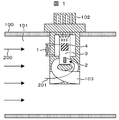
- FIG. 1 Schematic structure of fluid measuring device.
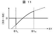
- FIG. 3 is a relationship diagram between S1 and (S3-S2) of the fluid measuring device according to the first embodiment.
- the system structural example which consists of a fluid measuring device and ECU.
- FIGS. 1, 2, 10, 11, and 14 a first embodiment, which is an embodiment of the present invention, will be described with reference to FIGS. 1, 2, 10, 11, and 14.
- a main fluid 200 can flow through the main passage 101 formed by the pipe 100, and a casing 102 is inserted into the main passage 101 in order to measure the flow rate of the main fluid 200.
- the casing 102 includes the temperature sensor 1 and is attached to the main passage 101 so that the temperature sensor 1 is exposed to the main fluid 200.
- the casing 102 includes a sub passage 103 into which a part of the main fluid 200 can be introduced.
- the flow sensor 2 is disposed so as to be exposed to the introduced branch fluid 201.
- the flow sensor 2 is supported by a support 3, and the circuit element 4 is also mounted on the support 3.
- the circuit element 4 plays a role of converting the output signal of the flow sensor 2 into flow information and outputting it to an external device.
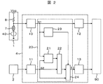
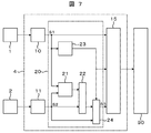
- FIG. 2 shows a detection circuit block of the fluid measuring device according to the first embodiment.
- the other end of the thermistor 7 with one end grounded is connected to one end of the fixed resistor 8, and the other end of the fixed resistor 8 is connected to a predetermined voltage Vcc.
- the analog signal at the midpoint potential of the thermistor 7 and the fixed resistor 8 is input to the circuit element 4, and the analog signal at the midpoint potential is converted into the digital signal S 1 by the AD converter 10 provided in the circuit element 4.
- the analog signal output from the flow sensor 2 is also input to the circuit element 4 and converted into a digital signal S2 by the AD converter 11 provided in the circuit element 4.
- DSP 20 digital signal processing device 20
- ECU90 electronice control unit 90
- the DSP 20 includes a correction amount calculation unit 21 that determines a correction amount for correcting S2, and determines the correction amount based on S1 and S2. This correction amount is added to S2 in the adding unit 22.
- the fluid measuring device selects either the determination unit 23 for determining the abnormality of S1, the output of the addition unit 22 or S2, and the DA converter 13 as the digital signal S3.
- a switch 24 for inputting to is added.
- the temperature sensor 1 of the fluid measuring device in the first embodiment is disposed in the main passage 101 as shown in FIG. 1 and is directly exposed to the main fluid 200. For this reason, foreign matters such as dust and oil contained in the main fluid 200 may collide with or adhere to the temperature sensor 1, and the temperature detection accuracy in the temperature sensor 1 may be reduced.
- FIG. 2 when the wiring 40 that grounds the thermistor 7 is disconnected due to the collision of a foreign substance or the like, the midpoint potential of the thermistor 7 and the fixed resistor 8 changes to Vcc. Since the change in the midpoint potential is reflected in S1, the determination unit 23 can diagnose the abnormality by detecting the change in S1.
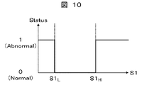
- the abnormality determination method of the determination part 23 in 1st Example is demonstrated using FIG.
- the determination unit 23 can be realized by using, for example, a window comparator.
- the determination unit 23 in the first embodiment is 0 (normal) when S1 is within a predetermined range S1 L to S1 H as shown in FIG. Is output, and 1 (abnormal) is output when deviating from the predetermined range.
- the switch 24 can select and connect the content of S3 according to the determination result of the determination unit 23 to either the output value of the addition unit 22 or S2, and in the first embodiment, the predetermined range S1 L to S1 is selected. S2 was changed to S3 outside H. For this reason, while the predetermined correction amount according to the change of S1 is added to S2 within the predetermined range to generate S3, the influence of the change of S1 on S3 can be suppressed outside the predetermined range. It is possible to prevent overcorrection processing caused by the abnormality of 1.
- S1 and S2 input to the DSP 20 are input to the correction amount calculation unit 21, and the correction amount calculation unit 21 determines a correction amount based on S1 and S2.
- S2 is input to the determination unit 23, and S1 abnormality determination is performed based on S1 L and S1 H.
- S1 is determined to be normal
- S1 is determined to be normal
- S2 is output as S3.
- the fluid measuring device has the following advantages by performing the above operations.
- the first advantage is that, in a situation where the reliability of S1 is lowered, such as when the temperature sensor 1 is damaged, the determination unit 23 can grasp the state.
- the second advantage is that the correction process by S1 can be suppressed by the switch 24 in a situation where the reliability of S1 is lowered, such as when the temperature sensor 1 is damaged.
- a third advantage is that the technology of the present invention can be applied without adding a large-scale circuit because the determination unit 23 and the switch 24 can be realized by digital signal processing by the DSP 20.
- a fourth advantage is that since the determination unit 23 and the switch 24 can be realized by digital signal processing by the DSP 20, the determination thresholds S1 L and S1 H of the determination unit 23 can be easily changed.
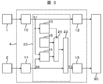
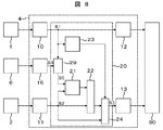
- the switch 26 selects the output of the correction amount calculation unit 21 and the fixed value output from the signal generator 25 according to the determination result of the determination unit 23 and transmits the selected value to the addition unit 22. For this reason, it becomes possible to use the fixed value output from the signal generator 25 when the temperature sensor 1 is abnormal as a correction amount, and as a result, it is possible to suppress overcorrection processing caused by the abnormality of the temperature sensor 1.
- the output value of the signal generator 25 can be manipulated to an arbitrary value, it is possible to fix the output to a value such as all 1 or all 0 in S3. Therefore, when the temperature sensor 1 is abnormal, the state notification to the external device can be performed by operating S3.
- the predetermined signal generated by the signal generator 25 may be a fixed value or a periodic pulse signal.
- a fifth advantage is that a status notification to an external device is possible when the temperature sensor 1 is abnormal.
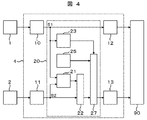
- the fluid measuring apparatus selects the output of the signal generator 25 and the output of the adder 22 in place of the switch 26 provided in the fluid measuring apparatus according to the second embodiment, and the DA converter 13.
- a switch 27 for transmitting to is added.
- the operation of the switch 27 will be described.
- the switch 27 selects the output of the adder 22 and the fixed value output from the signal generator 25 according to the determination result of the determination unit 23 and transmits the selected value to the DA converter 13. For this reason, since the fixed value output from the signal generator 25 when the temperature sensor 1 is abnormal can be used as S3, any value can be output to an external device when the temperature sensor 1 is abnormal. That is, it is possible to notify the status to an external device via S3.
- a sixth advantage is that an arbitrary value can be output to an external device when the temperature sensor 1 is abnormal.
- a fourth embodiment which is an embodiment of the present invention, will be described with reference to FIGS.
- a numerical value of S1 is provided between the AD converter 10 and the correction amount calculating unit 21 instead of the determination unit 23 and the switch 24 provided in the fluid measuring device according to the first embodiment.
- a limiter 28 for limiting the range is added.
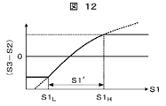
- the operation of the limiter 28 will be described with reference to FIG.
- the limiter 28 can set the limit range S1 L to S1 H of S1, and limit the numerical range of S1 input to the correction amount calculation unit 21. As a result, since the digital signal S1 ′ within the limit range is input to the correction amount calculation unit 21, even when the value of S1 changes significantly due to the abnormality of the temperature sensor 1, correction is performed. Since the correction amount to be applied can fall within a predetermined range, an error in the flow rate value due to overcorrection can be reduced.
- the necessary correction amount may differ depending on the flow rate, and in this case, there are limit ranges S1 L to S1 H suitable for each flow rate. Therefore, it is preferable that the limiter 28 can set the limit ranges S1 L to S1 H according to S2.
- the first advantage is that the error of the flow rate value due to overcorrection can be reduced by the limiter 28 in a situation where the reliability of S1 is lowered, such as when the temperature sensor 1 is broken.
- the second advantage is that the technology of the present invention can be applied without adding a large-scale circuit because the limiter 28 can be realized by digital signal processing by the DSP 20.
- the third advantage is that the limiter 28 can be realized by digital signal processing by the DSP 20, so that the limit range of the limiter 28 can be easily changed.
- the fluid measurement device according to the first modification example includes a DA converter 14 that converts the determination result of the determination unit 23 provided in the fluid measurement device according to the first embodiment into an analog signal, and the determination result of the determination unit 23 is obtained. It is possible to transmit directly to the ECU 90. Thereby, the abnormality of the temperature sensor 1 can be detected by the ECU 90.
- the fluid measuring device includes a communication interface 15 in place of the DA converter 12 and the DA converter 13 provided in the fluid measuring device according to the first embodiment, and together with S1 and S3, a determination unit It is possible to digitally output 23 determination result signals. Thereby, several detection information can be transmitted to ECU90 with a single digital communication bus.
- the fluid measurement device includes a temperature sensor 6 in the fluid measurement device according to the first embodiment, an AD converter 16 that digitally converts the output of the temperature sensor 6, and a digital signal output by the AD converter 16.
- a calculation unit 29 that outputs a difference signal S5 between S4 and S1 is added, and the correction amount calculation unit 21 derives a correction amount based on S2 and S5.
- a determination unit for determining S4 may be added to the fluid measuring device according to the third modification, and the switch 24 may be operated when one of S1 and S4 is determined to be abnormal. Thereby, further excellent reliability can be ensured.
- the fluid measurement device selects either the signal generator 30 or the output of the signal generator 30 or S1 according to the determination result of the determination unit 23 in the fluid measurement device according to the first embodiment. Then, a switch 31 for inputting to the DA converter 12 is added. Thereby, it becomes possible to output the predetermined signal generated by the signal generator 30 to the ECU 90 via the DA converter 12 instead of S1 when the temperature sensor 1 is abnormal.
- the predetermined signal generated by the signal generator 30 may be a fixed value or a periodic pulse signal.
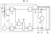
- FIG. 13 shows a configuration for determining abnormality of the temperature sensor 1 on the ECU 90 side when the fluid measuring device and the ECU 90 are combined. That is, the sensor device 5 does not have a state determination unit for the temperature sensor 1 inside.
- the detection signal of the temperature sensor 1 output from the circuit element 4 is input to the ECU 90 via the harness 41, and then input to the determination unit 94 provided in the ECU 90 to determine abnormality.
- the ECU 90 includes switches 91 and 92 before the detection signals of the temperature sensor 1 and the flow sensor 2 output from the circuit element 4 are input to the signal processing unit 93, and intermittent control is performed according to the determination result of the determination unit 94. I do.
- the fourth modification a periodic pulse signal generated by the signal generator 30 when the temperature sensor 1 is abnormal can be output to the ECU 90 via the switch 31. Therefore, the first advantage of the fluid measuring device according to the fourth modification is that it is possible to distinguish between when the temperature sensor 1 is damaged and when the harness 41 is disconnected. Further, in the failure mode in which the harness 41 is disconnected, the DSP 20 appropriately performs the correction operation. Accordingly, the second advantage is that the ECU 90 can use the detection signal of the flow sensor 2 even in the failure mode in which the harness 41 is disconnected.
- the operation has been explained for correcting the output of the flow sensor with the output of the temperature sensor.
- the output of the flow sensor is corrected with the output of the pressure sensor
- the output of the humidity sensor is changed to the temperature sensor. It can be applied to the case of correcting with the output of.
- the combination of temperature sensors may be sufficient and it is not limited to the combination of the sensor quoted in the Example.
Landscapes
- Physics & Mathematics (AREA)
- Fluid Mechanics (AREA)
- General Physics & Mathematics (AREA)
- Measuring Volume Flow (AREA)
- Details Of Flowmeters (AREA)
- Measuring Temperature Or Quantity Of Heat (AREA)
Abstract
Description
V=v+ΔX(v,t)・(t-t0)
として、パラメータvを基準温度t0における流量に補正する補正手段を有するものである。
V=v+ΔY(v,p)・(p-p0)
として、パラメータvを基準圧力p0における流量に補正する補正手段を有するものである。
配管100により形成した主通路101の中は主流体200が通流可能であり、この主流体200の流量を測定するため主通路101にケーシング102を挿入する。ケーシング102は温度センサ1を備えており、温度センサ1が主流体200にさらされるように主通路101に取り付けられる。また、ケーシング102は主流体200の一部を導入可能な副通路103を備えている。副通路103の内部には、導入した支流体201にさらすように流量センサ2を配置する。流量センサ2は支持体3により支持し、支持体3には回路素子4も搭載する。回路素子4は流量センサ2の出力信号を流量情報に変換して外部機器に出力する役割を担う。
第3実施例をなす流体計測装置は、第2実施例をなす流体計測装置に設けたスイッチ26に代えて、信号発生器25の出力と加算部22の出力とを選択してDA変換器13に伝達するスイッチ27を追加したことを特徴とする。以下、スイッチ27の動作を解説する。
第4実施例をなす流体計測装置は、第1実施例をなす流体計測装置に設けた判定部23およびスイッチ24に代えて、AD変換器10と補正量演算部21との間にS1の数値範囲を限定するリミッタ28を追加したことを特徴とする。以下、リミッタ28の動作を、図12を用いて解説する。
第1変形例をなす流体計測装置は、第1実施例をなす流体計測装置に設けた判定部23の判定結果をアナログ信号に変換するDA変換器14を追加し、判定部23の判定結果をECU90に直接伝送できるようにしたことを特徴とする。これにより、温度センサ1の異常をECU90で検知することができる。
第2変形例をなす流体計測装置は、第1実施例をなす流体計測装置に設けたDA変換器12、DA変換器13に代えて、通信インターフェース15を追加し、S1およびS3と共に、判定部23の判定結果の信号をデジタル出力できるようにしたことを特徴とする。これにより、単一のデジタル通信バスでECU90へ複数の検出情報を伝送することができる。
第3変形例をなす流体計測装置は、第1実施例をなす流体計測装置に温度センサ6と、温度センサ6の出力をデジタル変換するAD変換器16と、AD変換器16が出力するデジタル信号S4とS1との差分信号S5を出力する演算部29を追加し、補正量演算部21はS2およびS5に基づいて補正量を導出する事を特徴とする。
第4変形例をなす流体計測装置は、第1実施例をなす流体計測装置に信号発生器30と、判定部23の判定結果に応じて信号発生器30の出力またはS1のいずれか一方を選択してDA変換器12に入力するスイッチ31を追加したことを特徴とする。これにより、温度センサ1の異常時にはS1に代えて、信号発生器30で生成した所定信号をDA変換器12を介してECU90に出力することが可能となる。尚、信号発生器30によって生成する所定信号は固定値でも良いし、周期的なパルス信号でも良い。
2 流量センサ
3 支持体
4 回路素子
5 センサ装置
7 サーミスタ
8 固定抵抗
10,11,16 AD変換器
12~14 DA変換器
15 通信インターフェース
20 デジタル信号処理装置(DSP)
21 補正量演算部
22 加算部
23 判定部
24,26,27,31,91,92 スイッチ
25,30 信号発生器
28 リミッタ
29 演算部
40 配線
41 ハーネス
90 ECU
93 信号処理部
94 判定部
100 配管
101 主通路
102 ケーシング
103 副通路
200 主流体
201 支流体
Claims (14)
- 第1検出素子から出力される第1信号および第2検出素子から出力される第2信号が入力される回路部を有する、流体計測装置であって、
前記回路部は、
前記第1信号および前記第2信号に応じた第3信号を出力する信号処理手段と、
前記第1信号の状態を判定する状態判定手段と、
前記状態判定手段の判定結果に応じて前記第1信号の変化が前記第3信号に与える変化の量を制御する制御手段と、を備える流体計測装置。 - 請求項1に記載の流体計測装置において、
前記制御手段は、
前記状態判定手段の判定結果において、前記第1信号が正常状態であると示す範囲では、前記第1信号の変化量と前記第2信号と前記第3信号との差分の変化量との相関係数が一定または連続的に変化する関係となる様に前記第3信号に与える変化の量を制御し、
前記状態判定手段の判定結果において、前記第1信号が正常状態であると示す範囲から外れた際に、前記第1信号の変化量と前記第2信号と前記第3信号との差分の変化量との相関係数が非連続的に変化する様に前記第3信号に与える変化の量を制御する流体計測装置。 - 請求項1または2に記載の流体計測装置において、
前記制御手段は、前記第1信号の変化が前記第3信号に与える変化の量に上限を設ける手段を備える流体計測装置。 - 請求項1または2に記載の流体計測装置において、
前記制御手段は、前記第1信号の変化が前記第3信号に与える変化の量に下限を設ける手段を備える流体計測装置。 - 請求項1または2に記載の流体計測装置において、
前記制御手段は、前記第1信号の変化が前記第3信号に与える変化の量に上限および下限を設ける手段を備える流体計測装置。 - 請求項1または2に記載の流体計測装置において、
前記制御手段は、前記第1信号の変化が前記第3信号に与える変化の量をゼロとする無効化手段を備える流体計測装置。 - 請求項6に記載の流体計測装置において、
前記無効化手段は、前記第2信号を前記第3信号とする手段を備える流体計測装置。 - 請求項6に記載の流体計測装置において、
前記無効化手段は、所定値を前記第3信号とする手段を備える流体計測装置。 - 請求項1または2に記載の流体計測装置において、
前記状態判定手段は、前記第1信号が所定値よりも大きい場合に異常と判定する手段を備える流体計測装置。 - 請求項1または2に記載の流体計測装置において、
前記状態判定手段は、前記第1信号が所定値よりも小さい場合に異常と判定する手段を備える流体計測装置。 - 請求項1または2に記載の流体計測装置において、
前記状態判定手段は、前記第1信号が所定の範囲から逸脱した場合に異常と判定する手段を備える流体計測装置。 - 請求項1または2に記載の流体計測装置において、
前記状態判定手段の判定結果を外部に通知する通知手段を備える流体計測装置。 - 請求項12に記載の流体計測装置において、
前記通知手段は、所定の通信手段を備える流体計測装置。 - 請求項1または2に記載の流体計測装置において、
前記第1検出素子は、流体の温度を検出する素子であり、
前記第2検出素子は、流体の流量を検出する素子である流体計測装置。
Priority Applications (5)
| Application Number | Priority Date | Filing Date | Title |
|---|---|---|---|
| JP2014522278A JP5853102B2 (ja) | 2012-06-27 | 2012-06-27 | 流体計測装置 |
| PCT/JP2012/066317 WO2014002198A1 (ja) | 2012-06-27 | 2012-06-27 | 流体計測装置 |
| CN201280074363.9A CN104412076B (zh) | 2012-06-27 | 2012-06-27 | 流体测量装置 |
| US14/411,346 US9574925B2 (en) | 2012-06-27 | 2012-06-27 | Fluid measurement device having a circuit for precise flow measurement |
| DE112012006615.4T DE112012006615T5 (de) | 2012-06-27 | 2012-06-27 | Fluidmessvorrichtung |
Applications Claiming Priority (1)
| Application Number | Priority Date | Filing Date | Title |
|---|---|---|---|
| PCT/JP2012/066317 WO2014002198A1 (ja) | 2012-06-27 | 2012-06-27 | 流体計測装置 |
Publications (1)
| Publication Number | Publication Date |
|---|---|
| WO2014002198A1 true WO2014002198A1 (ja) | 2014-01-03 |
Family
ID=49782430
Family Applications (1)
| Application Number | Title | Priority Date | Filing Date |
|---|---|---|---|
| PCT/JP2012/066317 Ceased WO2014002198A1 (ja) | 2012-06-27 | 2012-06-27 | 流体計測装置 |
Country Status (5)
| Country | Link |
|---|---|
| US (1) | US9574925B2 (ja) |
| JP (1) | JP5853102B2 (ja) |
| CN (1) | CN104412076B (ja) |
| DE (1) | DE112012006615T5 (ja) |
| WO (1) | WO2014002198A1 (ja) |
Cited By (1)
| Publication number | Priority date | Publication date | Assignee | Title |
|---|---|---|---|---|
| JP2016223855A (ja) * | 2015-05-28 | 2016-12-28 | 株式会社デンソー | 空気流量測定装置 |
Families Citing this family (4)
| Publication number | Priority date | Publication date | Assignee | Title |
|---|---|---|---|---|
| JP6021761B2 (ja) * | 2013-08-27 | 2016-11-09 | 日立オートモティブシステムズ株式会社 | ガスセンサ装置 |
| SG2013084009A (en) * | 2013-11-12 | 2015-06-29 | Rockwell Automation Asia Pacific Business Ctr Pte Ltd | Multiple alternative automation input system and method |
| JP6142840B2 (ja) * | 2014-04-28 | 2017-06-07 | 株式会社デンソー | 空気流量測定装置 |
| CN117157507A (zh) * | 2021-04-27 | 2023-12-01 | 日立安斯泰莫株式会社 | 物理量检测装置、信号处理装置和信号处理方法 |
Citations (3)
| Publication number | Priority date | Publication date | Assignee | Title |
|---|---|---|---|---|
| JPS5331160A (en) * | 1976-09-03 | 1978-03-24 | Hitachi Ltd | Automatic switching circuit for temperature correction operational circuit |
| JPH1038657A (ja) * | 1996-07-29 | 1998-02-13 | Osaka Gas Co Ltd | 流量補正装置 |
| JP2001241990A (ja) * | 2000-03-02 | 2001-09-07 | Kimmon Mfg Co Ltd | 流量測定装置 |
Family Cites Families (5)
| Publication number | Priority date | Publication date | Assignee | Title |
|---|---|---|---|---|
| US6517508B1 (en) * | 1999-11-03 | 2003-02-11 | Dsu Medical Corporation | Set for blood processing |
| CN1249406C (zh) * | 2000-09-04 | 2006-04-05 | 株式会社日立制作所 | 热式空气流量计 |
| JP4269046B2 (ja) | 2002-08-29 | 2009-05-27 | 東京瓦斯株式会社 | 流量計 |
| CN101057126B (zh) * | 2004-11-11 | 2010-10-06 | 株式会社日立制作所 | 热式流量测定装置 |
| JP5284864B2 (ja) * | 2009-04-30 | 2013-09-11 | 日立オートモティブシステムズ株式会社 | 熱式空気流量計 |
-
2012
- 2012-06-27 CN CN201280074363.9A patent/CN104412076B/zh active Active
- 2012-06-27 WO PCT/JP2012/066317 patent/WO2014002198A1/ja not_active Ceased
- 2012-06-27 DE DE112012006615.4T patent/DE112012006615T5/de active Pending
- 2012-06-27 US US14/411,346 patent/US9574925B2/en active Active
- 2012-06-27 JP JP2014522278A patent/JP5853102B2/ja active Active
Patent Citations (3)
| Publication number | Priority date | Publication date | Assignee | Title |
|---|---|---|---|---|
| JPS5331160A (en) * | 1976-09-03 | 1978-03-24 | Hitachi Ltd | Automatic switching circuit for temperature correction operational circuit |
| JPH1038657A (ja) * | 1996-07-29 | 1998-02-13 | Osaka Gas Co Ltd | 流量補正装置 |
| JP2001241990A (ja) * | 2000-03-02 | 2001-09-07 | Kimmon Mfg Co Ltd | 流量測定装置 |
Cited By (1)
| Publication number | Priority date | Publication date | Assignee | Title |
|---|---|---|---|---|
| JP2016223855A (ja) * | 2015-05-28 | 2016-12-28 | 株式会社デンソー | 空気流量測定装置 |
Also Published As
| Publication number | Publication date |
|---|---|
| CN104412076B (zh) | 2017-06-13 |
| JPWO2014002198A1 (ja) | 2016-05-26 |
| DE112012006615T5 (de) | 2015-03-26 |
| JP5853102B2 (ja) | 2016-02-09 |
| US9574925B2 (en) | 2017-02-21 |
| CN104412076A (zh) | 2015-03-11 |
| US20150377676A1 (en) | 2015-12-31 |
Similar Documents
| Publication | Publication Date | Title |
|---|---|---|
| US10606228B2 (en) | Measurement transducer having a monitoring function | |
| JP5853102B2 (ja) | 流体計測装置 | |
| US10003864B2 (en) | Device for transmitting and receiving a sensor signal | |
| JP2009526995A (ja) | プロセス変量トランスミッタにおける多相オーバーリーディング補正 | |
| CN102749135B (zh) | 用于在流体中测量超声波信号的渡越时间的方法和装置 | |
| CN107218955B (zh) | 现场设备以及检测器 | |
| CN103454485B (zh) | 过程控制回路电流验证 | |
| JP5998504B2 (ja) | 流量計および流量計の診断方法 | |
| JP7359949B2 (ja) | 圧電変換器の状態監視 | |
| JP2013088399A (ja) | 流量計、流量計の制御プログラム、および流量計の制御方法 | |
| EP2745284B1 (en) | Two-wire process control loop current diagnostics | |
| JP6329648B2 (ja) | 故障検出装置 | |
| US9389629B2 (en) | Measuring arrangement for determining a measured variable and method for generating an output signal relating to the measured variable | |
| US10557745B2 (en) | Electromagnetic flow meter and miswiring detection method | |
| US11959783B2 (en) | Field device | |
| CN102052944A (zh) | 科里奥利质量流量计 | |
| JP5584634B2 (ja) | 角速度検出装置及び角速度のエラー検出方法 | |
| JP2011033439A (ja) | コリオリ質量流量計 | |
| JP5040719B2 (ja) | 2線式フィールド機器とフィールドバスシステム | |
| JP4345207B2 (ja) | 力学量検出センサ | |
| JP2004205283A (ja) | 流体流量検知装置 | |
| JPH06189372A (ja) | 計装用インタフェース | |
| KR101188721B1 (ko) | 기준유량계의 신호를 직접 입력받아 교정대상 유량계의 교정이 가능한 시스템 | |
| RU2575693C2 (ru) | Диагностика тока двухпроводного контура управления процессом | |
| JP2012047545A (ja) | ガス濃度測定装置 |
Legal Events
| Date | Code | Title | Description |
|---|---|---|---|
| 121 | Ep: the epo has been informed by wipo that ep was designated in this application |
Ref document number: 12880193 Country of ref document: EP Kind code of ref document: A1 |
|
| ENP | Entry into the national phase |
Ref document number: 2014522278 Country of ref document: JP Kind code of ref document: A |
|
| WWE | Wipo information: entry into national phase |
Ref document number: 14411346 Country of ref document: US |
|
| WWE | Wipo information: entry into national phase |
Ref document number: 112012006615 Country of ref document: DE Ref document number: 1120120066154 Country of ref document: DE |
|
| 122 | Ep: pct application non-entry in european phase |
Ref document number: 12880193 Country of ref document: EP Kind code of ref document: A1 |