EP2745284B1 - Two-wire process control loop current diagnostics - Google Patents
Two-wire process control loop current diagnostics Download PDFInfo
- Publication number
- EP2745284B1 EP2745284B1 EP12751650.8A EP12751650A EP2745284B1 EP 2745284 B1 EP2745284 B1 EP 2745284B1 EP 12751650 A EP12751650 A EP 12751650A EP 2745284 B1 EP2745284 B1 EP 2745284B1
- Authority
- EP
- European Patent Office
- Prior art keywords
- signal
- analog
- converter
- output
- loop
- Prior art date
- Legal status (The legal status is an assumption and is not a legal conclusion. Google has not performed a legal analysis and makes no representation as to the accuracy of the status listed.)
- Active
Links
- 238000004886 process control Methods 0.000 title claims description 15
- 238000000034 method Methods 0.000 claims description 43
- 230000004044 response Effects 0.000 claims description 4
- 238000012795 verification Methods 0.000 claims 1
- 238000010586 diagram Methods 0.000 description 11
- 230000001276 controlling effect Effects 0.000 description 4
- 238000012544 monitoring process Methods 0.000 description 4
- 238000004891 communication Methods 0.000 description 3
- 230000006870 function Effects 0.000 description 3
- 230000003750 conditioning effect Effects 0.000 description 2
- 238000012369 In process control Methods 0.000 description 1
- 230000005540 biological transmission Effects 0.000 description 1
- 238000006243 chemical reaction Methods 0.000 description 1
- 230000001419 dependent effect Effects 0.000 description 1
- 230000000694 effects Effects 0.000 description 1
- 238000010965 in-process control Methods 0.000 description 1
- 238000010978 in-process monitoring Methods 0.000 description 1
- 230000001105 regulatory effect Effects 0.000 description 1
Images

Classifications
-
- G—PHYSICS
- G08—SIGNALLING
- G08C—TRANSMISSION SYSTEMS FOR MEASURED VALUES, CONTROL OR SIMILAR SIGNALS
- G08C25/00—Arrangements for preventing or correcting errors; Monitoring arrangements
Definitions
- the present disclosure relates to process variable transmitters used in process control and monitoring systems. More specifically, the present disclosure relates to performing loop current diagnostics to identify on-scale errors in the loop current of a transmitter.
- Process variable transmitters are used to measure process parameters (or process variables) in a process control or monitoring system.
- Microprocessor-based transmitters often include a sensor, an analog-to-digital converter for converting an output from the sensor into a digital form, a microprocessor for compensating the digitized output, and an output circuit for transmitting a compensated output.
- this transmission is normally done over a process control loop, such as a 4-20 milliamp control loop, or wirelessly.
- control loop is controlled by a loop current regulator.
- a loop current regulator regulates the loop current to reflect process variables sensed by the sensors in the instrument.
- US 2005/0149295 (A1 ) relates to a transmitter and in particular a monitoring unit which compares an output signal taken from across a resistance located in an output branch with an auxiliary signal derived from a raw signal are coming from a pre-processor which converts the electrical quantity measured from a physical parameter into the raw signal.
- the monitoring unit effects safety-directed adjustment of the output signal, when a difference between the output signal and the raw signal exceeds a predetermined level.
- a process variable transmitter controls a signal on a communication loop.
- a diagnostic component on the transmitter compares an expected signal level on the communication loop with an actual value to detect on-scale errors.
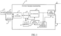
- FIG. 1 is a simplified block diagram of a transmitter 10 in accordance with one embodiment.
- Transmitter 10 in the embodiment shown in FIG. 1 , includes analog-to-digital (A/D) converter 12, processor 14, clock and memory circuitry 16, digital-to-analog converter 18, loop control component 20 and loop current diagnostic component 22.
- Transmitter 10 is shown coupled to a plurality of different process variable (PV) sensors 24 and 26.
- Transmitter 10 may also illustratively be coupled to a host system or control room (not shown) over control loop 28.
- Transmitter 10 could be connected to a wireless communication link in addition to process control loop 28.
- process control loop 28 provides power to transmitter 10 as well.
- Sensors 24 and 26 are illustratively process variable sensors that receive inputs from process 30 that is being sensed.
- sensor 24 may illustratively be a thermocouple that senses temperature and sensor 26 may be either the same or a different type of sensor, such as a flow sensor.
- Other PV sensors can include a variety of sensors, such as pressure sensors, pH sensors, etc.
- Sensors 24 and 26 illustratively provide an output that is indicative of a sensed process variable to A/D converter 12.
- Conditioning logic can also be included (but is now shown) for amplifying, linearizing, and otherwise conditioning the signals provided by sensors 24 and 26.
- A/D converter 12 receives signals indicative of the process variables sensed by sensors 24 and 26.
- A/D converter 12 converts the analog signals into digital signals and provides them to processor 14.
- processor 14 is a computer microprocessor or microcontroller that has associated memory and clock circuitry 16 and provides digital information indicative of the sensed process variables to D/A converter 18.
- D/A converter 18 illustratively converts the signals indicative of process variables into analog signals that are provided to loop control component 20, in order to control the current (I) on loop 28.
- Loop control component 20 can provide the information over control loop 28 either in digital format (such as by using the HART protocol), or in analog format (or both) by controlling current (I) through loop 28.
- the information related to the sensed process variables is provided over process control loop 28 by transmitter 10.
- D/A converter 18 also provides an input to loop current diagnostic component 22. Signals output by D/A converter 18 are indicative of a desired loop current (I). That is, the signal output by D/A converter 18 is illustratively indicative of a loop current (I) which will reflect the value of the sensed process variable. Based on the signal provided by D/A converter 18, loop control component 20 illustratively controls loop 28 such that current (I) indicates the signal output by D/A converter 18.
- loop control component 20 is controlling the loop current (I) on loop 28 accurately, especially where an error in the loop current is an on-scale error.
- the loop current varies, on-scale, between 4 and 20 milliamps (that is, it varies, between an on-scale minimum value and an on-scale maximum value of 4 and 20 milliamps, respectively).
- on-scale errors incorrect readings between 4 and 20 milliamps can occur.
- FIG. 1 shows that transmitter 10 also includes loop current diagnostic component 22.
- the output of D/A converter 18 is provided to diagnostic component 22, as is an indication from loop control component 20 that indicates the level of the actual loop current flowing on loop 28.
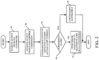
- FIG. 2 is a flow diagram illustrating how loop current diagnostic component 22 operates, in accordance with one embodiment, to identify on-scale errors in control loop 28.
- Diagnostic component 22 first receives the output from D/A converter 18. This is indicated by block 40 in FIG. 2 . Diagnostic component 22 also receives the output from loop control component 20. This is indicated by block 42 in FIG. 2 . The signal output from D/A converter 18 and that output from loop control component 20 are indicative of the desired and actual loop current values, respectively. Thus, loop current diagnostic component 22 compares the expected (or desired) and actual loop current values as illustrated by block 44 in FIG. 2 . If the two values are sufficiently close, then loop current control component 20 is accurately controlling the current on loop 28 based on the output of D/A converter 18. This is indicated by blocks 46 and 48 in FIG. 2 .
- loop current diagnostic component 22 generates and sends an error indicator 50 to processor 14 and/or D/A converter 18, asserting an alarm condition. This is indicated by block 52 in FIG. 2 .
- current diagnostic component 22 illustratively compares the two signals to determine whether they are within a predetermined threshold value of one another. If so, then they are sufficiently close. Otherwise, they are not close enough and the error indicator 50 is generated.
- the particular threshold value can be set empirically, or in another way, and may vary based on the application, based on the particular control loop being used, or based on other factors. In one embodiment, it may be set to 100 microamps.
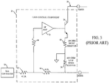
- FIG. 3 illustrates a partial block diagram and partial schematic diagram showing a conventional loop control component 20. It can be seen that loop control component 60 includes resistors 62, 64, 66, 68, and 70, operational amplifier 72, and transistor 74.
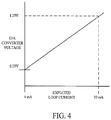
- D/A converter 18 provides an analog output voltage that varies linearly in proportion to the desired loop current on loop 28.
- D/A converter 18 illustratively provides, at its output, 0.25 volts when the loop current on loop 28 is desired to be 4 milliamps, and 1.25 volts when the loop current on loop 28 is desired to be 20 milliamps.
- FIG. 4 illustrates this graphically. It can be seen from FIG. 4 that as the expected loop current varies between 4 milliamps and 20 milliamps, the output voltage from D/A converter 18 varies linearly, between 0.25 volts and 1.25 volts.
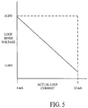
- loop control component 20 illustratively controls the loop current by measuring the voltage across a precision resistor 70, which may illustratively be 49.9 ohms. It can be seen from FIG. 3 that the voltage developed across resistor 70 is negative with respect to circuit ground. It can also be seen that, based on the values of resistors 62, 66, 68 and 70, voltage across precision resistor 70 will illustratively vary, linearly, between -0.20 volts and -1.00 volts. FIG. 5 shows this graphically. It can be seen from FIG. 5 that as the loop voltage across precision resistor 70 varies between -0.20 volts and -1.00 volts, the actual loop current flowing on loop 28 varies between 4 milliamps and 20 milliamps.
- FIG. 6 shows a graph of both the voltage output by D/A converter 18 and the loop voltage across resistor 70 when the loop voltage shown in FIG. 5 has been inverted and multiplied by a scale factor of 1.25. Because the voltage output by D/A converter 18 (shown by numeral 90 in FIG. 6 ) represents the desired or expected loop current, and because the loop voltage across resistor 70 (indicated by 92 in FIG. 6 ) represents the actual loop current, on-scale errors can be identified by simply comparing the two values shown in FIG. 6 . This, effectively, compares desired or expected loop current against actual loop current.
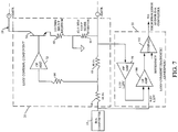
- FIG. 7 illustrates one embodiment of loop control component 20 and loop current diagnostic component 22 for performing this type of comparison. It will be noted, of course, that the embodiment shown in FIG. 7 is only one illustrative embodiment and a wide variety of other circuits could be used to compare the two values as well. However, the embodiment shown in FIG. 7 is one relatively inexpensive and accurate way for comparing the two values and providing a signal to processor 14 and/or D/A converter 18 that indicates when an error has occurred.
- loop control component 20 includes some elements which are similar to those shown in FIG. 3 , and similar elements are similarly numbered. It can also be seen that resistors 62 and 70 have been replaced by resistors 94 and 96. The values of resistors 94 and 96 have been chosen to scale the voltage developed across resistor 96 by the loop current flowing on loop 28 by a factor of 1.25 (or by any other factor to make it substantially equal in magnitude to the voltage output by D/A converter 18).
- Loop current diagnostic component 22 illustratively includes operational amplifiers 98, 100 and 102.
- Operational amplifier 98 is configured as an inverter such that the voltage developed across resistor 96 is inverted relative to circuit ground to have the same polarity as the voltage output by D/A converter 18. It can be seen that, in the embodiment shown in FIG. 7 , the (now scaled) on-scale voltage across resistor 96 will vary from -0.25 volts to -1.25 volts. Therefore, the output of operational amplifier 98 varies from 0.25 volts to 1.25 volts.
- Operational amplifier 100 is connected as a differential operational amplifier. It therefore compares the voltage output by D/A converter 18 (which also varies on-scale from 0.25 volts to 1.25 volts) to the output of operational amplifier 98. The two values should be substantially the same. If they are not, then loop control component 20 is not accurately controlling the loop current on loop 28 to reflect the output of D/A converter 18. However, because the two signals received by operational amplifier 100 may not be identical, but may still be sufficiently close to one another, comparator 102 is also provided. Comparator 102 compares the output of operational amplifier 100 (which reflects the difference between its two input signals) to a reference or threshold value. The output of comparator 102 will thus provide the error indicator 50 to processor 14 and/or D/A converter 18 only if the difference between the two signals provided at the input of operational amplifier 100 differ by a magnitude that is greater than the reference value input to operational amplifier 102.
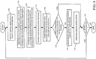
- FIG. 8 is a flow diagram illustrating the operation of the system shown in FIGS. 1 and 7 in accordance with one embodiment.
- FIG. 8 starts with processor 14 outputting the signal indicative of the process variable to D/A converter 18. This is indicated by block 120 in FIG. 8 .
- D/A converter 18 then performs a digital-to-analog conversion and outputs an analog D/A converter voltage to loop control component 20 and to diagnostic component 22. This is indicated by block 122 in FIG. 8 .
- the loop control component 20 then controls the loop current on loop 28 based on the voltage developed across resistor 96. This is indicated by block 124 in FIG. 8 .
- Loop control component 20 also, by virtue of the resistor values, scales the loop voltage across resistor 96 and provides it to loop current diagnostic component 22.
- Loop current diagnostic component 22 inverts the scaled voltage and compares it to the voltage output by D/A converter 18. This is indicated by blocks 126 and 128 in FIG. 8 .
- Loop current diagnostic component 22 determines whether the compared voltages are sufficiently close (using operational amplifier 100 and comparator 102). This is indicated by block 130 in FIG. 8 . If the two are sufficiently close, then the system simply keeps monitoring the output of D/A converter 18 and the loop current on loop 28. This is indicated by block 132.
- loop current diagnostic component 22 sends the error indicator 50 to processor 14 and/or D/A converter 18. This is indicated by block 134 in FIG. 8 .
- Processor 14 can then perform any number of error operations, as indicated by block 136. For instance, processor 14 can perform numerous tasks, such as resetting D/A converter 18 to verify that the error is actually occurring. Processor 14 can also assert an alarm or perform additional diagnostics. Processor 14 can also perform any other desired operations in response to receiving the error indicator 50 from loop current diagnostic component 22.
- loop current diagnostic component 22 and loop control component 20 can all be performed by a single component, or the functions can be allocated between those components (or among other components in transmitter 10) in different ways.
- values have been given for certain resistors, voltages and currents, other values can be used as well. Those, given are exemplary only.
- certain components op amps, resistive elements, resistor, etc. are identified in FIG. 7 , they are identified by way of example only. The same function of scaling and inverting either the loop or D/A converter voltage and comparing the two can be accomplished in many different ways, with different circuits, other than that shown in FIG. 7 .
Description
- The present disclosure relates to process variable transmitters used in process control and monitoring systems. More specifically, the present disclosure relates to performing loop current diagnostics to identify on-scale errors in the loop current of a transmitter.
- Process variable transmitters are used to measure process parameters (or process variables) in a process control or monitoring system. Microprocessor-based transmitters often include a sensor, an analog-to-digital converter for converting an output from the sensor into a digital form, a microprocessor for compensating the digitized output, and an output circuit for transmitting a compensated output. Currently, this transmission is normally done over a process control loop, such as a 4-20 milliamp control loop, or wirelessly.
- Typically, in a 4-20 milliamp process instrument, the control loop is controlled by a loop current regulator. A loop current regulator regulates the loop current to reflect process variables sensed by the sensors in the instrument.
-
US 2005/0149295 (A1 ) relates to a transmitter and in particular a monitoring unit which compares an output signal taken from across a resistance located in an output branch with an auxiliary signal derived from a raw signal are coming from a pre-processor which converts the electrical quantity measured from a physical parameter into the raw signal. The monitoring unit effects safety-directed adjustment of the output signal, when a difference between the output signal and the raw signal exceeds a predetermined level. - A process variable transmitter controls a signal on a communication loop. A diagnostic component on the transmitter compares an expected signal level on the communication loop with an actual value to detect on-scale errors. The present invention is set forth and characterized in the independent claims, while the dependent claims describe other characteristics of the invention or variants to the main inventive idea.
-
-
FIG. 1 is a simplified block diagram of a process variable transmitter coupled to a host system and sensors in a process. -
FIG. 2 is a flow diagram illustrating one embodiment of the operation of a loop current diagnostic component shown inFIG. 1 . -
FIG. 3 is a schematic diagram illustrating one embodiment of a loop current control component. -
FIG. 4 is a graph showing one embodiment of loop current plotted against digital-to-analog converter voltage. -
FIG. 5 is a graph of one embodiment showing loop current plotted against loop sense voltage. -
FIG. 6 is a graph showing one illustrative embodiment of loop current plotted against both digital-to-analog converter voltage and inverted and scaled loop sense voltage. -
FIG. 7 is a partial block diagram, partial schematic diagram of another embodiment of a loop control component. -
FIG. 8 is a flow diagram illustrating one embodiment of the operation the system shown inFIGS. 1 and7 . -
FIG. 1 is a simplified block diagram of atransmitter 10 in accordance with one embodiment.Transmitter 10, in the embodiment shown inFIG. 1 , includes analog-to-digital (A/D)converter 12,processor 14, clock andmemory circuitry 16, digital-to-analog converter 18,loop control component 20 and loop currentdiagnostic component 22.Transmitter 10 is shown coupled to a plurality of different process variable (PV)sensors Transmitter 10 may also illustratively be coupled to a host system or control room (not shown) overcontrol loop 28.Transmitter 10 could be connected to a wireless communication link in addition toprocess control loop 28. In one embodiment,process control loop 28 provides power totransmitter 10 as well. -
Sensors process 30 that is being sensed. For example,sensor 24 may illustratively be a thermocouple that senses temperature andsensor 26 may be either the same or a different type of sensor, such as a flow sensor. Other PV sensors can include a variety of sensors, such as pressure sensors, pH sensors, etc.Sensors D converter 12. - Conditioning logic can also be included (but is now shown) for amplifying, linearizing, and otherwise conditioning the signals provided by
sensors D converter 12 receives signals indicative of the process variables sensed bysensors D converter 12 converts the analog signals into digital signals and provides them toprocessor 14. - In one embodiment,
processor 14 is a computer microprocessor or microcontroller that has associated memory andclock circuitry 16 and provides digital information indicative of the sensed process variables to D/A converter 18. D/Aconverter 18 illustratively converts the signals indicative of process variables into analog signals that are provided to loopcontrol component 20, in order to control the current (I) onloop 28.Loop control component 20 can provide the information overcontrol loop 28 either in digital format (such as by using the HART protocol), or in analog format (or both) by controlling current (I) throughloop 28. In any case, the information related to the sensed process variables is provided overprocess control loop 28 bytransmitter 10. - In one embodiment, D/
A converter 18 also provides an input to loop currentdiagnostic component 22. Signals output by D/A converter 18 are indicative of a desired loop current (I). That is, the signal output by D/A converter 18 is illustratively indicative of a loop current (I) which will reflect the value of the sensed process variable. Based on the signal provided by D/A converter 18,loop control component 20illustratively controls loop 28 such that current (I) indicates the signal output by D/A converter 18. - It can be helpful to determine whether
loop control component 20 is controlling the loop current (I) onloop 28 accurately, especially where an error in the loop current is an on-scale error. In other words, in a 4-20 milliamp process control loop, the loop current varies, on-scale, between 4 and 20 milliamps (that is, it varies, between an on-scale minimum value and an on-scale maximum value of 4 and 20 milliamps, respectively). However, under some conditions (such as when the instrument's operating current exceeds available current) on-scale errors (incorrect readings between 4 and 20 milliamps) can occur. For instance, if the current onloop 28 is supposed to be set at 10.0 milliamps, but it is really regulating to 12.2 milliamps, it can be helpful to detect this type of on-scale error. This type of error can occur, by way of example only, when excessive current is drawn by an integrated circuit on the circuit board ofprocess variable transmitter 10 or because of circuit board current leakage. Of course, these are examples only, and on-scale errors can occur for other reasons as well. - Therefore,
FIG. 1 shows thattransmitter 10 also includes loop currentdiagnostic component 22. In the embodiment shown inFIG. 1 , the output of D/A converter 18 is provided todiagnostic component 22, as is an indication fromloop control component 20 that indicates the level of the actual loop current flowing onloop 28.FIG. 2 is a flow diagram illustrating how loop currentdiagnostic component 22 operates, in accordance with one embodiment, to identify on-scale errors incontrol loop 28. -
Diagnostic component 22 first receives the output from D/A converter 18. This is indicated byblock 40 inFIG. 2 .Diagnostic component 22 also receives the output fromloop control component 20. This is indicated byblock 42 inFIG. 2 . The signal output from D/A converter 18 and that output fromloop control component 20 are indicative of the desired and actual loop current values, respectively. Thus, loop currentdiagnostic component 22 compares the expected (or desired) and actual loop current values as illustrated byblock 44 inFIG. 2 . If the two values are sufficiently close, then loopcurrent control component 20 is accurately controlling the current onloop 28 based on the output of D/A converter 18. This is indicated byblocks FIG. 2 . - However, at
block 46, it is determined that the two signals are not sufficiently close, then loop currentdiagnostic component 22 generates and sends anerror indicator 50 toprocessor 14 and/or D/A converter 18, asserting an alarm condition. This is indicated byblock 52 inFIG. 2 . - In order to determine whether the actual and expected loop currents are sufficiently close, current
diagnostic component 22 illustratively compares the two signals to determine whether they are within a predetermined threshold value of one another. If so, then they are sufficiently close. Otherwise, they are not close enough and theerror indicator 50 is generated. The particular threshold value can be set empirically, or in another way, and may vary based on the application, based on the particular control loop being used, or based on other factors. In one embodiment, it may be set to 100 microamps. - In order to describe loop current
diagnostic component 22 in greater detail, an understanding of a conventional loop control component may be helpful.FIG. 3 illustrates a partial block diagram and partial schematic diagram showing a conventionalloop control component 20. It can be seen that loop control component 60 includesresistors operational amplifier 72, andtransistor 74. - In accordance with one embodiment, D/
A converter 18 provides an analog output voltage that varies linearly in proportion to the desired loop current onloop 28. By way of example, D/A converter 18 illustratively provides, at its output, 0.25 volts when the loop current onloop 28 is desired to be 4 milliamps, and 1.25 volts when the loop current onloop 28 is desired to be 20 milliamps.FIG. 4 illustrates this graphically. It can be seen fromFIG. 4 that as the expected loop current varies between 4 milliamps and 20 milliamps, the output voltage from D/A converter 18 varies linearly, between 0.25 volts and 1.25 volts. - In order to regulate the loop current to the value set by the output voltage from D/
A converter 18,loop control component 20 illustratively controls the loop current by measuring the voltage across aprecision resistor 70, which may illustratively be 49.9 ohms. It can be seen fromFIG. 3 that the voltage developed acrossresistor 70 is negative with respect to circuit ground. It can also be seen that, based on the values ofresistors precision resistor 70 will illustratively vary, linearly, between -0.20 volts and -1.00 volts.FIG. 5 shows this graphically. It can be seen fromFIG. 5 that as the loop voltage acrossprecision resistor 70 varies between -0.20 volts and -1.00 volts, the actual loop current flowing onloop 28 varies between 4 milliamps and 20 milliamps. - From
graphs 4 and 5, it can be seen that by inverting and scaling either the voltage output by D/A converter 18 (shown inFIG. 4 ) or the loop voltage across resistor 70 (shown inFIG. 5 ) the two are very similar. For instance,FIG. 6 shows a graph of both the voltage output by D/A converter 18 and the loop voltage acrossresistor 70 when the loop voltage shown inFIG. 5 has been inverted and multiplied by a scale factor of 1.25. Because the voltage output by D/A converter 18 (shown by numeral 90 inFIG. 6 ) represents the desired or expected loop current, and because the loop voltage across resistor 70 (indicated by 92 inFIG. 6 ) represents the actual loop current, on-scale errors can be identified by simply comparing the two values shown inFIG. 6 . This, effectively, compares desired or expected loop current against actual loop current. -
FIG. 7 illustrates one embodiment ofloop control component 20 and loop currentdiagnostic component 22 for performing this type of comparison. It will be noted, of course, that the embodiment shown inFIG. 7 is only one illustrative embodiment and a wide variety of other circuits could be used to compare the two values as well. However, the embodiment shown inFIG. 7 is one relatively inexpensive and accurate way for comparing the two values and providing a signal toprocessor 14 and/or D/A converter 18 that indicates when an error has occurred. - It can be seen in
FIG. 7 thatloop control component 20 includes some elements which are similar to those shown inFIG. 3 , and similar elements are similarly numbered. It can also be seen thatresistors 62 and 70 have been replaced byresistors 94 and 96. The values ofresistors 94 and 96 have been chosen to scale the voltage developed acrossresistor 96 by the loop current flowing onloop 28 by a factor of 1.25 (or by any other factor to make it substantially equal in magnitude to the voltage output by D/A converter 18). - Loop current
diagnostic component 22 illustratively includesoperational amplifiers Operational amplifier 98 is configured as an inverter such that the voltage developed acrossresistor 96 is inverted relative to circuit ground to have the same polarity as the voltage output by D/A converter 18. It can be seen that, in the embodiment shown inFIG. 7 , the (now scaled) on-scale voltage acrossresistor 96 will vary from -0.25 volts to -1.25 volts. Therefore, the output ofoperational amplifier 98 varies from 0.25 volts to 1.25 volts. -
Operational amplifier 100 is connected as a differential operational amplifier. It therefore compares the voltage output by D/A converter 18 (which also varies on-scale from 0.25 volts to 1.25 volts) to the output ofoperational amplifier 98. The two values should be substantially the same. If they are not, thenloop control component 20 is not accurately controlling the loop current onloop 28 to reflect the output of D/A converter 18. However, because the two signals received byoperational amplifier 100 may not be identical, but may still be sufficiently close to one another,comparator 102 is also provided.Comparator 102 compares the output of operational amplifier 100 (which reflects the difference between its two input signals) to a reference or threshold value. The output ofcomparator 102 will thus provide theerror indicator 50 toprocessor 14 and/or D/A converter 18 only if the difference between the two signals provided at the input ofoperational amplifier 100 differ by a magnitude that is greater than the reference value input tooperational amplifier 102. -
FIG. 8 is a flow diagram illustrating the operation of the system shown inFIGS. 1 and7 in accordance with one embodiment.FIG. 8 starts withprocessor 14 outputting the signal indicative of the process variable to D/A converter 18. This is indicated byblock 120 inFIG. 8 . D/A converter 18 then performs a digital-to-analog conversion and outputs an analog D/A converter voltage toloop control component 20 and todiagnostic component 22. This is indicated byblock 122 inFIG. 8 . - The
loop control component 20 then controls the loop current onloop 28 based on the voltage developed acrossresistor 96. This is indicated byblock 124 inFIG. 8 .Loop control component 20 also, by virtue of the resistor values, scales the loop voltage acrossresistor 96 and provides it to loop currentdiagnostic component 22. Loop currentdiagnostic component 22 inverts the scaled voltage and compares it to the voltage output by D/A converter 18. This is indicated byblocks FIG. 8 . Loop currentdiagnostic component 22 then determines whether the compared voltages are sufficiently close (usingoperational amplifier 100 and comparator 102). This is indicated byblock 130 inFIG. 8 . If the two are sufficiently close, then the system simply keeps monitoring the output of D/A converter 18 and the loop current onloop 28. This is indicated byblock 132. - However, if, at
block 130, it is determined that the two compared voltages are not sufficiently close to one another, then loop currentdiagnostic component 22 sends theerror indicator 50 toprocessor 14 and/or D/A converter 18. This is indicated byblock 134 inFIG. 8 .Processor 14 can then perform any number of error operations, as indicated byblock 136. For instance,processor 14 can perform numerous tasks, such as resetting D/A converter 18 to verify that the error is actually occurring.Processor 14 can also assert an alarm or perform additional diagnostics.Processor 14 can also perform any other desired operations in response to receiving theerror indicator 50 from loop currentdiagnostic component 22. - It will be appreciated that, while the disclosure has referred to illustrative embodiments, a variety of changes can be made. For example, the functions performed by loop current
diagnostic component 22 andloop control component 20 can all be performed by a single component, or the functions can be allocated between those components (or among other components in transmitter 10) in different ways. Similarly, while values have been given for certain resistors, voltages and currents, other values can be used as well. Those, given are exemplary only. In addition, while certain components (op amps, resistive elements, resistor, etc...) are identified inFIG. 7 , they are identified by way of example only. The same function of scaling and inverting either the loop or D/A converter voltage and comparing the two can be accomplished in many different ways, with different circuits, other than that shown inFIG. 7 . - In addition, while the above description has given a number of examples for process variables that can be sensed, it will of course be appreciated that a wide variety of other process variables can be sensed and processed in substantially the same way. Examples of such other process variables include pressure, level, flow or flow rate, etc. Further, while the embodiment discussed herein is given in the context of a two-wire transmitter, the present disclosure can be just as easily applied to a four-wire transmitter or any other type of transmitter as well.
- Although the present disclosure has been described with reference to illustrative embodiments, workers skilled in the art will recognize that changes may be made in form and detail without departing from the scope of the invention.
Claims (13)
- A process variable transmitter (10), comprising:a processor (14) configured to receive an input signal indicative of a sensed process variable and outputting a digital signal indicative of the input signal;a digital-to-analog (D/A) converter (18) configured to receive the digital signal and configured to convert it to an analog signal; the process variable transmitter (10) being characterized by:a loop control component (20) configured to receive the analog signal and configured to control a two-wire process control loop (28) based upon a voltage generated across a resistive element (96) coupled in series with the two-wire process control loop (28) to provide a transmitter output signal indicative of the analog signal, the transmitter output signal varying, on-scale, between a first signal level and a second signal level; anda loop diagnostic component (22) being configured to compare a first signal value indicative of the analog signal with a second signal value indicative of the transmitter output signal to determine whether the transmitter output signal includes an on-scale error and is configured to responsively output an error indicator to the processor (14);wherein the analog signal output by the D/A converter comprises an analog voltage,wherein the loop diagnostic component (22) includes an analog comparator (102) being configured to compare the analog voltage comprised in the analog signal, as the first signal value with the voltage across the resistive element (96), as the second signal value.
- The process variable transmitter (10) of claim 1 wherein the loop control component (20) regulates current on the two-wire process control loop, as the transmitter output signal, based on the voltage across the resistive element.
- The process variable transmitter (10) of claim 1 or 2 wherein the loop control component (20) includes at least one additional resistive element (94), wherein the resistive element (96) and the at least one additional resistive element (94) have values that scale either the voltage across the resistive element (96) or the analog voltage output by the D/A converter (18) so that, when the current on the two-wire process control loop (28) accurately indicates the analog signal output by the D/A converter (18), the voltage across the resistive element (96) has a magnitude substantially equal to a magnitude of the analog voltage output by the D/A converter (18).
- The process variable transmitter (10) of claim 3 wherein the loop diagnostic component (22) includes an inverter (98) that inverts one of the voltage across the resistive element (96) and the analog voltage output by the D/A converter (18) such that as the analog voltage output by the D/A converter (18) varies from a scale maximum value to a scale minimum value, the voltage across the resistive element (96), when it is accurately reflecting the analog voltage output by the D/A converter (18), varies to have a same value as the analog voltage output by the D/A converter (18).
- The process variable transmitter (10) of any one of the preceding claims 1 to 4 wherein the loop diagnostic component (22) compares the first signal value and the second signal value to determine whether a difference between them is within an analog threshold value, and if not, outputs the error indicator.
- The process variable transmitter (10) of any one of the preceding claims 1 to 5 wherein the processor (14) performs additional diagnostics in response to receiving the error indicator, the additional diagnostics comprising a verification operation to verify an error has occurred in response to receiving the error indicator.
- The process variable transmitter (10) of any one of the preceding claims 1 to 6 wherein the processor (14) asserts an alarm in response to receiving the error indicator.
- The process variable transmitter (10) of any one of the preceding claims 1 to 7 wherein the two-wire process control loop (28) varies, on-scale, between 4 milliamps, as the first signal level, and 20 milliamps, as the second signal level.
- A method of identifying errors output by a process variable transmitter (10), comprising:receiving an input signal indicative of a sensed process variable and generating a digital signal indicative of the input signal;converting the digital signal to an analog signal using a digital-to-analog (D/A) converter (18); the method being characterized by:controlling a two-wire process control loop (28) to carry a transmitter analog output signal indicative of an analog signal from the D/A converter (18) based upon a voltage generated across a resistive element (96) coupled in series with the two-wire process control loop (28), the analog output signal varying, on-scale, between a scale maximum value and a scale minimum value;comparing in the process variable transmitter (10) a first signal value indicative of the transmitter analog output signal with a second signal level indicative of the analog signal to detect on-scale errors in the analog output signal;wherein controlling the control loop comprises:receiving, as the analog signal, an analog voltage output by the digital-to-analog, D/A, converter (18) indicative of the sensor signal; andcontrolling the current based on the analog voltage output by the D/A converter and based on a voltage across a resistive element (96) in the control loop.
- The method of claim 9 and further comprising:
processing at least one of the analog signal and the transmitter analog output signal so that the first and second signal values are substantially the same, when the transmitter analog output signal is accurately indicative of the analog input signal. - The method of claim 9 or 10 wherein the two-wire process control loop (28) comprises a 4-20 milliamp control loop that carries a current that varies, on scale, between 4 and 20 milliamps..
- The method of claim 11 wherein the analog voltage output by the D/A converter (18) and the analog voltage across the resistive element (96) in the control loop (28) are scaled so, when operating correctly, they have substantially a same magnitude.
- The method of claim 12 wherein one of the analog voltage output by the D/A converter (18) and the analog voltage across the resistive element (96) in the control loop (28) are inverted, on the process variable transmitter (10), so, when operating correctly, they have a same value, within an analog threshold difference.
Applications Claiming Priority (2)
| Application Number | Priority Date | Filing Date | Title |
|---|---|---|---|
| US13/210,662 US9020768B2 (en) | 2011-08-16 | 2011-08-16 | Two-wire process control loop current diagnostics |
| PCT/US2012/049269 WO2013025357A1 (en) | 2011-08-16 | 2012-08-02 | Two-wire process control loop current diagnostics |
Publications (2)
| Publication Number | Publication Date |
|---|---|
| EP2745284A1 EP2745284A1 (en) | 2014-06-25 |
| EP2745284B1 true EP2745284B1 (en) | 2019-07-24 |
Family
ID=46755093
Family Applications (1)
| Application Number | Title | Priority Date | Filing Date |
|---|---|---|---|
| EP12751650.8A Active EP2745284B1 (en) | 2011-08-16 | 2012-08-02 | Two-wire process control loop current diagnostics |
Country Status (6)
| Country | Link |
|---|---|
| US (1) | US9020768B2 (en) |
| EP (1) | EP2745284B1 (en) |
| JP (1) | JP5864748B2 (en) |
| CN (2) | CN202693022U (en) |
| IN (1) | IN2014MN00423A (en) |
| WO (1) | WO2013025357A1 (en) |
Families Citing this family (5)
| Publication number | Priority date | Publication date | Assignee | Title |
|---|---|---|---|---|
| US9207670B2 (en) | 2011-03-21 | 2015-12-08 | Rosemount Inc. | Degrading sensor detection implemented within a transmitter |
| US9020768B2 (en) * | 2011-08-16 | 2015-04-28 | Rosemount Inc. | Two-wire process control loop current diagnostics |
| US9052240B2 (en) | 2012-06-29 | 2015-06-09 | Rosemount Inc. | Industrial process temperature transmitter with sensor stress diagnostics |
| US9602122B2 (en) | 2012-09-28 | 2017-03-21 | Rosemount Inc. | Process variable measurement noise diagnostic |
| US10367612B2 (en) * | 2015-09-30 | 2019-07-30 | Rosemount Inc. | Process variable transmitter with self-learning loop diagnostics |
Family Cites Families (39)
| Publication number | Priority date | Publication date | Assignee | Title |
|---|---|---|---|---|
| US4783659A (en) * | 1986-08-22 | 1988-11-08 | Rosemount Inc. | Analog transducer circuit with digital control |
| US4804958A (en) | 1987-10-09 | 1989-02-14 | Rosemount Inc. | Two-wire transmitter with threshold detection circuit |
| US5036886A (en) | 1988-12-12 | 1991-08-06 | Olson Controls, Inc. | Digital servo valve system |
| US5285152A (en) | 1992-03-23 | 1994-02-08 | Ministar Peripherals International Limited | Apparatus and methods for testing circuit board interconnect integrity |
| DE4209785C2 (en) | 1992-03-26 | 1994-04-21 | Knick Elektronische Mesgeraete | Transmission system for signals |
| US5549137A (en) | 1993-08-25 | 1996-08-27 | Rosemount Inc. | Valve positioner with pressure feedback, dynamic correction and diagnostics |
| US5481200A (en) | 1993-09-15 | 1996-01-02 | Rosemont Inc. | Field transmitter built-in test equipment |
| EP0788627B1 (en) | 1994-10-24 | 1999-12-15 | Fisher-Rosemount Systems, Inc. | Apparatus for providing access to field devices in a distributed control system |
| DE69638284D1 (en) * | 1995-07-17 | 2010-12-09 | Rosemount Inc | A FLOW SIGNAL THROUGH A PRESSURE DIFFERENTIAL SENSOR DISPLAYING DEVICE USING A SIMPLIFIED PROCESS |
| US7630861B2 (en) | 1996-03-28 | 2009-12-08 | Rosemount Inc. | Dedicated process diagnostic device |
| US5970430A (en) | 1996-10-04 | 1999-10-19 | Fisher Controls International, Inc. | Local device and process diagnostics in a process control network having distributed control functions |
| US6006338A (en) | 1996-10-04 | 1999-12-21 | Rosemont Inc. | Process transmitter communication circuit |
| US5956663A (en) | 1996-11-07 | 1999-09-21 | Rosemount, Inc. | Signal processing technique which separates signal components in a sensor for sensor diagnostics |
| EP0948759B1 (en) | 1996-12-31 | 2002-08-07 | Rosemount Inc. | Device in a process system for validating a control signal from a field device |
| US6014612A (en) | 1997-10-02 | 2000-01-11 | Fisher Controls International, Inc. | Remote diagnostics in a process control network having distributed control functions |
| FI116587B (en) | 1997-10-17 | 2005-12-30 | Metso Automation Oy | Method and apparatus for verifying the proper functioning of the restraint |
| DE29824256U1 (en) | 1998-12-14 | 2001-06-13 | Wratil Peter | Unit for the safety monitoring of control devices |
| US6186167B1 (en) | 1999-03-04 | 2001-02-13 | Fisher Controls International Inc. | Emergency shutdown test system |
| DE19927635B4 (en) | 1999-06-17 | 2009-10-15 | Phoenix Contact Gmbh & Co. Kg | Security related automation bus system |
| DE19930661A1 (en) | 1999-07-02 | 2001-01-18 | Siemens Ag | Transmitter |
| US6445963B1 (en) | 1999-10-04 | 2002-09-03 | Fisher Rosemount Systems, Inc. | Integrated advanced control blocks in process control systems |
| DE10034684A1 (en) | 2000-07-17 | 2002-01-31 | Endress Hauser Gmbh Co | Measuring device for measuring a process variable |
| US6970003B2 (en) | 2001-03-05 | 2005-11-29 | Rosemount Inc. | Electronics board life prediction of microprocessor-based transmitters |
| EP1417552B1 (en) | 2001-04-05 | 2005-12-14 | Fisher Controls International Llc | System to manually initiate an emergency shutdown test and collect diagnostic data in a process control environment |
| US6912671B2 (en) * | 2001-05-07 | 2005-06-28 | Bisher-Rosemount Systems, Inc | Wiring fault detection, diagnosis and reporting for process control systems |
| WO2002097542A1 (en) | 2001-05-31 | 2002-12-05 | Omron Corporation | Slave, network system, slave processing method, and apparatus information collection method |
| US6631882B2 (en) | 2001-08-09 | 2003-10-14 | Robert Mack | Method and apparatus to test a shutdown device while process continues to operate |
| DE10154002A1 (en) | 2001-11-02 | 2003-05-22 | Siemens Ag | Arrangement with a peripheral unit, which is connected via a two-wire line to a central unit |
| WO2003040657A2 (en) | 2001-11-02 | 2003-05-15 | Siemens Aktiengesellschaft | Measuring transducer |
| DE10202028A1 (en) * | 2002-01-18 | 2003-07-24 | Endress & Hauser Gmbh & Co Kg | Transmitter for detecting a physical measured variable and for converting it into an electrical variable uses signal processors to reshape the electrical variable into a test signal |
| US7089086B2 (en) | 2003-02-14 | 2006-08-08 | Dresser, Inc. | Method, system and storage medium for performing online valve diagnostics |
| US7280048B2 (en) * | 2003-08-07 | 2007-10-09 | Rosemount Inc. | Process control loop current verification |
| RU2331899C2 (en) * | 2003-08-07 | 2008-08-20 | Роузмаунт Инк. | Processing unit with disabling circuit |
| US7018800B2 (en) | 2003-08-07 | 2006-03-28 | Rosemount Inc. | Process device with quiescent current diagnostics |
| US7680460B2 (en) | 2005-01-03 | 2010-03-16 | Rosemount Inc. | Wireless process field device diagnostics |
| US7321846B1 (en) | 2006-10-05 | 2008-01-22 | Rosemount Inc. | Two-wire process control loop diagnostics |
| US7590511B2 (en) | 2007-09-25 | 2009-09-15 | Rosemount Inc. | Field device for digital process control loop diagnostics |
| JP5040719B2 (en) * | 2008-02-22 | 2012-10-03 | 横河電機株式会社 | 2-wire field device and fieldbus system |
| US9020768B2 (en) * | 2011-08-16 | 2015-04-28 | Rosemount Inc. | Two-wire process control loop current diagnostics |
-
2011
- 2011-08-16 US US13/210,662 patent/US9020768B2/en active Active
-
2012
- 2012-03-12 CN CN2012200905804U patent/CN202693022U/en not_active Expired - Fee Related
- 2012-03-12 CN CN201210063769.9A patent/CN102954814B/en active Active
- 2012-08-02 JP JP2014526054A patent/JP5864748B2/en active Active
- 2012-08-02 IN IN423MUN2014 patent/IN2014MN00423A/en unknown
- 2012-08-02 WO PCT/US2012/049269 patent/WO2013025357A1/en unknown
- 2012-08-02 EP EP12751650.8A patent/EP2745284B1/en active Active
Non-Patent Citations (1)
| Title |
|---|
| None * |
Also Published As
| Publication number | Publication date |
|---|---|
| US9020768B2 (en) | 2015-04-28 |
| US20130046490A1 (en) | 2013-02-21 |
| JP2014529790A (en) | 2014-11-13 |
| EP2745284A1 (en) | 2014-06-25 |
| IN2014MN00423A (en) | 2015-06-19 |
| CN102954814A (en) | 2013-03-06 |
| CN202693022U (en) | 2013-01-23 |
| RU2014110003A (en) | 2015-09-27 |
| JP5864748B2 (en) | 2016-02-17 |
| WO2013025357A1 (en) | 2013-02-21 |
| CN102954814B (en) | 2016-03-23 |
Similar Documents
| Publication | Publication Date | Title |
|---|---|---|
| JP4949379B2 (en) | Process control loop current inspection apparatus and method | |
| EP2745284B1 (en) | Two-wire process control loop current diagnostics | |
| JP6649459B2 (en) | Multi-sensor measurement method and system | |
| EP2609408B1 (en) | Process fluid temperature measurement | |
| AU2014212834B2 (en) | Programmable interface circuit for coupling field devices to process controllers | |
| US9083372B2 (en) | Dynamically adjusted A/D resolution | |
| RU2280901C2 (en) | Transmitter and method for implementation of transmitter | |
| RU2490596C1 (en) | Process parameter transducer with two-wire process control diagnostics | |
| CN103376755B (en) | Process variable in process transmitter compensates | |
| EP2901117B1 (en) | Process variable transmitter with emf detection and correction | |
| EP2321813B1 (en) | Bus instrument and method for predictively limiting power consumption in a two-wire instrumentation bus | |
| JP2015524108A (en) | Process control loop current verification | |
| US9389629B2 (en) | Measuring arrangement for determining a measured variable and method for generating an output signal relating to the measured variable | |
| CN113124909B (en) | Process variable transmitter with self-learning loop diagnostics | |
| US9574925B2 (en) | Fluid measurement device having a circuit for precise flow measurement | |
| RU2575693C2 (en) | Current diagnostics in double-wire process control circuit | |
| US10735830B2 (en) | Transmitter | |
| CN113330686A (en) | Transmission of values by means of pulse-width-modulated signals |
Legal Events
| Date | Code | Title | Description |
|---|---|---|---|
| PUAI | Public reference made under article 153(3) epc to a published international application that has entered the european phase |
Free format text: ORIGINAL CODE: 0009012 |
|
| 17P | Request for examination filed |
Effective date: 20140312 |
|
| AK | Designated contracting states |
Kind code of ref document: A1 Designated state(s): AL AT BE BG CH CY CZ DE DK EE ES FI FR GB GR HR HU IE IS IT LI LT LU LV MC MK MT NL NO PL PT RO RS SE SI SK SM TR |
|
| DAX | Request for extension of the european patent (deleted) | ||
| 17Q | First examination report despatched |
Effective date: 20160510 |
|
| RAP1 | Party data changed (applicant data changed or rights of an application transferred) |
Owner name: ROSEMOUNT INC. |
|
| STAA | Information on the status of an ep patent application or granted ep patent |
Free format text: STATUS: EXAMINATION IS IN PROGRESS |
|
| GRAP | Despatch of communication of intention to grant a patent |
Free format text: ORIGINAL CODE: EPIDOSNIGR1 |
|
| STAA | Information on the status of an ep patent application or granted ep patent |
Free format text: STATUS: GRANT OF PATENT IS INTENDED |
|
| INTG | Intention to grant announced |
Effective date: 20190201 |
|
| GRAS | Grant fee paid |
Free format text: ORIGINAL CODE: EPIDOSNIGR3 |
|
| GRAA | (expected) grant |
Free format text: ORIGINAL CODE: 0009210 |
|
| STAA | Information on the status of an ep patent application or granted ep patent |
Free format text: STATUS: THE PATENT HAS BEEN GRANTED |
|
| AK | Designated contracting states |
Kind code of ref document: B1 Designated state(s): AL AT BE BG CH CY CZ DE DK EE ES FI FR GB GR HR HU IE IS IT LI LT LU LV MC MK MT NL NO PL PT RO RS SE SI SK SM TR |
|
| REG | Reference to a national code |
Ref country code: GB Ref legal event code: FG4D |
|
| REG | Reference to a national code |
Ref country code: CH Ref legal event code: EP |
|
| REG | Reference to a national code |
Ref country code: DE Ref legal event code: R096 Ref document number: 602012062265 Country of ref document: DE |
|
| REG | Reference to a national code |
Ref country code: AT Ref legal event code: REF Ref document number: 1159134 Country of ref document: AT Kind code of ref document: T Effective date: 20190815 |
|
| REG | Reference to a national code |
Ref country code: IE Ref legal event code: FG4D |
|
| REG | Reference to a national code |
Ref country code: CH Ref legal event code: NV Representative=s name: VOSSIUS AND PARTNER PATENTANWAELTE RECHTSANWAE, CH |
|
| REG | Reference to a national code |
Ref country code: NL Ref legal event code: MP Effective date: 20190724 |
|
| REG | Reference to a national code |
Ref country code: LT Ref legal event code: MG4D |
|
| PGFP | Annual fee paid to national office [announced via postgrant information from national office to epo] |
Ref country code: GB Payment date: 20190827 Year of fee payment: 8 |
|
| REG | Reference to a national code |
Ref country code: AT Ref legal event code: MK05 Ref document number: 1159134 Country of ref document: AT Kind code of ref document: T Effective date: 20190724 |
|
| PG25 | Lapsed in a contracting state [announced via postgrant information from national office to epo] |
Ref country code: FI Free format text: LAPSE BECAUSE OF FAILURE TO SUBMIT A TRANSLATION OF THE DESCRIPTION OR TO PAY THE FEE WITHIN THE PRESCRIBED TIME-LIMIT Effective date: 20190724 Ref country code: NO Free format text: LAPSE BECAUSE OF FAILURE TO SUBMIT A TRANSLATION OF THE DESCRIPTION OR TO PAY THE FEE WITHIN THE PRESCRIBED TIME-LIMIT Effective date: 20191024 Ref country code: AT Free format text: LAPSE BECAUSE OF FAILURE TO SUBMIT A TRANSLATION OF THE DESCRIPTION OR TO PAY THE FEE WITHIN THE PRESCRIBED TIME-LIMIT Effective date: 20190724 Ref country code: NL Free format text: LAPSE BECAUSE OF FAILURE TO SUBMIT A TRANSLATION OF THE DESCRIPTION OR TO PAY THE FEE WITHIN THE PRESCRIBED TIME-LIMIT Effective date: 20190724 Ref country code: PT Free format text: LAPSE BECAUSE OF FAILURE TO SUBMIT A TRANSLATION OF THE DESCRIPTION OR TO PAY THE FEE WITHIN THE PRESCRIBED TIME-LIMIT Effective date: 20191125 Ref country code: BG Free format text: LAPSE BECAUSE OF FAILURE TO SUBMIT A TRANSLATION OF THE DESCRIPTION OR TO PAY THE FEE WITHIN THE PRESCRIBED TIME-LIMIT Effective date: 20191024 Ref country code: SE Free format text: LAPSE BECAUSE OF FAILURE TO SUBMIT A TRANSLATION OF THE DESCRIPTION OR TO PAY THE FEE WITHIN THE PRESCRIBED TIME-LIMIT Effective date: 20190724 Ref country code: LT Free format text: LAPSE BECAUSE OF FAILURE TO SUBMIT A TRANSLATION OF THE DESCRIPTION OR TO PAY THE FEE WITHIN THE PRESCRIBED TIME-LIMIT Effective date: 20190724 Ref country code: HR Free format text: LAPSE BECAUSE OF FAILURE TO SUBMIT A TRANSLATION OF THE DESCRIPTION OR TO PAY THE FEE WITHIN THE PRESCRIBED TIME-LIMIT Effective date: 20190724 |
|
| PG25 | Lapsed in a contracting state [announced via postgrant information from national office to epo] |
Ref country code: AL Free format text: LAPSE BECAUSE OF FAILURE TO SUBMIT A TRANSLATION OF THE DESCRIPTION OR TO PAY THE FEE WITHIN THE PRESCRIBED TIME-LIMIT Effective date: 20190724 Ref country code: RS Free format text: LAPSE BECAUSE OF FAILURE TO SUBMIT A TRANSLATION OF THE DESCRIPTION OR TO PAY THE FEE WITHIN THE PRESCRIBED TIME-LIMIT Effective date: 20190724 Ref country code: LV Free format text: LAPSE BECAUSE OF FAILURE TO SUBMIT A TRANSLATION OF THE DESCRIPTION OR TO PAY THE FEE WITHIN THE PRESCRIBED TIME-LIMIT Effective date: 20190724 Ref country code: GR Free format text: LAPSE BECAUSE OF FAILURE TO SUBMIT A TRANSLATION OF THE DESCRIPTION OR TO PAY THE FEE WITHIN THE PRESCRIBED TIME-LIMIT Effective date: 20191025 Ref country code: IS Free format text: LAPSE BECAUSE OF FAILURE TO SUBMIT A TRANSLATION OF THE DESCRIPTION OR TO PAY THE FEE WITHIN THE PRESCRIBED TIME-LIMIT Effective date: 20191124 Ref country code: ES Free format text: LAPSE BECAUSE OF FAILURE TO SUBMIT A TRANSLATION OF THE DESCRIPTION OR TO PAY THE FEE WITHIN THE PRESCRIBED TIME-LIMIT Effective date: 20190724 |
|
| PG25 | Lapsed in a contracting state [announced via postgrant information from national office to epo] |
Ref country code: TR Free format text: LAPSE BECAUSE OF FAILURE TO SUBMIT A TRANSLATION OF THE DESCRIPTION OR TO PAY THE FEE WITHIN THE PRESCRIBED TIME-LIMIT Effective date: 20190724 |
|
| PG25 | Lapsed in a contracting state [announced via postgrant information from national office to epo] |
Ref country code: IT Free format text: LAPSE BECAUSE OF FAILURE TO SUBMIT A TRANSLATION OF THE DESCRIPTION OR TO PAY THE FEE WITHIN THE PRESCRIBED TIME-LIMIT Effective date: 20190724 Ref country code: PL Free format text: LAPSE BECAUSE OF FAILURE TO SUBMIT A TRANSLATION OF THE DESCRIPTION OR TO PAY THE FEE WITHIN THE PRESCRIBED TIME-LIMIT Effective date: 20190724 Ref country code: DK Free format text: LAPSE BECAUSE OF FAILURE TO SUBMIT A TRANSLATION OF THE DESCRIPTION OR TO PAY THE FEE WITHIN THE PRESCRIBED TIME-LIMIT Effective date: 20190724 Ref country code: EE Free format text: LAPSE BECAUSE OF FAILURE TO SUBMIT A TRANSLATION OF THE DESCRIPTION OR TO PAY THE FEE WITHIN THE PRESCRIBED TIME-LIMIT Effective date: 20190724 Ref country code: RO Free format text: LAPSE BECAUSE OF FAILURE TO SUBMIT A TRANSLATION OF THE DESCRIPTION OR TO PAY THE FEE WITHIN THE PRESCRIBED TIME-LIMIT Effective date: 20190724 |
|
| PG25 | Lapsed in a contracting state [announced via postgrant information from national office to epo] |
Ref country code: LU Free format text: LAPSE BECAUSE OF NON-PAYMENT OF DUE FEES Effective date: 20190802 Ref country code: CZ Free format text: LAPSE BECAUSE OF FAILURE TO SUBMIT A TRANSLATION OF THE DESCRIPTION OR TO PAY THE FEE WITHIN THE PRESCRIBED TIME-LIMIT Effective date: 20190724 Ref country code: SM Free format text: LAPSE BECAUSE OF FAILURE TO SUBMIT A TRANSLATION OF THE DESCRIPTION OR TO PAY THE FEE WITHIN THE PRESCRIBED TIME-LIMIT Effective date: 20190724 Ref country code: MC Free format text: LAPSE BECAUSE OF FAILURE TO SUBMIT A TRANSLATION OF THE DESCRIPTION OR TO PAY THE FEE WITHIN THE PRESCRIBED TIME-LIMIT Effective date: 20190724 Ref country code: SK Free format text: LAPSE BECAUSE OF FAILURE TO SUBMIT A TRANSLATION OF THE DESCRIPTION OR TO PAY THE FEE WITHIN THE PRESCRIBED TIME-LIMIT Effective date: 20190724 Ref country code: IS Free format text: LAPSE BECAUSE OF FAILURE TO SUBMIT A TRANSLATION OF THE DESCRIPTION OR TO PAY THE FEE WITHIN THE PRESCRIBED TIME-LIMIT Effective date: 20200224 |
|
| REG | Reference to a national code |
Ref country code: BE Ref legal event code: MM Effective date: 20190831 |
|
| REG | Reference to a national code |
Ref country code: DE Ref legal event code: R097 Ref document number: 602012062265 Country of ref document: DE |
|
| PLBE | No opposition filed within time limit |
Free format text: ORIGINAL CODE: 0009261 |
|
| STAA | Information on the status of an ep patent application or granted ep patent |
Free format text: STATUS: NO OPPOSITION FILED WITHIN TIME LIMIT |
|
| PG2D | Information on lapse in contracting state deleted |
Ref country code: IS |
|
| PG25 | Lapsed in a contracting state [announced via postgrant information from national office to epo] |
Ref country code: IE Free format text: LAPSE BECAUSE OF NON-PAYMENT OF DUE FEES Effective date: 20190802 |
|
| 26N | No opposition filed |
Effective date: 20200603 |
|
| PG25 | Lapsed in a contracting state [announced via postgrant information from national office to epo] |
Ref country code: SI Free format text: LAPSE BECAUSE OF FAILURE TO SUBMIT A TRANSLATION OF THE DESCRIPTION OR TO PAY THE FEE WITHIN THE PRESCRIBED TIME-LIMIT Effective date: 20190724 Ref country code: BE Free format text: LAPSE BECAUSE OF NON-PAYMENT OF DUE FEES Effective date: 20190831 |
|
| GBPC | Gb: european patent ceased through non-payment of renewal fee |
Effective date: 20200802 |
|
| PG25 | Lapsed in a contracting state [announced via postgrant information from national office to epo] |
Ref country code: CY Free format text: LAPSE BECAUSE OF FAILURE TO SUBMIT A TRANSLATION OF THE DESCRIPTION OR TO PAY THE FEE WITHIN THE PRESCRIBED TIME-LIMIT Effective date: 20190724 |
|
| PG25 | Lapsed in a contracting state [announced via postgrant information from national office to epo] |
Ref country code: FR Free format text: LAPSE BECAUSE OF NON-PAYMENT OF DUE FEES Effective date: 20190924 Ref country code: HU Free format text: LAPSE BECAUSE OF FAILURE TO SUBMIT A TRANSLATION OF THE DESCRIPTION OR TO PAY THE FEE WITHIN THE PRESCRIBED TIME-LIMIT; INVALID AB INITIO Effective date: 20120802 Ref country code: MT Free format text: LAPSE BECAUSE OF FAILURE TO SUBMIT A TRANSLATION OF THE DESCRIPTION OR TO PAY THE FEE WITHIN THE PRESCRIBED TIME-LIMIT Effective date: 20190724 |
|
| PG25 | Lapsed in a contracting state [announced via postgrant information from national office to epo] |
Ref country code: GB Free format text: LAPSE BECAUSE OF NON-PAYMENT OF DUE FEES Effective date: 20200802 |
|
| PG25 | Lapsed in a contracting state [announced via postgrant information from national office to epo] |
Ref country code: MK Free format text: LAPSE BECAUSE OF FAILURE TO SUBMIT A TRANSLATION OF THE DESCRIPTION OR TO PAY THE FEE WITHIN THE PRESCRIBED TIME-LIMIT Effective date: 20190724 |
|
| PGFP | Annual fee paid to national office [announced via postgrant information from national office to epo] |
Ref country code: CH Payment date: 20230902 Year of fee payment: 12 |
|
| PGFP | Annual fee paid to national office [announced via postgrant information from national office to epo] |
Ref country code: DE Payment date: 20230720 Year of fee payment: 12 |