EP1417552B1 - System to manually initiate an emergency shutdown test and collect diagnostic data in a process control environment - Google Patents
System to manually initiate an emergency shutdown test and collect diagnostic data in a process control environment Download PDFInfo
- Publication number
- EP1417552B1 EP1417552B1 EP02723781A EP02723781A EP1417552B1 EP 1417552 B1 EP1417552 B1 EP 1417552B1 EP 02723781 A EP02723781 A EP 02723781A EP 02723781 A EP02723781 A EP 02723781A EP 1417552 B1 EP1417552 B1 EP 1417552B1
- Authority
- EP
- European Patent Office
- Prior art keywords
- emergency shutdown
- valve
- test
- processor
- shutdown test
- Prior art date
- Legal status (The legal status is an assumption and is not a legal conclusion. Google has not performed a legal analysis and makes no representation as to the accuracy of the status listed.)
- Expired - Lifetime
Links
Images

Classifications
-
- G—PHYSICS
- G05—CONTROLLING; REGULATING
- G05B—CONTROL OR REGULATING SYSTEMS IN GENERAL; FUNCTIONAL ELEMENTS OF SUCH SYSTEMS; MONITORING OR TESTING ARRANGEMENTS FOR SUCH SYSTEMS OR ELEMENTS
- G05B19/00—Program-control systems
- G05B19/02—Program-control systems electric
- G05B19/04—Program control other than numerical control, i.e. in sequence controllers or logic controllers
- G05B19/042—Program control other than numerical control, i.e. in sequence controllers or logic controllers using digital processors
- G05B19/0428—Safety, monitoring
-
- G—PHYSICS
- G05—CONTROLLING; REGULATING
- G05B—CONTROL OR REGULATING SYSTEMS IN GENERAL; FUNCTIONAL ELEMENTS OF SUCH SYSTEMS; MONITORING OR TESTING ARRANGEMENTS FOR SUCH SYSTEMS OR ELEMENTS
- G05B19/00—Program-control systems
- G05B19/02—Program-control systems electric
- G05B19/418—Total factory control, i.e. centrally controlling a plurality of machines, e.g. direct or distributed numerical control [DNC], flexible manufacturing systems [FMS], integrated manufacturing systems [IMS] or computer integrated manufacturing [CIM]
- G05B19/41865—Total factory control, i.e. centrally controlling a plurality of machines, e.g. direct or distributed numerical control [DNC], flexible manufacturing systems [FMS], integrated manufacturing systems [IMS] or computer integrated manufacturing [CIM] characterised by job scheduling, process planning, material flow
-
- G—PHYSICS
- G05—CONTROLLING; REGULATING
- G05B—CONTROL OR REGULATING SYSTEMS IN GENERAL; FUNCTIONAL ELEMENTS OF SUCH SYSTEMS; MONITORING OR TESTING ARRANGEMENTS FOR SUCH SYSTEMS OR ELEMENTS
- G05B23/00—Testing or monitoring of control systems or parts thereof
- G05B23/02—Electric testing or monitoring
- G05B23/0205—Electric testing or monitoring by means of a monitoring system capable of detecting and responding to faults
- G05B23/0218—Electric testing or monitoring by means of a monitoring system capable of detecting and responding to faults characterised by the fault detection method dealing with either existing or incipient faults
- G05B23/0256—Electric testing or monitoring by means of a monitoring system capable of detecting and responding to faults characterised by the fault detection method dealing with either existing or incipient faults injecting test signals and analyzing monitored process response, e.g. injecting the test signal while interrupting the normal operation of the monitored system; superimposing the test signal onto a control signal during normal operation of the monitored system
-
- G—PHYSICS
- G05—CONTROLLING; REGULATING
- G05B—CONTROL OR REGULATING SYSTEMS IN GENERAL; FUNCTIONAL ELEMENTS OF SUCH SYSTEMS; MONITORING OR TESTING ARRANGEMENTS FOR SUCH SYSTEMS OR ELEMENTS
- G05B9/00—Safety arrangements
- G05B9/02—Safety arrangements electric
-
- G—PHYSICS
- G05—CONTROLLING; REGULATING
- G05B—CONTROL OR REGULATING SYSTEMS IN GENERAL; FUNCTIONAL ELEMENTS OF SUCH SYSTEMS; MONITORING OR TESTING ARRANGEMENTS FOR SUCH SYSTEMS OR ELEMENTS
- G05B2219/00—Program-control systems
- G05B2219/20—Pc systems
- G05B2219/24—Pc safety
- G05B2219/24037—Switch on pin of microprocessor for test
-
- Y—GENERAL TAGGING OF NEW TECHNOLOGICAL DEVELOPMENTS; GENERAL TAGGING OF CROSS-SECTIONAL TECHNOLOGIES SPANNING OVER SEVERAL SECTIONS OF THE IPC; TECHNICAL SUBJECTS COVERED BY FORMER USPC CROSS-REFERENCE ART COLLECTIONS [XRACs] AND DIGESTS
- Y02—TECHNOLOGIES OR APPLICATIONS FOR MITIGATION OR ADAPTATION AGAINST CLIMATE CHANGE
- Y02P—CLIMATE CHANGE MITIGATION TECHNOLOGIES IN THE PRODUCTION OR PROCESSING OF GOODS
- Y02P90/00—Enabling technologies with a potential contribution to greenhouse gas [GHG] emissions mitigation
- Y02P90/02—Total factory control, e.g. smart factories, flexible manufacturing systems [FMS] or integrated manufacturing systems [IMS]
-
- Y—GENERAL TAGGING OF NEW TECHNOLOGICAL DEVELOPMENTS; GENERAL TAGGING OF CROSS-SECTIONAL TECHNOLOGIES SPANNING OVER SEVERAL SECTIONS OF THE IPC; TECHNICAL SUBJECTS COVERED BY FORMER USPC CROSS-REFERENCE ART COLLECTIONS [XRACs] AND DIGESTS
- Y02—TECHNOLOGIES OR APPLICATIONS FOR MITIGATION OR ADAPTATION AGAINST CLIMATE CHANGE
- Y02P—CLIMATE CHANGE MITIGATION TECHNOLOGIES IN THE PRODUCTION OR PROCESSING OF GOODS
- Y02P90/00—Enabling technologies with a potential contribution to greenhouse gas [GHG] emissions mitigation
- Y02P90/80—Management or planning
-
- Y—GENERAL TAGGING OF NEW TECHNOLOGICAL DEVELOPMENTS; GENERAL TAGGING OF CROSS-SECTIONAL TECHNOLOGIES SPANNING OVER SEVERAL SECTIONS OF THE IPC; TECHNICAL SUBJECTS COVERED BY FORMER USPC CROSS-REFERENCE ART COLLECTIONS [XRACs] AND DIGESTS
- Y10—TECHNICAL SUBJECTS COVERED BY FORMER USPC
- Y10T—TECHNICAL SUBJECTS COVERED BY FORMER US CLASSIFICATION
- Y10T137/00—Fluid handling
- Y10T137/0318—Processes
- Y10T137/0396—Involving pressure control
-
- Y—GENERAL TAGGING OF NEW TECHNOLOGICAL DEVELOPMENTS; GENERAL TAGGING OF CROSS-SECTIONAL TECHNOLOGIES SPANNING OVER SEVERAL SECTIONS OF THE IPC; TECHNICAL SUBJECTS COVERED BY FORMER USPC CROSS-REFERENCE ART COLLECTIONS [XRACs] AND DIGESTS
- Y10—TECHNICAL SUBJECTS COVERED BY FORMER USPC
- Y10T—TECHNICAL SUBJECTS COVERED BY FORMER US CLASSIFICATION
- Y10T137/00—Fluid handling
- Y10T137/0318—Processes
- Y10T137/0402—Cleaning, repairing, or assembling
- Y10T137/0441—Repairing, securing, replacing, or servicing pipe joint, valve, or tank
-
- Y—GENERAL TAGGING OF NEW TECHNOLOGICAL DEVELOPMENTS; GENERAL TAGGING OF CROSS-SECTIONAL TECHNOLOGIES SPANNING OVER SEVERAL SECTIONS OF THE IPC; TECHNICAL SUBJECTS COVERED BY FORMER USPC CROSS-REFERENCE ART COLLECTIONS [XRACs] AND DIGESTS
- Y10—TECHNICAL SUBJECTS COVERED BY FORMER USPC
- Y10T—TECHNICAL SUBJECTS COVERED BY FORMER US CLASSIFICATION
- Y10T137/00—Fluid handling
- Y10T137/0753—Control by change of position or inertia of system
Definitions
- This patent relates to emergency shutdown systems used in process control environments and to the testing and diagnostics of emergency shutdown valves used in such systems.
- Safety instrument systems incorporate emergency shutdown valves which are normally in a fully opened or fully closed state and controlled by a logic solver or a Programmable Logic Controller (PLC) in an emergency situation.
- PLC Programmable Logic Controller
- these valves can be periodically tested by partially opening or closing them. Since these tests are typically performed while the process is on line or operational, it is important to perform any test reliably and then return the valve to its normal state.
- the term "norma 1 state” shall refer to the position or state of the emergency shutdown valve when there is no emergency and the emergency shutdown valve is not being tested.
- a disadvantage of the prior art systems is that the emergency shutdown tests are typically performed at predetermined intervals by remotely located controllers.
- the emergency shutdown tests may be performed only a few times each year, due to cumbersome test procedures and issues related to manpower. Also, during emergency shutdown tests, the emergency shutdown valve, or other emergency shutdown device being tested is not available for use if an actual emergency event were to arise. Limited, periodic testing is not an efficient way of verifying the operability of the emergency shutdown test system. It would thus be advantageous to develop a system where safety personnel could initiate and witness a test at any time.
- any emergency shutdown system provide the ability to activate an emergency shutdown device (a valve, for example) to its safe condition when commanded by the emergency shutdown controller, in the unlikely, but possible situation where an emergency event has occurred during an emergency shutdown device test interval, where the interval is during a shutdown test.
- an emergency shutdown device a valve, for example
- safe condition refers to an open or closed position if the emergency shutdown device is an emergency shutdown valve
- the "saf e" condition is typically, but not always, the position the valve would end up if all power is removed from the electronic components controlling the emergency shutdown valve. In such a situation, it should be possible for the emergency shutdown system to properly command the emergency shutdown device.
- Grumstrup U.S. Patent No. 6,026,352 is an example of a traditional emergency shutdown system for use in process control systems.
- the emergency shutdown system includes an emergency shutdown controller for commanding the operation of an emergency shutdown valve between a normally fully opened or fully closed state to an emergency state when a failure event is detected in the process control system.
- Bums U.S. Patent No. 5,970,430 is another example of a traditional process control network having distributed control functions that is adapted to perform local device and process diagnostics.
- An emergency shutdown test system adapted to communicate with a portable handheld computing device having an emergency shutdown device controller.
- the emergency shutdown device controller includes a processor, a memory coupled to the processor, and an input coupled to the processor and adapted to receive a test activation signal from a switch, wherein the switch is accessible to a user and coupled directly to the input.
- a first routine is stored in the memory and adapted to be executed on the processor to cause an emergency shutdown test to be performed in response to the receipt of the binary signal received from the switch at the input.
- a second routine is stored in the memory and is adapted to be executed on the processor during the emergency shutdown test to cause one or more sensor outputs to be stored in the memory for subsequent retrieval.
- a third routine is stored in the memory and is adapted to be executed on the processor to compare the data acquired from the sensor to the at least one predetermined limit and create an alarm if the difference between the data and the at least one predetermined limit is greater than a predetermined threshold.
- the emergency shutdown test system may further include a communication unit, wherein the communication unit is coupled to the processor and communicates with the diagnostic device using an open communication protocol, such as the HART protocol.
- the first routine stored in the processor's memory m ay be further adapted to prevent the activation of the emergency shutdown test unless the unit is configured for manual initiation of the test.
- the first, second and third routines stored in the processor's memory may be valve specific, configurable scripts.
- the first routine may be further adapted to cause a system generated setpoint to be compared to a valve stem position of the emergency shutdown valve.
- the emergency shutdown test system may be further adapted to cause the emergency shutdown test to be aborted if alarm conditions exist.
- the alarm conditions may be selected from a group of alarm conditions consisting of: minimum partial stroke pressure, travel deviation, and valve stuck.
- the emergency shutdown device controller may further include an analog-to-digital ("A/D") converter to convert an analog input from a sensor to a digital signal, wherein the A/D converter is operatively connected to the processor.
- the analog input converted by the A/D converter may include an analog input selected from the group of analog inputs consisting of: valve stem travel, line pressure, loop current, and activation apparatus signal generation.
- the emergency shutdown test system may also include an explosion proof housing that encloses the emergency shutdown device controller.
- valves and other mechanical devices are used in process control systems to bring a variety of processes quickly into a safe state if an emergency situation arises. It is thus critically important to test these valves and electro/mechanical devices to ensure that they will function properly. For example, to verify a valve's perf ormance, mechanical movement of the valve needs to be verified in a reliable and secure way without affecting the process.
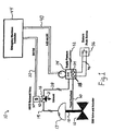
- FIG. 1 illustrates an example of an emergency shutdown test system 10 for testing an emergency shutdown (ESD) valve 12.
- ESD emergency shutdown
- the emergency shutdown valve 12 may be located, for example, in a process control system including a pipeline supplying fluid at the inlet to the emergency shutdown valve 12 and an outlet pipeline leading fluid from the outlet of the emergency shutdown valve 12.
- the emergency shutdown valve 12 is normally in one of two positions, either a wide open state permitting fluid to flow freely between the inlet pipeline and the outlet pipeline, or the emergency shutdown valve 12 is in a fully closed position preventing fluid flow between the inlet pipeline and the outlet pipeline.
- the emergency shutdown valve 12 may be periodically tested by partially opening or closing it, which is referred to as partially stroking the valve.
- the emergency shutdown test system 10 may include a Digital Valve Controller (DVC) 14 which may initiate a test of the operation of the emergency shutdown valve 12.
- DVC Digital Valve Controller
- the stem valve 18 is partially moved, and then returned to its normal state.
- a plurality of sensors 15 are placed on pressure lines and moveable components such that a plurality of parameters can be monitored.
- the emergency shutdown test may include a plurality of scripts or routines for the DVC 14.
- a few examples of executable scripts for gathering diagnostic data using sensors are: (1) length of the test stroke (i.e. valve stem travel), (2) rate of travel of the valve stem, (3) data acquired from the sensors during the emergency shutdown test, (4) sampling rate, (5) how long to dwell at the test target position, and (6) actuator pressure and time.
- the DVC 14 may also be configured to record the valve 12 behavior during emergency shutdown test conditions. These online valve diagnostics can be configured to start recording automatically when the emergency shutdown valve plug moves. The online valve diagnostics can be marked as an online diagnostic in a data record stored in the DVC 14, and can record any occurrence in which the valve plug moved away from its normal resting position, whether due to a request from the DVC 14 or unexpectedly. The DVC 14 may also be configured so that online diagnostic data collection is triggered when the loop current on the line 40 falls below a.predetermined level.
- predetermined limits include: minimum pressure, maximum pressure, sample rate, travel time, and travel deviation.
- the emergency shutdown test system 10 may include a solenoid valve 16 to supply pressure to move the emergency shutdown valve 12 to both an emergency position in the event an actual emergency exists, and to a partial stroke position (a predetermined position) during an emergency shutdown test.
- a valve actuator 17 may include a pneumatic input coupled to a pneumatic line 19 to move the emergency shutdown valve's plug (the valve's plug is not shown, but is connected to the valve's val ve stem 18) in response to a change in the pneumatic pressure in the pneumatic line 19.
- the solenoid valve 16 may include a solenoid control 20 which may receive dc power and electrical control signals on a two wire line 22.
- the solenoid control 20 may receive 24 volts of direct current over the line 22.
- the solenoid control 20 may provide an output on an output line 42 that is connected to the solenoid valve 16 to control the pressure at the output of the solenoid valve 16.
- the solenoid valve 16 and the solenoid control 20 may be used to provide redundancy for the emergency shutdown test system 10. The redundancy is achieved by allowing the solenoid valve 16 to open and exhaust the air pressure in the line 19 out an exhaust line 21, thus causing a spring on the actuator 17 to move the valve stem 18. In other words, an alternate route in the form of the exhaust line 21 is provided for reducing the air pressure in the line 19. Sensor data from the line 19 is compared to the valve stem travel data to determine if a valve stuck alarm should be activated.
- the DVC 14 may be operatively connected to the emergency shutdown valve 12 and may include a pneumatic output line 28 coupled to the solenoid valve 16.
- the DVC 14 may be powered by a pair of electrical lines 40 and communicate over a HART network (a communication protocol well known to those skilled in the art), or any other acceptable protocol.
- the pair of electrical lines 40 connects the DVC 14 to an emergency shutdown controller 44.
- a target plug position may be sent to the DVC 14 via a current signal on the pair of electrical lines 40, a digital setpoint from a control device using the HART protocol, or any other preconfigured default setpoint.
- the target plug position may be estimated by measuring the output pressure on line 28 which should be directly proportional to the position of the emergency shutdown valve's valve stem.
- the DVC 14 may cause air pressure to move the valve actuator 17 and use a position sensor 15 to measure the actual valve plug position of the emergency shutdown valve 12.
- the DVC 14 may continuously adjust the actuator output air pressure on line 28 to move the position of the valve plug to the desired target position after the DVC 14 receives a change in loop current, or a digital command via the communications protocol.
- the DVC 14 may include sensor inputs and auxiliary inputs.
- Auxiliary inputs can be connected to an external remote activation apparatus, such as, for example, a push button 36, via lines 46.
- a voltage may be present at a first auxiliary input
- the push button 36 may electrically connect the first auxiliary input to a second auxiliary input.
- the remote switch 36 may be an inexpensive electrical switch for initiating a partial stroke test of the emergency shutdown valve 12.
- the push button 36 may be located remote from the DVC 14 in any remote location that provides convenient access for a safety officer. An employee can press the remote switch 36 and witness the valve stroke and return to the normal state.
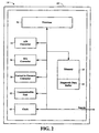
- the DVC 14 is a processor based emergency shutdown valve controller.
- the embodiment of Figure 2 includes some of the same structures and components as previously shown in Figure 1. For clarity, the structures and components remaining the same are shown with like reference numbers as those in Figure 1.
- the DVC 14 includes a processor 50, sensors 15, a memory 52, an analog-to-digital (A/D) converter 54, a digital to analog (D/A) converter 56, and a current to pressure converter 58.
- the memory 52 is utilized to store instructions or scripts and diagnostic data.
- the A/D converter 54 converts analog sensor inputs into digital signals for the processor 50 to process or store. Examples of sensor inputs acquired and stored by the DVC 14 include: valve stem travel (or valve plug travel), output line pressure, loop current, etc.
- the processor 50 monitors the auxiliary inputs such as the input for the electrical switch 36.
- the D/A converter 56 may convert a plurality of digital outputs from the processor 50 into analog signals such that the current to pressure converter 58 can provide a pressure based on digital data to drive the emergency shutdown valve actuator 17.
- the DVC 14 may be enclosed within a housing, such as an explosion proof housing 60 of Figure 2.
- the housing 60 may be used to prevent sparks from reaching explosive gasses in a plant, and thus reduce the likelihood that the emergency shutdown system 10 will cause an explosion. Locating the electrical switch 36 outside the housing 60 allows activation of an emergency shutdown test on an emergency shutdown device without setup or disassembly of the housing 60. In hazardous environments, the electrical switch 36 may be explosion proof, so that it does not create a spark when activated by a user.
- the solenoid valve 16 is maintained in a stand-by position to provide fluid flow between the pneumatic lines 19 and 28.
- the DVC 14 may receive a pressure supply from a supply line 32 and gather data from a valve stem sensor 15 to determine a valve stem position through the travel feedback linkage 30. The valve stem position is indicative of the valve plug position because they are connected. Furthermore, the DVC 14 may compare a predetermined valve plug setpoint that is stored in the memory 52 of the DVC 14, to the actual valve stem position, to verify the desired emergency shutdown valve plug position during normal operation. For example, low pressure on the line 19 would let the valve plug partially close, possibly creating problems in the process.
- a user may activate the electrical switch 36 to generate a signal, which is detected at the auxiliary input 34, wherein the DVC 14 controls the pressure supplied by the pneumatic line 28 and conveyed to the valve actuator 17, and the valve stem is moved from the normal 100 percent open (or closed) position (i.e. the normal state) to a partially closed (or partially opened) test position and then back again to the normal state.
- Emergency shutdown test systems utilizing auxiliary switches that are operably connected to DVCs are much less expensive, more convenient and quicker. If there is a valve that looks suspicious or that was recently rebuilt, a simple switch activation can reveal the operability of the valve.
- Emergency shutdown test systems utilizing auxiliary switches also have the ability to perform customized tests for each emergency shutdown valve or group of valves. This customization may be accomplished by one or more configurable scripts (i.e. computer programs or routines) stored in the memory 52 and retrievable by the processor 50.
- Additional tests may be conducted based on the diagnostic data collected.
- the sensor or diagnostic data collected during the emergency shutdown test may be retrieved using a handheld computing device through a communication unit 62 in the DVC 14, or the data may be sent back to the main control room.
- systems such as the emergency shutdown system 10 provide the capability of scheduling predictive maintenance based on the results of the partial stroke test.
- Figure 3 illustrates some of the steps for performing a remotely activated partial stroke ESD test.
- the process begins at a block 66 and proceeds to a block 68 where one or more predetermined limits are stored in a memory.
- a processor may continuously monitor an auxiliary input, as shown at a block 70, and sense if a signal from a remote switch has been received on the auxiliary input, as shown at a block 72.
- the processor may continue monitoring the auxiliary input at all times, even during the performance of an emergency shutdown test.
- the processor may retrieve a configurable script or routine unique to the emergency shutdown valve, for access by the processor.
- the processor may read and execute the script, as shown at a block 76.
- the scripts may be identified as an emergency shutdown partial stroke script by using a data byte encoded in a script record. Execution of the script by the processor may include activating the emergency shutdown valve actuator to move the valve stem and connected valve plug, by a predetermined amount (travel to target) and for a predetermined duration (time at target), at a predetermined velocity (time to target), as defined by the script.
- a clock 65 is operably connected to the processor 50 and provides a reference for all activities.
- the processor may monitor the sensor inputs, such as line pressures, solenoid position, and control data, as shown at a block 82.
- the processor may compare the data received at the monitored sensor inputs to predetermined limits, as shown at a block 84. As illustrated at a block 84, if the received data is outside of the predetermined limits, an alarm is set. Furthermore, some alarms may cause the processor to abort the emergency shutdown test and terminate processing of the script. Conditions for termination and corresponding alarm initiation may be user configured and utilize multiple alarms, for example, minimum output pressure (pressure supplied to the valve) and travel deviation.
- a Valve Stuck alarm may be generated as a result of data provided by sensors that indicates that the valve is not responding appropriately to a command. The conditions for alarms are described in greater detail immediately below.
- a first example of a possible alarm is shown at a block 86, which includes a Minimum Partial Stroke Pressure alarm.
- a partial stroke test could be aborted if the output pressure on line 28 falls below a predetermined level for a predetermined amount of time.
- the output pressure on line 28 is monitored by sensor 15 to detect a pressure drop below, a predetermined level.
- Another possible alarm shown in the block 86 includes, for example, a Travel Deviation alarm, wherein the actual travel of the emergency shutdown valve's valve stem is measured by travel sensor 15 and compared to the expected travel.
- the DVC's processor 50 controls the output pressure on the line 28 to determine if the two values (measured travel (position) and expected travel (pressure)) match.
- the match between the measured travel and expected travel need not be a perfect match, but may be a proportional match.
- Yet another alarm could include a Valve Stuck alarm which is set when the travel distance measured by the valve stem sensor deviates from the expected travel in excess of a predetermined distance as compared to the control pressure on the actuator 17.
- the DVC's processor 50 When conducting a partial stroke, the DVC's processor 50 causes the actuator 17 to move the valve stem of the emergency shutdown valve 12 through a pre-configured stroke profile, and back to the emergency shutdown valve's original position. During this procedure, the DVC 14 may collect and record sensor data and perform diagnostics, as shown at a block 82 of Figure 3.
- the partial stroke procedure is useful in locating faulty valves and increasing the reliability of an ESD system.
- the DVC's processor 50 generates a ramp signal which is mathematically added to the valve setpoint dictated by a control signal on the line 40, to cause movement of the valve plug to a target, and back again to the valve's normal position.
- the partial stroke procedure allows changes in the control signal to control the emergency shutdown valve 12 while the emergency shutdown test is in progress as well as allowing the emergency shutdown valve 12 to be stroked from its normal position, to any other position, and back to the normal position for purposes of stroke testing.
- the DVC's processor 50 is used to control the valve plugs movement by generating a ramp number and adding that ramp number to a second value that a user sends to the DVC 14 indicative of a position where the user wants the valve plug to be, the sum of which equals a target of the plug position that the controller attempts to maintain.
- This technique of moving the valve plug allows the user to specify the ramp rate and target for each step in the process of testing the valve 12, plus the sensor data to be collected (i.e. pressure, travel, requested target control signals, voltages, current to pressure drive current, timing, etc.) to be collected and the sampling rate for each sensor.
- a script for an emergency shutdown test may be configured so that an active setpoint (whether from the loop current or a HART signal) continues to be active, and the DVC's processor 50 generates a ramp signal that it is summed with the active setpoint, to produce a resulting travel to a target position.
- This technique allows the loop current to override the script-generated movements in case of an actual emergency shutdown during testing.
- An abort command i.e., a special message via HART or a second binary signal received by the auxiliary input at any time during the test may abort the test and immediately withdraw any setpoint bias generated by the script for test purposes.
- a user may initiate an emergency shutdown test by activating an external push button which provides a binary signal (on or off).
- the processor 50 may check at the contacts for a binary signal having a predetermined length of time before initiating the emergency shutdown test. For example, closing the auxiliary contacts for more than three seconds, but less than five seconds, could activate the emergency shutdown test.
- a routine stored in the memory 52 could cause the emergency shutdown test to be performed when the binary signal is received at the input for a time duration greater than a first threshold and less than a second threshold.
- the DVC may be configured so that opening the contacts after they have been closed for more than a predetermined time, such as five seconds, however, has no effect on the system 10.
- the DVC may be configured to prevent a test from activating if, for example: (1) commanded valve diagnostics are active, (2) no valid diagnostic script has been stored in the memory of the digital valve controller, (3) a script file is open for writing, or (4) there is a firmware download in progress. It will be appreciated by those skilled in the art that the DVC 14 may be configured so that any number of additional events may also prevent a test from being conducted.
- the emergency shutdown test system 10 can be configured so that a script cannot be written to a DVC while another script is executing.
- the emergency shutdown test system 10 could be configured to prevent an emergency shutdown partial stroke script from being initiated by a user activating the push button, unless the DVC is set to accept an auxiliary input, and an emergency shutdown partial stroke script is stored in the memory 52.
- the emergency shutdown test system 10 may be configured so that a signal sent using a control language will activate an ESD test script only if the script is an emergency shutdown partial stroke format.
- the emergency shutdown partial stroke test may function in a mode that is independent of a HART signal, so that the valve's last position is maintained independent of the signal.
- a HART command to execute a diagnostic may be rejected by the DVC's processor 50 wi th a "busy" signal, and an auxiliary current-to-pressure signal may result in aborting the emergency shutdown test (or prevent the emergency shutdown test from starting).
- An emergency shutdown test can be manually aborted by a signal at the auxiliary input for a predetermined amount of time, for example, activating the switch for one second.
- the occurrence of several events such as when the output pressure on the line 28 falls below the configured minimum partial stroke pressure for a predetermined amount of time may automatically abort an emergency shutdown test, depending on the configuration of the DVC.
- Other events that may cause the test to automatically abort include when the travel deviation alarm becomes set or if an emergency shutdown instrument is taken out of service via a command signal sent using the HART protocol.
- a stop diagnostics command from a dominant HART master would cause the emergency shutdown test to abort.
- the valve's target (movem ent to the desired position) is dictated by summing a present Implied Valve Position (IVP) with a ramped bias, wherein the ramped bias may be initialized to zero at the time the stroke is initiated.
- IVP Implied Valve Position
- the ESD control signal may continue to control a base IVP being used in the servo setpoint calculation, thus allowing the ESD control signal to effectively override a stroke diagnostic in emergency conditions.
- the setpoint bias produced by the test control may be forced to zero if the ESD control signal is less than a predetermined limit. Forcing the setpoint bias to zero may prevent an errant script from affecting an emergency shutdown.
- the DVC's processor 50 may disregard the ramp rate used in the test and use only the value sent via the ESD control signal.
- the emergency shutdown test system 10 may include cutoffs that are modified so that a high loop current cutoff can be a pressure controlled cutoff, but the low loop current cutoff will be overridden by any configured rate limits, but finally reduce the current-to-pressure drive to zero.
- the DVC 14 monitors a plurality of inputs, such as, for example, output pressure on the line 28, valve plug position, minimum partial stroke pressure on the line 19, and maximum travel deviation, from sensors 15 that are operably connected to the DVC14 for detecting a malfunctioning valve during an emergency shutdown test.
- a stuck valve plug may be detected when the valve plug fails to move as commanded, wherein the DVC 14 sets an alarm and alerts the user of the stuck valve plug.
- the DVC 14 could use an existing deviation alert which can be configured for a deviation amount (travel distance) and time, in conjunction with the existing Alert Event Record.
- Any computer system such as a handheld computer can be used to access the Alert Event Record by connecting the computer system to the communication unit of the DVC 14.
- Deviation Alert is activated during the test, the test could be terminated and a "Valve Stuck" marker (status bit) placed in the data file. Additionally, the Valve Stuck marker may be set and a record written to the Alert Event Record indicating a deviation alert.
- the test may be aborted, a Valve Stuck marker placed in a diagnostic data file, and the Valve Stuck alarm bit may be set.
- the alarm bit could remain set until the DVC's power is cycled, the next partial stroke is activated, or the data (the Valve Stuck marker) is read by a user. Diagnostic data may be collected in a diagnostic data buffer 64, as shown in Figure 2.
- the emergency shutdown test system 10 may further be configured to incorporate a continual pneumatic self-test.
- the pneumatic self test may continuously check the components of the DVC 14 by keeping the DVC 14 in a pressure control mode.
- the continuous pneumatic self test function may constantly analyze one or more pneumatic stages comparing sensor data to control commands, such as current-to-pressure data, to assure that the DVC 14 will be able to accurately control the emergency shutdown valve 12 when necessary.
- the emergency shutdown test system 10 may include a test for a pressure deviation alarm in the diagnostics.
- the pressure deviation alarm is set when a pressure controlled cutoff is active, and has passed through its "saturat ion" phase.
- the saturation phase is the phase when the DVC 14 causes the maximum amount of pressure to be applied to the actuator 17 and maintains that pressure for a predetermined amount of time to allow the pressure to stabilize, before reducing the pressure to a 'normal' target pressure, which is less than saturation, but sufficient to maintain the valve plug in the normal position.
- This pressure is the "target" pressure used in the pneumatic self test, and the ability to maintain the actual pressure at this target value determines the success of the pneumatic self test.
- the DVC's memory 52 may store a predetermined limit and determine the difference between the actual and expected pressures and set a pressure deviation alert if a condition occurs.
- a time of occurrence i.e. the actual time and date
- T he clock 65 may also record the pressure deviation alert time, which is the maximum amount of time (usually in seconds) the actual output pressure is allowed to differ from the expected pressure by a value that is greater than the pressure deviation alert trip point.
- the DVC's processor 50 may set the pressure deviation alarm status bit when the pressure on the output line 28 deviates from the expected pressure by an amount exceeding the pressure deviation alert trip point, for a predetermined amount of time.
- Logic for the pressure deviation alarm may be patterned after the travel deviation alarm. However, the count down for release of the pressure deviation alarm for the predetermined amount of time may be done at half the rate of the count up for setting the pressure deviation alarm. Reducing the count down for release of the pressure deviation alarm causes the alert to persist for approximately ten seconds after the deviation clears, but the pressure deviation alarm may be designed so that symmetric oscillations of the pressure signal, such as would occur due to loss of feedback quality, will cause the alert to be set.
Landscapes
- Engineering & Computer Science (AREA)
- Physics & Mathematics (AREA)
- General Physics & Mathematics (AREA)
- Automation & Control Theory (AREA)
- General Engineering & Computer Science (AREA)
- Manufacturing & Machinery (AREA)
- Quality & Reliability (AREA)
- Testing And Monitoring For Control Systems (AREA)
- Safety Devices In Control Systems (AREA)
- Testing Of Devices, Machine Parts, Or Other Structures Thereof (AREA)
Description
Claims (19)
- An emergency shutdown test system (10) adapted to communicate with a portable handheld computing device, the test system comprising:an emergency shutdown device controller (14) having:a processor(50);a memory (52) coupled to the processor (50), wherein an emergency shutdown test procedure is stored in the memory (52);an auxiliary input (34) coupled to the processor (50) and adapted to receive a binary signal from a switch (36), wherein the switch (36) is accessible to a user and coupled directly to the auxiliary input (34);a first routine (66-76) stored in the memory (52) and adapted to be executed on the processor (50) to cause the emergency shutdown test procedure to be performed in response to the receipt of the binary signal received from the switch (36) at the auxiliary input (34);a second routine (82) stored in the memory (52) and adapted to be executed on the processor (50) to acquire data from a sensor (15) and to cause the data to be stored in the memory (52, 64), during the emergency shutdown test; anda third routine (84-86) stored in the memory (52) and adapted to be executed on the processor (50) to compare the data acquired from the sensor (15) to the at least one predetermined limit and create an alarm if the difference between the data and the at least one predetermined limit is greater than a predetermined threshold.
- The emergency shutdown test system (10) of claim 1, further including a communication unit (62), wherein the communication unit (62) is coupled to the processor (50) and communicates with the portable handheld computing device.
- The emergency shutdown test system (10) of claim 1, wherein the first routine (66-76) is further adapted to prevent the activation of the emergency shutdown test unless an auxiliary-input-type is activated.
- The emergency shutdown test system (10) of claim 1, wherein the first and second routines (66-82) comprise valve specific, configurable scripts.
- The emergency shutdown test system (10) of claim 1, further including an emergency shutdown valve (12).
- The emergency shutdown test system (10) of claim 5, wherein the second routine (82) is further adapted to cause a valve plug setpoint to be compared to an actual valve stem position of the emergency shutdown valve (12).
- The emergency shutdown test system (10) of claim 5, wherein the emergency shutdown test procedure includes a partial stroke test for the emergency shutdown valve (12).
- The emergency shutdown test system (10) of claim 5, wherein the second routine (82) stored in the memory (52) is further adapted to automatically cause the processor (50) to acquire data from a sensor (15) when a valve plug of the valve (12) moves.
- The emergency shutdown test system (10) of claim 5, wherein the emergency shutdown device controller (14) further includes an analog-to-digital ("A/D") converter (54) to convert an analog input from a sensor (15) to digital data for utilization by the processor (50).
- The emergency shutdown test system (10) of claim 9, wherein the analog input converted by the A/D converter (54) includes an analog input selected from the group of analog inputs consisting of: valve stem travel, line pressure, loop current, and binary signal generation.
- The emergency shutdown test system (10) of claim 1, wherein the second routine (82) is further adapted to cause an input (34) that is coupled to the processor to be monitored, during the emergency shutdown test procedure, for one of several conditions that would cause the emergency shutdown test to be aborted.
- The emergency shutdown test system (10) of claim 11, wherein the conditions are selected from a group of conditions consisting of: minimum partial stroke pressure, travel deviation, and valve stuck.
- A method of conducting an emergency shutdown test on an emergency shutdown valve, comprising:storing an emergency shutdown test script in a memory of a controller;monitoring an input coupled to the controller for the receipt of a binary signal received from a test initiation switch that is accessible to a user;monitoring the input for the receipt of a digital signal received from the portable handheld computing device;activating the test script in response to at least one of the binary signal received from the test initiation switch, or the digital signal that is received from the portable handheld computing device;storing at least one predetermined limit in the memory of the controller;activating the test initiation switch to perform the emergency shutdown test, wherein a processor is responsive to the switch activation;acquiring sensor data from a sensor and storing the sensor data in the memory; andcomparing the sensor data to the at least one predetermined limit and creating an alarm if the difference between the sensor data and the at least one predetermined limit is greater than a predetermined threshold.
- The method of claim 13, further comprising aborting the emergency shutdown test if an alarm is created.
- The method of claim 13, further comprising transferring the sensor data to the portable handheld computing device.
- The method of claim 13, wherein the step of comparing the sensor data includes comparing a valve plug setpoint to an actual valve stem position.
- The method of claim 13, wherein the step of storing the emergency shutdown test script includes storing a partial stroke test for the emergency shutdown valve.
- The method of claim 13, further comprising converting an analog input from a sensor to digital data for utilization by a processor of the controller.
- The method of claim 13, further comprising causing a plurality of inputs that are coupled to a processor of the controller to be monitored for one of several conditions that would cause the emergency shutdown test to be aborted.
Applications Claiming Priority (3)
| Application Number | Priority Date | Filing Date | Title |
|---|---|---|---|
| US28185201P | 2001-04-05 | 2001-04-05 | |
| US281852P | 2001-04-05 | ||
| PCT/US2002/010790 WO2002082193A2 (en) | 2001-04-05 | 2002-04-05 | System to manually initiate an emergency shutdown test and collect diagnostic data in a process control environment |
Publications (2)
| Publication Number | Publication Date |
|---|---|
| EP1417552A2 EP1417552A2 (en) | 2004-05-12 |
| EP1417552B1 true EP1417552B1 (en) | 2005-12-14 |
Family
ID=23079054
Family Applications (1)
| Application Number | Title | Priority Date | Filing Date |
|---|---|---|---|
| EP02723781A Expired - Lifetime EP1417552B1 (en) | 2001-04-05 | 2002-04-05 | System to manually initiate an emergency shutdown test and collect diagnostic data in a process control environment |
Country Status (9)
| Country | Link |
|---|---|
| US (2) | US6862547B2 (en) |
| EP (1) | EP1417552B1 (en) |
| JP (2) | JP4121378B2 (en) |
| CN (2) | CN1264076C (en) |
| AU (1) | AU2002254547A1 (en) |
| BR (2) | BR0208201A (en) |
| CA (1) | CA2443376C (en) |
| DE (1) | DE60208046T2 (en) |
| WO (2) | WO2002082199A1 (en) |
Cited By (2)
| Publication number | Priority date | Publication date | Assignee | Title |
|---|---|---|---|---|
| US20100089473A1 (en) * | 2007-05-02 | 2010-04-15 | Nicolas Grein | Method for checking the operability of an actuator |
| CN102865451A (en) * | 2011-07-04 | 2013-01-09 | 美卓造纸机械公司 | Safety component |
Families Citing this family (98)
| Publication number | Priority date | Publication date | Assignee | Title |
|---|---|---|---|---|
| US7254518B2 (en) | 1996-03-28 | 2007-08-07 | Rosemount Inc. | Pressure transmitter with diagnostics |
| US8290721B2 (en) | 1996-03-28 | 2012-10-16 | Rosemount Inc. | Flow measurement diagnostics |
| US7630861B2 (en) | 1996-03-28 | 2009-12-08 | Rosemount Inc. | Dedicated process diagnostic device |
| US6862547B2 (en) * | 2001-04-05 | 2005-03-01 | Saudi Arabian Oil Company | Control device test system with a remote switch activation |
| US7621293B2 (en) | 2001-04-05 | 2009-11-24 | Fisher Controls International Llc | Versatile emergency shutdown device controller implementing a pneumatic test for a system instrument device |
| US6898542B2 (en) * | 2003-04-01 | 2005-05-24 | Fisher-Rosemount Systems, Inc. | On-line device testing block integrated into a process control/safety system |
| US7130703B2 (en) * | 2003-04-08 | 2006-10-31 | Fisher-Rosemount Systems, Inc. | Voter logic block including operational and maintenance overrides in a process control system |
| DE10320031A1 (en) * | 2003-05-06 | 2004-12-16 | Samson Ag | Safety actuator testing method for checking the operation of actuators and control elements in a safety circuit of a process control system, whereby the control elements are partially moved and their movement detected with sensors |
| US7280048B2 (en) * | 2003-08-07 | 2007-10-09 | Rosemount Inc. | Process control loop current verification |
| US8180466B2 (en) | 2003-11-21 | 2012-05-15 | Rosemount Inc. | Process device with supervisory overlayer |
| US20050109395A1 (en) * | 2003-11-25 | 2005-05-26 | Seberger Steven G. | Shut down apparatus and method for use with electro-pneumatic controllers |
| US7523667B2 (en) | 2003-12-23 | 2009-04-28 | Rosemount Inc. | Diagnostics of impulse piping in an industrial process |
| CN100511058C (en) * | 2004-02-05 | 2009-07-08 | 罗斯蒙德公司 | Emergency shut-off valve diagnostics using pressure transmitters |
| US8234414B2 (en) * | 2004-03-31 | 2012-07-31 | Qurio Holdings, Inc. | Proxy caching in a photosharing peer-to-peer network to improve guest image viewing performance |
| US7464721B2 (en) * | 2004-06-14 | 2008-12-16 | Rosemount Inc. | Process equipment validation |
| CN100535816C (en) * | 2005-02-28 | 2009-09-02 | 罗斯蒙德公司 | Process connection for process diagnostics |
| US7504961B2 (en) * | 2005-03-31 | 2009-03-17 | Saudi Arabian Oil Company | Emergency isolation valve controller with integral fault indicator |
| US8072343B2 (en) * | 2005-03-31 | 2011-12-06 | Saudi Arabian Oil Company | Local emergency isolation valve controller with diagnostic testing and trouble indicator |
| DE102005024686B4 (en) * | 2005-05-30 | 2015-10-22 | Samson Ag | positioner |
| US7636613B2 (en) * | 2005-07-01 | 2009-12-22 | Curtiss-Wright Flow Control Corporation | Actuator controller for monitoring health and status of the actuator and/or other equipment |
| US7556238B2 (en) * | 2005-07-20 | 2009-07-07 | Fisher Controls International Llc | Emergency shutdown system |
| US7852610B2 (en) * | 2006-01-24 | 2010-12-14 | Fisher Controls International Llc | Flameproof apparatus using non-grounded energy-limiting barrier |
| US7661439B2 (en) | 2006-02-07 | 2010-02-16 | Dresser, Inc. | Safety override circuit for pneumatic positioner and method of use thereof |
| US7283894B2 (en) * | 2006-02-10 | 2007-10-16 | Dresser, Inc. | System and method for fluid regulation |
| EA008973B1 (en) * | 2006-04-21 | 2007-10-26 | Закрытое Акционерное Общество "Белтехэкспорт" | Test equipment |
| US7953501B2 (en) * | 2006-09-25 | 2011-05-31 | Fisher-Rosemount Systems, Inc. | Industrial process control loop monitor |
| US7905251B2 (en) * | 2006-12-29 | 2011-03-15 | Saudi Arabian Oil Company | Method for wellhead high integrity protection system |
| US20110133942A1 (en) * | 2006-12-29 | 2011-06-09 | Flanders Patrick S | Apparatus and method for clustered wellhead high integrity protection system |
| US8725434B2 (en) * | 2006-12-29 | 2014-05-13 | Saudi Arabian Oil Company | Wellhead hips with automatic testing and self-diagnostics |
| US7539560B2 (en) * | 2007-01-05 | 2009-05-26 | Dresser, Inc. | Control valve and positioner diagnostics |
| US8573241B2 (en) * | 2007-03-30 | 2013-11-05 | Dresser, Inc. | Systems and processes for field-initiated fluid regulation testing |
| DE102007016817A1 (en) * | 2007-04-05 | 2008-10-09 | Siemens Ag | Method for checking the functionality of a positioning device |
| DE102007029148B4 (en) * | 2007-06-25 | 2021-09-30 | Abb Ag | Procedure for testing the functionality of fittings |
| JP4941748B2 (en) * | 2007-07-19 | 2012-05-30 | 横河電機株式会社 | Safety control system |
| DE102007034060B4 (en) * | 2007-07-20 | 2012-11-08 | Siemens Ag | Actuator for an on / off valve |
| US8898036B2 (en) | 2007-08-06 | 2014-11-25 | Rosemount Inc. | Process variable transmitter with acceleration sensor |
| US8201624B2 (en) * | 2007-10-23 | 2012-06-19 | Saudi Arabian Oil Company | Clustered wellhead trunkline protection and testing system with ESP speed controller and emergency isolation valve |
| US7869889B2 (en) * | 2008-07-02 | 2011-01-11 | Saudi Arabian Oil Company | Distributed and adaptive smart logic with multi-communication apparatus for reliable safety system shutdown |
| DE102008033047A1 (en) * | 2008-07-14 | 2010-02-25 | Abb Technology Ag | Signaling the active safety position for electro-pneumatic positioners |
| CN103411024B (en) * | 2008-07-25 | 2016-01-27 | 诺格伦有限公司 | Automated valve testing apparatus |
| JP5548196B2 (en) * | 2008-07-25 | 2014-07-16 | ノアグレン リミテッド | Automated valve test equipment |
| DE102008038723B3 (en) * | 2008-08-12 | 2010-04-15 | Abb Technology Ag | Method and device for controlling an electropneumatic valve of a pressure-medium-actuated positioner |
| US8056390B2 (en) * | 2008-09-22 | 2011-11-15 | Honeywell International Inc. | Partial stroke testing with pulsed control loop |
| US8413499B2 (en) | 2008-09-22 | 2013-04-09 | Honeywell International Inc. | Partial stroke testing |
| US8237389B2 (en) * | 2008-11-12 | 2012-08-07 | Irobot Corporation | Multi mode safety control module |
| US9874870B2 (en) * | 2009-08-26 | 2018-01-23 | Fisher-Rosemount Systems, Inc. | Methods and apparatus to manage testing of a process control system |
| BR112012003290A2 (en) * | 2009-09-03 | 2016-03-01 | Fisher Controls Int | test control panel device, test system, and, computer program product |
| US8996328B2 (en) * | 2009-12-29 | 2015-03-31 | Fisher Controls International Llc | Methods, apparatus and articles of manufacture to test safety instrumented system solenoids |
| WO2011146385A1 (en) * | 2010-05-15 | 2011-11-24 | Procontroll Zone Systems, Llc | Zone shut-down control system |
| MX2013004432A (en) * | 2010-10-21 | 2013-06-03 | Saudi Arabian Oil Co | Clustered wellhead trunkline protection and testing system with esp speed controller and emergency isolation valve. |
| US20120167996A1 (en) * | 2011-01-05 | 2012-07-05 | Fisher Controls International Llc | Valve Controller Automatic Calibration Without User Interface |
| CN103493033B (en) * | 2011-01-19 | 2016-03-16 | 沙特阿拉伯石油公司 | High-integrity protective system and test thereof and method of operating |
| CA2826083A1 (en) * | 2011-02-03 | 2012-08-09 | Anderson Instrument Company Inc. | Sensor assembly for hygenic material processing systems |
| US8838413B2 (en) | 2011-05-12 | 2014-09-16 | Saudi Arabian Oil Company | Valve actuator fault analysis system |
| FR2978248B1 (en) * | 2011-07-20 | 2013-08-02 | Inf Cdc | DEVICE FOR VERIFYING THE CORRECT OPERATION OF THE CONTROL CHAIN OF A SYSTEM FOR CUTTING AND EMERGENCY STOPPING OF AN ELECTRICAL INSTALLATION |
| US9020768B2 (en) | 2011-08-16 | 2015-04-28 | Rosemount Inc. | Two-wire process control loop current diagnostics |
| US9285803B2 (en) * | 2012-02-29 | 2016-03-15 | Fisher Controls International Llc | Scheduling function in a wireless control device |
| CN103308288A (en) * | 2012-04-24 | 2013-09-18 | 浙江三方控制阀股份有限公司 | Diagnosis device of valve and diagnosis method applying same |
| US8744604B2 (en) * | 2012-05-09 | 2014-06-03 | Fisher Controls International Llc | Method and apparatus for configuring a blackout period for scheduled diagnostic checks of a field device in a process plant |
| JP6006635B2 (en) | 2012-12-26 | 2016-10-12 | アズビル株式会社 | Safety instrumentation system and PST activation method |
| JP6071534B2 (en) | 2012-12-26 | 2017-02-01 | アズビル株式会社 | Safety instrumentation system and PST activation method |
| US9404515B2 (en) * | 2013-07-09 | 2016-08-02 | Dresser, Inc. | Valve positioner having bypass component and control value comprised thereof |
| EP3204832B1 (en) * | 2014-10-06 | 2022-11-30 | Fisher Controls International Llc | Cut-off transition for control valve positioners |
| US11137000B2 (en) | 2014-10-10 | 2021-10-05 | MEA Inc. | Self-contained energy efficient hydraulic actuator system |
| DE102014019419A1 (en) | 2014-12-22 | 2016-06-23 | GM Global Technology Operations LLC (n. d. Ges. d. Staates Delaware) | Method and diagnostic device for checking high-pressure tank valves, high-pressure tank system and motor vehicle with a high-pressure tank system |
| US9611873B2 (en) * | 2015-03-19 | 2017-04-04 | Fisher Controls International Llc | Pressure control for partial stroke tests |
| US20160363919A1 (en) * | 2015-06-09 | 2016-12-15 | Fisher Controls International Llc | Custom application environment in a process control device |
| US10238184B2 (en) | 2015-06-30 | 2019-03-26 | Control Dynamics Inc. | Locking mechanism with one and two-stage locking verification |
| US10568393B2 (en) * | 2015-06-30 | 2020-02-25 | Control Dynamics, Inc. | Locking mechanism with multiple stage locking verification |
| US10085520B2 (en) * | 2015-06-30 | 2018-10-02 | Control Dynamics Inc. | Control docking station for a one or two stage locking mechanism |
| US10367612B2 (en) | 2015-09-30 | 2019-07-30 | Rosemount Inc. | Process variable transmitter with self-learning loop diagnostics |
| US10480681B2 (en) * | 2015-12-23 | 2019-11-19 | Fisher Controls International Llc | Partial stroke tests for shutdown valves |
| JP6688665B2 (en) | 2016-04-11 | 2020-04-28 | 横河電機株式会社 | Equipment maintenance device, equipment maintenance method, equipment maintenance program and recording medium |
| AT518665B1 (en) * | 2016-05-06 | 2017-12-15 | Keba Ag | Control system for electrically controlled systems |
| US10060552B2 (en) * | 2016-05-18 | 2018-08-28 | Saudi Arabian Oil Company | Adaptive high integrity ESD system |
| US12346103B2 (en) * | 2016-07-07 | 2025-07-01 | Ats Corporation | System and method for diagnosing a manufacturing line using tagged data |
| US10240686B2 (en) * | 2016-08-18 | 2019-03-26 | Fisher Controls International Llc | Methods and apparatus for conducting in-service testing of pneumatic signal amplifiers |
| US10234840B2 (en) | 2016-09-08 | 2019-03-19 | Saudi Arabian Oil Company | Emergency shutdown system for dynamic and high integrity operations |
| CN107918680A (en) * | 2016-10-08 | 2018-04-17 | 深圳指瑞威科技有限公司 | A kind of ESD protection structure and its modeling method based on fingerprint sensor |
| US10234058B2 (en) | 2016-10-20 | 2019-03-19 | Fisher Controls International Llc | Methods and apparatus of assessing a test of a solenoid valve via a positioner |
| US10240687B2 (en) * | 2016-10-20 | 2019-03-26 | Fisher Controls International Llc | Methods and apparatus of testing a solenoid valve of an emergency valve via a positioner |
| US10114981B2 (en) * | 2016-12-31 | 2018-10-30 | Intel Corporation | Architecture for telemetry and adaptive lifetime control of integrated circuits |
| US10557564B2 (en) | 2017-01-07 | 2020-02-11 | Saudi Arabian Oil Company | Locally-actuated partial stroke testing system |
| RU2745235C1 (en) * | 2017-04-21 | 2021-03-22 | Компрессор Контролз Корпорейшен | System and method for control valve wear detection |
| GB2566109B (en) * | 2017-09-05 | 2020-04-15 | Bifold Fluidpower Ltd | Valve actuator |
| CN108386595B (en) * | 2018-02-13 | 2019-08-30 | 东莞三江港口储罐有限公司 | An emergency cut-off device for petrochemical storage industry |
| DE102018214295A1 (en) | 2018-08-23 | 2020-02-27 | Stabilus Gmbh | Measurement of operating parameters on actuators |
| US11042129B2 (en) | 2019-06-05 | 2021-06-22 | Control Dynamics, Inc. | Redundant wireless safety system for manufacturing environment |
| JP7417376B2 (en) * | 2019-07-31 | 2024-01-18 | アズビル株式会社 | Valve maintenance support device and support method |
| DE102019129368B4 (en) | 2019-10-30 | 2025-01-30 | Samson Aktiengesellschaft | Determining termination criteria for a partial stroke test on a fluid-driven safety valve and determining the functionality of a fluid-driven safety valve |
| US11101632B2 (en) * | 2019-11-12 | 2021-08-24 | Saudi Arabian Oil Company | High current detection and field loop isolation circuit |
| CN111367162A (en) * | 2020-04-29 | 2020-07-03 | 大连理工度达安全工程有限公司 | Dust explosion suppression controller |
| CN111537187B (en) * | 2020-04-29 | 2022-01-25 | 中国汽车工程研究院股份有限公司 | Force and flow field multi-technology linkage measurement control method and system |
| LU102418B1 (en) * | 2021-01-12 | 2022-07-12 | Phoenix Contact Gmbh & Co | Technique for validating a safety function of a controller |
| CN112904827B (en) * | 2021-01-18 | 2022-02-01 | 同济大学 | Unmanned virtual simulation test system for multiple ICUs |
| JP2022155008A (en) | 2021-03-30 | 2022-10-13 | 横河電機株式会社 | field equipment |
| US12398740B1 (en) * | 2024-02-27 | 2025-08-26 | Saudi Arabian Oil Company | Methods and systems of failure protection for automated valves |
| CN119126728B (en) * | 2024-11-12 | 2025-05-09 | 上海朋熙半导体有限公司 | Free shutdown control system, method and equipment for semiconductor production process |
Family Cites Families (23)
| Publication number | Priority date | Publication date | Assignee | Title |
|---|---|---|---|---|
| US3829842A (en) | 1973-02-22 | 1974-08-13 | Terry Controls Corp | Automatic self-testing programmable industrial controller |
| US4428223A (en) * | 1978-05-16 | 1984-01-31 | Furmanite International Limited | Apparatus for periodically testing the operation of safety valves |
| GB8321751D0 (en) * | 1983-08-12 | 1983-09-14 | Greenwood Moore Ltd | Valve testing |
| US5000040A (en) * | 1986-04-04 | 1991-03-19 | Movats Incorporated | Method and apparatus for remote monitoring of valves and valve operators |
| US5109692A (en) | 1988-08-25 | 1992-05-05 | Fisher Controls International Inc. | Diagnostic apparatus and method for fluid control valves |
| JP2876214B2 (en) * | 1988-12-16 | 1999-03-31 | 株式会社 金門製作所 | Flowmeter |
| US5363290A (en) * | 1990-07-18 | 1994-11-08 | The Toro Company | Irrigation controller |
| US5154314A (en) * | 1991-03-29 | 1992-10-13 | Roger Van Wormer | System for transport, delivery and dispensation of industrial liquid fluids |
| US5329956A (en) | 1993-05-28 | 1994-07-19 | Combustion Engineering, Inc. | Pneumatic operated valve stroke timing |
| US5549137A (en) * | 1993-08-25 | 1996-08-27 | Rosemount Inc. | Valve positioner with pressure feedback, dynamic correction and diagnostics |
| AU7634494A (en) * | 1993-09-15 | 1995-04-03 | Combustion Engineering Inc. | Diagnostic data acquisitioner for a valve |
| US5469737A (en) * | 1993-12-20 | 1995-11-28 | Westinghouse Electric Corporation | Method and apparatus for measuring the axial load and position of a valve stem |
| US5434774A (en) * | 1994-03-02 | 1995-07-18 | Fisher Controls International, Inc. | Interface apparatus for two-wire communication in process control loops |
| JP3341511B2 (en) | 1995-01-13 | 2002-11-05 | 富士電機株式会社 | Stem-free test equipment for main steam stop valve |
| US6017143A (en) | 1996-03-28 | 2000-01-25 | Rosemount Inc. | Device in a process system for detecting events |
| US5970430A (en) * | 1996-10-04 | 1999-10-19 | Fisher Controls International, Inc. | Local device and process diagnostics in a process control network having distributed control functions |
| DE19643297C1 (en) | 1996-10-21 | 1998-03-12 | Samson Ag | In-service monitoring method for servo equipment |
| US5870317A (en) * | 1997-05-21 | 1999-02-09 | Barnett; Ralph L. | Remote and proximal interlock testing mechanisms and testing systems |
| US6466893B1 (en) * | 1997-09-29 | 2002-10-15 | Fisher Controls International, Inc. | Statistical determination of estimates of process control loop parameters |
| FI116587B (en) * | 1997-10-17 | 2005-12-30 | Metso Automation Oy | Method and apparatus for determining the functionality of a safety device |
| US6186167B1 (en) * | 1999-03-04 | 2001-02-13 | Fisher Controls International Inc. | Emergency shutdown test system |
| MY123548A (en) * | 1999-11-08 | 2006-05-31 | Shell Int Research | Method and system for suppressing and controlling slug flow in a multi-phase fluid stream |
| US6862547B2 (en) * | 2001-04-05 | 2005-03-01 | Saudi Arabian Oil Company | Control device test system with a remote switch activation |
-
2002
- 2002-04-05 US US10/116,940 patent/US6862547B2/en not_active Expired - Lifetime
- 2002-04-05 DE DE60208046T patent/DE60208046T2/en not_active Expired - Lifetime
- 2002-04-05 EP EP02723781A patent/EP1417552B1/en not_active Expired - Lifetime
- 2002-04-05 BR BR0208201-2A patent/BR0208201A/en not_active Application Discontinuation
- 2002-04-05 BR BR0204829-9A patent/BR0204829A/en not_active Application Discontinuation
- 2002-04-05 WO PCT/US2002/010758 patent/WO2002082199A1/en not_active Ceased
- 2002-04-05 WO PCT/US2002/010790 patent/WO2002082193A2/en not_active Ceased
- 2002-04-05 CN CNB028020014A patent/CN1264076C/en not_active Expired - Fee Related
- 2002-04-05 CN CNB02809929XA patent/CN1288520C/en not_active Expired - Lifetime
- 2002-04-05 US US10/117,007 patent/US7079021B2/en not_active Expired - Lifetime
- 2002-04-05 CA CA002443376A patent/CA2443376C/en not_active Expired - Lifetime
- 2002-04-05 AU AU2002254547A patent/AU2002254547A1/en not_active Abandoned
- 2002-04-05 JP JP2002580096A patent/JP4121378B2/en not_active Expired - Fee Related
-
2007
- 2007-08-01 JP JP2007200692A patent/JP2008004113A/en active Pending
Cited By (3)
| Publication number | Priority date | Publication date | Assignee | Title |
|---|---|---|---|---|
| US20100089473A1 (en) * | 2007-05-02 | 2010-04-15 | Nicolas Grein | Method for checking the operability of an actuator |
| CN102865451A (en) * | 2011-07-04 | 2013-01-09 | 美卓造纸机械公司 | Safety component |
| CN102865451B (en) * | 2011-07-04 | 2016-03-09 | 维美德技术有限公司 | security component |
Also Published As
| Publication number | Publication date |
|---|---|
| JP2004533681A (en) | 2004-11-04 |
| BR0208201A (en) | 2004-03-02 |
| JP4121378B2 (en) | 2008-07-23 |
| AU2002254547A1 (en) | 2002-10-21 |
| CA2443376C (en) | 2007-05-29 |
| BR0204829A (en) | 2003-07-01 |
| CN1264076C (en) | 2006-07-12 |
| EP1417552A2 (en) | 2004-05-12 |
| DE60208046T2 (en) | 2006-08-03 |
| US6862547B2 (en) | 2005-03-01 |
| CA2443376A1 (en) | 2002-10-17 |
| US20030062494A1 (en) | 2003-04-03 |
| JP2008004113A (en) | 2008-01-10 |
| CN1288520C (en) | 2006-12-06 |
| WO2002082193A3 (en) | 2004-02-12 |
| US20020145515A1 (en) | 2002-10-10 |
| DE60208046D1 (en) | 2006-01-19 |
| US7079021B2 (en) | 2006-07-18 |
| WO2002082193A2 (en) | 2002-10-17 |
| CN1509428A (en) | 2004-06-30 |
| WO2002082199A1 (en) | 2002-10-17 |
| CN1463395A (en) | 2003-12-24 |
Similar Documents
| Publication | Publication Date | Title |
|---|---|---|
| EP1417552B1 (en) | System to manually initiate an emergency shutdown test and collect diagnostic data in a process control environment | |
| CN101360944B (en) | Universal Emergency Shutdown Device Controller | |
| US8072343B2 (en) | Local emergency isolation valve controller with diagnostic testing and trouble indicator | |
| US7516043B2 (en) | Triggered field device data collection in a process control system | |
| JP2001521213A (en) | Method and apparatus for verifying the performance of a safety device | |
| US5422808A (en) | Method and apparatus for fail-safe control of at least one electro-mechanical or electro-hydraulic component | |
| EP2676060B1 (en) | Method and apparatus for partial stroke testing of an emergency shutdown valve | |
| RU2577415C2 (en) | Automatic calibration of valve control device without user interface | |
| US20040030721A1 (en) | Device and method for data mirroring | |
| JPH04225118A (en) | Apparatus and method for analyzing system |
Legal Events
| Date | Code | Title | Description |
|---|---|---|---|
| PUAI | Public reference made under article 153(3) epc to a published international application that has entered the european phase |
Free format text: ORIGINAL CODE: 0009012 |
|
| 17P | Request for examination filed |
Effective date: 20031103 |
|
| AK | Designated contracting states |
Kind code of ref document: A2 Designated state(s): AT BE CH CY DE DK ES FI FR GB GR IE IT LI LU MC NL PT SE TR |
|
| AX | Request for extension of the european patent |
Extension state: AL LT LV MK RO SI |
|
| 17Q | First examination report despatched |
Effective date: 20040611 |
|
| GRAP | Despatch of communication of intention to grant a patent |
Free format text: ORIGINAL CODE: EPIDOSNIGR1 |
|
| RBV | Designated contracting states (corrected) |
Designated state(s): DE FI FR GB SE |
|
| GRAS | Grant fee paid |
Free format text: ORIGINAL CODE: EPIDOSNIGR3 |
|
| GRAA | (expected) grant |
Free format text: ORIGINAL CODE: 0009210 |
|
| AK | Designated contracting states |
Kind code of ref document: B1 Designated state(s): DE FI FR GB SE |
|
| REG | Reference to a national code |
Ref country code: GB Ref legal event code: FG4D |
|
| REG | Reference to a national code |
Ref country code: SE Ref legal event code: TRGR |
|
| REF | Corresponds to: |
Ref document number: 60208046 Country of ref document: DE Date of ref document: 20060119 Kind code of ref document: P |
|
| ET | Fr: translation filed | ||
| PLBE | No opposition filed within time limit |
Free format text: ORIGINAL CODE: 0009261 |
|
| STAA | Information on the status of an ep patent application or granted ep patent |
Free format text: STATUS: NO OPPOSITION FILED WITHIN TIME LIMIT |
|
| 26N | No opposition filed |
Effective date: 20060915 |
|
| PGFP | Annual fee paid to national office [announced via postgrant information from national office to epo] |
Ref country code: SE Payment date: 20120411 Year of fee payment: 11 |
|
| REG | Reference to a national code |
Ref country code: SE Ref legal event code: EUG |
|
| PG25 | Lapsed in a contracting state [announced via postgrant information from national office to epo] |
Ref country code: SE Free format text: LAPSE BECAUSE OF NON-PAYMENT OF DUE FEES Effective date: 20130406 |
|
| REG | Reference to a national code |
Ref country code: FR Ref legal event code: PLFP Year of fee payment: 15 |
|
| REG | Reference to a national code |
Ref country code: FR Ref legal event code: PLFP Year of fee payment: 16 |
|
| REG | Reference to a national code |
Ref country code: FR Ref legal event code: PLFP Year of fee payment: 17 |
|
| PGFP | Annual fee paid to national office [announced via postgrant information from national office to epo] |
Ref country code: DE Payment date: 20200319 Year of fee payment: 19 |
|
| PGFP | Annual fee paid to national office [announced via postgrant information from national office to epo] |
Ref country code: FR Payment date: 20210323 Year of fee payment: 20 Ref country code: FI Payment date: 20210325 Year of fee payment: 20 |
|
| PGFP | Annual fee paid to national office [announced via postgrant information from national office to epo] |
Ref country code: GB Payment date: 20210324 Year of fee payment: 20 |
|
| REG | Reference to a national code |
Ref country code: DE Ref legal event code: R119 Ref document number: 60208046 Country of ref document: DE |
|
| PG25 | Lapsed in a contracting state [announced via postgrant information from national office to epo] |
Ref country code: DE Free format text: LAPSE BECAUSE OF NON-PAYMENT OF DUE FEES Effective date: 20211103 |
|
| REG | Reference to a national code |
Ref country code: GB Ref legal event code: PE20 Expiry date: 20220404 |
|
| REG | Reference to a national code |
Ref country code: FI Ref legal event code: MAE |
|
| PG25 | Lapsed in a contracting state [announced via postgrant information from national office to epo] |
Ref country code: GB Free format text: LAPSE BECAUSE OF EXPIRATION OF PROTECTION Effective date: 20220404 |