WO2013191214A1 - Détecteur de courbe - Google Patents
Détecteur de courbe Download PDFInfo
- Publication number
- WO2013191214A1 WO2013191214A1 PCT/JP2013/066869 JP2013066869W WO2013191214A1 WO 2013191214 A1 WO2013191214 A1 WO 2013191214A1 JP 2013066869 W JP2013066869 W JP 2013066869W WO 2013191214 A1 WO2013191214 A1 WO 2013191214A1
- Authority
- WO
- WIPO (PCT)
- Prior art keywords
- bending
- unit
- light
- sensor
- holding
- Prior art date
Links
Images


Classifications
-
- G—PHYSICS
- G01—MEASURING; TESTING
- G01B—MEASURING LENGTH, THICKNESS OR SIMILAR LINEAR DIMENSIONS; MEASURING ANGLES; MEASURING AREAS; MEASURING IRREGULARITIES OF SURFACES OR CONTOURS
- G01B11/00—Measuring arrangements characterised by the use of optical techniques
- G01B11/24—Measuring arrangements characterised by the use of optical techniques for measuring contours or curvatures
-
- A—HUMAN NECESSITIES
- A61—MEDICAL OR VETERINARY SCIENCE; HYGIENE
- A61B—DIAGNOSIS; SURGERY; IDENTIFICATION
- A61B1/00—Instruments for performing medical examinations of the interior of cavities or tubes of the body by visual or photographical inspection, e.g. endoscopes; Illuminating arrangements therefor
- A61B1/00131—Accessories for endoscopes
- A61B1/00135—Oversleeves mounted on the endoscope prior to insertion
-
- A—HUMAN NECESSITIES
- A61—MEDICAL OR VETERINARY SCIENCE; HYGIENE
- A61B—DIAGNOSIS; SURGERY; IDENTIFICATION
- A61B1/00—Instruments for performing medical examinations of the interior of cavities or tubes of the body by visual or photographical inspection, e.g. endoscopes; Illuminating arrangements therefor
- A61B1/005—Flexible endoscopes
- A61B1/009—Flexible endoscopes with bending or curvature detection of the insertion part
-
- A—HUMAN NECESSITIES
- A61—MEDICAL OR VETERINARY SCIENCE; HYGIENE
- A61B—DIAGNOSIS; SURGERY; IDENTIFICATION
- A61B1/00—Instruments for performing medical examinations of the interior of cavities or tubes of the body by visual or photographical inspection, e.g. endoscopes; Illuminating arrangements therefor
- A61B1/00002—Operational features of endoscopes
- A61B1/00011—Operational features of endoscopes characterised by signal transmission
- A61B1/00013—Operational features of endoscopes characterised by signal transmission using optical means
-
- A—HUMAN NECESSITIES
- A61—MEDICAL OR VETERINARY SCIENCE; HYGIENE
- A61B—DIAGNOSIS; SURGERY; IDENTIFICATION
- A61B1/00—Instruments for performing medical examinations of the interior of cavities or tubes of the body by visual or photographical inspection, e.g. endoscopes; Illuminating arrangements therefor
- A61B1/012—Instruments for performing medical examinations of the interior of cavities or tubes of the body by visual or photographical inspection, e.g. endoscopes; Illuminating arrangements therefor characterised by internal passages or accessories therefor
- A61B1/018—Instruments for performing medical examinations of the interior of cavities or tubes of the body by visual or photographical inspection, e.g. endoscopes; Illuminating arrangements therefor characterised by internal passages or accessories therefor for receiving instruments
-
- A—HUMAN NECESSITIES
- A61—MEDICAL OR VETERINARY SCIENCE; HYGIENE
- A61B—DIAGNOSIS; SURGERY; IDENTIFICATION
- A61B5/00—Measuring for diagnostic purposes; Identification of persons
- A61B5/103—Detecting, measuring or recording devices for testing the shape, pattern, colour, size or movement of the body or parts thereof, for diagnostic purposes
- A61B5/107—Measuring physical dimensions, e.g. size of the entire body or parts thereof
- A61B5/1076—Measuring physical dimensions, e.g. size of the entire body or parts thereof for measuring dimensions inside body cavities, e.g. using catheters
-
- G—PHYSICS
- G01—MEASURING; TESTING
- G01B—MEASURING LENGTH, THICKNESS OR SIMILAR LINEAR DIMENSIONS; MEASURING ANGLES; MEASURING AREAS; MEASURING IRREGULARITIES OF SURFACES OR CONTOURS
- G01B11/00—Measuring arrangements characterised by the use of optical techniques
- G01B11/16—Measuring arrangements characterised by the use of optical techniques for measuring the deformation in a solid, e.g. optical strain gauge
- G01B11/18—Measuring arrangements characterised by the use of optical techniques for measuring the deformation in a solid, e.g. optical strain gauge using photoelastic elements
-
- G—PHYSICS
- G02—OPTICS
- G02B—OPTICAL ELEMENTS, SYSTEMS OR APPARATUS
- G02B23/00—Telescopes, e.g. binoculars; Periscopes; Instruments for viewing the inside of hollow bodies; Viewfinders; Optical aiming or sighting devices
- G02B23/24—Instruments or systems for viewing the inside of hollow bodies, e.g. fibrescopes
- G02B23/2407—Optical details
- G02B23/2461—Illumination
- G02B23/2469—Illumination using optical fibres
-
- G—PHYSICS
- G02—OPTICS
- G02B—OPTICAL ELEMENTS, SYSTEMS OR APPARATUS
- G02B23/00—Telescopes, e.g. binoculars; Periscopes; Instruments for viewing the inside of hollow bodies; Viewfinders; Optical aiming or sighting devices
- G02B23/24—Instruments or systems for viewing the inside of hollow bodies, e.g. fibrescopes
- G02B23/2476—Non-optical details, e.g. housings, mountings, supports
-
- G—PHYSICS
- G02—OPTICS
- G02B—OPTICAL ELEMENTS, SYSTEMS OR APPARATUS
- G02B23/00—Telescopes, e.g. binoculars; Periscopes; Instruments for viewing the inside of hollow bodies; Viewfinders; Optical aiming or sighting devices
- G02B23/24—Instruments or systems for viewing the inside of hollow bodies, e.g. fibrescopes
- G02B23/26—Instruments or systems for viewing the inside of hollow bodies, e.g. fibrescopes using light guides
-
- A—HUMAN NECESSITIES
- A61—MEDICAL OR VETERINARY SCIENCE; HYGIENE
- A61B—DIAGNOSIS; SURGERY; IDENTIFICATION
- A61B1/00—Instruments for performing medical examinations of the interior of cavities or tubes of the body by visual or photographical inspection, e.g. endoscopes; Illuminating arrangements therefor
- A61B1/00163—Optical arrangements
- A61B1/00165—Optical arrangements with light-conductive means, e.g. fibre optics
Definitions
- the present invention relates to a bending sensor that detects a bending state of a measurement object to be bent.
- a bending sensor that detects a bending state (a bending angle or a bending direction) of a measured object to be bent.
- a bending sensor for example, emits light having a predetermined optical characteristic from a light source to an optical fiber including a bending state detection unit and guides the light.
- the light amount of the bending state detection unit changes corresponding to the bending angle and the bending direction of the optical fiber. Based on this change in the amount of light, the bending state of the object to be measured, which is bent, of the optical fiber is detected.
- Patent Document 1 discloses an endoscope insertion shape detection probe that detects the shape of an insertion tube of an endoscope.
- This probe has a probe main body and a module connected to the probe main body.
- the outer diameter of the probe body is formed to be smaller than the inner diameter of the forceps channel of the endoscope.
- the probe main body includes a light supply fiber, a curvature detection fiber provided with a light loss portion, and a mirror disposed at the tip of the light supply fiber and the curvature detection fiber.
- the probe body When detecting the insertion shape of the endoscope, first, the probe body is inserted into the forceps channel of the endoscope. And the light radiate
- the light that has been guided through the curvature detection fiber changes its light quantity due to light leaking outside at the light loss part, and is used for curvature detection at the light loss part based on the light quantity of light received at the module side.
- the bending angle and the bending direction of the fiber are detected. Thereby, the insertion shape of the endoscope in which the probe main body is inserted is detected.
- the probe body is inserted into the forceps channel of the endoscope to detect the insertion shape of the endoscope. Therefore, it cannot be applied to an endoscope in which a through hole extending in the longitudinal direction such as a channel is not provided. That is, it is difficult to incorporate such a probe into a wide and general object to be bent. In addition, it is difficult to incorporate such a probe into a relatively thin object to be measured such as a catheter.
- an object of the present invention is to provide a curvature sensor that can be widely and generally applied even to a measurement object having a relatively small diameter.
- One embodiment of the present invention is a bending sensor that measures the bending of a curved object to be measured, and includes a light supply unit that guides light and a bending state detection unit, and passes through the bending state detection unit.
- a bending measurement unit that measures the bending state of the object to be measured by a change in the amount of light output, a light transmission unit that transmits light from the light supply unit to the bending measurement unit, the light supply unit, and the bending And a holding unit that holds the measurement unit at a predetermined position on the object to be measured.
- FIG. 1 is a diagram schematically illustrating a curvature sensor according to the first embodiment.
- FIG. 2 is a perspective view schematically showing a state in which the first elastic member of the bending sensor is removed.
- FIG. 3 is a cross-sectional view of the curvature sensor of the first embodiment taken along line AA in FIG.
- FIG. 4 is a diagram schematically illustrating a curvature sensor according to a first modification of the first embodiment.
- FIG. 5a is a cross-sectional view taken along the line AA of FIG. 1 showing a curvature sensor according to a second modification of the first embodiment.
- FIG. 5B is a cross-sectional view taken along the line BB of FIG. 1 showing a curvature sensor according to a second modification of the first embodiment.
- FIG. 5a is a cross-sectional view taken along the line BB of FIG. 1 showing a curvature sensor according to a second modification of the first embodiment.
- FIG. 6 is a cross-sectional view showing a curvature sensor according to a third modification of the first embodiment.
- FIG. 7 is a longitudinal sectional view schematically showing a catheter equipped with a curvature sensor of a third modification of the first embodiment.
- 8 is a cross-sectional view taken along the line CC of FIG.
- FIG. 9 is a perspective view schematically showing a curvature sensor of a fourth modification example of the first embodiment.
- FIG. 10 is a cross-sectional view of the curvature sensor of the second embodiment.
- FIG. 11 is a perspective view schematically showing the proximal end side of the curvature sensor of the second embodiment.
- FIG. 12 is a cross-sectional view of a bending sensor according to a modification of the second embodiment.
- FIG. 13 is a diagram schematically illustrating a curvature sensor according to the third embodiment.
- FIG. 14 is a diagram schematically illustrating a curvature sensor according to the fourth embodiment.
- FIG. 15 is a cross-sectional view of the curvature sensor of the fourth embodiment.
- FIG. 16 is a diagram schematically illustrating a second elastic member of the bending sensor according to the fifth embodiment.
- FIG. 17 is a diagram schematically illustrating a first elastic member of the bending sensor according to the sixth embodiment.
- 18 is a cross-sectional view taken along the line DD of FIG.
- FIG. 19 is a diagram schematically illustrating one aspect of the curvature sensor of the seventh embodiment.
- FIG. 20 is a diagram schematically illustrating another aspect of the curvature sensor according to the seventh embodiment.
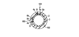
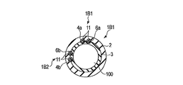
- FIG. 1 is a diagram schematically showing a bending sensor 1 according to the first embodiment.
- the bending sensor 1 has one cylindrical tube 1A and two sensor units 1B1 and 1B2.
- the cylinder 1 ⁇ / b> A includes a cylindrical first elastic member 2 and a cylindrical second elastic member 3.
- the inner diameter of the first elastic member 2 is set to be approximately the same as the outer diameter of the second elastic member 3.
- the second elastic member 3 is engaged with the second elastic member 3 on the outer side of the second elastic member 3, and the outer peripheral surface of the second elastic member 3 is joined to the inner peripheral surface of the first elastic member 2. Yes.
- a measured object 100 to be bent for example, a flexible endoscope having a flexible bending portion, forceps, or a catheter is inserted inside the second elastic member 3.
- the inner diameter of the second elastic member 3 is set so as to substantially match the outer diameter of the measurement object 100 to be inserted.
- the bending sensor 1 When the bending sensor 1 is attached to the object 100 to be bent, the inner peripheral surface of the second elastic member 3 is joined to the outer peripheral surface of the object 100 to be bent. At this time, the bending sensor 1 is held and fixed on the outer peripheral surface of the measurement object 100 which is bent by the elastic force of the first and second elastic members 2 and 3.
- FIG. 2 is a perspective view schematically showing a state in which the first elastic member 2 of the bending sensor 1 is removed.
- FIG. 3 is a cross-sectional view of the bending sensor 1 taken along line AA in FIG.
- the bending sensor 1 includes a light supply fiber 4 as a light supply unit, a sensor fiber 6 as a bending measurement unit provided with a bending state detection unit 5, and a reflecting member 7 as a light transmission unit.
- the light supply fiber 4, the sensor fiber 6, and the reflection member 7 are inserted between the first elastic member 2 and the second elastic member 3, and the elasticity of the first and second elastic members 2, 3. It is clamped and fixed by force. Furthermore, you may fix with the adhesive agent which is not shown in figure.
- the light supply fiber 4 and the sensor fiber 6 are, for example, optical fibers composed of a glass core and a resin cladding.
- the bending state detection unit 5 is provided with, for example, a notch in a clad at a predetermined position of the sensor fiber 6, and a resin having desired optical characteristics (for example, an absorber or a fluorescent material that absorbs light of a specific wavelength). Body).
- the reflection member 7 is disposed on the front end side in the longitudinal direction of the light supply fiber 4 and the sensor fiber 6, and reflects the light guided from the light supply fiber 4 to the sensor fiber 6. That is, the light supply fiber 4 and the sensor fiber 6 are optically connected via the reflecting member 7.
- the reflecting member 7 is, for example, a prism that is a member that is composed of two orthogonal mirrors and reverses the direction of light by 180 °.
- a light source 8 is connected to the base end side in the longitudinal direction of the light supply fiber 4.
- the light source 8 is, for example, a laser light source, and emits laser light having a predetermined wavelength to the light supply fiber 4.
- a photodetector 9 is connected to the proximal end side of the sensor fiber 6 in the longitudinal direction.
- the photodetector 9 receives the light guided through the light supply fiber 4, reflected by the reflecting member 7, and guided through the sensor fiber 6. That is, the photodetector 9 is a light receiving unit that receives an optical signal (curved signal) related to the curved state from the sensor fiber 6.
- 1 to 3 show two light supply fibers 4a and 4b, two sensor fibers 6a and 6b provided with curved state detection sections 5a and 5b, respectively, and two reflecting members 7a and 7b. It is shown.
- Light sources 8a and 8b are connected to the proximal ends of the light supply fibers 4a and 4b, respectively.
- photodetectors 9a and 9b are connected to the proximal ends of the sensor fibers 6a and 6b, respectively.
- the bending state detection unit 5 a and the bending state detection unit 5 b are located at positions orthogonal to each other in the radial direction of the bending sensor 1, that is, in the direction of the center line O of the cylindrical body 1 ⁇ / b> A of the bending sensor 1. In the plane orthogonal to each other, they are arranged in the X-axis direction and the Y-axis direction orthogonal to the center line O, and detect a vertical curve and a horizontal curve, respectively. That is, the bending sensor 1 can measure the bending in the biaxial directions orthogonal to each other by the bending state detection units 5a and 5b.
- the positional relationship between the bending state detection unit 5a and the bending state detection unit 5b is not limited to 90 °, and the bending state detection units 5a and 5b are arranged in a positional relationship other than 90 °. Also good. Further, for example, only the bending state detection unit 5a may be configured to measure bending in one axis direction.
- the bent measuring object 100 When detecting the bending state of the bent measuring object 100, first, the bent measuring object 100 is inserted inside the second elastic member 3 of the bending sensor 1, and the first and second elastic members are inserted.
- the bending sensor 1 is attached to the outer peripheral surface of the measurement object 100 that is bent by a few elastic forces.
- the first and second elastic members 2, 3 hold the bending detection mechanism including the light supply fiber 4, the sensor fiber 6, and the reflection member 7 at a predetermined position on the measurement object 100 that bends ( It functions as a holding member.
- the light emitted from the light source 8 is guided through the light supply fiber 4, reflected by the reflecting member 7 disposed on the distal end side of the light supply fiber 4, and the reflected light is guided to the sensor fiber 6. Furthermore, when the reflected light passes through the bending state detection unit 5 of the sensor fiber 6, the amount of light leaking from the bending state detection unit 5 to the outside changes according to the bending angle and the bending direction. The changed amount of light is received by the photodetector 9 on the proximal end side of the sensor fiber 6. Thus, the bending state of the measurement object 100 to be bent in the vicinity of the bending state detection unit 5 is detected. In other words, the bending state of the object 100 to be bent can be measured by the change in the amount of light output through the bending state detection unit 5.
- the device under test 100 in which the sensor fiber 6 provided with the light supply fiber 4 and the bending state detection unit 5 is bent by the elastic force of the first elastic member 2 and the second elastic member 3. Held in place above.
- the bending detection mechanism including the bending state detection unit to the object to be bent, and to provide a bending sensor that can be mounted widely and generally even if the object to be measured has a relatively small diameter. can do.
- the curvature sensor of the present embodiment can be mounted not on the endoscope, such as an endoscope forceps channel, but on the outer peripheral surface of the endoscope. Therefore, even if the measurement object to be bent does not include a through-hole extending in the longitudinal direction such as a forceps channel, the bending sensor can be easily incorporated into the measurement object to be bent.
- an endoscope provided with a forceps channel
- a bladder endoscope water is supplied / drained from the forceps channel to the bladder, and the bending state of the endoscope is monitored to grasp where the endoscope is facing the bladder. Work to do.
- the user can freely attach and detach the bending sensor to the existing object to be bent.
- the bending sensor can be retrofitted without purchasing another object to be bent again.
- the bending sensor can be detached from the measurement object to be bent by the user, that is, the holder can be attached to and detached from the measurement object to be bent. Therefore, the bending sensor can return to a state in which it does not have a measurement object to be bent, that is, there is an effect that the options of the user are expanded.
- the light supply unit and the bending measurement unit are held at predetermined positions of the holding unit regardless of whether the holding unit is attached to or detached from the measurement object to be bent.
- a bending sensor when a bending sensor is attached to a measuring object having a relatively small diameter, the thinner the measuring object to be bent, the more mechanical or optical to the bending due to the rigidity of the constituent members of the retrofitting bending sensor. Adverse effects cannot be ignored. According to the present embodiment, it is possible to provide a bending sensor that can be mounted without obstructing the bendability of a measured object having a relatively small diameter. Furthermore, the bending state detection unit can be appropriately protected by the first and second elastic members as the holding unit.
- a maker may attach a curvature sensor to the existing to-be-measured body previously, without leaving it to a user.
- the bending sensor may be fixed to a measurement object that bends with an adhesive, solder, or the like, so that the bending sensor cannot be attached to or detached from the measurement object to be bent.
- Such a configuration is preferable, for example, in consideration of the convenience of the user with respect to the measured object to be bent of the disposal or the ultra-small curved measured object.
- the cores of the light supply fiber 4 and the sensor fiber 6 are not limited to glass but may be made of resin. If these are made of resin, the elasticity of the fiber increases, so that the fiber tends to bend following the bending of the first elastic member 2 and the second elastic member 3. Therefore, when the bending sensor 1 is bent, it becomes difficult for the light supply fiber 4 and the sensor fiber 6 to inhibit the bending between the first elastic member 2 and the second elastic member 3. Thereby, it becomes easy to cope with a large bending angle.
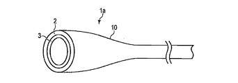
- FIG. 4 is a diagram schematically showing a curvature sensor 1a according to a first modification of the first embodiment.
- the bending sensor 1a has a tapered portion 10 on one end side.
- the tapered portion 10 gradually expands to a state in which the inner diameter increases as the first elastic member 2 and the second elastic member 3 move toward the end portion on one end side.
- the measured object 100 to be bent when the measured object 100 to be bent is inserted inside the second elastic member 3, the measured object 100 to be bent is guided to the expanded portion of the tapered portion 10. This facilitates the operation of inserting the measured object 100 to be bent inside the second elastic member 3.
- the tapered portion 10 may be provided not only on one end side of the bending sensor 1a but also on both end sides. Further, the tapered portion 10 may be cut on one end side of the first and second elastic members 2 and 3 so that the outer diameter of the tapered portion 10 does not become too large.
- the present invention is not limited to the tapered portion 10, and for example, a cut may be made at one end of each of the first and second elastic members 2 and 3 so that the one end is greatly elastically deformable. In this case as well, the work of inserting the measured object 100 to be curved inside the second elastic member 3 is facilitated.
- FIG. 5a and 5b are cross-sectional views showing a bending sensor 1b according to a second modification of the first embodiment.
- a thin circular elastic tube 11 is fixed between the first elastic member 2 and the second elastic member 3 with an adhesive (not shown).
- the light supply fibers 4 a and 4 b and the sensor fibers 6 a and 6 b are inserted through the elastic tube 11.
- the portions of the sensor fibers 6 a and 6 b where the detection unit 5 in the bent state is provided are not covered with the elastic tube 11.
- the inner diameter of the elastic tube 11 is larger than the outer diameters of the light supply fibers 4a and 4b and the sensor fibers 6a and 6b. Accordingly, the light supply fibers 4a and 4b and the sensor fibers 6a and 6b can slide in the elastic tube 11 in the optical axis direction (longitudinal direction) of the fiber.
- the elastic tube 11 does not extend to both ends of the first elastic member 2. Therefore, the light supply fibers 4a and 4b and the sensor fibers 6a and 6b are fixed to the first and second elastic members 2 and 3 by, for example, an adhesive at both ends thereof.
- the light supply fiber 4 and the sensor fiber 6 slide in the optical axis direction in the elastic tube 11, the light supply fiber 4 and the sensor fiber 6 are the first and second elastic members 2, 3. It is easy to bend following the curve. Therefore, it becomes difficult for the light supply fiber 4 and the sensor fiber 6 to inhibit the bending of the entire bending sensor 1b. Therefore, the bending sensor 1b can easily cope with a large bending angle.
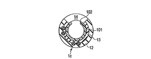
- FIG. 6 is a cross-sectional view showing a bending sensor 1c of a third modification of the first embodiment.
- the cross sections of the first and second elastic members 12 and 13 are not circular but C-shaped. That is, notches 14 are formed in the peripheral wall portions of the first and second elastic members 12 and 13.
- the notch 14 is formed in the first and second elastic members 12 and 13, so that the bending sensor 1c can be mounted from the side to the object to be bent. . For this reason, it is easy to attach the bending sensor 1c to the measurement object to be bent.
- This modification is particularly suitable when the elastic member is a metal spring material.
- the bending state detection unit 5 since the bending state detection unit 5 is disposed where the notch 14 is not provided, it is protected by the first and second elastic members 12 and 13 as the holding unit. Further, since the notches 14 are formed, the rigidity of the first and second elastic members 12 and 13 is reduced, and the bending is facilitated.
- the bending sensor 1c of the present modification is suitable for mounting on a measurement object having a smaller diameter than that of an endoscope, for example, a catheter punctured into a living tissue.
- FIG. 7 is a longitudinal sectional view schematically showing the catheter 101 to which the bending sensor 1c is attached.
- 8 is a cross-sectional view taken along the line CC of FIG.
- On the outer peripheral surface of the catheter 101 a through-hole 102 that penetrates the outer peripheral surface in the radial direction is formed.
- the through hole 102 is, for example, a discharge port for a drug or the like when a drug or the like is administered to a living tissue using the catheter 101 or a suction port for sucking a body fluid or the like from the living tissue.
- the cutouts 14 of the first and second elastic members 12 and 13 of the bending sensor 1c and the through-hole 102 of the catheter 101 are arranged so that the bending sensor 1c does not cover the through-hole 102 of the catheter 101.
- the bend sensor 1c is attached to the catheter 101 after alignment.
- the through hole 102 of the catheter 101 and the notch 14 of the curvature sensor 1c are aligned and mounted, so that the curvature sensor 1c of this modification can be attached to the catheter 101 without impeding the function of the catheter 101. Can be applied.
- FIG. 9 is a diagram schematically illustrating a bending sensor 1d according to a fourth modification of the first embodiment.
- the cylinder 1A is separated into a distal end side cylinder 15a and a proximal end side cylinder 15b. That is, the cylinders as holding members made of an elastic member are separated from each other.
- the bending state detection part 5 of the sensor fiber 6 is located in at least one of the front end side cylinder 15a and the base end side cylinder 15b.
- the distal end side cylinder 15a and the proximal end side cylinder 15b are connected by a light supply fiber 4 and a sensor fiber 6 that are sandwiched and fixed between them.
- an elastic member as a holding portion is not provided in a part of the light supply fiber 4 and the sensor fiber 6, for example, a portion of the sensor fiber 6 where the bending state detection unit 5 is not provided.
- the rigidity of the portion is reduced. Accordingly, the bending property of the bending sensor can be improved by the amount of reduced rigidity.
- the bending state detection unit is protected by the first and second elastic members as the holding unit.
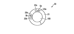
- (Second Embodiment) 10 and 11 are diagrams showing the bending sensor 20 of the second embodiment.
- a part of the light supply fibers 4a and 4b in the first embodiment is replaced with light supply paths 22a and 22b formed of a core and a clad provided on the flexible optical wiring board 21.
- a part of the sensor fibers 6a and 6b including at least the bending state detection units 5a and 5b in the first embodiment is replaced with the sensor paths 23a and 23b formed of the core and the clad provided on the flexible optical wiring board 21.
- the light supply paths 22a and 22b and the light supply fibers 4a and 4b, and the sensor paths 23a and 23b and the sensor fibers 6a and 6b are optically coupled by fusion or the like.
- the first and second elastic members 2 and 3 in the first embodiment are unnecessary.
- the flexible optical wiring board 21 holds the bending detection mechanism including the bending state detection unit 5 at a predetermined position on the object 100 to be bent. It functions as a part.
- the flexible optical wiring board 21 In general, it is difficult to produce the flexible optical wiring board 21 long enough to accommodate the endoscope in the longitudinal direction (optical axis direction) of the bending sensor 20 (for example, a length of about 1 m) for reasons such as cost. is there. Therefore, as shown in FIG. 11, the light supply fibers 4a and 4b and the sensor fibers 6a and 6b are added to the flexible optical wiring board 21 as extension optical fibers. Thereby, even when the length of the flexible optical wiring board 21 is smaller than the required length, the length of the bending sensor 20 can be extended to the required length, which is advantageous in terms of cost and the like.
- the positional relationship between the two bending state detection units 5a and 5b is determined by the accuracy of the distance between the two sensor paths 23a and 23b of the flexible optical wiring board 21, the two sensor paths 23a, It is not necessary to align the position of 23b. Further, it is not necessary to match the positional relationship of the two bending state detection units 5a and 5b with respect to the circumferential direction of the bending sensor 20. Therefore, the assembly process of the bending sensor 20 can be simplified.
- the bending state detection unit is protected by the flexible optical wiring board.
- the flexible optical wiring board has a function of bundling the light supply path and the sensor path and a function of holding the light supply path and the sensor path with respect to the flexible optical wiring board. Since the flexible optical wiring board fulfills these two functions with a single member, it is not necessary to increase the number of components of the bending sensor. Therefore, the rigidity of the bending sensor can be reduced, and the bending of the bending sensor becomes easy.
- the core and the clad are made of resin, it becomes easy to provide a bending sensor with further improved bendability.
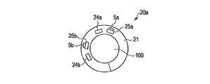
- FIG. 12 is a cross-sectional view showing a bending sensor 20a according to a modification of the second embodiment.
- the flexible optical wiring board 21 is not limited to a type using a light supply path and a sensor path of an optical fiber composed of a core and a clad.
- the flexible optical wiring board 21 is, for example, a flexible optical wiring board using light supply paths 24a and 24b made of optical waveguides and sensor paths 25a and 25b made of optical waveguides.
- the sensor paths 25a and 25b are respectively provided with bending state detection units 5a and 5b that are manufactured in advance at a part of the sensor paths 25a and 25b by printing or the like at the time of manufacture.
- FIG. 13 is a diagram schematically illustrating the bending sensor 30 of the third embodiment.
- the light supply fiber 4 and the sensor fiber 6 are configured by a single optical fiber. Therefore, the bending sensor 30 does not have the reflecting member 7 in the first embodiment, and is formed with folded portions 31 (31a, 31b) in which one optical fiber is bent in the middle thereof. That is, the folded portion 31 optically connects the light supply fiber 4 and the sensor fiber 6 without using the reflecting member 7.
- the present invention is not limited to this, and the bending sensor may be configured by a flexible optical wiring board in which the folded portion 31 is formed in advance.
- the present embodiment since there is no reflecting member, there is no reflection loss of light guided through the optical fiber, and a curved sensor with good sensitivity can be provided.
- the configuration of the bending sensor can be further simplified, it is easy to reduce the size and cost of the bending sensor.
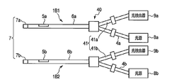
- (Fourth embodiment) 14 and 15 are diagrams showing a curvature sensor 40 of the fourth embodiment.
- the light supply fiber 4 and the sensor fiber 6 are connected by an optical coupler 41 (41a, 41b), and the light supply fiber 4 and the sensor fiber 6 become one optical fiber from the middle and are shared.
- a reflection member 7 (7a, 7b) is disposed on the tip side of the single sensor fiber 6 (6a, 6b).
- the light guided through the light supply fiber 4 passes through the optical coupler 41 and the sensor fiber 6, and the reflected light reflected by the reflecting member 7 guides the sensor fiber 6 and passes through the optical coupler 41.
- the light is received by the photodetector 9.
- the photodetector 9 measures the amount of light that reflects the amount of light that changes in the bending state detection unit 5 in accordance with the bending state of the sensor fiber 6, and detects the bending state.
- the light supply fiber and the sensor fiber are shared from the middle, and at least a part of the sensor fiber also serves as the light supply fiber, so that the number of fibers is reduced. This facilitates downsizing the curvature sensor. Moreover, since there are few fibers to use, it can manufacture at low cost. Further, the bending state detection unit is protected by first and second elastic members as holding units.
- the rigidity of the light supply fiber is difficult to prevent the measured object from bending. Furthermore, it is easy to realize a bending sensor corresponding to a large bending angle.
- FIG. 16 is a diagram schematically illustrating the second elastic member 51 of the bending sensor 50 according to the fifth embodiment.
- the second elastic member 51 of the bending sensor 50 includes a first region 52 and a second region 53 having different diameters.
- the first region 52 is formed by a small diameter portion having a first diameter r having a small diameter.
- the second region 53 is formed by a large diameter portion having a second diameter R (r ⁇ R) larger than the first diameter r.
- the first region 52 is a region where the bending state detection unit 5 of the sensor fiber 6 is disposed
- the second region 53 is a region where the bending state detection unit 5 is not disposed, that is, the bending state detection unit 5 and This is a region different from the region where is placed.
- the object to be measured which is inserted inside the second elastic member 51, is held with a stronger elastic force than the second region 53.
- the object to be measured is held with a relatively weak elastic force.
- the inner peripheral surface of the first elastic member engaged with the outer peripheral surface of the second elastic member 51 substantially conforms to the shape of the second outer peripheral surface, and the first and second elastic members A bending detection mechanism including a light supply fiber and a sensor fiber is sandwiched and fixed between the members.
- the curved state detection unit is provided with the region fixed by the relatively strong elastic force on the measurement object to bend, so that an accurate curved state can be measured, and at the same time, a large It is possible to easily cope with the bending angle.
- the optical fiber is held with a relatively weak elastic force, so that the optical fiber can slide in the area. For this reason, the curve is easy.
- FIG. 17 and 18 are views showing the first elastic member 61 of the bending sensor 60 of the sixth embodiment.
- the first elastic member 61 and the second elastic member are formed with at least one slit 63 penetrating the peripheral wall portions of these elastic members in the radial direction.
- the slits 63 are arranged at predetermined intervals in the circumferential direction of the first elastic member 61 and the second elastic member.
- the shape of the slit 63 is rectangular in FIG. 17, but may be circular, elliptical, or the like.
- the slit 63 is formed at a position different from the curved state detection unit 5 in the longitudinal direction of the first elastic member 61 and the second elastic member.
- the slit 63 may be provided only in one of the first elastic member 61 and the second elastic member.
- the slit is formed at a position different from the position where the bending state detection unit of the first and second elastic members is disposed (the position where the bending state detection unit is not provided).
- the rigidity of the elastic member becomes low and the bending becomes easy. Further, the bending state detection unit can be appropriately protected by the first and second elastic members.
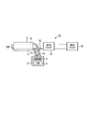
- FIG. 19 is a diagram schematically illustrating one aspect of the curvature sensor 70 of the seventh embodiment.
- the bending sensor 70 includes an optical fiber 71 that connects the light supply fiber 4 and the light source 8, and an optical fiber 72 that connects the sensor fiber 6 and the photodetector 9.
- the optical fibers 71 and 72 are connected to the first driver 75 by optical connectors 73 and 74, respectively.
- the first driver 75 is further connected to a second driver 76 including the light source 8 and the photodetector 9.
- the bending sensor can be easily mounted on the object to be bent.
- the bending sensor can be attached to and detached from the object to be bent with a connector, the bending state detection unit can be easily cleaned.
- FIG. 20 is a diagram schematically showing another aspect of the bending sensor 70 of the seventh embodiment.
- the optical fiber 71 and the optical fiber 72 may be bundled with a binding tool 78 on the way.
- the light source 8 and the photodetector 9 may be housed in a separate case 77.
- optical fibers are bundled, handling by the operator is easy. Moreover, in this aspect, it is not necessary to previously incorporate a light source or a light detector into the object to be bent, and a more versatile bending sensor can be provided.
- curve sensor DESCRIPTION OF SYMBOLS 41 ... Optical coupler, 50 ... Curve sensor, 51 ... 2nd elastic member, 52 ... 1st area
Landscapes
- Physics & Mathematics (AREA)
- Health & Medical Sciences (AREA)
- Life Sciences & Earth Sciences (AREA)
- Surgery (AREA)
- Optics & Photonics (AREA)
- General Physics & Mathematics (AREA)
- Biomedical Technology (AREA)
- Molecular Biology (AREA)
- Pathology (AREA)
- Veterinary Medicine (AREA)
- Biophysics (AREA)
- Engineering & Computer Science (AREA)
- Public Health (AREA)
- Heart & Thoracic Surgery (AREA)
- Medical Informatics (AREA)
- General Health & Medical Sciences (AREA)
- Animal Behavior & Ethology (AREA)
- Nuclear Medicine, Radiotherapy & Molecular Imaging (AREA)
- Radiology & Medical Imaging (AREA)
- Astronomy & Astrophysics (AREA)
- Dentistry (AREA)
- Oral & Maxillofacial Surgery (AREA)
- Endoscopes (AREA)
- Instruments For Viewing The Inside Of Hollow Bodies (AREA)
- Length Measuring Devices By Optical Means (AREA)
Abstract
L'invention concerne un détecteur de courbe pouvant être appliqué largement et de manière universelle, même à des objets à mesurer qui ne présentent qu'une courbure relativement faible. Dans une forme de réalisation, la présente invention concerne un détecteur de courbe permettant de mesurer la courbe d'un objet courbé devant être mesuré, ledit détecteur de courbe comportant une partie d'apport de lumière, qui permet de conduire la lumière, et une partie détection d'état de courbe. Ce détecteur de courbe comprend : une partie de mesure de courbe, qui permet de mesurer l'état de courbe d'un objet à mesurer au moyen de la variation de la quantité de lumière traversant la partie de détection d'état de courbe et qui sort de celle-ci; une partie de transmission de lumière, qui transmet la lumière provenant de la partie d'apport de lumière à la partie de mesure de courbe; et une partie de retenue, qui retient la partie d'apport de lumière et la partie de mesure de courbe dans une position spécifique sur l'objet à mesurer.
Priority Applications (3)
| Application Number | Priority Date | Filing Date | Title |
|---|---|---|---|
| CN201380027015.0A CN104334070B (zh) | 2012-06-20 | 2013-06-19 | 弯曲传感器 |
| EP13807866.2A EP2865317A4 (fr) | 2012-06-20 | 2013-06-19 | Détecteur de courbe |
| US14/570,176 US9766059B2 (en) | 2012-06-20 | 2014-12-15 | Curve sensor |
Applications Claiming Priority (2)
| Application Number | Priority Date | Filing Date | Title |
|---|---|---|---|
| JP2012138925A JP5963563B2 (ja) | 2012-06-20 | 2012-06-20 | 湾曲センサ |
| JP2012-138925 | 2012-06-20 |
Related Child Applications (1)
| Application Number | Title | Priority Date | Filing Date |
|---|---|---|---|
| US14/570,176 Continuation US9766059B2 (en) | 2012-06-20 | 2014-12-15 | Curve sensor |
Publications (1)
| Publication Number | Publication Date |
|---|---|
| WO2013191214A1 true WO2013191214A1 (fr) | 2013-12-27 |
Family
ID=49768808
Family Applications (1)
| Application Number | Title | Priority Date | Filing Date |
|---|---|---|---|
| PCT/JP2013/066869 WO2013191214A1 (fr) | 2012-06-20 | 2013-06-19 | Détecteur de courbe |
Country Status (5)
| Country | Link |
|---|---|
| US (1) | US9766059B2 (fr) |
| EP (1) | EP2865317A4 (fr) |
| JP (1) | JP5963563B2 (fr) |
| CN (1) | CN104334070B (fr) |
| WO (1) | WO2013191214A1 (fr) |
Families Citing this family (9)
| Publication number | Priority date | Publication date | Assignee | Title |
|---|---|---|---|---|
| US9645570B2 (en) * | 2013-03-22 | 2017-05-09 | Pegatron Corporation | Monitoring system |
| TWI476554B (zh) * | 2013-03-22 | 2015-03-11 | Pegatron Corp | 監控系統 |
| WO2016163030A1 (fr) * | 2015-04-10 | 2016-10-13 | オリンパス株式会社 | Capteur à fibres |
| CN107613834B (zh) * | 2015-05-29 | 2019-08-02 | 奥林巴斯株式会社 | 曲率传感器和搭载有该曲率传感器的内窥镜装置 |
| JP2018018720A (ja) * | 2016-07-28 | 2018-02-01 | パナソニックIpマネジメント株式会社 | 発光装置、および、発光装置の点検方法 |
| DE102018105132B4 (de) * | 2018-03-06 | 2023-07-13 | Haag-Streit Gmbh | Triangulationsvorrichtung |
| US11214120B2 (en) * | 2018-11-02 | 2022-01-04 | Continental Automotive Systems, Inc. | Distributed fiber optic sensing system |
| CN110095086A (zh) * | 2019-06-03 | 2019-08-06 | 呜啦啦(广州)科技有限公司 | 电流式双向弯曲传感器及其制备方法 |
| CN111678465B (zh) * | 2020-05-28 | 2021-12-10 | 哈尔滨工业大学 | 一种基于超声导波的管道弯曲检测方法 |
Citations (4)
| Publication number | Priority date | Publication date | Assignee | Title |
|---|---|---|---|---|
| JPH0591972A (ja) * | 1991-10-02 | 1993-04-16 | Toshiba Corp | 湾曲表示装置 |
| JP2005027725A (ja) * | 2003-07-07 | 2005-02-03 | Olympus Corp | 超音波診断装置 |
| JP2007044405A (ja) * | 2005-08-12 | 2007-02-22 | Pentax Corp | 内視鏡挿入形状検出プローブ |
| JP2007044412A (ja) | 2005-08-12 | 2007-02-22 | Pentax Corp | 内視鏡挿入形状検出プローブ |
Family Cites Families (16)
| Publication number | Priority date | Publication date | Assignee | Title |
|---|---|---|---|---|
| ATE159586T1 (de) * | 1993-06-10 | 1997-11-15 | Lee A Danisch | Faseroptischer biege- und positionierungssensor |
| JP4005318B2 (ja) | 2001-02-28 | 2007-11-07 | ペンタックス株式会社 | 可撓性内視鏡装置 |
| JP3898910B2 (ja) | 2001-05-31 | 2007-03-28 | ペンタックス株式会社 | 可撓性内視鏡装置 |
| JP3881525B2 (ja) | 2001-05-22 | 2007-02-14 | ペンタックス株式会社 | 可撓性内視鏡装置 |
| JP3881526B2 (ja) | 2001-05-22 | 2007-02-14 | ペンタックス株式会社 | 可撓性内視鏡装置 |
| WO2004056017A1 (fr) * | 2002-12-16 | 2004-07-01 | Aston Photonic Technologies Limited | Systeme optique d'interrogation et systeme detecteur |
| DE102004017834B4 (de) * | 2004-04-13 | 2011-01-27 | Siemens Ag | Kathetereinrichtung |
| DE602004021377D1 (de) * | 2004-08-27 | 2009-07-16 | Schlumberger Holdings | Sensor und Vermessungsvorrichtung zur Bestimmung des Biegeradius und der Form eines Rohrleitungs |
| JP4714570B2 (ja) * | 2005-11-24 | 2011-06-29 | Hoya株式会社 | 内視鏡形状検出プローブ |
| US8989528B2 (en) * | 2006-02-22 | 2015-03-24 | Hansen Medical, Inc. | Optical fiber grating sensors and methods of manufacture |
| GB0620944D0 (en) * | 2006-10-20 | 2006-11-29 | Insensys Ltd | Curvature measurement moving relative to pipe |
| JP4580973B2 (ja) * | 2007-11-29 | 2010-11-17 | オリンパスメディカルシステムズ株式会社 | 処置具システム |
| US8886334B2 (en) * | 2008-10-07 | 2014-11-11 | Mc10, Inc. | Systems, methods, and devices using stretchable or flexible electronics for medical applications |
| EP2351509A4 (fr) * | 2008-10-28 | 2018-01-17 | Olympus Corporation | Dispositif médical |
| US9387048B2 (en) * | 2011-10-14 | 2016-07-12 | Intuitive Surgical Operations, Inc. | Catheter sensor systems |
| US9062960B2 (en) * | 2012-02-07 | 2015-06-23 | Medlumics S.L. | Flexible waveguides for optical coherence tomography |
-
2012
- 2012-06-20 JP JP2012138925A patent/JP5963563B2/ja not_active Expired - Fee Related
-
2013
- 2013-06-19 WO PCT/JP2013/066869 patent/WO2013191214A1/fr unknown
- 2013-06-19 CN CN201380027015.0A patent/CN104334070B/zh active Active
- 2013-06-19 EP EP13807866.2A patent/EP2865317A4/fr not_active Withdrawn
-
2014
- 2014-12-15 US US14/570,176 patent/US9766059B2/en active Active
Patent Citations (4)
| Publication number | Priority date | Publication date | Assignee | Title |
|---|---|---|---|---|
| JPH0591972A (ja) * | 1991-10-02 | 1993-04-16 | Toshiba Corp | 湾曲表示装置 |
| JP2005027725A (ja) * | 2003-07-07 | 2005-02-03 | Olympus Corp | 超音波診断装置 |
| JP2007044405A (ja) * | 2005-08-12 | 2007-02-22 | Pentax Corp | 内視鏡挿入形状検出プローブ |
| JP2007044412A (ja) | 2005-08-12 | 2007-02-22 | Pentax Corp | 内視鏡挿入形状検出プローブ |
Non-Patent Citations (1)
| Title |
|---|
| See also references of EP2865317A4 |
Also Published As
| Publication number | Publication date |
|---|---|
| JP2014000312A (ja) | 2014-01-09 |
| EP2865317A1 (fr) | 2015-04-29 |
| CN104334070A (zh) | 2015-02-04 |
| US9766059B2 (en) | 2017-09-19 |
| EP2865317A4 (fr) | 2016-03-02 |
| CN104334070B (zh) | 2017-03-15 |
| JP5963563B2 (ja) | 2016-08-03 |
| US20150100000A1 (en) | 2015-04-09 |
Similar Documents
| Publication | Publication Date | Title |
|---|---|---|
| WO2013191214A1 (fr) | Détecteur de courbe | |
| JP6270347B2 (ja) | 形状センサ | |
| US10307211B2 (en) | Multipoint detection fiber sensor and insertion apparatus including multipoint detection fiber sensor | |
| EP3032217A1 (fr) | Capteur optique, système de capteur optique et endoscope | |
| US10064542B2 (en) | Bending apparatus with bending direction restriction mechanism | |
| WO2015163210A1 (fr) | Dispositif d'endoscope | |
| US10436578B2 (en) | Endoscope apparatus | |
| JP2007044412A (ja) | 内視鏡挿入形状検出プローブ | |
| JP6108844B2 (ja) | 形状センサ | |
| CN107250864B (zh) | 光纤电缆组件及测定装置 | |
| JP6461343B2 (ja) | 形状検出装置 | |
| JP6447038B2 (ja) | 光コネクタ結合システム | |
| CN106061352A (zh) | 内窥镜 | |
| WO2017208402A1 (fr) | Dispositif de détection de forme | |
| JP2017040703A (ja) | 光モジュール及び光モジュール用レセプタクル | |
| JP2005188971A (ja) | 保持具、光学測定装置、及び光学測定方法 |
Legal Events
| Date | Code | Title | Description |
|---|---|---|---|
| 121 | Ep: the epo has been informed by wipo that ep was designated in this application |
Ref document number: 13807866 Country of ref document: EP Kind code of ref document: A1 |
|
| NENP | Non-entry into the national phase |
Ref country code: DE |