WO2013187488A1 - Unité de rouleau de puissance, son procédé de fabrication et transmission à variation continue semi-toroïdale - Google Patents
Unité de rouleau de puissance, son procédé de fabrication et transmission à variation continue semi-toroïdale Download PDFInfo
- Publication number
- WO2013187488A1 WO2013187488A1 PCT/JP2013/066387 JP2013066387W WO2013187488A1 WO 2013187488 A1 WO2013187488 A1 WO 2013187488A1 JP 2013066387 W JP2013066387 W JP 2013066387W WO 2013187488 A1 WO2013187488 A1 WO 2013187488A1
- Authority
- WO
- WIPO (PCT)
- Prior art keywords
- outer ring
- power roller
- support beam
- trunnion
- pair
- Prior art date
Links
Images


Classifications
-
- F—MECHANICAL ENGINEERING; LIGHTING; HEATING; WEAPONS; BLASTING
- F16—ENGINEERING ELEMENTS AND UNITS; GENERAL MEASURES FOR PRODUCING AND MAINTAINING EFFECTIVE FUNCTIONING OF MACHINES OR INSTALLATIONS; THERMAL INSULATION IN GENERAL
- F16H—GEARING
- F16H15/00—Gearings for conveying rotary motion with variable gear ratio, or for reversing rotary motion, by friction between rotary members
- F16H15/02—Gearings for conveying rotary motion with variable gear ratio, or for reversing rotary motion, by friction between rotary members without members having orbital motion
- F16H15/04—Gearings providing a continuous range of gear ratios
- F16H15/06—Gearings providing a continuous range of gear ratios in which a member A of uniform effective diameter mounted on a shaft may co-operate with different parts of a member B
- F16H15/32—Gearings providing a continuous range of gear ratios in which a member A of uniform effective diameter mounted on a shaft may co-operate with different parts of a member B in which the member B has a curved friction surface formed as a surface of a body of revolution generated by a curve which is neither a circular arc centered on its axis of revolution nor a straight line
- F16H15/36—Gearings providing a continuous range of gear ratios in which a member A of uniform effective diameter mounted on a shaft may co-operate with different parts of a member B in which the member B has a curved friction surface formed as a surface of a body of revolution generated by a curve which is neither a circular arc centered on its axis of revolution nor a straight line with concave friction surface, e.g. a hollow toroid surface
- F16H15/38—Gearings providing a continuous range of gear ratios in which a member A of uniform effective diameter mounted on a shaft may co-operate with different parts of a member B in which the member B has a curved friction surface formed as a surface of a body of revolution generated by a curve which is neither a circular arc centered on its axis of revolution nor a straight line with concave friction surface, e.g. a hollow toroid surface with two members B having hollow toroid surfaces opposite to each other, the member or members A being adjustably mounted between the surfaces
Definitions
- the present invention relates to a half-toroidal continuously variable transmission, particularly a trunnion that is swingably supported by the half-toroidal continuously variable transmission, and a half-toroidal continuously variable transmission that is used as a transmission for a vehicle such as an automobile.
- the present invention relates to a power roller unit including at least an outer ring that constitutes a thrust rolling bearing for rotatably supporting a power roller that is sandwiched between an input disk and an output disk and that transmits torque with respect to a trunnion.
- CVT continuously variable continuously variable transmission
- a half-toroidal continuously variable transmission that realizes a continuously variable transmission by changing the inclination angle of a power roller sandwiched between an input disk and an output disk.
- a half-toroidal continuously variable transmission, a planetary gear mechanism, and a clutch device are combined to increase the adjustment range of the transmission ratio of the entire transmission (see JP 2004-169719 A).
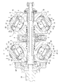
- FIGS. 18 and 19 show a first example of a conventional half-toroidal continuously variable transmission.
- a pair of input disks 2 are supported around a portion near both ends of the input rotation shaft 1 so as to be able to rotate in synchronization with the input rotation shaft 1.
- An output cylinder 3 is supported around the intermediate portion of the input rotation shaft 1 so as to be rotatable with respect to the input rotation shaft 1.
- An output gear 4 is fixed at the axial center of the outer peripheral surface of the output cylinder 3, and a pair of output disks 5 are rotated in synchronization with the output cylinder 3 by spline engagement at both axial ends. Is supported by possible.
- each combination of the input disk 2 and the output disk 5 the inner surface of the input disk 2 and the inner surface of the output disk 5 are opposed to each other, each of which is a toroidal curved surface.
- a plurality of power rollers 6 each having a spherical convex surface are sandwiched between the input disk 2 and the output disk 5.
- Each of these power rollers 6 is rotatably supported by the trunnion 7.
- Each trunnion 7 includes a pair of tilting shafts 8 provided concentrically with each other at both ends in the axial direction, and support beam portions 9 that connect these tilting shafts 8.
- the tilting shaft 8 of the trunnion 7 is pivotally supported via a radial needle bearing 11 with respect to the support plate 10 so as to be in a twisted position with respect to the center axis of the input disc 2 and the output disc 5.
- the rocking displacement is possible around the tilting axis 8.
- Each power roller 6 includes a support shaft 12 in which the base half and the front half are eccentric from each other on the inner side surface of the support beam portion 9 of the trunnion 7, and between the support beam portion 9 and the outer surface of the power roller 6.
- the thrust ball bearing 13 and the thrust needle bearing 14 provided in order from the power roller 6 side, the rotation about the front half of the support shaft 12 and the base half of the support shaft 12 are centered. It is supported so that a slight swing displacement is possible.
- the thrust ball bearing 13 supports the rotation of the power roller 6 while supporting a load in the thrust direction applied to the power roller 6, and the inner ring raceway 15 formed on the outer surface of the power roller 6 and the inner ring 16
- the outer ring raceway 17 is formed on the side surface, and a plurality of balls 18 are provided between these raceways so as to be able to roll.
- the thrust needle bearing 14 supports the thrust load applied to the outer ring 16 of the thrust ball bearing 13 from the power roller 6, and the front half of the outer ring 16 and the support shaft 12 is centered on the base half of the support shaft 12. It is allowed to swing.
- the power roller unit, the trunnion 7, the thrust ball bearing 13, and the thrust needle bearing 14 constitute a power roller unit.
- one input disk 2 (left side in FIG. 18) is rotationally driven by the drive shaft 19 via the pressing device 20.
- the pair of input disks 2 supported at both ends of the input rotating shaft 1 rotate synchronously while being pressed toward each other.
- This rotation is transmitted to the output disk 5 through the power roller 6 and is taken out from the output gear 4.
- the trunnion 7 is displaced in the axial direction of the tilt shaft 8 by the hydraulic actuator 21.
- the input disk 2, the output disk 5, and the power roller 6 that are used for power transmission are elastically deformed based on the pressing force generated by the pressing device 20. And with this elastic deformation, the input disk 2 and the output disk 5 are displaced in the axial direction. Further, the pressing force generated by the pressing device 20 increases as the torque transmitted by the half-toroidal continuously variable transmission increases, and the elastic deformation amount of the input disk 2, the output disk 5, and the power roller 6 increases accordingly. . Therefore, in order to maintain the contact state between the inner surface of the input disk and the output disk 5 and the peripheral surface of the power roller 6 regardless of torque fluctuation, the power roller 6 is connected to the trunnion 7 with respect to the input disk 2.
- a mechanism for displacing the output disk 5 in the axial direction is required.
- the front half of the support shaft 12 that supports the power roller 6 is oscillated and displaced about the base half thereof, so that the power roller 6 is moved to the shafts of the input disk 2 and the output disk 5. It is displaced in the direction.
- such a structure is complicated, and the production of the parts of the power roller unit, the parts management, and the assembly work are all complicated, and the manufacturing cost of the half-toroidal continuously variable transmission increases.
- Japanese Patent Laid-Open No. 2008-25821 discloses a second example of a conventional structure in which the structure for displacing the power roller in the axial direction of the input disk and the output disk is improved in order to solve such a problem.
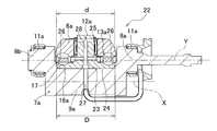
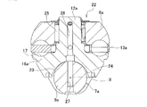
- the trunnion 7a constituting the second example of the conventional structure includes a pair of tilting shafts 8a and 8b concentrically provided at both ends, and these tilting shafts 8a, 8b, and a cylindrical convex surface 23 on the inner side (upper side in FIGS. 24 and 25) in the radial direction (the vertical direction in FIGS. 24 and 25) of at least the input disk 2 and the output disk 5 And a beam portion 9a.
- the tilting shafts 8a and 8b are supported on the support plate 10 (see FIG. 19) via a radial needle bearing 11a, respectively, so as to be swingable and axially displaceable.
- the center axis X of the cylindrical convex surface 23 is parallel to the center axis Y of the tilt axes 8a and 8b, and is more than the center axis Y of these tilt axes 8a and 8b.
- a concave portion 24 having a partially cylindrical surface is formed on the outer surface of the outer ring 16a constituting the thrust ball bearing 13a provided between the support beam portion 9a and the outer surface of the power roller 6a so as to cross the outer surface in the radial direction. Is provided.
- the outer ring 16a supports the trunnion 7a so as to be able to swing and displace in the axial direction of the input disk 2 and the output disk 5. Is done.
- the support shaft 12a is provided integrally with the outer ring 16a at the center of the inner surface of the outer ring 16a, and the power roller 6a is rotatably supported around the support shaft 12a via a radial needle bearing 25.
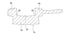
- a pair of stepped surfaces 26 facing each other are provided on the inner surface of the trunnion 7a at a continuous portion between both ends of the support beam portion 9a and the pair of tilting shafts 8a and 8b.
- These step surfaces 26 and the outer peripheral surface of the outer ring 16a of the thrust ball bearing 13a are brought into contact with or in close proximity to each other, and the traction force applied from the power roller 6a to the outer ring 16a is at any step surface 26. It comes to be supported.
- the power roller unit 22 is configured by the power roller 6a, the trunnion 7a, the thrust ball bearing 13a, and the radial needle bearing 25.
- the power roller 6a is displaced in the axial direction of the input disk 2 and the output disk 5, regardless of changes in the amount of elastic deformation of these constituent members.
- a structure capable of appropriately maintaining the contact state between the peripheral surface of the power roller 6a and the input disk 2 and the output disk 5 is realized simply and at low cost. That is, when the half-toroidal continuously variable transmission is operated, it is necessary to displace the power roller 6a in the axial direction of the input disk 2 and the output disk 5 based on elastic deformation of the input disk 2, the output disk 5, and the power roller 6a.
- the outer ring 16a of the thrust ball bearing 13a that rotatably supports the power roller 6a slides on the contact surface between the concave portion 24 of the partial cylindrical surface provided on the outer surface and the cylindrical convex surface 23 of the support beam portion 9a. In this manner, the cylindrical convex surface 23 is oscillated and displaced about the central axis X. Based on this oscillating displacement, a portion of the peripheral surface of the power roller 6a that is in rolling contact with one axial side surface of the input disk 2 and the output disk 5 is displaced in the axial direction of the input disk 2 and the output disk 5. The contact state between these components is properly maintained.
- the center axis X of the cylindrical convex surface 23 exists outside the center axis Y of the tilting shafts 8a and 8b, which are the center of oscillation of the trunnion 7a during the speed change operation, in the radial direction of the input disk 2 and the output disk 5. To do. Accordingly, since the radius of the rocking displacement around the central axis X of the cylindrical convex surface 23 is larger than the rocking radius at the time of the shifting operation, the power roller 6a having the central axis X of the cylindrical convex surface 23 as the center. The influence of the rocking displacement on the fluctuation of the transmission ratio between the input disk 2 and the output disk 5 is negligible or can be easily corrected.
- the distance D between the step surfaces 26 provided in pairs at both ends of the support beam portion 9a in order to smoothly swing and displace the outer ring 16a around the support beam portion 9a. Is slightly larger than the outer diameter d of the outer ring 16a (D> d). Therefore, the outer ring 16a and the power roller 6a can be displaced in the axial direction of the support beam portion 9a by the difference (D ⁇ d) between the distance D and the outer diameter d.
- the shift operation that is started for such a cause is a shift operation that is not directly related to the driving operation, and even if it is corrected anyway, the driver feels uncomfortable.
- the torque transmitted by the half-toroidal continuously variable transmission is low, the occurrence of such a shifting operation not intended by the driver may give the driver a great sense of incongruity.
- the force “2 Ft” is supported by engaging the protrusions formed on the outer peripheral surface of the support beam portion and having axially opposite sides parallel to each other and the groove formed on the inner surface of the recess on the outer ring side.
- the structure to be described is also described.
- the both sides of the ridge are polished on both sides of the ridge at the time of polishing to finish with high accuracy. Damage due to burning is likely to occur. That is, this polishing process is performed by pressing the rotated grindstone against both side surfaces of the ridge.
- both sides of the ridge which is the processed surface
- both sides of the ridge are parallel to each other, in other words, because both sides of the ridge are perpendicular to the rotation axis of the grindstone, the temperature of both sides of the ridge rises and polishing burns occur. It tends to occur.
- the axial direction of the rotating shaft of this grindstone and the pressing direction are parallel, it is impossible to polish both sides of the ridge and the cylindrical convex surface at the same time. It is the cause that raises.
- the peripheral surface of the power roller protrudes radially outward of the inner surface of the input disk and output disk, or the outer peripheral edge of the outer ring and the thrust ball. It is necessary to prevent the outer peripheral edge of the cage that holds the balls constituting the bearing from coming into contact with the inner surfaces of the input disk and the output disk.
- the tip of the support plate provided at the end of the trunnion has an inclined edge, and the inclined edge and a stopper fixed to the housing or the like are swung to the allowable limit.
- the members existing between the rolling contact portion between the peripheral surface of the power roller and the inner surface of the input disk and the output disk and the contact portion between the inclined edge and the stopper are the power roller, thrust It consists of balls, outer rings, and trunnions constituting a ball bearing, and has a large number of members and a long distance between them. Therefore, there is room for improvement in terms of regulating the inclination angle of the power roller with respect to the input disk and the output disk with higher accuracy.
- the present invention makes it easy to manufacture parts, manage parts, and assemble, facilitate cost reduction, stabilize the speed change operation, and further, if necessary, the inclination angle of the power roller with respect to the input disk and output disk It is an object of the present invention to provide a power roller unit capable of regulating the above and a half toroidal continuously variable transmission including the power roller unit.
- a half toroidal continuously variable transmission includes at least a pair of disks, a plurality of power rollers, and a power roller unit having at least the same number of the power rollers and at least an outer ring constituting a trunnion and a thrust rolling bearing.
- the pair of discs are supported concentrically with each other so that they can rotate relative to each other in a state in which one side surface of each axial direction is a toroidal curved surface having an arc cross section.
- the pair of disks includes an input disk supported around the input rotation shaft of the half toroidal continuously variable transmission so as to be able to rotate in synchronization with the input rotation shaft, and around the input rotation shaft. And an output disk supported so as to be relatively rotatable.
- a pair of input disks are arranged near both ends of the input rotation shaft, and a pair of output disks or an integrated output disk is arranged in the middle of the input rotation shaft. Is placed.
- the trunnion constituting the power roller unit includes a pair of tilting shafts concentrically provided at both ends, and a support beam portion provided between the tilting shafts and connecting these tilting shafts.
- the support beam portion is assembled in a half toroidal continuously variable transmission, and is parallel to the central axis of the tilting shaft on the inner side in the radial direction of a pair of disks constituting the half toroidal continuously variable transmission.
- An inner side surface comprising a cylindrical convex surface having a central axis that exists outside the central axis of the tilt axis in the radial direction of the pair of disks is provided.
- the thrust rolling bearing constituting the power roller unit supports the power roller having a peripheral surface made of a spherical convex surface that abuts one axial side surface made of a toroidal curved surface having a circular arc cross section of each of the pair of disks. It supports so that it can rotate with respect to the inner surface of a beam part.
- the outer ring constituting the thrust rolling bearing includes an outer surface provided with a recess that engages with an inner side surface of the support beam portion, an inner side surface provided with an outer ring raceway of the thrust rolling bearing, and a central portion of the inner side surface And a support shaft that rotatably supports the power roller.
- the power roller unit refers to a structure including at least a trunnion and an outer ring constituting a thrust rolling bearing.
- the power roller unit includes a plurality of rolling elements provided so as to roll between an inner ring raceway provided on an outer surface of the power roller and an outer ring raceway of the outer ring, and the power roller including the power roller.
- a radical rolling bearing that is rotatably supported around the support shaft is also included.
- the combination of the power roller unit and the power roller of the present invention is also referred to as a power roller unit.
- a tapered protrusion extending in the circumferential direction of the cylindrical convex surface on the inner surface of the support beam portion of the trunnion and having a wide base and a narrow tip.
- a tapered groove Formed in the recess on the outer surface of the outer ring, and is formed with a tapered groove extending in the circumferential direction of the recess and having a wide opening and a narrow bottom. The axial displacement of the support beam portion is limited by the engagement of the concave groove.
- At least part of the outer peripheral edge portion of the outer surface of the outer ring, with the outer ring held by a chuck, the recess and the groove, the outer ring raceway, and the outer peripheral surface of the support shaft are ground or A step portion is provided as a reference surface when finishing such as hard turning finish.
- the stepped portion is provided in the axial direction of the support beam portion on both sides in the width direction sandwiching the concave portion in the outer peripheral edge portion of the outer surface of the outer ring.
- the stepped portion may be provided on the outer peripheral edge portion of the outer surface of the outer ring over the entire circumference.
- a positioning recess for positioning the chuck in the circumferential direction is provided on the outer surface of the outer ring.
- the half-toroidal continuously variable transmission according to the present invention includes at least one pair of discs that are concentrically supported and capable of relative rotation in a state in which one axial side surfaces that are toroidal curved surfaces face each other.
- a plurality of power rollers that are in contact with the one side surface in the axial direction of each of the pair of disks and that have a peripheral surface made of a spherical convex surface, and the power roller unit of the present invention that is the same number as the power roller.
- the pair of tilting shafts of the trunnion are arranged at a plurality of positions in the circumferential direction of the pair of disks between the axial side surfaces of the pair of disks. Further, the trunnion is disposed at a twisted position with respect to the central axis of the pair of disks, and the trunnion is supported so as to be able to swing and displace around the tilting axis.
- the half-toroidal continuously variable transmission according to the present invention is configured such that the step of the outer ring is located at a position where the step portion of the outer ring is engaged when the trunnion is swung to the permissible limit around the tilt shaft.
- a stopper is provided for preventing the trunnion from further oscillating and displacing based on the engagement with the portion.
- the method for manufacturing a power roller unit according to the present invention includes the step of providing the stepped portion at least at a part of the outer peripheral edge of the outer surface of the outer ring constituting the power roller unit of the present invention, and positioning the stepped portion as a reference surface.
- the outer ring is gripped by a chuck, and the concave portion, the concave groove, the outer ring raceway, and the outer peripheral surface of the support shaft are simultaneously finished.
- “simultaneously” processing means that processing is performed without changing the processing device in the middle, that is, without chucking in the middle, and the concave and concave grooves, the outer ring raceway, In addition, it is not required that the outer peripheral surface of the support shaft is performed strictly at the same time, and it is interpreted that the case is performed in the same process.
- the said step part in the width direction both-sides part which pinches
- the present invention makes it easy to manufacture, manage and assemble parts of the power roller unit, facilitate the cost reduction of the half-toroidal continuously variable transmission, and stabilize the shifting operation of the half-toroidal continuously variable transmission. be able to. Furthermore, a half toroidal continuously variable transmission capable of accurately regulating the inclination angle of the power roller with respect to the input disk and the output disk is provided.
- a step portion is provided in a part of the outer peripheral edge of the outer surface of the outer ring, and the outer ring is gripped by a chuck in a state where the step portion is positioned as a reference surface, and the concave portion and the groove of the outer ring are held.
- the outer ring raceway and the outer peripheral surface of the support shaft are finished.
- each part of the outer ring (the concentricity of the concave and concave grooves, the difference in assembly height between the power roller units, the parallelism of the outer ring raceway with respect to the axial direction of the support beam part of the trunnion,
- the squareness of the support shaft with respect to the axial direction of the support beam portion of the trunnion can be regulated with high accuracy.
- the difference ( ⁇ W) between the width of the concave groove and the width of the protrusion can be suppressed to 0.050 mm or less, and the assembly position of the power roller in the half-toroidal continuously variable transmission is highly accurate. Can be regulated.
- a member (a ball constituting a power roller or a thrust ball bearing) is present between a rolling contact portion between the peripheral surface of the power roller and the inner surface of the input disk and the output disk, and a stopper for restricting the swing displacement of the trunnion.
- the outer ring has fewer points than the conventional structure and the distance is short. Therefore, the inclination angle of the power roller with respect to the input disk and the output disk can be regulated with higher accuracy.
- FIG. 1A is a cross-sectional view of the outer ring constituting the power roller unit of the first example of the embodiment of the present invention
- FIG. 1B shows the outer ring as viewed from below in FIG. It is a perspective view shown in the state.
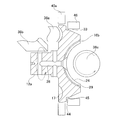
- FIG. 2 is a cross-sectional view of the trunnion and the outer ring constituting the power roller unit of the first example of the embodiment of the present invention.
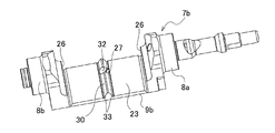
- FIG. 3 is a perspective view showing the trunnion constituting the power roller unit of the first example of the embodiment of the present invention as seen from the radially inner side of the input disk and the output disk.
- FIG. 4A is a partial cross-sectional view showing the shape of the protrusion formed on the trunnion side in the first example
- FIG. 4B is the shape of the concave groove formed on the outer ring side in the first example
- FIG. FIG. 5 is a partial cross-sectional view showing an engagement state between the protrusion shown in FIG. 4 (A) and the concave groove shown in FIG. 4 (B).
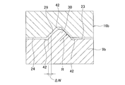
- FIG. 6 is a partial cross-sectional view for explaining the concept of the gap of the engaging portion between the protrusion and the groove in the first example.
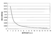
- FIG. 7 is a diagram showing the influence of the curvature radius of the cross-sectional shape of the side surface of the ridge on the wear of the engaging portion between the ridge and the groove in the first example.
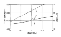
- FIG. 8 shows a situation in which the size of the gap between the protrusion and the groove in the first example leads to a sudden change in the gear ratio at the moment when the torque passing through the half-toroidal continuously variable transmission is reversed.
- FIGS. 9A and 9B are cross-sectional views showing two examples of a method of finishing the step surface formed on the outer peripheral edge of the outer ring of the outer ring of the first example.
- FIG. 10 is a cross-sectional view illustrating a state in which finishing is performed on the outer ring of the concave portion and the groove of the outer ring, the outer ring raceway, and the support shaft of the first example.
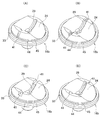
- FIG. 11A to 11D are perspective views showing four examples of positioning recesses provided on the outer surface of the outer ring of the first example.
- FIG. 12A and FIG. 12B are cross-sectional views for explaining the structure of the stopper for regulating the inclination angle of the power roller in the first example.
- FIG. 13 (A) is a cross-sectional view of the outer ring constituting the power roller unit of the second example of the embodiment of the present invention
- FIG. 13 (B) is a view of this outer ring from the lower side of FIG. 13 (A). It is a perspective view shown in the state.
- FIG. 14 is a perspective view for explaining a method of forming a recess, a groove, and a step surface on the outer surface of the outer ring of the second example.
- FIG. 15A is a perspective view showing a state in the middle of gripping the outer ring of the second example by the chuck
- FIG. 15B is a cross-sectional view showing a state where gripping of the outer ring by the chuck is completed.
- FIG. 16 is a perspective view for explaining a finishing process applied to the concave portion and the concave groove of the outer ring of the second example using an integrated grindstone.
- FIG. 17A is a perspective view for explaining the finishing process applied to the recess of the outer ring of the second example
- FIG. 10B shows the finishing process applied to the groove of the outer ring of the second example. It is a perspective view explaining.
- FIG. 16 is a perspective view for explaining a finishing process applied to the concave portion and the concave groove of the outer ring of the second example using an integrated grindstone.
- FIG. 17A is a perspective view for explaining the finishing process applied to the recess of the outer ring of the second example
- FIG. 10B shows the
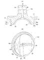
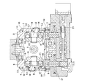
- FIG. 18 is a cross-sectional view showing a half-toroidal continuously variable transmission of a first example having a conventional structure.
- FIG. 19 is a cross-sectional view taken along the line aa in FIG.
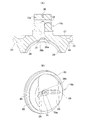
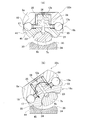
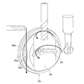
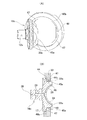
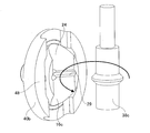
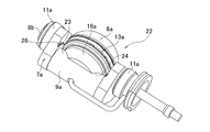
- FIG. 20 is a perspective view of the power roller unit constituting the half-toroidal continuously variable transmission of the second example of the conventional structure as seen from the radially outer side of the input disk and the output disk.
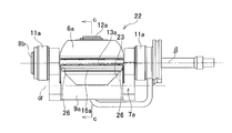
- FIG. 21 is a front view of a second example of a power roller unit having a conventional structure, as viewed from the circumferential direction of an input disk and an output disk.
- FIG. 22 is a plan view of the power roller unit of the second example of the conventional structure as viewed from above in FIG. FIG.
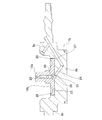
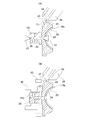
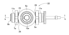
- FIG. 23 is a side view of the power roller unit of the second example having the conventional structure as viewed from the right side of FIG. 24 is a cross-sectional view taken along the line bb of FIG. 25 is a cross-sectional view taken along the line cc of FIG.
- FIG. 26 is a cross-sectional view seen from the same direction as FIG. 24, exaggeratingly showing a state in which the trunnion is elastically deformed based on the thrust load applied from the power roller in the second example of the conventional structure.
- the half-toroidal continuously variable transmission of this example basically includes at least one pair of disks (see FIG. 18) each composed of an input disk 2 and an output disk 5, a plurality of trunnions 7b, and trunnions 7b. And the same number of power rollers 6a (see FIG. 20) and the same number of thrust roller bearings 13a as thrust rolling bearings.
- the present invention relates to a structure of a power roller unit 22a including at least a trunnion 7b, a power roller 6a, and a thrust rolling bearing (thrust ball bearing) 13a among the half-toroidal continuously variable transmission, particularly the trunnion 7b and the thrust rolling bearing 13a. It is characterized in that the structure of the outer ring 16b that constitutes is devised.
- the power roller unit 22a further includes a radial rolling bearing (radial needle bearing) 25 that rotatably supports the power roller 6a around a support shaft 12a provided at the center of the inner surface of the outer ring 16b.
- the input disk 2 and the output disk 5 are supported concentrically with each other so that they can be rotated relative to each other in a state where the axial side surfaces of the toroidal curved surfaces each having an arc cross section are opposed to each other.
- the input disk 2 is supported by the input rotating shaft 1 and the output disk 5 is supported by the output cylinder 3 supported around the input rotating shaft 1 so as to be relatively rotatable.
- the output disk 5 can also be supported around the input rotary shaft 1 so as to be capable of direct relative rotation.
- the output disk 5 is integrated and disposed at the intermediate portion of the input rotary shaft 1, and both axial side surfaces thereof are opposed to one axial side surface of the input disk 2 disposed at both ends of the input rotary shaft 1.
- the trunnions 7 b are located between the axial side surfaces of the input disk 2 and the output disk 5, and are installed at a plurality of locations in the circumferential direction of the input disk 2 and the output disk 5.
- Each trunnion 7b exists between a pair of tilting shafts 8a and 8b provided concentrically with each other at both ends and the tilting shafts 8a and 8b, and at least the input disk 2 and the output disk 5
- the inner side surface in the radial direction is parallel to the central axis of the tilting shafts 8a and 8b, and the central axis existing outside the central direction of the tilting shafts 8a and 8b in the radial direction of the input disk 2 and the output disk 5
- a supporting beam portion 9b having a cylindrical convex surface 23.
- the tilt shafts 8a and 8b are connected by a support beam portion 9b.
- the tilting shafts 8a and 8b of the trunnion 7b are pivotally supported via a radial needle bearing 11 with respect to the support plate 10 so as to be twisted with respect to the central axes of the input disk 2 and the output disk 5 (see FIG. 18), the trunnion 7b is installed so as to be able to swing and swing around the tilting shaft 8.
- the power roller 6a is rotatably supported on the inner side surface of the trunnion 7b via a thrust ball bearing 13a, and the respective circumferential surfaces formed as spherical convex surfaces are respectively contacted with one side surface in the axial direction of the input disk 2 and the output disk 5. (See FIG. 18).
- the thrust ball bearing 13a is installed between the support beam portion 9b of the trunnion 7b and the outer surface of the power roller 6a.
- the thrust ball bearing 13a is provided on the support beam portion 9b side, and includes an outer ring 16b having an inner surface provided with an outer ring raceway 17 and an outer side provided with a recess 24, an outer ring raceway 17 of the outer ring 16b, and a power roller 6a.
- a plurality of balls 18 which are rolling elements are provided so as to be able to roll between the inner ring raceway 15 provided on the outer side surface.
- the outer ring 16b of the thrust rolling bearing 13a is manufactured by subjecting a metal material such as medium carbon steel or bearing steel to cutting or heat treatment.
- a power roller 6a is rotatably supported around a support shaft 12a integrally provided at the center of the inner surface of the outer ring 16b via a radial needle bearing 25 (see FIGS. 24 and 25) that is a radial rolling bearing. Is done.
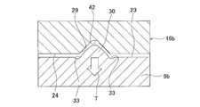
- the power roller 6a is related to the axial direction of the input disk 2 and the output disk 5 with respect to the trunnion 7b by engaging the concave portion 24 provided on the outer surface of the outer ring 16b with the cylindrical convex surface 23 of the support beam portion 9b. It is supported so as to be able to swing and displace (see FIG. 18). Further, on the inner surface of the recess 24 provided on the outer surface of the outer ring 16b, a concave groove 29 formed in the circumferential direction centering on the support beam portion 9b, and a ridge 30 formed on the outer peripheral surface of the support beam portion 9b. To limit the axial displacement of the support beam portion 9b.
- the concave groove 29 provided on the outer surface of the outer ring 16b is formed in a tapered shape with a wide opening and a narrow bottom.
- the cross-sectional shape of the inner surface on both sides of the groove 29 is a straight line as shown in FIGS. Note that an angle ⁇ (see FIG. 4B) formed by the extension line of the inner surface and the recess 24 is about 45 ° (40 ° to 50 °).
- the bottom of the concave groove 29 is formed as an extension line of inner side surfaces on both sides of the concave groove 29 and a relief concave portion 42 that is recessed from an arc surface that smoothly connects these inner side surfaces. Thus, the finishing of these inner surfaces is facilitated.
- the protrusion 30 formed on the outer peripheral surface of the support beam portion 9b is formed in a tapered shape with a wide base portion and a narrow tip portion.
- the outer side surfaces on both sides of the protrusion 30 are formed as partial arcs curved in a direction protruding toward the inner side surfaces on both sides of the concave groove 29 as shown in FIGS.
- the radius of curvature R of this partial arc is 2 mm or more.
- the portion of the outer peripheral surface of the support beam portion 9b that sandwiches the ridge 30 from both axial sides is a relief recess 42 that is recessed from the cylindrical convex surface 22 of the support beam portion 9b, and the outer surface of the ridge 30 is finished. Ease of processing is achieved.
- the outer surface of the ridge 30 and the cylindrical convex surface 22 are also processed at the same time as in the case of the concave portion 24 and the concave groove 29.
- the grinding process for finishing is performed by grinding the outer surface of the ridge 30 and the cylindrical convex surface 22 with an integrated grindstone. Thereby, the positional accuracy of the outer surface of the protrusion 30 and the cylindrical convex surface 22 is ensured.
- the outer surface of the protrusion 30 is formed regardless of the processing error between the outer surface of the protrusion 30 and the inner surface of the groove 29 by making the cross-sectional shape of the outer surface of the protrusion 30 a convex arc. It is possible to suppress wear of the rubbing portion between the groove 29 and the inner surface of the groove 29. That is, if the outer side surface of the ridge 30 and the inner side surface of the concave groove 29 are flat surfaces having a linear cross-sectional shape, the surface pressure of the contact portion between these surfaces can be kept low. However, due to processing errors and the like, it is difficult to make the outer surface of the ridge 30 and the inner surface of the concave groove 29 facing each other completely parallel.
- the cross-sectional shape of the outer surface of the protrusion 30 is a convex arc, but it is desirable to secure a curvature radius R of 2 mm or more of the partial arc that is the convex arc.
- Table 1 and FIG. 7 show the influence of the radius of curvature R of the partial arc on the wear amount of the rubbing portion between the outer side surface of the protrusion 30 and the inner side surface of the groove 29.
- the width dimension of the concave groove 29 is slightly larger than the width dimension of the protrusion 30.
- the size relationship between the width dimensions is such that the positions of the support beam portions 9b in the radial direction coincide with each other and the cylindrical convex surface 22 and the concave portion 24 are in contact with each other. This is the case when compared.
- the protrusion 30 does not bite into the concave groove 29 in a state where the cylindrical convex surface 22 and the concave portion 24 are in contact with each other, and the swing of the outer ring 16b with respect to the support beam portion 9b. Dynamic displacement is performed smoothly. Further, the power roller 6a (see FIG.
- the width of the groove 29 is larger than the width of the protrusion 30 by the portion indicated by ⁇ W in FIG. 6 at the portions where the positions of the support beam portions 9b in the radial direction coincide with each other.
- the amount that the outer ring 16b can be displaced in the axial direction of the support beam portion 9b with respect to the support beam portion 9b is limited to ⁇ W. .
- the extent to which the width of the concave groove 29 is made larger than the width of the ridge 30 ( ⁇ W) is as small as possible within a range in which the magnitude relation of the width dimension is not reversed regardless of manufacturing errors, specifically 0. It is necessary to suppress it to 0.050 mm or less. If the width difference ( ⁇ W) is suppressed to 0.050 mm or less, the amount of displacement of the power roller 6a in the axial direction of the trunnion 7b can be suppressed to a small extent regardless of the movement of the actuator 21 (see FIG. 19). Thereby, when the direction of torque transmission by the half-toroidal continuously variable transmission is reversed, it is possible to prevent the driver from feeling uncomfortable by performing an unintended shift operation.
- FIG. 8 shows a state in which a half-toroidal-type continuously variable transmission, a planetary gear mechanism, and a clutch device are combined, and a vehicle equipped with a continuously variable transmission that switches between a low speed mode and a high speed mode by this clutch device.
- the horizontal axis in FIG. 8 represents elapsed time
- the left vertical axis represents engine speed (rotational speed)
- the right vertical axis represents vehicle speed.
- the chain line ⁇ indicates the vehicle speed
- the solid line ⁇ indicates the engine speed when the width difference ( ⁇ W) between the concave groove 29 and the protrusion 30 is 0.125 mm
- the broken line ⁇ indicates the width difference ( ⁇ The engine speed when W) is 0.050 mm is shown.
- the clutch device is switched from the low speed mode state to the high speed mode state. As a result, the direction of torque transmission by the half-toroidal continuously variable transmission is reversed.
- the transmission ratio of the half toroidal continuously variable transmission can be reduced even when the torque transmission direction is reversed. Since it does not change regardless of the movement, the engine speed does not increase rapidly and does not give the driver a sense of incongruity.
- the support beam portion 9b installs the outer ring 16b. Elastically deforms into a circular arc with a concave side. As a result, as shown by an arrow T in FIG. 5, the protrusion 30 is displaced in the direction of coming out of the groove 29, and the gap between the outer surface of the protrusion 30 and the inner surface of the groove 29 tends to widen. . However, the actual spread amount is slight.
- the gap tends to widen, so that the power roller 6a does not transmit torque and the support beam portion 9b and the outer ring 16b are not elastically deformed. Even when ( ⁇ W) is suppressed to 0.050 mm or less, the ridge 30 is not sandwiched between the inner surfaces of the concave groove 29 when transmitting a large torque, and the support beam portion 9b is the center. The oscillating displacement of the outer ring 16b is smoothly performed. Also, when the torque transmitted by the half-toroidal continuously variable transmission is large, even if the engine speed fluctuates due to a slight change in the gear ratio, the driver feels a little strange compared to when the torque is low. It does n’t matter.
- a circular central recess 31 having an opening diameter larger than the width dimension of the groove 29 is formed in the circumferential center of the groove 29, which is aligned with the upstream end opening of the downstream lubricating oil passage 28.
- a notch 32 is formed at the center in the circumferential direction of the ridge 30 that is aligned with the downstream end opening of the upstream lubricating oil passage 27.
- the lubricating oil supply to the thrust ball bearing 13a and the radial needle bearing 25 through the upstream lubricating oil flow path 27 and the downstream lubricating oil path 28 is caused by the oscillation displacement of the outer ring 16b around the support beam portion 9b. Regardless of, it can be performed stably.
- the difference in width ( ⁇ W) between the concave groove 29 and the protrusion 30 is suppressed to 0.050 mm or less.
- the concentricity between the concave portion 24 provided on the outer surface of the outer ring 16b and the concave groove 29 formed on the inner surface of the concave portion 24 is 0.015 mm or less, preferably 0.010 mm or less, more preferably 0. It is necessary to regulate to 0.005 mm or less.
- the recess 24 and the groove 29 are finished by grinding with an integrated grindstone.
- the general-purpose grindstone since the general-purpose grindstone has a large contact area and a large rotational resistance, its use may reduce the efficiency of the finishing process and increase the manufacturing cost.
- the concave portion 24 and the concave groove 29 by simultaneously grinding with a separate grindstone with one chuck.
- the outer ring 16b in order to ensure the coaxiality between the concave portion 24 and the concave groove 29, the outer ring 16b needs to be chucked with high accuracy when finishing the concave portion 24 and the concave groove 29. .
- the trunnions 7b installed in different cavities are synchronized with each other by the same angle in the reverse direction (the same direction with respect to the direction of change in the gear ratio).
- the installation position of the power roller 6a is regulated with high accuracy. For this reason, it is necessary to regulate the size and shape of each part of the power roller unit 22a with high accuracy, particularly between the power roller units 22a incorporated in the same half-toroidal continuously variable transmission.
- a stepped portion 33 is provided over the entire circumference on the outer peripheral edge of the outer surface of the outer ring 16b as a reference surface when finishing the outer ring 16b.
- the concave portion 24 and the concave groove 29 are simultaneously formed on the outer surface of the outer ring 16b by cutting, and after heat treatment, the outer peripheral edge of the outer surface of the outer ring 16b is cut over the entire circumference to form the step portion 33.
- a finishing process such as grinding or hard turning is performed on the radial step surface 44 and the axial step surface 45 constituting the step portion 33 and the outer peripheral surface of the outer ring 16b.
- the radial step surface 44 and the axial step surface 45 of the step portion 33 and the outer peripheral surface of the outer ring 16b are finished, and the radial step surface of the support shaft 12a with respect to the rotation center axis. 44 and the parallelism of the axial step surface 45 and the outer peripheral surface of the outer ring 16b with respect to the rotation center axis of the support shaft 12a are improved.
- two-step chamfered portions 39a and 39b are provided on the inner peripheral edge of the opening portion of the downstream lubricating oil passage 28. Provided. However, if the roundness of the finishing process of the stepped portion 33 can be ensured, a single chamfered portion can be used.
- the inner surface of the outer ring 16b (the left side surface of FIG. 9B) is suppressed by the backup jig 43, and the outer peripheral surface of the support shaft 12a is gripped by the chuck 40.
- the outer ring 16b can be rotated, and the stepped portion 33 and the outer peripheral surface of the outer ring 16b can be finished.
- the axial end surface of the positioning jig 46 is abutted against the radial stepped surface 44, and the axial direction of the support shaft 12 a is related.
- the outer circumferential surface of the outer ring 16b is gripped by the chuck 40a, whereby positioning (centering) in the radial direction of the outer ring 16b can be achieved.
- positioning recesses for positioning the chuck 40a in the circumferential direction at two positions spaced in the radial direction of the outer surface of the outer ring 16b. 41 is provided.
- Such a positioning recess 41 only needs to be able to position the chuck 40a in the circumferential direction, and various structures shown in FIGS. 11A to 11D can be arbitrarily employed.
- a long groove in the axial direction of the support shaft 12a is provided in the inner peripheral edge of the stepped portion 33 at two positions on the opposite side in the radial direction while being recessed radially inward.
- the concave groove 29 is formed across the width direction of the outer ring 16b, that is, in the state where the outer ring 16b is open at both end edges in the width direction, and both end portions in the width direction of the concave groove 29 are positioned.
- a recess 41 is provided.
- a concave groove different from the concave groove 29 is formed in the width direction at two positions in the width direction on the outer surface of the outer ring 16b to form the positioning concave portion 41.
- pin holes are provided at two positions in the width direction on the outer surface of the outer ring 16b to form positioning recesses 41.
- the convex portion provided on the chuck 40a side is engaged with the positioning concave portion 41 of the outer ring 16b, thereby positioning the chuck 40a in the circumferential direction of the outer ring 16b.
- the outer ring 16b is rotated by rotating the chuck 40a with the outer peripheral surface of the outer ring 16b gripped by the chuck 40a, and the outer ring raceway 17 is rotated by the grindstone 38a.
- the outer peripheral surface of 12a with the grindstone 38b By grinding the outer peripheral surface of 12a with the grindstone 38b, the outer ring raceway 17 and the outer peripheral surface of the support shaft 12a can be finished.
- the concave portion 24 and the concave groove 29 are ground by the integrated grindstone 38c so that the concave portion 24 and the concave groove 29 can be finished.
- the shifting operation of the half toroidal continuously variable transmission can be more reliably stabilized. That is, in this example, with the radial stepped surface 44 and the axial stepped surface 45 of the stepped portion 33 formed on the outer peripheral edge of the outer ring 16b as the reference plane, the recessed portion 24 and the recessed groove 29, the outer ring raceway 17, and The outer peripheral surface of the support shaft 12a can be simultaneously finished with a single chuck.
- the concentricity between the concave portion 24 and the concave groove 29 can be improved to 0.015 mm or less, preferably 0.010 mm or less, more preferably 0.005 mm or less, and the outer ring 16b supports the trunnion 7b.
- the amount ( ⁇ W) that can be displaced in the axial direction of the support beam portion 9b with respect to the beam portion 9b can be suppressed to 0.050 mm or less.
- the parallelism between the recess 24 and the outer ring raceway 17, the perpendicularity between the recess 24 and the support shaft 12a, and the error in the assembly height of the power roller 6a with respect to the trunnion 7b are also 0.015 mm or less, preferably 0. 0.010 mm or less, more preferably 0.005 mm or less.
- the half-toroidal continuously variable transmission of the present example includes a synthetic resin stopper 34 having a contact surface 35.
- the stopper 34 is configured so that the trunnion 7b is tilted in a pair in a state where the power roller unit 22a is assembled in a fixed part (see FIG. 19) such as a casing of the half toroidal continuously variable transmission in the half toroidal continuously variable transmission.
- the inclination angle of the trunnion 7b is limited to a certain range.
- the shape of the stopper 34 including the contact surface 35 is arbitrary as long as the contact surface 35 can receive the stepped portion 33 when the trunnion 7b is swung to the allowable limit. is there.
- members existing between the rolling contact portion (traction portion) between the power roller 6a and the inner surfaces of the input disk 2 and the output disk 5 and the stopper 34 are the power roller 6a, the ball of the thrust ball bearing 13a, and The outer ring 16b alone is smaller than the structure described in Japanese Utility Model Laid-Open No. 6-43404, and the distance therebetween is also short. Therefore, the inclination angle of the power roller 6a with respect to the input disk 2 and the output disk 5 can be regulated more accurately.
- other configurations and operations including the overall structure of the half-toroidal continuously variable transmission are the same as the conventional structure.
- FIG. 13 to 17 show a second example of the embodiment of the present invention.
- the outer peripheral surface of the outer ring 16c in addition to the stepped portion 33 provided on the outer peripheral surface of the outer ring 16c over the entire periphery, the outer peripheral surface of the outer ring 16c A pair of left and right step portions 33a parallel to the axial direction of the support beam portion 9b (see FIGS. 2, 3, and 12) of the trunnion 7b engaged with the recess 24 is provided on both sides in the width direction across the recess 24. Is provided. As shown in FIG.
- the stepped portion 33 a is formed by cutting (milling) at the same time as forming the concave portion 24 and the concave groove 29 with one chuck. After that, heat treatment is performed on the outer ring 16c. Further, the end surface of the circumferential protrusion 47 provided on the chuck 40b is abutted against the radial step surface 44 of the step portion 33, thereby positioning the support shaft 12a in the axial direction with the beam portion 48 also received by the chuck 40b. By engaging the axial step surface 45a of the step portion 33a with the positioning in the circumferential direction of the outer ring 16c, the outer ring 16c faces the chuck 40b and is pressed to the right in FIG. 15B. .
- the outer ring 16c is gripped by the chuck 40b, thereby positioning (centering) the outer ring 16c in the radial direction.
- the chuck 40b is rotated, and the outer ring raceway 17 of the outer ring 16c and the outer peripheral surface of the support shaft 12a are ground with a grindstone.
- the concave portion 24 and the concave groove 29 are ground by the integral type grindstone 38c as shown in FIG. 16 without replacing the chuck 40b.
- FIG. 17A after the concave portion 24 is ground over the axial direction of the support beam portion 9b by the grindstone 38d, the concave groove 29 is surrounded by the grindstone 38e as shown in FIG. 17B. Grind over direction.
- the stepped portion 33a is provided on both sides of the outer circumferential surface of the outer ring 16c in the width direction across the concave portion 24. Therefore, unlike the first example of the embodiment, it is not necessary to provide the positioning recess 41 (see FIG. 11) for positioning the chuck in the circumferential direction on the outer surface of the outer ring 16c. Further, the stepped portion 33a is provided in parallel with the central axis of the concave portion 24 having a partial cylindrical surface shape, and the positioning of the stepped portion 33a and the beam portion 48 in the circumferential direction of the outer ring 16c of the chuck 40b is achieved. .
- the step surface 44a may be a surface that contacts the contact surface 35 of the stopper 34 (see FIG. 12).
- Other configurations and operations are the same as in the first example of the embodiment.
- the present invention is not only for automatic transmissions for vehicles, but also for automatic transmissions for construction machinery, automatic transmissions for generators used in aircraft, etc., for adjusting the operating speed of various industrial machines such as pumps.
- the present invention can be widely applied to a half toroidal continuously variable transmission used as an automatic transmission.
Abstract
La présente invention a trait à une unité de rouleau de puissance (22a) dont les composants sont faciles à fabriquer et à gérer, qui est facile à assembler et au moyen de laquelle le fonctionnement d'une transmission à variation continue semi-toroïdale est stabilisé. Un tourillon (7b) est équipé d'arbres de rotation inclinés (8a, 8b) et d'une poutre de support (9b) dont la surface intérieure est une surface convexe cylindrique (23). Un anneau extérieur (16b), qui forme une butée (13a) qui supporte de façon rotative un rouleau de puissance (6a) dans la poutre de support (9b), est équipé d'une partie concave (24) qui s'engrène avec la surface convexe cylindrique (23), et est équipé d'un chemin de roulement d'anneau extérieur (17) et d'un arbre-support (12a). Le déplacement de la poutre de support (9b) dans la direction axiale est restreint par l'engagement d'une protubérance conique (30) qui est prévue sur la surface intérieure de la poutre de support (9b) et d'une rainure concave conique (29) qui est prévue dans la partie concave (24) de l'anneau extérieur (16b). De plus, une partie à étages (33), qui tient lieu de surface de référence lorsqu'un processus de finition est effectué sur les surfaces circonférentielles extérieures de la partie concave (24), de la rainure concave (29), du chemin de roulement d'anneau extérieur (17) et de l'arbre-support (12a), est prévue sur une portion du bord circonférentiel extérieur sur la surface extérieure de l'anneau extérieur (16b).
Priority Applications (1)
| Application Number | Priority Date | Filing Date | Title |
|---|---|---|---|
| CN201380002551.5A CN103732948B (zh) | 2012-06-13 | 2013-06-13 | 动力滚子单元、其制造方法和半环形无级变速器 |
Applications Claiming Priority (2)
| Application Number | Priority Date | Filing Date | Title |
|---|---|---|---|
| JP2012-133453 | 2012-06-13 | ||
| JP2012133453A JP5953961B2 (ja) | 2012-06-13 | 2012-06-13 | トロイダル型無段変速機及びその製造方法 |
Publications (1)
| Publication Number | Publication Date |
|---|---|
| WO2013187488A1 true WO2013187488A1 (fr) | 2013-12-19 |
Family
ID=49758306
Family Applications (1)
| Application Number | Title | Priority Date | Filing Date |
|---|---|---|---|
| PCT/JP2013/066387 WO2013187488A1 (fr) | 2012-06-13 | 2013-06-13 | Unité de rouleau de puissance, son procédé de fabrication et transmission à variation continue semi-toroïdale |
Country Status (3)
| Country | Link |
|---|---|
| JP (1) | JP5953961B2 (fr) |
| CN (1) | CN103732948B (fr) |
| WO (1) | WO2013187488A1 (fr) |
Cited By (1)
| Publication number | Priority date | Publication date | Assignee | Title |
|---|---|---|---|---|
| EP2811204A4 (fr) * | 2012-02-03 | 2016-08-24 | Nsk Ltd | Transmission à variation continue de type toroïdal |
Citations (4)
| Publication number | Priority date | Publication date | Assignee | Title |
|---|---|---|---|---|
| JP2001090795A (ja) * | 1999-09-27 | 2001-04-03 | Nissan Motor Co Ltd | トロイダル型無段変速機 |
| JP2003148576A (ja) * | 2001-11-14 | 2003-05-21 | Koyo Seiko Co Ltd | バリエータ用ディスクの製造方法 |
| JP2008025821A (ja) * | 2006-06-02 | 2008-02-07 | Nsk Ltd | トロイダル型無段変速機 |
| JP2011174539A (ja) * | 2010-02-24 | 2011-09-08 | Nsk Ltd | トロイダル無断変速機 |
Family Cites Families (3)
| Publication number | Priority date | Publication date | Assignee | Title |
|---|---|---|---|---|
| JP3711688B2 (ja) * | 1997-03-22 | 2005-11-02 | マツダ株式会社 | トロイダル式無段変速機 |
| JP5077834B2 (ja) * | 2009-12-15 | 2012-11-21 | 日本精工株式会社 | トロイダル型無段変速機 |
| US8876654B2 (en) * | 2009-11-25 | 2014-11-04 | Nsk Ltd. | Toroidal continuously variable transmission |
-
2012
- 2012-06-13 JP JP2012133453A patent/JP5953961B2/ja active Active
-
2013
- 2013-06-13 CN CN201380002551.5A patent/CN103732948B/zh not_active Expired - Fee Related
- 2013-06-13 WO PCT/JP2013/066387 patent/WO2013187488A1/fr active Application Filing
Patent Citations (4)
| Publication number | Priority date | Publication date | Assignee | Title |
|---|---|---|---|---|
| JP2001090795A (ja) * | 1999-09-27 | 2001-04-03 | Nissan Motor Co Ltd | トロイダル型無段変速機 |
| JP2003148576A (ja) * | 2001-11-14 | 2003-05-21 | Koyo Seiko Co Ltd | バリエータ用ディスクの製造方法 |
| JP2008025821A (ja) * | 2006-06-02 | 2008-02-07 | Nsk Ltd | トロイダル型無段変速機 |
| JP2011174539A (ja) * | 2010-02-24 | 2011-09-08 | Nsk Ltd | トロイダル無断変速機 |
Cited By (1)
| Publication number | Priority date | Publication date | Assignee | Title |
|---|---|---|---|---|
| EP2811204A4 (fr) * | 2012-02-03 | 2016-08-24 | Nsk Ltd | Transmission à variation continue de type toroïdal |
Also Published As
| Publication number | Publication date |
|---|---|
| JP2013256996A (ja) | 2013-12-26 |
| CN103732948B (zh) | 2016-06-29 |
| JP5953961B2 (ja) | 2016-07-20 |
| CN103732948A (zh) | 2014-04-16 |
Similar Documents
| Publication | Publication Date | Title |
|---|---|---|
| JP6117991B2 (ja) | トロイダル無段変速機 | |
| JP5077834B2 (ja) | トロイダル型無段変速機 | |
| JP5835361B2 (ja) | トロイダル型無段変速機 | |
| JP3932027B2 (ja) | トロイダル型無段変速機 | |
| WO2013187488A1 (fr) | Unité de rouleau de puissance, son procédé de fabrication et transmission à variation continue semi-toroïdale | |
| JP5747723B2 (ja) | トロイダル型無段変速機のトラニオンおよびその加工方法 | |
| JP4962350B2 (ja) | トロイダル型無段変速機 | |
| JP2008275088A (ja) | トロイダル型無段変速機 | |
| JP2006308037A (ja) | トロイダル型無段変速機 | |
| JP5939015B2 (ja) | トロイダル型無段変速機 | |
| JP5803584B2 (ja) | トロイダル型無段変速機およびその部品の加工方法 | |
| JP5895463B2 (ja) | トロイダル型無段変速機 | |
| JP5803378B2 (ja) | トロイダル型無段変速機 | |
| JP5830999B2 (ja) | トロイダル型無段変速機 | |
| JP5673205B2 (ja) | トロイダル型無段変速機 | |
| JP6458443B2 (ja) | トロイダル型無段変速機 | |
| JP4702602B2 (ja) | トロイダル型無段変速機 | |
| JP4915287B2 (ja) | トロイダル型無段変速機 | |
| JP4106868B2 (ja) | トロイダル型無段変速機及びトラニオンの孔加工方法 | |
| JP5082498B2 (ja) | トロイダル型無段変速機 | |
| JP2020069567A (ja) | 主軸装置および工作機械 | |
| JP2012112483A (ja) | トロイダル型無段変速機 | |
| JP2012117569A (ja) | トロイダル型無段変速機 | |
| JP2015047670A (ja) | トロイダル型無段変速機用ディスクの製造方法 | |
| JP2012225451A (ja) | トロイダル型無段変速機 |
Legal Events
| Date | Code | Title | Description |
|---|---|---|---|
| 121 | Ep: the epo has been informed by wipo that ep was designated in this application |
Ref document number: 13804646 Country of ref document: EP Kind code of ref document: A1 |
|
| NENP | Non-entry into the national phase |
Ref country code: DE |
|
| 122 | Ep: pct application non-entry in european phase |
Ref document number: 13804646 Country of ref document: EP Kind code of ref document: A1 |