WO2013187488A1 - Power roller unit, manufacturing method therefor, and half-toroidal continuously variable transmission - Google Patents
Power roller unit, manufacturing method therefor, and half-toroidal continuously variable transmission Download PDFInfo
- Publication number
- WO2013187488A1 WO2013187488A1 PCT/JP2013/066387 JP2013066387W WO2013187488A1 WO 2013187488 A1 WO2013187488 A1 WO 2013187488A1 JP 2013066387 W JP2013066387 W JP 2013066387W WO 2013187488 A1 WO2013187488 A1 WO 2013187488A1
- Authority
- WO
- WIPO (PCT)
- Prior art keywords
- outer ring
- power roller
- support beam
- trunnion
- pair
- Prior art date
Links
Images


Classifications
-
- F—MECHANICAL ENGINEERING; LIGHTING; HEATING; WEAPONS; BLASTING
- F16—ENGINEERING ELEMENTS AND UNITS; GENERAL MEASURES FOR PRODUCING AND MAINTAINING EFFECTIVE FUNCTIONING OF MACHINES OR INSTALLATIONS; THERMAL INSULATION IN GENERAL
- F16H—GEARING
- F16H15/00—Gearings for conveying rotary motion with variable gear ratio, or for reversing rotary motion, by friction between rotary members
- F16H15/02—Gearings for conveying rotary motion with variable gear ratio, or for reversing rotary motion, by friction between rotary members without members having orbital motion
- F16H15/04—Gearings providing a continuous range of gear ratios
- F16H15/06—Gearings providing a continuous range of gear ratios in which a member A of uniform effective diameter mounted on a shaft may co-operate with different parts of a member B
- F16H15/32—Gearings providing a continuous range of gear ratios in which a member A of uniform effective diameter mounted on a shaft may co-operate with different parts of a member B in which the member B has a curved friction surface formed as a surface of a body of revolution generated by a curve which is neither a circular arc centered on its axis of revolution nor a straight line
- F16H15/36—Gearings providing a continuous range of gear ratios in which a member A of uniform effective diameter mounted on a shaft may co-operate with different parts of a member B in which the member B has a curved friction surface formed as a surface of a body of revolution generated by a curve which is neither a circular arc centered on its axis of revolution nor a straight line with concave friction surface, e.g. a hollow toroid surface
- F16H15/38—Gearings providing a continuous range of gear ratios in which a member A of uniform effective diameter mounted on a shaft may co-operate with different parts of a member B in which the member B has a curved friction surface formed as a surface of a body of revolution generated by a curve which is neither a circular arc centered on its axis of revolution nor a straight line with concave friction surface, e.g. a hollow toroid surface with two members B having hollow toroid surfaces opposite to each other, the member or members A being adjustably mounted between the surfaces
Definitions
- the present invention relates to a half-toroidal continuously variable transmission, particularly a trunnion that is swingably supported by the half-toroidal continuously variable transmission, and a half-toroidal continuously variable transmission that is used as a transmission for a vehicle such as an automobile.
- the present invention relates to a power roller unit including at least an outer ring that constitutes a thrust rolling bearing for rotatably supporting a power roller that is sandwiched between an input disk and an output disk and that transmits torque with respect to a trunnion.
- CVT continuously variable continuously variable transmission
- a half-toroidal continuously variable transmission that realizes a continuously variable transmission by changing the inclination angle of a power roller sandwiched between an input disk and an output disk.
- a half-toroidal continuously variable transmission, a planetary gear mechanism, and a clutch device are combined to increase the adjustment range of the transmission ratio of the entire transmission (see JP 2004-169719 A).
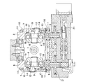
- FIGS. 18 and 19 show a first example of a conventional half-toroidal continuously variable transmission.
- a pair of input disks 2 are supported around a portion near both ends of the input rotation shaft 1 so as to be able to rotate in synchronization with the input rotation shaft 1.
- An output cylinder 3 is supported around the intermediate portion of the input rotation shaft 1 so as to be rotatable with respect to the input rotation shaft 1.
- An output gear 4 is fixed at the axial center of the outer peripheral surface of the output cylinder 3, and a pair of output disks 5 are rotated in synchronization with the output cylinder 3 by spline engagement at both axial ends. Is supported by possible.
- each combination of the input disk 2 and the output disk 5 the inner surface of the input disk 2 and the inner surface of the output disk 5 are opposed to each other, each of which is a toroidal curved surface.
- a plurality of power rollers 6 each having a spherical convex surface are sandwiched between the input disk 2 and the output disk 5.
- Each of these power rollers 6 is rotatably supported by the trunnion 7.
- Each trunnion 7 includes a pair of tilting shafts 8 provided concentrically with each other at both ends in the axial direction, and support beam portions 9 that connect these tilting shafts 8.
- the tilting shaft 8 of the trunnion 7 is pivotally supported via a radial needle bearing 11 with respect to the support plate 10 so as to be in a twisted position with respect to the center axis of the input disc 2 and the output disc 5.
- the rocking displacement is possible around the tilting axis 8.
- Each power roller 6 includes a support shaft 12 in which the base half and the front half are eccentric from each other on the inner side surface of the support beam portion 9 of the trunnion 7, and between the support beam portion 9 and the outer surface of the power roller 6.
- the thrust ball bearing 13 and the thrust needle bearing 14 provided in order from the power roller 6 side, the rotation about the front half of the support shaft 12 and the base half of the support shaft 12 are centered. It is supported so that a slight swing displacement is possible.
- the thrust ball bearing 13 supports the rotation of the power roller 6 while supporting a load in the thrust direction applied to the power roller 6, and the inner ring raceway 15 formed on the outer surface of the power roller 6 and the inner ring 16
- the outer ring raceway 17 is formed on the side surface, and a plurality of balls 18 are provided between these raceways so as to be able to roll.
- the thrust needle bearing 14 supports the thrust load applied to the outer ring 16 of the thrust ball bearing 13 from the power roller 6, and the front half of the outer ring 16 and the support shaft 12 is centered on the base half of the support shaft 12. It is allowed to swing.
- the power roller unit, the trunnion 7, the thrust ball bearing 13, and the thrust needle bearing 14 constitute a power roller unit.
- one input disk 2 (left side in FIG. 18) is rotationally driven by the drive shaft 19 via the pressing device 20.
- the pair of input disks 2 supported at both ends of the input rotating shaft 1 rotate synchronously while being pressed toward each other.
- This rotation is transmitted to the output disk 5 through the power roller 6 and is taken out from the output gear 4.
- the trunnion 7 is displaced in the axial direction of the tilt shaft 8 by the hydraulic actuator 21.
- the input disk 2, the output disk 5, and the power roller 6 that are used for power transmission are elastically deformed based on the pressing force generated by the pressing device 20. And with this elastic deformation, the input disk 2 and the output disk 5 are displaced in the axial direction. Further, the pressing force generated by the pressing device 20 increases as the torque transmitted by the half-toroidal continuously variable transmission increases, and the elastic deformation amount of the input disk 2, the output disk 5, and the power roller 6 increases accordingly. . Therefore, in order to maintain the contact state between the inner surface of the input disk and the output disk 5 and the peripheral surface of the power roller 6 regardless of torque fluctuation, the power roller 6 is connected to the trunnion 7 with respect to the input disk 2.
- a mechanism for displacing the output disk 5 in the axial direction is required.
- the front half of the support shaft 12 that supports the power roller 6 is oscillated and displaced about the base half thereof, so that the power roller 6 is moved to the shafts of the input disk 2 and the output disk 5. It is displaced in the direction.
- such a structure is complicated, and the production of the parts of the power roller unit, the parts management, and the assembly work are all complicated, and the manufacturing cost of the half-toroidal continuously variable transmission increases.
- Japanese Patent Laid-Open No. 2008-25821 discloses a second example of a conventional structure in which the structure for displacing the power roller in the axial direction of the input disk and the output disk is improved in order to solve such a problem.
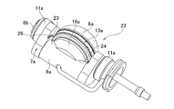
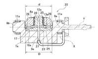
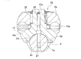
- the trunnion 7a constituting the second example of the conventional structure includes a pair of tilting shafts 8a and 8b concentrically provided at both ends, and these tilting shafts 8a, 8b, and a cylindrical convex surface 23 on the inner side (upper side in FIGS. 24 and 25) in the radial direction (the vertical direction in FIGS. 24 and 25) of at least the input disk 2 and the output disk 5 And a beam portion 9a.
- the tilting shafts 8a and 8b are supported on the support plate 10 (see FIG. 19) via a radial needle bearing 11a, respectively, so as to be swingable and axially displaceable.
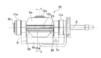
- the center axis X of the cylindrical convex surface 23 is parallel to the center axis Y of the tilt axes 8a and 8b, and is more than the center axis Y of these tilt axes 8a and 8b.
- a concave portion 24 having a partially cylindrical surface is formed on the outer surface of the outer ring 16a constituting the thrust ball bearing 13a provided between the support beam portion 9a and the outer surface of the power roller 6a so as to cross the outer surface in the radial direction. Is provided.
- the outer ring 16a supports the trunnion 7a so as to be able to swing and displace in the axial direction of the input disk 2 and the output disk 5. Is done.
- the support shaft 12a is provided integrally with the outer ring 16a at the center of the inner surface of the outer ring 16a, and the power roller 6a is rotatably supported around the support shaft 12a via a radial needle bearing 25.
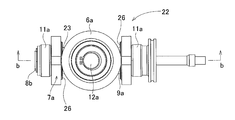
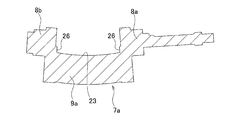
- a pair of stepped surfaces 26 facing each other are provided on the inner surface of the trunnion 7a at a continuous portion between both ends of the support beam portion 9a and the pair of tilting shafts 8a and 8b.
- These step surfaces 26 and the outer peripheral surface of the outer ring 16a of the thrust ball bearing 13a are brought into contact with or in close proximity to each other, and the traction force applied from the power roller 6a to the outer ring 16a is at any step surface 26. It comes to be supported.
- the power roller unit 22 is configured by the power roller 6a, the trunnion 7a, the thrust ball bearing 13a, and the radial needle bearing 25.
- the power roller 6a is displaced in the axial direction of the input disk 2 and the output disk 5, regardless of changes in the amount of elastic deformation of these constituent members.
- a structure capable of appropriately maintaining the contact state between the peripheral surface of the power roller 6a and the input disk 2 and the output disk 5 is realized simply and at low cost. That is, when the half-toroidal continuously variable transmission is operated, it is necessary to displace the power roller 6a in the axial direction of the input disk 2 and the output disk 5 based on elastic deformation of the input disk 2, the output disk 5, and the power roller 6a.
- the outer ring 16a of the thrust ball bearing 13a that rotatably supports the power roller 6a slides on the contact surface between the concave portion 24 of the partial cylindrical surface provided on the outer surface and the cylindrical convex surface 23 of the support beam portion 9a. In this manner, the cylindrical convex surface 23 is oscillated and displaced about the central axis X. Based on this oscillating displacement, a portion of the peripheral surface of the power roller 6a that is in rolling contact with one axial side surface of the input disk 2 and the output disk 5 is displaced in the axial direction of the input disk 2 and the output disk 5. The contact state between these components is properly maintained.
- the center axis X of the cylindrical convex surface 23 exists outside the center axis Y of the tilting shafts 8a and 8b, which are the center of oscillation of the trunnion 7a during the speed change operation, in the radial direction of the input disk 2 and the output disk 5. To do. Accordingly, since the radius of the rocking displacement around the central axis X of the cylindrical convex surface 23 is larger than the rocking radius at the time of the shifting operation, the power roller 6a having the central axis X of the cylindrical convex surface 23 as the center. The influence of the rocking displacement on the fluctuation of the transmission ratio between the input disk 2 and the output disk 5 is negligible or can be easily corrected.
- the distance D between the step surfaces 26 provided in pairs at both ends of the support beam portion 9a in order to smoothly swing and displace the outer ring 16a around the support beam portion 9a. Is slightly larger than the outer diameter d of the outer ring 16a (D> d). Therefore, the outer ring 16a and the power roller 6a can be displaced in the axial direction of the support beam portion 9a by the difference (D ⁇ d) between the distance D and the outer diameter d.
- the shift operation that is started for such a cause is a shift operation that is not directly related to the driving operation, and even if it is corrected anyway, the driver feels uncomfortable.
- the torque transmitted by the half-toroidal continuously variable transmission is low, the occurrence of such a shifting operation not intended by the driver may give the driver a great sense of incongruity.
- the force “2 Ft” is supported by engaging the protrusions formed on the outer peripheral surface of the support beam portion and having axially opposite sides parallel to each other and the groove formed on the inner surface of the recess on the outer ring side.
- the structure to be described is also described.
- the both sides of the ridge are polished on both sides of the ridge at the time of polishing to finish with high accuracy. Damage due to burning is likely to occur. That is, this polishing process is performed by pressing the rotated grindstone against both side surfaces of the ridge.
- both sides of the ridge which is the processed surface
- both sides of the ridge are parallel to each other, in other words, because both sides of the ridge are perpendicular to the rotation axis of the grindstone, the temperature of both sides of the ridge rises and polishing burns occur. It tends to occur.
- the axial direction of the rotating shaft of this grindstone and the pressing direction are parallel, it is impossible to polish both sides of the ridge and the cylindrical convex surface at the same time. It is the cause that raises.
- the peripheral surface of the power roller protrudes radially outward of the inner surface of the input disk and output disk, or the outer peripheral edge of the outer ring and the thrust ball. It is necessary to prevent the outer peripheral edge of the cage that holds the balls constituting the bearing from coming into contact with the inner surfaces of the input disk and the output disk.
- the tip of the support plate provided at the end of the trunnion has an inclined edge, and the inclined edge and a stopper fixed to the housing or the like are swung to the allowable limit.
- the members existing between the rolling contact portion between the peripheral surface of the power roller and the inner surface of the input disk and the output disk and the contact portion between the inclined edge and the stopper are the power roller, thrust It consists of balls, outer rings, and trunnions constituting a ball bearing, and has a large number of members and a long distance between them. Therefore, there is room for improvement in terms of regulating the inclination angle of the power roller with respect to the input disk and the output disk with higher accuracy.
- the present invention makes it easy to manufacture parts, manage parts, and assemble, facilitate cost reduction, stabilize the speed change operation, and further, if necessary, the inclination angle of the power roller with respect to the input disk and output disk It is an object of the present invention to provide a power roller unit capable of regulating the above and a half toroidal continuously variable transmission including the power roller unit.
- a half toroidal continuously variable transmission includes at least a pair of disks, a plurality of power rollers, and a power roller unit having at least the same number of the power rollers and at least an outer ring constituting a trunnion and a thrust rolling bearing.
- the pair of discs are supported concentrically with each other so that they can rotate relative to each other in a state in which one side surface of each axial direction is a toroidal curved surface having an arc cross section.
- the pair of disks includes an input disk supported around the input rotation shaft of the half toroidal continuously variable transmission so as to be able to rotate in synchronization with the input rotation shaft, and around the input rotation shaft. And an output disk supported so as to be relatively rotatable.
- a pair of input disks are arranged near both ends of the input rotation shaft, and a pair of output disks or an integrated output disk is arranged in the middle of the input rotation shaft. Is placed.
- the trunnion constituting the power roller unit includes a pair of tilting shafts concentrically provided at both ends, and a support beam portion provided between the tilting shafts and connecting these tilting shafts.
- the support beam portion is assembled in a half toroidal continuously variable transmission, and is parallel to the central axis of the tilting shaft on the inner side in the radial direction of a pair of disks constituting the half toroidal continuously variable transmission.
- An inner side surface comprising a cylindrical convex surface having a central axis that exists outside the central axis of the tilt axis in the radial direction of the pair of disks is provided.
- the thrust rolling bearing constituting the power roller unit supports the power roller having a peripheral surface made of a spherical convex surface that abuts one axial side surface made of a toroidal curved surface having a circular arc cross section of each of the pair of disks. It supports so that it can rotate with respect to the inner surface of a beam part.
- the outer ring constituting the thrust rolling bearing includes an outer surface provided with a recess that engages with an inner side surface of the support beam portion, an inner side surface provided with an outer ring raceway of the thrust rolling bearing, and a central portion of the inner side surface And a support shaft that rotatably supports the power roller.
- the power roller unit refers to a structure including at least a trunnion and an outer ring constituting a thrust rolling bearing.
- the power roller unit includes a plurality of rolling elements provided so as to roll between an inner ring raceway provided on an outer surface of the power roller and an outer ring raceway of the outer ring, and the power roller including the power roller.
- a radical rolling bearing that is rotatably supported around the support shaft is also included.
- the combination of the power roller unit and the power roller of the present invention is also referred to as a power roller unit.
- a tapered protrusion extending in the circumferential direction of the cylindrical convex surface on the inner surface of the support beam portion of the trunnion and having a wide base and a narrow tip.
- a tapered groove Formed in the recess on the outer surface of the outer ring, and is formed with a tapered groove extending in the circumferential direction of the recess and having a wide opening and a narrow bottom. The axial displacement of the support beam portion is limited by the engagement of the concave groove.
- At least part of the outer peripheral edge portion of the outer surface of the outer ring, with the outer ring held by a chuck, the recess and the groove, the outer ring raceway, and the outer peripheral surface of the support shaft are ground or A step portion is provided as a reference surface when finishing such as hard turning finish.
- the stepped portion is provided in the axial direction of the support beam portion on both sides in the width direction sandwiching the concave portion in the outer peripheral edge portion of the outer surface of the outer ring.
- the stepped portion may be provided on the outer peripheral edge portion of the outer surface of the outer ring over the entire circumference.
- a positioning recess for positioning the chuck in the circumferential direction is provided on the outer surface of the outer ring.
- the half-toroidal continuously variable transmission according to the present invention includes at least one pair of discs that are concentrically supported and capable of relative rotation in a state in which one axial side surfaces that are toroidal curved surfaces face each other.
- a plurality of power rollers that are in contact with the one side surface in the axial direction of each of the pair of disks and that have a peripheral surface made of a spherical convex surface, and the power roller unit of the present invention that is the same number as the power roller.
- the pair of tilting shafts of the trunnion are arranged at a plurality of positions in the circumferential direction of the pair of disks between the axial side surfaces of the pair of disks. Further, the trunnion is disposed at a twisted position with respect to the central axis of the pair of disks, and the trunnion is supported so as to be able to swing and displace around the tilting axis.
- the half-toroidal continuously variable transmission according to the present invention is configured such that the step of the outer ring is located at a position where the step portion of the outer ring is engaged when the trunnion is swung to the permissible limit around the tilt shaft.
- a stopper is provided for preventing the trunnion from further oscillating and displacing based on the engagement with the portion.
- the method for manufacturing a power roller unit according to the present invention includes the step of providing the stepped portion at least at a part of the outer peripheral edge of the outer surface of the outer ring constituting the power roller unit of the present invention, and positioning the stepped portion as a reference surface.
- the outer ring is gripped by a chuck, and the concave portion, the concave groove, the outer ring raceway, and the outer peripheral surface of the support shaft are simultaneously finished.
- “simultaneously” processing means that processing is performed without changing the processing device in the middle, that is, without chucking in the middle, and the concave and concave grooves, the outer ring raceway, In addition, it is not required that the outer peripheral surface of the support shaft is performed strictly at the same time, and it is interpreted that the case is performed in the same process.
- the said step part in the width direction both-sides part which pinches
- the present invention makes it easy to manufacture, manage and assemble parts of the power roller unit, facilitate the cost reduction of the half-toroidal continuously variable transmission, and stabilize the shifting operation of the half-toroidal continuously variable transmission. be able to. Furthermore, a half toroidal continuously variable transmission capable of accurately regulating the inclination angle of the power roller with respect to the input disk and the output disk is provided.
- a step portion is provided in a part of the outer peripheral edge of the outer surface of the outer ring, and the outer ring is gripped by a chuck in a state where the step portion is positioned as a reference surface, and the concave portion and the groove of the outer ring are held.
- the outer ring raceway and the outer peripheral surface of the support shaft are finished.
- each part of the outer ring (the concentricity of the concave and concave grooves, the difference in assembly height between the power roller units, the parallelism of the outer ring raceway with respect to the axial direction of the support beam part of the trunnion,
- the squareness of the support shaft with respect to the axial direction of the support beam portion of the trunnion can be regulated with high accuracy.
- the difference ( ⁇ W) between the width of the concave groove and the width of the protrusion can be suppressed to 0.050 mm or less, and the assembly position of the power roller in the half-toroidal continuously variable transmission is highly accurate. Can be regulated.
- a member (a ball constituting a power roller or a thrust ball bearing) is present between a rolling contact portion between the peripheral surface of the power roller and the inner surface of the input disk and the output disk, and a stopper for restricting the swing displacement of the trunnion.
- the outer ring has fewer points than the conventional structure and the distance is short. Therefore, the inclination angle of the power roller with respect to the input disk and the output disk can be regulated with higher accuracy.
- FIG. 1A is a cross-sectional view of the outer ring constituting the power roller unit of the first example of the embodiment of the present invention
- FIG. 1B shows the outer ring as viewed from below in FIG. It is a perspective view shown in the state.
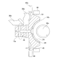
- FIG. 2 is a cross-sectional view of the trunnion and the outer ring constituting the power roller unit of the first example of the embodiment of the present invention.
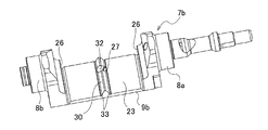
- FIG. 3 is a perspective view showing the trunnion constituting the power roller unit of the first example of the embodiment of the present invention as seen from the radially inner side of the input disk and the output disk.
- FIG. 4A is a partial cross-sectional view showing the shape of the protrusion formed on the trunnion side in the first example
- FIG. 4B is the shape of the concave groove formed on the outer ring side in the first example
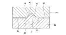
- FIG. FIG. 5 is a partial cross-sectional view showing an engagement state between the protrusion shown in FIG. 4 (A) and the concave groove shown in FIG. 4 (B).
- FIG. 6 is a partial cross-sectional view for explaining the concept of the gap of the engaging portion between the protrusion and the groove in the first example.
- FIG. 7 is a diagram showing the influence of the curvature radius of the cross-sectional shape of the side surface of the ridge on the wear of the engaging portion between the ridge and the groove in the first example.
- FIG. 8 shows a situation in which the size of the gap between the protrusion and the groove in the first example leads to a sudden change in the gear ratio at the moment when the torque passing through the half-toroidal continuously variable transmission is reversed.
- FIGS. 9A and 9B are cross-sectional views showing two examples of a method of finishing the step surface formed on the outer peripheral edge of the outer ring of the outer ring of the first example.
- FIG. 10 is a cross-sectional view illustrating a state in which finishing is performed on the outer ring of the concave portion and the groove of the outer ring, the outer ring raceway, and the support shaft of the first example.
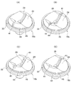
- FIG. 11A to 11D are perspective views showing four examples of positioning recesses provided on the outer surface of the outer ring of the first example.
- FIG. 12A and FIG. 12B are cross-sectional views for explaining the structure of the stopper for regulating the inclination angle of the power roller in the first example.
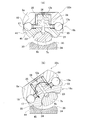
- FIG. 13 (A) is a cross-sectional view of the outer ring constituting the power roller unit of the second example of the embodiment of the present invention
- FIG. 13 (B) is a view of this outer ring from the lower side of FIG. 13 (A). It is a perspective view shown in the state.
- FIG. 14 is a perspective view for explaining a method of forming a recess, a groove, and a step surface on the outer surface of the outer ring of the second example.
- FIG. 15A is a perspective view showing a state in the middle of gripping the outer ring of the second example by the chuck
- FIG. 15B is a cross-sectional view showing a state where gripping of the outer ring by the chuck is completed.
- FIG. 16 is a perspective view for explaining a finishing process applied to the concave portion and the concave groove of the outer ring of the second example using an integrated grindstone.
- FIG. 17A is a perspective view for explaining the finishing process applied to the recess of the outer ring of the second example
- FIG. 10B shows the finishing process applied to the groove of the outer ring of the second example. It is a perspective view explaining.
- FIG. 16 is a perspective view for explaining a finishing process applied to the concave portion and the concave groove of the outer ring of the second example using an integrated grindstone.
- FIG. 17A is a perspective view for explaining the finishing process applied to the recess of the outer ring of the second example
- FIG. 10B shows the
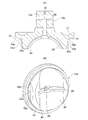
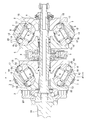
- FIG. 18 is a cross-sectional view showing a half-toroidal continuously variable transmission of a first example having a conventional structure.
- FIG. 19 is a cross-sectional view taken along the line aa in FIG.
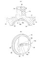
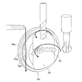
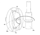
- FIG. 20 is a perspective view of the power roller unit constituting the half-toroidal continuously variable transmission of the second example of the conventional structure as seen from the radially outer side of the input disk and the output disk.
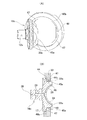
- FIG. 21 is a front view of a second example of a power roller unit having a conventional structure, as viewed from the circumferential direction of an input disk and an output disk.
- FIG. 22 is a plan view of the power roller unit of the second example of the conventional structure as viewed from above in FIG. FIG.
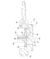
- FIG. 23 is a side view of the power roller unit of the second example having the conventional structure as viewed from the right side of FIG. 24 is a cross-sectional view taken along the line bb of FIG. 25 is a cross-sectional view taken along the line cc of FIG.
- FIG. 26 is a cross-sectional view seen from the same direction as FIG. 24, exaggeratingly showing a state in which the trunnion is elastically deformed based on the thrust load applied from the power roller in the second example of the conventional structure.
- the half-toroidal continuously variable transmission of this example basically includes at least one pair of disks (see FIG. 18) each composed of an input disk 2 and an output disk 5, a plurality of trunnions 7b, and trunnions 7b. And the same number of power rollers 6a (see FIG. 20) and the same number of thrust roller bearings 13a as thrust rolling bearings.
- the present invention relates to a structure of a power roller unit 22a including at least a trunnion 7b, a power roller 6a, and a thrust rolling bearing (thrust ball bearing) 13a among the half-toroidal continuously variable transmission, particularly the trunnion 7b and the thrust rolling bearing 13a. It is characterized in that the structure of the outer ring 16b that constitutes is devised.
- the power roller unit 22a further includes a radial rolling bearing (radial needle bearing) 25 that rotatably supports the power roller 6a around a support shaft 12a provided at the center of the inner surface of the outer ring 16b.
- the input disk 2 and the output disk 5 are supported concentrically with each other so that they can be rotated relative to each other in a state where the axial side surfaces of the toroidal curved surfaces each having an arc cross section are opposed to each other.
- the input disk 2 is supported by the input rotating shaft 1 and the output disk 5 is supported by the output cylinder 3 supported around the input rotating shaft 1 so as to be relatively rotatable.
- the output disk 5 can also be supported around the input rotary shaft 1 so as to be capable of direct relative rotation.
- the output disk 5 is integrated and disposed at the intermediate portion of the input rotary shaft 1, and both axial side surfaces thereof are opposed to one axial side surface of the input disk 2 disposed at both ends of the input rotary shaft 1.
- the trunnions 7 b are located between the axial side surfaces of the input disk 2 and the output disk 5, and are installed at a plurality of locations in the circumferential direction of the input disk 2 and the output disk 5.
- Each trunnion 7b exists between a pair of tilting shafts 8a and 8b provided concentrically with each other at both ends and the tilting shafts 8a and 8b, and at least the input disk 2 and the output disk 5
- the inner side surface in the radial direction is parallel to the central axis of the tilting shafts 8a and 8b, and the central axis existing outside the central direction of the tilting shafts 8a and 8b in the radial direction of the input disk 2 and the output disk 5
- a supporting beam portion 9b having a cylindrical convex surface 23.
- the tilt shafts 8a and 8b are connected by a support beam portion 9b.
- the tilting shafts 8a and 8b of the trunnion 7b are pivotally supported via a radial needle bearing 11 with respect to the support plate 10 so as to be twisted with respect to the central axes of the input disk 2 and the output disk 5 (see FIG. 18), the trunnion 7b is installed so as to be able to swing and swing around the tilting shaft 8.
- the power roller 6a is rotatably supported on the inner side surface of the trunnion 7b via a thrust ball bearing 13a, and the respective circumferential surfaces formed as spherical convex surfaces are respectively contacted with one side surface in the axial direction of the input disk 2 and the output disk 5. (See FIG. 18).
- the thrust ball bearing 13a is installed between the support beam portion 9b of the trunnion 7b and the outer surface of the power roller 6a.
- the thrust ball bearing 13a is provided on the support beam portion 9b side, and includes an outer ring 16b having an inner surface provided with an outer ring raceway 17 and an outer side provided with a recess 24, an outer ring raceway 17 of the outer ring 16b, and a power roller 6a.
- a plurality of balls 18 which are rolling elements are provided so as to be able to roll between the inner ring raceway 15 provided on the outer side surface.
- the outer ring 16b of the thrust rolling bearing 13a is manufactured by subjecting a metal material such as medium carbon steel or bearing steel to cutting or heat treatment.
- a power roller 6a is rotatably supported around a support shaft 12a integrally provided at the center of the inner surface of the outer ring 16b via a radial needle bearing 25 (see FIGS. 24 and 25) that is a radial rolling bearing. Is done.
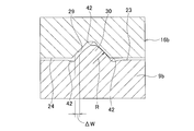
- the power roller 6a is related to the axial direction of the input disk 2 and the output disk 5 with respect to the trunnion 7b by engaging the concave portion 24 provided on the outer surface of the outer ring 16b with the cylindrical convex surface 23 of the support beam portion 9b. It is supported so as to be able to swing and displace (see FIG. 18). Further, on the inner surface of the recess 24 provided on the outer surface of the outer ring 16b, a concave groove 29 formed in the circumferential direction centering on the support beam portion 9b, and a ridge 30 formed on the outer peripheral surface of the support beam portion 9b. To limit the axial displacement of the support beam portion 9b.
- the concave groove 29 provided on the outer surface of the outer ring 16b is formed in a tapered shape with a wide opening and a narrow bottom.
- the cross-sectional shape of the inner surface on both sides of the groove 29 is a straight line as shown in FIGS. Note that an angle ⁇ (see FIG. 4B) formed by the extension line of the inner surface and the recess 24 is about 45 ° (40 ° to 50 °).
- the bottom of the concave groove 29 is formed as an extension line of inner side surfaces on both sides of the concave groove 29 and a relief concave portion 42 that is recessed from an arc surface that smoothly connects these inner side surfaces. Thus, the finishing of these inner surfaces is facilitated.
- the protrusion 30 formed on the outer peripheral surface of the support beam portion 9b is formed in a tapered shape with a wide base portion and a narrow tip portion.
- the outer side surfaces on both sides of the protrusion 30 are formed as partial arcs curved in a direction protruding toward the inner side surfaces on both sides of the concave groove 29 as shown in FIGS.
- the radius of curvature R of this partial arc is 2 mm or more.
- the portion of the outer peripheral surface of the support beam portion 9b that sandwiches the ridge 30 from both axial sides is a relief recess 42 that is recessed from the cylindrical convex surface 22 of the support beam portion 9b, and the outer surface of the ridge 30 is finished. Ease of processing is achieved.
- the outer surface of the ridge 30 and the cylindrical convex surface 22 are also processed at the same time as in the case of the concave portion 24 and the concave groove 29.
- the grinding process for finishing is performed by grinding the outer surface of the ridge 30 and the cylindrical convex surface 22 with an integrated grindstone. Thereby, the positional accuracy of the outer surface of the protrusion 30 and the cylindrical convex surface 22 is ensured.
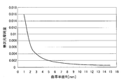
- the outer surface of the protrusion 30 is formed regardless of the processing error between the outer surface of the protrusion 30 and the inner surface of the groove 29 by making the cross-sectional shape of the outer surface of the protrusion 30 a convex arc. It is possible to suppress wear of the rubbing portion between the groove 29 and the inner surface of the groove 29. That is, if the outer side surface of the ridge 30 and the inner side surface of the concave groove 29 are flat surfaces having a linear cross-sectional shape, the surface pressure of the contact portion between these surfaces can be kept low. However, due to processing errors and the like, it is difficult to make the outer surface of the ridge 30 and the inner surface of the concave groove 29 facing each other completely parallel.
- the cross-sectional shape of the outer surface of the protrusion 30 is a convex arc, but it is desirable to secure a curvature radius R of 2 mm or more of the partial arc that is the convex arc.
- Table 1 and FIG. 7 show the influence of the radius of curvature R of the partial arc on the wear amount of the rubbing portion between the outer side surface of the protrusion 30 and the inner side surface of the groove 29.
- the width dimension of the concave groove 29 is slightly larger than the width dimension of the protrusion 30.
- the size relationship between the width dimensions is such that the positions of the support beam portions 9b in the radial direction coincide with each other and the cylindrical convex surface 22 and the concave portion 24 are in contact with each other. This is the case when compared.
- the protrusion 30 does not bite into the concave groove 29 in a state where the cylindrical convex surface 22 and the concave portion 24 are in contact with each other, and the swing of the outer ring 16b with respect to the support beam portion 9b. Dynamic displacement is performed smoothly. Further, the power roller 6a (see FIG.
- the width of the groove 29 is larger than the width of the protrusion 30 by the portion indicated by ⁇ W in FIG. 6 at the portions where the positions of the support beam portions 9b in the radial direction coincide with each other.
- the amount that the outer ring 16b can be displaced in the axial direction of the support beam portion 9b with respect to the support beam portion 9b is limited to ⁇ W. .
- the extent to which the width of the concave groove 29 is made larger than the width of the ridge 30 ( ⁇ W) is as small as possible within a range in which the magnitude relation of the width dimension is not reversed regardless of manufacturing errors, specifically 0. It is necessary to suppress it to 0.050 mm or less. If the width difference ( ⁇ W) is suppressed to 0.050 mm or less, the amount of displacement of the power roller 6a in the axial direction of the trunnion 7b can be suppressed to a small extent regardless of the movement of the actuator 21 (see FIG. 19). Thereby, when the direction of torque transmission by the half-toroidal continuously variable transmission is reversed, it is possible to prevent the driver from feeling uncomfortable by performing an unintended shift operation.
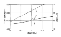
- FIG. 8 shows a state in which a half-toroidal-type continuously variable transmission, a planetary gear mechanism, and a clutch device are combined, and a vehicle equipped with a continuously variable transmission that switches between a low speed mode and a high speed mode by this clutch device.
- the horizontal axis in FIG. 8 represents elapsed time
- the left vertical axis represents engine speed (rotational speed)
- the right vertical axis represents vehicle speed.
- the chain line ⁇ indicates the vehicle speed
- the solid line ⁇ indicates the engine speed when the width difference ( ⁇ W) between the concave groove 29 and the protrusion 30 is 0.125 mm
- the broken line ⁇ indicates the width difference ( ⁇ The engine speed when W) is 0.050 mm is shown.
- the clutch device is switched from the low speed mode state to the high speed mode state. As a result, the direction of torque transmission by the half-toroidal continuously variable transmission is reversed.
- the transmission ratio of the half toroidal continuously variable transmission can be reduced even when the torque transmission direction is reversed. Since it does not change regardless of the movement, the engine speed does not increase rapidly and does not give the driver a sense of incongruity.
- the support beam portion 9b installs the outer ring 16b. Elastically deforms into a circular arc with a concave side. As a result, as shown by an arrow T in FIG. 5, the protrusion 30 is displaced in the direction of coming out of the groove 29, and the gap between the outer surface of the protrusion 30 and the inner surface of the groove 29 tends to widen. . However, the actual spread amount is slight.
- the gap tends to widen, so that the power roller 6a does not transmit torque and the support beam portion 9b and the outer ring 16b are not elastically deformed. Even when ( ⁇ W) is suppressed to 0.050 mm or less, the ridge 30 is not sandwiched between the inner surfaces of the concave groove 29 when transmitting a large torque, and the support beam portion 9b is the center. The oscillating displacement of the outer ring 16b is smoothly performed. Also, when the torque transmitted by the half-toroidal continuously variable transmission is large, even if the engine speed fluctuates due to a slight change in the gear ratio, the driver feels a little strange compared to when the torque is low. It does n’t matter.
- a circular central recess 31 having an opening diameter larger than the width dimension of the groove 29 is formed in the circumferential center of the groove 29, which is aligned with the upstream end opening of the downstream lubricating oil passage 28.
- a notch 32 is formed at the center in the circumferential direction of the ridge 30 that is aligned with the downstream end opening of the upstream lubricating oil passage 27.
- the lubricating oil supply to the thrust ball bearing 13a and the radial needle bearing 25 through the upstream lubricating oil flow path 27 and the downstream lubricating oil path 28 is caused by the oscillation displacement of the outer ring 16b around the support beam portion 9b. Regardless of, it can be performed stably.
- the difference in width ( ⁇ W) between the concave groove 29 and the protrusion 30 is suppressed to 0.050 mm or less.
- the concentricity between the concave portion 24 provided on the outer surface of the outer ring 16b and the concave groove 29 formed on the inner surface of the concave portion 24 is 0.015 mm or less, preferably 0.010 mm or less, more preferably 0. It is necessary to regulate to 0.005 mm or less.
- the recess 24 and the groove 29 are finished by grinding with an integrated grindstone.
- the general-purpose grindstone since the general-purpose grindstone has a large contact area and a large rotational resistance, its use may reduce the efficiency of the finishing process and increase the manufacturing cost.
- the concave portion 24 and the concave groove 29 by simultaneously grinding with a separate grindstone with one chuck.
- the outer ring 16b in order to ensure the coaxiality between the concave portion 24 and the concave groove 29, the outer ring 16b needs to be chucked with high accuracy when finishing the concave portion 24 and the concave groove 29. .
- the trunnions 7b installed in different cavities are synchronized with each other by the same angle in the reverse direction (the same direction with respect to the direction of change in the gear ratio).
- the installation position of the power roller 6a is regulated with high accuracy. For this reason, it is necessary to regulate the size and shape of each part of the power roller unit 22a with high accuracy, particularly between the power roller units 22a incorporated in the same half-toroidal continuously variable transmission.
- a stepped portion 33 is provided over the entire circumference on the outer peripheral edge of the outer surface of the outer ring 16b as a reference surface when finishing the outer ring 16b.
- the concave portion 24 and the concave groove 29 are simultaneously formed on the outer surface of the outer ring 16b by cutting, and after heat treatment, the outer peripheral edge of the outer surface of the outer ring 16b is cut over the entire circumference to form the step portion 33.
- a finishing process such as grinding or hard turning is performed on the radial step surface 44 and the axial step surface 45 constituting the step portion 33 and the outer peripheral surface of the outer ring 16b.
- the radial step surface 44 and the axial step surface 45 of the step portion 33 and the outer peripheral surface of the outer ring 16b are finished, and the radial step surface of the support shaft 12a with respect to the rotation center axis. 44 and the parallelism of the axial step surface 45 and the outer peripheral surface of the outer ring 16b with respect to the rotation center axis of the support shaft 12a are improved.
- two-step chamfered portions 39a and 39b are provided on the inner peripheral edge of the opening portion of the downstream lubricating oil passage 28. Provided. However, if the roundness of the finishing process of the stepped portion 33 can be ensured, a single chamfered portion can be used.
- the inner surface of the outer ring 16b (the left side surface of FIG. 9B) is suppressed by the backup jig 43, and the outer peripheral surface of the support shaft 12a is gripped by the chuck 40.
- the outer ring 16b can be rotated, and the stepped portion 33 and the outer peripheral surface of the outer ring 16b can be finished.
- the axial end surface of the positioning jig 46 is abutted against the radial stepped surface 44, and the axial direction of the support shaft 12 a is related.
- the outer circumferential surface of the outer ring 16b is gripped by the chuck 40a, whereby positioning (centering) in the radial direction of the outer ring 16b can be achieved.
- positioning recesses for positioning the chuck 40a in the circumferential direction at two positions spaced in the radial direction of the outer surface of the outer ring 16b. 41 is provided.
- Such a positioning recess 41 only needs to be able to position the chuck 40a in the circumferential direction, and various structures shown in FIGS. 11A to 11D can be arbitrarily employed.
- a long groove in the axial direction of the support shaft 12a is provided in the inner peripheral edge of the stepped portion 33 at two positions on the opposite side in the radial direction while being recessed radially inward.
- the concave groove 29 is formed across the width direction of the outer ring 16b, that is, in the state where the outer ring 16b is open at both end edges in the width direction, and both end portions in the width direction of the concave groove 29 are positioned.
- a recess 41 is provided.
- a concave groove different from the concave groove 29 is formed in the width direction at two positions in the width direction on the outer surface of the outer ring 16b to form the positioning concave portion 41.
- pin holes are provided at two positions in the width direction on the outer surface of the outer ring 16b to form positioning recesses 41.
- the convex portion provided on the chuck 40a side is engaged with the positioning concave portion 41 of the outer ring 16b, thereby positioning the chuck 40a in the circumferential direction of the outer ring 16b.
- the outer ring 16b is rotated by rotating the chuck 40a with the outer peripheral surface of the outer ring 16b gripped by the chuck 40a, and the outer ring raceway 17 is rotated by the grindstone 38a.
- the outer peripheral surface of 12a with the grindstone 38b By grinding the outer peripheral surface of 12a with the grindstone 38b, the outer ring raceway 17 and the outer peripheral surface of the support shaft 12a can be finished.
- the concave portion 24 and the concave groove 29 are ground by the integrated grindstone 38c so that the concave portion 24 and the concave groove 29 can be finished.
- the shifting operation of the half toroidal continuously variable transmission can be more reliably stabilized. That is, in this example, with the radial stepped surface 44 and the axial stepped surface 45 of the stepped portion 33 formed on the outer peripheral edge of the outer ring 16b as the reference plane, the recessed portion 24 and the recessed groove 29, the outer ring raceway 17, and The outer peripheral surface of the support shaft 12a can be simultaneously finished with a single chuck.
- the concentricity between the concave portion 24 and the concave groove 29 can be improved to 0.015 mm or less, preferably 0.010 mm or less, more preferably 0.005 mm or less, and the outer ring 16b supports the trunnion 7b.
- the amount ( ⁇ W) that can be displaced in the axial direction of the support beam portion 9b with respect to the beam portion 9b can be suppressed to 0.050 mm or less.
- the parallelism between the recess 24 and the outer ring raceway 17, the perpendicularity between the recess 24 and the support shaft 12a, and the error in the assembly height of the power roller 6a with respect to the trunnion 7b are also 0.015 mm or less, preferably 0. 0.010 mm or less, more preferably 0.005 mm or less.
- the half-toroidal continuously variable transmission of the present example includes a synthetic resin stopper 34 having a contact surface 35.
- the stopper 34 is configured so that the trunnion 7b is tilted in a pair in a state where the power roller unit 22a is assembled in a fixed part (see FIG. 19) such as a casing of the half toroidal continuously variable transmission in the half toroidal continuously variable transmission.
- the inclination angle of the trunnion 7b is limited to a certain range.
- the shape of the stopper 34 including the contact surface 35 is arbitrary as long as the contact surface 35 can receive the stepped portion 33 when the trunnion 7b is swung to the allowable limit. is there.
- members existing between the rolling contact portion (traction portion) between the power roller 6a and the inner surfaces of the input disk 2 and the output disk 5 and the stopper 34 are the power roller 6a, the ball of the thrust ball bearing 13a, and The outer ring 16b alone is smaller than the structure described in Japanese Utility Model Laid-Open No. 6-43404, and the distance therebetween is also short. Therefore, the inclination angle of the power roller 6a with respect to the input disk 2 and the output disk 5 can be regulated more accurately.
- other configurations and operations including the overall structure of the half-toroidal continuously variable transmission are the same as the conventional structure.
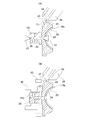
- FIG. 13 to 17 show a second example of the embodiment of the present invention.
- the outer peripheral surface of the outer ring 16c in addition to the stepped portion 33 provided on the outer peripheral surface of the outer ring 16c over the entire periphery, the outer peripheral surface of the outer ring 16c A pair of left and right step portions 33a parallel to the axial direction of the support beam portion 9b (see FIGS. 2, 3, and 12) of the trunnion 7b engaged with the recess 24 is provided on both sides in the width direction across the recess 24. Is provided. As shown in FIG.
- the stepped portion 33 a is formed by cutting (milling) at the same time as forming the concave portion 24 and the concave groove 29 with one chuck. After that, heat treatment is performed on the outer ring 16c. Further, the end surface of the circumferential protrusion 47 provided on the chuck 40b is abutted against the radial step surface 44 of the step portion 33, thereby positioning the support shaft 12a in the axial direction with the beam portion 48 also received by the chuck 40b. By engaging the axial step surface 45a of the step portion 33a with the positioning in the circumferential direction of the outer ring 16c, the outer ring 16c faces the chuck 40b and is pressed to the right in FIG. 15B. .
- the outer ring 16c is gripped by the chuck 40b, thereby positioning (centering) the outer ring 16c in the radial direction.
- the chuck 40b is rotated, and the outer ring raceway 17 of the outer ring 16c and the outer peripheral surface of the support shaft 12a are ground with a grindstone.
- the concave portion 24 and the concave groove 29 are ground by the integral type grindstone 38c as shown in FIG. 16 without replacing the chuck 40b.
- FIG. 17A after the concave portion 24 is ground over the axial direction of the support beam portion 9b by the grindstone 38d, the concave groove 29 is surrounded by the grindstone 38e as shown in FIG. 17B. Grind over direction.
- the stepped portion 33a is provided on both sides of the outer circumferential surface of the outer ring 16c in the width direction across the concave portion 24. Therefore, unlike the first example of the embodiment, it is not necessary to provide the positioning recess 41 (see FIG. 11) for positioning the chuck in the circumferential direction on the outer surface of the outer ring 16c. Further, the stepped portion 33a is provided in parallel with the central axis of the concave portion 24 having a partial cylindrical surface shape, and the positioning of the stepped portion 33a and the beam portion 48 in the circumferential direction of the outer ring 16c of the chuck 40b is achieved. .
- the step surface 44a may be a surface that contacts the contact surface 35 of the stopper 34 (see FIG. 12).
- Other configurations and operations are the same as in the first example of the embodiment.
- the present invention is not only for automatic transmissions for vehicles, but also for automatic transmissions for construction machinery, automatic transmissions for generators used in aircraft, etc., for adjusting the operating speed of various industrial machines such as pumps.
- the present invention can be widely applied to a half toroidal continuously variable transmission used as an automatic transmission.
Abstract
Provided is a power roller unit (22a) the components of which are easily manufactured and managed, and which is easy to assemble, and with which the operation of a half-toroidal continuously variable transmission is stabilized. A trunion (7b) is equipped with inclined rotation shafts (8a, 8b) and a support beam (9b) the insides surface of which is a cylindrical convex surface (23). An outer ring (16b), which forms a thrust rolling bearing (13a) that rotatably supports a power roller (6a) in the support beam (9b), is equipped with a concave part (24) that meshes with the cylindrical convex surface (23), and is equipped with an outer ring raceway (17) and a support shaft (12a). Displacement of the support beam (9b) in the axial direction is restricted by the engagement of a tapered protrusion (30) provided on the inside surface of the support beam (9b) and a tapered concave groove (29) provided in the concave part (24) of the outer ring (16b). In addition, a stepped part (33), which serves as a reference surface when a finishing process is performed on the outer circumferential surfaces of the concave part (24), the concave groove (29), the outer ring raceway (17), and the support shaft (12a), is provided on a portion of the outer circumferential edge on the outside surface of the outer ring (16b).
Description
本発明は、特に、自動車などの車両用変速装置として利用される、ハーフトロイダル無段変速機、特に、ハーフトロイダル無段変速機に揺動可能に支持されるトラニオンと、ハーフトロイダル無段変速機の入力ディスクと出力ディスクの間に挟持され、トルクを伝達するパワーローラをトラニオンに対して回転可能に支持するためのスラスト転がり軸受を構成する外輪とを少なくとも備えるパワーローラユニットに関する。
The present invention relates to a half-toroidal continuously variable transmission, particularly a trunnion that is swingably supported by the half-toroidal continuously variable transmission, and a half-toroidal continuously variable transmission that is used as a transmission for a vehicle such as an automobile. The present invention relates to a power roller unit including at least an outer ring that constitutes a thrust rolling bearing for rotatably supporting a power roller that is sandwiched between an input disk and an output disk and that transmits torque with respect to a trunnion.
車両用変速装置、特に自動車用変速装置の1つとして、入力ディスクと出力ディスクに挟まれたパワーローラの傾き角度を変えることで無段変速を実現するハーフトロイダル無段変速機(CVT)がある(特開2003-214516号公報、特開2007-315595号公報、特開2008-25821号公報、特開2008-275088号公報参照)。このハーフトロイダル無段変速機と遊星歯車機構とクラッチ装置とを組み合わせて、変速機全体としての変速比の調整幅を大きくする構造も知られている(特開2004-169719号公報参照)。
As one of vehicle transmissions, particularly automobile transmissions, there is a half-toroidal continuously variable transmission (CVT) that realizes a continuously variable transmission by changing the inclination angle of a power roller sandwiched between an input disk and an output disk. (See JP 2003-214516 A, JP 2007-315595 A, JP 2008-25821 A, JP 2008-275088 A). There is also known a structure in which a half-toroidal continuously variable transmission, a planetary gear mechanism, and a clutch device are combined to increase the adjustment range of the transmission ratio of the entire transmission (see JP 2004-169719 A).
図18および図19は、従来のハーフトロイダル無段変速機の第1例を示している。この例では、入力回転軸1の両端寄り部分の周囲に1対の入力ディスク2が、入力回転軸1と同期した回転を可能に支持されている。入力回転軸1の中間部周囲には、出力筒3が、入力回転軸1に対する回転を可能に支持されている。出力筒3の外周面の軸方向中央部には、出力歯車4が固設され、その軸方向両端部には、1対の出力ディスク5が、スプライン係合により、出力筒3と同期した回転を可能に支持されている。
18 and 19 show a first example of a conventional half-toroidal continuously variable transmission. In this example, a pair of input disks 2 are supported around a portion near both ends of the input rotation shaft 1 so as to be able to rotate in synchronization with the input rotation shaft 1. An output cylinder 3 is supported around the intermediate portion of the input rotation shaft 1 so as to be rotatable with respect to the input rotation shaft 1. An output gear 4 is fixed at the axial center of the outer peripheral surface of the output cylinder 3, and a pair of output disks 5 are rotated in synchronization with the output cylinder 3 by spline engagement at both axial ends. Is supported by possible.
それぞれの入力ディスク2と出力ディスク5の組み合わせにおいて、それぞれがトロイド曲面である入力ディスク2の内側面と出力ディスク5の内側面が対向している。また、入力ディスク2と出力ディスク5との間に、それぞれの周面が球状凸面である複数個のパワーローラ6が挟持されている。これらのパワーローラ6は、それぞれトラニオン7に回転可能に支持される。それぞれのトラニオン7は、軸方向両端部に互いに同心に設けられた1対の傾転軸8と、これらの傾転軸8を連結する支持梁部9とを備える。トラニオン7の傾転軸8は、入力ディスク2および出力ディスク5の中心軸に対して捩れの位置にあるように、支持板10に対してラジアルニードル軸受11を介して枢支され、トラニオン7は、傾転軸8を中心として揺動変位可能となっている。
In each combination of the input disk 2 and the output disk 5, the inner surface of the input disk 2 and the inner surface of the output disk 5 are opposed to each other, each of which is a toroidal curved surface. A plurality of power rollers 6 each having a spherical convex surface are sandwiched between the input disk 2 and the output disk 5. Each of these power rollers 6 is rotatably supported by the trunnion 7. Each trunnion 7 includes a pair of tilting shafts 8 provided concentrically with each other at both ends in the axial direction, and support beam portions 9 that connect these tilting shafts 8. The tilting shaft 8 of the trunnion 7 is pivotally supported via a radial needle bearing 11 with respect to the support plate 10 so as to be in a twisted position with respect to the center axis of the input disc 2 and the output disc 5. The rocking displacement is possible around the tilting axis 8.
それぞれのパワーローラ6は、トラニオン7の支持梁部9の内側面に、基半部と先半部とが互いに偏心した支持軸12と、支持梁部9とパワーローラ6の外側面の間にパワーローラ6側から順番に設けられたスラスト玉軸受13とスラストニードル軸受14とを介して、支持軸12の先半部を中心とする回転、および、支持軸12の基半部を中心とする若干の揺動変位を可能に支持されている。スラスト玉軸受13は、パワーローラ6に加わるスラスト方向の荷重を支承しつつ、パワーローラ6の回転を許容するもので、パワーローラ6の外側面に形成された内輪軌道15と、外輪16の内側面に形成された外輪軌道17と、これらの軌道の間に転動可能に設けられた複数個の玉18とにより構成される。また、スラストニードル軸受14は、パワーローラ6からスラスト玉軸受13の外輪16に加わるスラスト荷重を支承しつつ、外輪16および支持軸12の先半部が、支持軸12の基半部を中心に揺動することを許容するものである。なお、本例では、パワーローラ6とトラニオン7とスラスト玉軸受13とスラストニードル軸受14とによりパワーローラユニットが構成される。
Each power roller 6 includes a support shaft 12 in which the base half and the front half are eccentric from each other on the inner side surface of the support beam portion 9 of the trunnion 7, and between the support beam portion 9 and the outer surface of the power roller 6. Through the thrust ball bearing 13 and the thrust needle bearing 14 provided in order from the power roller 6 side, the rotation about the front half of the support shaft 12 and the base half of the support shaft 12 are centered. It is supported so that a slight swing displacement is possible. The thrust ball bearing 13 supports the rotation of the power roller 6 while supporting a load in the thrust direction applied to the power roller 6, and the inner ring raceway 15 formed on the outer surface of the power roller 6 and the inner ring 16 The outer ring raceway 17 is formed on the side surface, and a plurality of balls 18 are provided between these raceways so as to be able to roll. Further, the thrust needle bearing 14 supports the thrust load applied to the outer ring 16 of the thrust ball bearing 13 from the power roller 6, and the front half of the outer ring 16 and the support shaft 12 is centered on the base half of the support shaft 12. It is allowed to swing. In this example, the power roller unit, the trunnion 7, the thrust ball bearing 13, and the thrust needle bearing 14 constitute a power roller unit.
このようなハーフトロイダル無段変速機の運転時には、駆動軸19により、一方(図18の左方)の入力ディスク2が押圧装置20を介して回転駆動される。この結果、入力回転軸1の両端部に支持された1対の入力ディスク2が、互いに近づく方向に押圧されつつ同期して回転する。そして、この回転が、パワーローラ6を介して出力ディスク5に伝わり、出力歯車4から取り出される。入力回転軸1と出力歯車4との間の変速比を変える場合は、油圧式のアクチュエータ21によりトラニオン7を傾転軸8の軸方向に変位させる。この結果、パワーローラ6の周面と入力ディスク2および出力ディスク5の内側面との転がり接触部(トラクション部)に作用する、接線方向の力の向きが変化して、転がり接触部にサイドスリップが発生する。そして、この力の向きの変化に伴って、それぞれのトラニオン7が、傾転軸8を中心に揺動し、パワーローラ6の周面と入力ディスク2および出力ディスク5の内側面との接触位置が変化する。パワーローラ6の周面を、入力ディスク2の内側面の径方向外寄り部分と、出力ディスク5の内側面の径方向内寄り部分とに転がり接触させれば、入力回転軸1と出力歯車4との間の変速比が増速側になる。これに対して、パワーローラ6の周面を、入力ディスク2の内側面の径方向内寄り部分と、出力ディスク5の内側面の径方向外寄り部分とに転がり接触させれば、入力回転軸1と出力歯車4との間の変速比が減速側になる。
When operating such a half-toroidal continuously variable transmission, one input disk 2 (left side in FIG. 18) is rotationally driven by the drive shaft 19 via the pressing device 20. As a result, the pair of input disks 2 supported at both ends of the input rotating shaft 1 rotate synchronously while being pressed toward each other. This rotation is transmitted to the output disk 5 through the power roller 6 and is taken out from the output gear 4. When changing the gear ratio between the input rotary shaft 1 and the output gear 4, the trunnion 7 is displaced in the axial direction of the tilt shaft 8 by the hydraulic actuator 21. As a result, the direction of the tangential force acting on the rolling contact portion (traction portion) between the peripheral surface of the power roller 6 and the inner surface of the input disc 2 and the output disc 5 changes, and the side slip occurs on the rolling contact portion. Will occur. As the direction of the force changes, each trunnion 7 swings about the tilting shaft 8, and the contact position between the peripheral surface of the power roller 6 and the inner surfaces of the input disk 2 and the output disk 5. Changes. If the circumferential surface of the power roller 6 is brought into rolling contact with the radially outer portion of the inner surface of the input disk 2 and the radially inner portion of the inner surface of the output disk 5, the input rotary shaft 1 and the output gear 4 The gear ratio between and is on the speed increasing side. On the other hand, if the peripheral surface of the power roller 6 is brought into rolling contact with the radially inward portion of the inner surface of the input disk 2 and the radially outward portion of the inner surface of the output disk 5, the input rotating shaft The gear ratio between 1 and the output gear 4 is on the deceleration side.
このようなハーフトロイダル無段変速機の運転時に、動力の伝達に供される、入力ディスク2、出力ディスク5およびパワーローラ6が、押圧装置20が発生する押圧力に基づいて弾性変形する。そして、この弾性変形に伴って、入力ディスク2および出力ディスク5が軸方向に変位する。また、押圧装置20が発生する押圧力は、ハーフトロイダル無段変速機により伝達するトルクが大きくなるほど大きくなり、それに伴って、入力ディスク2、出力ディスク5およびパワーローラ6の弾性変形量も大きくなる。したがって、トルクの変動に拘らず、入力ディスクおよび出力ディスク5の内側面とパワーローラ6の周面との接触状態を適正に維持するために、トラニオン7に対してパワーローラ6を、入力ディスク2および出力ディスク5の軸方向に変位させる機構が必要になる。従来構造の第1例の場合、パワーローラ6を支持した支持軸12の先半部をその基半部を中心として揺動変位させることにより、パワーローラ6を入力ディスク2および出力ディスク5の軸方向に変位させるようにしている。しかしながら、このような構造は複雑となり、パワーローラユニットの部品製作、部品管理、組立作業がいずれも面倒になることから、ハーフトロイダル無段変速機の製造コストが嵩んでしまう。
When the half-toroidal continuously variable transmission is operated, the input disk 2, the output disk 5, and the power roller 6 that are used for power transmission are elastically deformed based on the pressing force generated by the pressing device 20. And with this elastic deformation, the input disk 2 and the output disk 5 are displaced in the axial direction. Further, the pressing force generated by the pressing device 20 increases as the torque transmitted by the half-toroidal continuously variable transmission increases, and the elastic deformation amount of the input disk 2, the output disk 5, and the power roller 6 increases accordingly. . Therefore, in order to maintain the contact state between the inner surface of the input disk and the output disk 5 and the peripheral surface of the power roller 6 regardless of torque fluctuation, the power roller 6 is connected to the trunnion 7 with respect to the input disk 2. In addition, a mechanism for displacing the output disk 5 in the axial direction is required. In the case of the first example of the conventional structure, the front half of the support shaft 12 that supports the power roller 6 is oscillated and displaced about the base half thereof, so that the power roller 6 is moved to the shafts of the input disk 2 and the output disk 5. It is displaced in the direction. However, such a structure is complicated, and the production of the parts of the power roller unit, the parts management, and the assembly work are all complicated, and the manufacturing cost of the half-toroidal continuously variable transmission increases.
特開2008-25821号公報には、このような問題を解決するために、パワーローラを入力ディスクおよび出力ディスクの軸方向に変位させるための構造を改良した従来構造の第2例が開示されている。図20~図25に示すように、従来構造の第2例を構成するトラニオン7aは、両端部に互いに同心に設けられた1対の傾転軸8a、8bと、これらの傾転軸8a、8bの間に存在し、少なくとも入力ディスク2および出力ディスク5の径方向(図24および図25の上下方向)に関する内側(図24および図25の上側)の側面を円筒状凸面23とした、支持梁部9aとを備える。傾転軸8a、8bは、それぞれラジアルニードル軸受11aを介して、支持板10(図19参照)に、揺動および軸方向の変位を可能に支持されている。
Japanese Patent Laid-Open No. 2008-25821 discloses a second example of a conventional structure in which the structure for displacing the power roller in the axial direction of the input disk and the output disk is improved in order to solve such a problem. Yes. As shown in FIGS. 20 to 25, the trunnion 7a constituting the second example of the conventional structure includes a pair of tilting shafts 8a and 8b concentrically provided at both ends, and these tilting shafts 8a, 8b, and a cylindrical convex surface 23 on the inner side (upper side in FIGS. 24 and 25) in the radial direction (the vertical direction in FIGS. 24 and 25) of at least the input disk 2 and the output disk 5 And a beam portion 9a. The tilting shafts 8a and 8b are supported on the support plate 10 (see FIG. 19) via a radial needle bearing 11a, respectively, so as to be swingable and axially displaceable.
また、円筒状凸面23の中心軸Xは、図21および図24に示すように、傾転軸8a、8bの中心軸Yと平行で、これらの傾転軸8a、8bの中心軸Yよりも、入力ディスク2および出力ディスク5の径方向に関して外側(図24および図25の下側)に存在する。また、支持梁部9aとパワーローラ6aの外側面との間に設けるスラスト玉軸受13aを構成する外輪16aの外側面に、部分円筒面状の凹部24を、この外側面を径方向に横切る状態で設けている。そして、凹部24と、支持梁部9aの円筒状凸面23とを係合させることにより、外輪16aは、トラニオン7aに対して入力ディスク2および出力ディスク5の軸方向に関する揺動変位を可能に支持される。
Further, as shown in FIGS. 21 and 24, the center axis X of the cylindrical convex surface 23 is parallel to the center axis Y of the tilt axes 8a and 8b, and is more than the center axis Y of these tilt axes 8a and 8b. In the radial direction of the input disk 2 and the output disk 5, it exists outside (the lower side of FIGS. 24 and 25). Further, a concave portion 24 having a partially cylindrical surface is formed on the outer surface of the outer ring 16a constituting the thrust ball bearing 13a provided between the support beam portion 9a and the outer surface of the power roller 6a so as to cross the outer surface in the radial direction. Is provided. Then, by engaging the concave portion 24 with the cylindrical convex surface 23 of the support beam portion 9a, the outer ring 16a supports the trunnion 7a so as to be able to swing and displace in the axial direction of the input disk 2 and the output disk 5. Is done.
また、支持軸12aは、外輪16aの内側面中央部に、外輪16aと一体に設けられており、パワーローラ6aが、支持軸12aの周囲に、ラジアルニードル軸受25を介して、回転可能に支持されている。さらに、トラニオン7aの内側面のうち、支持梁部9aの両端部と1対の傾転軸8a、8bとの連続部に、互いに対向する1対の段差面26が設けられている。そして、これらの段差面26と、スラスト玉軸受13aの外輪16aの外周面とを、当接もしくは近接対向させており、パワーローラ6aから外輪16aに加わるトラクション力が、いずれかの段差面26で支承されるようになっている。なお、本例では、パワーローラ6aとトラニオン7aとスラスト玉軸受13aとラジアルニードル軸受25とによりパワーローラユニット22が構成される。
The support shaft 12a is provided integrally with the outer ring 16a at the center of the inner surface of the outer ring 16a, and the power roller 6a is rotatably supported around the support shaft 12a via a radial needle bearing 25. Has been. Further, a pair of stepped surfaces 26 facing each other are provided on the inner surface of the trunnion 7a at a continuous portion between both ends of the support beam portion 9a and the pair of tilting shafts 8a and 8b. These step surfaces 26 and the outer peripheral surface of the outer ring 16a of the thrust ball bearing 13a are brought into contact with or in close proximity to each other, and the traction force applied from the power roller 6a to the outer ring 16a is at any step surface 26. It comes to be supported. In this example, the power roller unit 22 is configured by the power roller 6a, the trunnion 7a, the thrust ball bearing 13a, and the radial needle bearing 25.
従来構造の第2例のハーフトロイダル無段変速機によれば、パワーローラ6aを入力ディスク2および出力ディスク5の軸方向に変位させて、これらの構成部材の弾性変形量の変化に拘らず、パワーローラ6aの周面と入力ディスク2および出力ディスク5との接触状態を適正に維持することができる構造が、簡単かつ低コストに実現される。すなわち、ハーフトロイダル無段変速機の運転時に、入力ディスク2および出力ディスク5、パワーローラ6aの弾性変形に基づき、パワーローラ6aを入力ディスク2および出力ディスク5の軸方向に変位させる必要が生じると、パワーローラ6aを回転可能に支持しているスラスト玉軸受13aの外輪16aが、外側面に設けた部分円筒面状の凹部24と支持梁部9aの円筒状凸面23との当接面を滑らせつつ、円筒状凸面23の中心軸Xを中心として揺動変位する。この揺動変位に基づき、パワーローラ6aの周面のうちで、入力ディスク2および出力ディスク5の軸方向片側面と転がり接触する部分が、入力ディスク2および出力ディスク5の軸方向に変位し、これらの構成部材間の接触状態を適正に維持する。
According to the half-toroidal continuously variable transmission of the second example of the conventional structure, the power roller 6a is displaced in the axial direction of the input disk 2 and the output disk 5, regardless of changes in the amount of elastic deformation of these constituent members. A structure capable of appropriately maintaining the contact state between the peripheral surface of the power roller 6a and the input disk 2 and the output disk 5 is realized simply and at low cost. That is, when the half-toroidal continuously variable transmission is operated, it is necessary to displace the power roller 6a in the axial direction of the input disk 2 and the output disk 5 based on elastic deformation of the input disk 2, the output disk 5, and the power roller 6a. The outer ring 16a of the thrust ball bearing 13a that rotatably supports the power roller 6a slides on the contact surface between the concave portion 24 of the partial cylindrical surface provided on the outer surface and the cylindrical convex surface 23 of the support beam portion 9a. In this manner, the cylindrical convex surface 23 is oscillated and displaced about the central axis X. Based on this oscillating displacement, a portion of the peripheral surface of the power roller 6a that is in rolling contact with one axial side surface of the input disk 2 and the output disk 5 is displaced in the axial direction of the input disk 2 and the output disk 5. The contact state between these components is properly maintained.
円筒状凸面23の中心軸Xは、変速動作の際にトラニオン7aの揺動中心となる傾転軸8a、8bの中心軸Yよりも、入力ディスク2および出力ディスク5の径方向に関して外側に存在する。したがって、円筒状凸面23の中心軸Xを中心とする揺動変位の半径は、変速動作の際の揺動半径よりも大きくなるため、円筒状凸面23の中心軸Xを中心とするパワーローラ6aの揺動変位が入力ディスク2と出力ディスク5との間の変速比の変動に及ぼす影響は、無視できるか、容易に修正できる範囲に留まる。
The center axis X of the cylindrical convex surface 23 exists outside the center axis Y of the tilting shafts 8a and 8b, which are the center of oscillation of the trunnion 7a during the speed change operation, in the radial direction of the input disk 2 and the output disk 5. To do. Accordingly, since the radius of the rocking displacement around the central axis X of the cylindrical convex surface 23 is larger than the rocking radius at the time of the shifting operation, the power roller 6a having the central axis X of the cylindrical convex surface 23 as the center. The influence of the rocking displacement on the fluctuation of the transmission ratio between the input disk 2 and the output disk 5 is negligible or can be easily corrected.
図20~図25に示した従来構造の第2例の場合、従来構造の第1例と比べて、部品製作、部品管理、組立作業がいずれも容易となり、コスト低廉化を図りやすいが、変速動作を安定させる面からは、改良の余地がある。従来構造の第2例では、支持梁部9aを中心とする外輪16aの揺動変位を円滑に行わせるため、支持梁部9aの両端部に1対ずつ設けた、段差面26同士の間隔Dを、外輪16aの外径dよりも少し大きく(D>d)している。したがって、外輪16aおよびパワーローラ6aは、間隔Dと外径dとの差(D-d)の分だけ、支持梁部9aの軸方向に変位可能である。
In the case of the second example of the conventional structure shown in FIGS. 20 to 25, parts manufacturing, parts management, and assembly work are all easier and cost reduction is easier than the first example of the conventional structure. There is room for improvement in terms of stabilizing the operation. In the second example of the conventional structure, the distance D between the step surfaces 26 provided in pairs at both ends of the support beam portion 9a in order to smoothly swing and displace the outer ring 16a around the support beam portion 9a. Is slightly larger than the outer diameter d of the outer ring 16a (D> d). Therefore, the outer ring 16a and the power roller 6a can be displaced in the axial direction of the support beam portion 9a by the difference (D−d) between the distance D and the outer diameter d.
ハーフトロイダル無段変速機を搭載した車両の運転時、パワーローラ6aには入力ディスク2および出力ディスク5から、加速時と減速時(エンジンブレーキの作動時)とで逆方向の力が加わる。この力は、ハーフトロイダル無段変速機の技術分野で「2Ft」として周知である。そして、この力「2Ft」により、パワーローラ6aが、外輪16aとともに、支持梁部9aの軸方向に変位する。この変位の方向は、アクチュエータ21によるトラニオン7(図19参照)の変位方向と同じであり、変位量が0.1mm程度であっても、変速動作が開始される可能性がある。このような原因により開始される変速動作は、運転動作とは直接関連しない変速動作であり、いずれ修正されるとしても、運転者に違和感を与える。特に、ハーフトロイダル無段変速機が伝達するトルクが低い状態で、このような運転者の意図しない変速動作の発生は、運転者に大きな違和感を与えてしまう可能性がある。
During operation of a vehicle equipped with a half-toroidal continuously variable transmission, reverse power is applied to the power roller 6a from the input disk 2 and the output disk 5 during acceleration and deceleration (when the engine brake is activated). This force is known as “2Ft” in the technical field of half-toroidal continuously variable transmissions. The force roller “2Ft” displaces the power roller 6a along with the outer ring 16a in the axial direction of the support beam portion 9a. The direction of this displacement is the same as the direction of displacement of the trunnion 7 (see FIG. 19) by the actuator 21, and there is a possibility that the shifting operation may be started even if the amount of displacement is about 0.1 mm. The shift operation that is started for such a cause is a shift operation that is not directly related to the driving operation, and even if it is corrected anyway, the driver feels uncomfortable. In particular, when the torque transmitted by the half-toroidal continuously variable transmission is low, the occurrence of such a shifting operation not intended by the driver may give the driver a great sense of incongruity.
運転動作とは直接関連しない変速動作の発生を抑えるためには、間隔Dと外径dとの差(D-d)を僅少に、具体的には数十μm程度に抑える必要がある。ただし、ハーフトロイダル無段変速機の運転時には、トラクション部からパワーローラ6a、外輪16aを介して支持梁部9aに加わるスラスト荷重により、トラニオン7aが、図26に誇張して示すように、外輪16aを設置した側が凹となる方向に弾性変形する。そして、この弾性変形の結果、トラニオン7aごとに1対ずつ設けられている段差面26同士の間隔が縮まる。この状態でも、段差面26同士の間隔Dが外輪16aの外径d以下にならないようにするためには、通常状態、すなわちトラニオン7aが弾性変形していない状態での、間隔Dと外径dとの差をある程度確保する必要がある。この結果、特に違和感が大きくなりやすい、低トルクでの運転時に、運転動作とは直接関連しない変速動作が発生しやすくなる。特に、ハーフトロイダル無段変速機と遊星歯車機構とクラッチ装置とを組み合わせ、このクラッチ装置により低速モードと高速モードとを切り換える構造を有する無段変速装置の場合、モードの切り換えに伴って、加速状態のまま、ハーフトロイダル無段変速機を通過するトルクの方向が逆転する。このため、運転動作とは直接関連しない変速動作が発生する可能性が高くなり、運転者に違和感を与えやすい。
In order to suppress the occurrence of a shift operation that is not directly related to the driving operation, it is necessary to suppress the difference (D−d) between the distance D and the outer diameter d to a small extent, specifically to about several tens of μm. However, during operation of the half toroidal continuously variable transmission, the trunnion 7a is exaggerated in FIG. 26 due to the thrust load applied from the traction portion to the support beam portion 9a via the power roller 6a and the outer ring 16a. Is elastically deformed in a direction in which the side on which is installed becomes concave. As a result of this elastic deformation, the gap between the stepped surfaces 26 provided for each trunnion 7a is reduced. Even in this state, in order to prevent the distance D between the stepped surfaces 26 from being equal to or less than the outer diameter d of the outer ring 16a, the distance D and the outer diameter d in the normal state, that is, the state where the trunnion 7a is not elastically deformed. It is necessary to secure a certain amount of difference. As a result, a shifting operation that is not directly related to the driving operation is likely to occur during driving at a low torque, which is particularly likely to cause a sense of discomfort. In particular, in the case of a continuously variable transmission having a structure in which a half-toroidal continuously variable transmission, a planetary gear mechanism, and a clutch device are combined and the low-speed mode and the high-speed mode are switched by the clutch device, The direction of torque passing through the half-toroidal continuously variable transmission is reversed. For this reason, there is a high possibility that a speed change operation not directly related to the driving operation will occur, and the driver is likely to feel uncomfortable.
特開2008-25821号公報には、支持梁部側に設けた円筒状凸面の一部に係止したアンカ駒と、外輪側の凹部の内面に形成したアンカ溝とを係合させることにより、力「2Ft」を支承する構造も記載されている。ただし、この構造の場合、アンカ駒を支持梁部に、力「2Ft」を支承できる程度の強度および剛性を確保して支持固定することが難しく、低コスト化と十分な信頼性の確保が図りにくい。また、円筒状凸面と凹部との互いに整合する部分に形成された、それぞれが断面円弧形である転動溝同士の間に複数個の玉を掛け渡して、力「2Ft」を支承する構造も記載されている。ただし、この構造の場合、力「2Ft」が大きくなり、玉の転動面と転動溝との転がり接触部の面圧が上昇すると、転動溝の内面に圧痕が形成され、トラニオンに対して内輪が揺動変位する際に振動が発生する可能性がある。さらには、支持梁部の外周面に形成した、軸方向両側面が互いに平行な突条と、外輪側の凹部の内面に形成した凹溝とを係合させることにより、力「2Ft」を支承する構造も記載されている。ただし、この構造の場合、突条と凹溝との係合部の隙間を小さくするため、突条の両側面同士の間隔を高精度に仕上げるための研磨加工時に、突条の両側面に研磨焼けに伴う損傷が発生しやすい。すなわち、この研磨加工は、回転させた砥石を、突条の両側面に押し当てることにより行われる。この時、加工面である突条の両側面同士が平行、言い換えれば、突条の両側面が砥石の回転軸に対し垂直であるため、突条の両側面の温度が上昇して研磨焼けが発生しやすくなる。また、この砥石の回転軸の軸方向と押し付け方向とが平行となるため、突条の両側面および円筒状凸面に同時に研磨加工を施すことができず、加工効率が悪く、トラニオン全体の製造コストを上昇させる原因となっている。
In Japanese Patent Application Laid-Open No. 2008-25821, by engaging an anchor piece locked to a part of a cylindrical convex surface provided on the support beam portion side and an anchor groove formed on the inner surface of the concave portion on the outer ring side, A structure for supporting the force “2Ft” is also described. However, in this structure, it is difficult to support and fix the anchor piece to the support beam portion with sufficient strength and rigidity to support the force “2Ft”, thereby reducing costs and ensuring sufficient reliability. Hateful. In addition, a structure in which a plurality of balls are spanned between rolling grooves each having an arcuate cross section formed on a portion where the cylindrical convex surface and the concave portion are aligned with each other, and the force “2 Ft” is supported. Is also described. However, in this structure, when the force “2Ft” increases and the surface pressure of the rolling contact portion between the ball rolling surface and the rolling groove increases, an indentation is formed on the inner surface of the rolling groove, and against the trunnion Therefore, vibration may occur when the inner ring is oscillated and displaced. Furthermore, the force “2 Ft” is supported by engaging the protrusions formed on the outer peripheral surface of the support beam portion and having axially opposite sides parallel to each other and the groove formed on the inner surface of the recess on the outer ring side. The structure to be described is also described. However, in this structure, in order to reduce the gap between the engaging portion of the ridge and the groove, the both sides of the ridge are polished on both sides of the ridge at the time of polishing to finish with high accuracy. Damage due to burning is likely to occur. That is, this polishing process is performed by pressing the rotated grindstone against both side surfaces of the ridge. At this time, both sides of the ridge, which is the processed surface, are parallel to each other, in other words, because both sides of the ridge are perpendicular to the rotation axis of the grindstone, the temperature of both sides of the ridge rises and polishing burns occur. It tends to occur. In addition, since the axial direction of the rotating shaft of this grindstone and the pressing direction are parallel, it is impossible to polish both sides of the ridge and the cylindrical convex surface at the same time. It is the cause that raises.
さらに、ハーフトロイダル無段変速機においては、トラニオンが揺動変位した場合に、パワーローラの周面が入力ディスクおよび出力ディスクの内側面の径方向外方に突出したり、外輪の外周縁やスラスト玉軸受を構成する玉を保持する保持器の外周縁が、入力ディスクおよび出力ディスクの内側面に接触したりしないようにする必要がある。実開平6-43404号公報には、トラニオンの端部に設けられた支持板部の先端部を傾斜縁とし、この傾斜縁と、ハウジングなどに固定されたストッパとを、トラニオンが許容限度まで揺動変位した場合に当接させることで、このトラニオンがそれ以上揺動変位することを阻止するストッパ機構が設けられた構造が記載されている。ただし、この構造の場合、パワーローラの周面と入力ディスクおよび出力ディスクの内側面との転がり接触部と、傾斜縁とストッパとの当接部との間に存在する部材が、パワーローラ、スラスト玉軸受を構成する玉、外輪、および、トラニオンからなり、部材点数が多く、これらの間の距離も長い。したがって、入力ディスクおよび出力ディスクに対するパワーローラの傾斜角度をより高精度に規制する面からは、改良の余地がある。
Further, in a half-toroidal continuously variable transmission, when the trunnion is oscillating and displaced, the peripheral surface of the power roller protrudes radially outward of the inner surface of the input disk and output disk, or the outer peripheral edge of the outer ring and the thrust ball. It is necessary to prevent the outer peripheral edge of the cage that holds the balls constituting the bearing from coming into contact with the inner surfaces of the input disk and the output disk. In Japanese Utility Model Publication No. 6-43404, the tip of the support plate provided at the end of the trunnion has an inclined edge, and the inclined edge and a stopper fixed to the housing or the like are swung to the allowable limit. There is described a structure provided with a stopper mechanism that prevents the trunnion from further oscillating and displacing by being brought into contact in the case of dynamic displacement. However, in this structure, the members existing between the rolling contact portion between the peripheral surface of the power roller and the inner surface of the input disk and the output disk and the contact portion between the inclined edge and the stopper are the power roller, thrust It consists of balls, outer rings, and trunnions constituting a ball bearing, and has a large number of members and a long distance between them. Therefore, there is room for improvement in terms of regulating the inclination angle of the power roller with respect to the input disk and the output disk with higher accuracy.
本発明は、部品製作、部品管理、組み立て作業がいずれも容易となり、コスト低廉化を図りやすく、しかも変速動作を安定させられ、さらに必要に応じて、入力ディスクおよび出力ディスクに対するパワーローラの傾斜角度を規制することができるパワーローラユニット並びに該パワーローラユニットを備えるハーフトロイダル無段変速機を提供することを目的とする。
The present invention makes it easy to manufacture parts, manage parts, and assemble, facilitate cost reduction, stabilize the speed change operation, and further, if necessary, the inclination angle of the power roller with respect to the input disk and output disk It is an object of the present invention to provide a power roller unit capable of regulating the above and a half toroidal continuously variable transmission including the power roller unit.
本発明のハーフトロイダル無段変速機は、少なくとも1対のディスクと、複数のパワーローラと、該パワーローラと同数であり、トラニオンとスラスト転がり軸受を構成する外輪を少なくとも有する、パワーローラユニットとを備える。
A half toroidal continuously variable transmission according to the present invention includes at least a pair of disks, a plurality of power rollers, and a power roller unit having at least the same number of the power rollers and at least an outer ring constituting a trunnion and a thrust rolling bearing. Prepare.
1対のディスクは、それぞれが断面円弧形のトロイド曲面である互いの軸方向片側面同士を対向させた状態で、互いに同心に、相対回転を可能に支持されている。具体的には、該1対のディスクは、ハーフトロイダル無段変速機の入力回転軸の周囲に該入力回転軸と同期した回転を可能に支持された入力ディスクと、前記入力回転軸の周囲に相対回転可能に支持された出力ディスクとにより構成される。典型的には、ハーフトロイダル無段変速機は、前記入力回転軸の両端寄り部分に1対の入力ディスクが配置され、前記入力回転軸の中間部に1対の出力ディスクあるいは一体型の出力ディスクが配置される。
The pair of discs are supported concentrically with each other so that they can rotate relative to each other in a state in which one side surface of each axial direction is a toroidal curved surface having an arc cross section. Specifically, the pair of disks includes an input disk supported around the input rotation shaft of the half toroidal continuously variable transmission so as to be able to rotate in synchronization with the input rotation shaft, and around the input rotation shaft. And an output disk supported so as to be relatively rotatable. Typically, in the half-toroidal continuously variable transmission, a pair of input disks are arranged near both ends of the input rotation shaft, and a pair of output disks or an integrated output disk is arranged in the middle of the input rotation shaft. Is placed.
前記パワーローラユニットを構成するトラニオンは、両端部に互いに同心に設けられた1対の傾転軸と、該傾転軸の間に設けられ、これらの傾転軸を連結する支持梁部とを備える。該支持梁部は、ハーフトロイダル無段変速機内に組み付けられた状態で、ハーフトロイダル無段変速機を構成する1対のディスクの径方向に関する内側に、前記傾転軸の中心軸と平行で、該傾転軸の中心軸よりも前記1対のディスクの径方向に関して外側に存在する中心軸を有する円筒状凸面からなる内側面を備える。
The trunnion constituting the power roller unit includes a pair of tilting shafts concentrically provided at both ends, and a support beam portion provided between the tilting shafts and connecting these tilting shafts. Prepare. The support beam portion is assembled in a half toroidal continuously variable transmission, and is parallel to the central axis of the tilting shaft on the inner side in the radial direction of a pair of disks constituting the half toroidal continuously variable transmission. An inner side surface comprising a cylindrical convex surface having a central axis that exists outside the central axis of the tilt axis in the radial direction of the pair of disks is provided.
前記パワーローラユニットを構成するスラスト転がり軸受は、前記1対のディスクのそれぞれの断面円弧状のトロイド曲面からなる軸方向片側面に当接する、球状凸面からなる周面を備えるパワーローラを、前記支持梁部の内側面に対して回転可能に支持する。該スラスト転がり軸受を構成する外輪は、前記支持梁部の内側面と係合する凹部が設けられた外側面と、前記スラスト転がり軸受の外輪軌道が設けられた内側面と、該内側面中央部に設けられ、前記パワーローラを回転可能に支持する支持軸とを備える。なお、本明細書では、説明の便宜上、パワーローラユニットは、少なくともトラニオンとスラスト転がり軸受を構成する外輪とを備える構造体をいうものとする。一般的には、パワーローラユニットは、前記パワーローラの外側面に設けられた内輪軌道と前記外輪の外輪軌道との間に転動可能に設けられた複数の転動体と、前記パワーローラを前記支持軸の周囲に回転可能に支持するラジカル転がり軸受も含む。なお、製品としては、本発明のパワーローラユニットとパワーローラとの組み合わせについても、パワーローラユニットと称される。
The thrust rolling bearing constituting the power roller unit supports the power roller having a peripheral surface made of a spherical convex surface that abuts one axial side surface made of a toroidal curved surface having a circular arc cross section of each of the pair of disks. It supports so that it can rotate with respect to the inner surface of a beam part. The outer ring constituting the thrust rolling bearing includes an outer surface provided with a recess that engages with an inner side surface of the support beam portion, an inner side surface provided with an outer ring raceway of the thrust rolling bearing, and a central portion of the inner side surface And a support shaft that rotatably supports the power roller. In the present specification, for convenience of explanation, the power roller unit refers to a structure including at least a trunnion and an outer ring constituting a thrust rolling bearing. In general, the power roller unit includes a plurality of rolling elements provided so as to roll between an inner ring raceway provided on an outer surface of the power roller and an outer ring raceway of the outer ring, and the power roller including the power roller. A radical rolling bearing that is rotatably supported around the support shaft is also included. As a product, the combination of the power roller unit and the power roller of the present invention is also referred to as a power roller unit.
特に、本発明のパワーローラユニットにおいては、前記トラニオンの支持梁部の内側面に、前記円筒状凸面の周方向に伸長し、基部の幅が広く先端部の幅が狭いテーパ状の突条が形成されており、前記外輪の外側面の凹部に、該凹部の周方向に伸長し、開口部の幅が広く底部の幅が狭いテーパ状の凹溝が形成されており、該突条と該凹溝の係合により、前記支持梁部の軸方向の変位が制限されている。
In particular, in the power roller unit of the present invention, a tapered protrusion extending in the circumferential direction of the cylindrical convex surface on the inner surface of the support beam portion of the trunnion and having a wide base and a narrow tip. Formed in the recess on the outer surface of the outer ring, and is formed with a tapered groove extending in the circumferential direction of the recess and having a wide opening and a narrow bottom. The axial displacement of the support beam portion is limited by the engagement of the concave groove.
また、前記外輪の外側面外周縁部の少なくとも一部に、該外輪をチャックにより把持した状態で、前記凹部および前記凹溝、前記外輪軌道、並びに、前記支持軸の外周面に、研削加工あるいはハードターニング仕上げなどの仕上げ加工を施す際の基準面となる段差部が設けられている。
In addition, at least part of the outer peripheral edge portion of the outer surface of the outer ring, with the outer ring held by a chuck, the recess and the groove, the outer ring raceway, and the outer peripheral surface of the support shaft are ground or A step portion is provided as a reference surface when finishing such as hard turning finish.
前記段差部は、前記外輪の外側面外周縁部のうち、前記凹部を挟む幅方向両側部分に前記支持梁部の軸方向に設けられていることが好ましい。なお、加工の便宜上、前記段差部が、前記外輪の外側面外周縁部に全周にわたって設けられていてもよい。
It is preferable that the stepped portion is provided in the axial direction of the support beam portion on both sides in the width direction sandwiching the concave portion in the outer peripheral edge portion of the outer surface of the outer ring. For convenience of processing, the stepped portion may be provided on the outer peripheral edge portion of the outer surface of the outer ring over the entire circumference.
また、前記外輪の外側面に前記チャックの周方向の位置決めを図るための位置決め凹部が設けられていることが好ましい。
Further, it is preferable that a positioning recess for positioning the chuck in the circumferential direction is provided on the outer surface of the outer ring.
本発明のハーフトロイダル無段変速機は、トロイド曲面である互いの軸方向片側面同士を対向させた状態で、互いに同心に、相対回転を可能に支持された少なくとも1対のディスクと、前記1対のディスクのそれぞれの前記軸方向片側面に当接し、球状凸面からなる周面を備える複数のパワーローラと、該パワーローラと同数である、本発明のパワーローラユニットとを備える。本発明のハーフトロイダル無段変速機においては、前記トラニオンの前記1対の傾転軸は、前記1対のディスクの軸方向片側面同士の間で、該1対のディスクの周方向の複数箇所に、該1対のディスクの中心軸に対して捩れの位置に配置され、前記トラニオンは前記傾転軸を中心とする揺動変位可能に支持されている。
The half-toroidal continuously variable transmission according to the present invention includes at least one pair of discs that are concentrically supported and capable of relative rotation in a state in which one axial side surfaces that are toroidal curved surfaces face each other. A plurality of power rollers that are in contact with the one side surface in the axial direction of each of the pair of disks and that have a peripheral surface made of a spherical convex surface, and the power roller unit of the present invention that is the same number as the power roller. In the half-toroidal continuously variable transmission according to the present invention, the pair of tilting shafts of the trunnion are arranged at a plurality of positions in the circumferential direction of the pair of disks between the axial side surfaces of the pair of disks. Further, the trunnion is disposed at a twisted position with respect to the central axis of the pair of disks, and the trunnion is supported so as to be able to swing and displace around the tilting axis.
好ましくは、本発明のハーフトロイダル無段変速機は、前記トラニオンが前記傾転軸を中心として許容限度まで揺動変位した場合に、前記外輪の段差部が係合する位置に、該外輪の段差部との係合に基づいて前記トラニオンがそれ以上揺動変位することを阻止するストッパが設けられる。
Preferably, the half-toroidal continuously variable transmission according to the present invention is configured such that the step of the outer ring is located at a position where the step portion of the outer ring is engaged when the trunnion is swung to the permissible limit around the tilt shaft. A stopper is provided for preventing the trunnion from further oscillating and displacing based on the engagement with the portion.
本発明のパワーローラユニットの製造方法は、本発明のパワーローラユニットを構成する前記外輪の外側面外周縁部の少なくとも一部に前記段差部を設ける工程、および、該段差部を基準面として位置決めを図った状態で、前記外輪をチャックにより把持し、前記凹部および前記凹溝、前記外輪軌道、並びに、前記支持軸の外周面に、同時に仕上げ加工を施す工程とを備えることを特徴とする。なお、本明細書において、「同時に」加工とは、途中で加工装置を変更することなく、すなわち、途中でチャッキングを行わずに加工を行うことを意味し、凹部および凹溝、外輪軌道、並びに、支持軸の外周面が厳密に同時に行われることまでは要求されておらず、同一工程内で行われる場合を含むものと解釈される。
The method for manufacturing a power roller unit according to the present invention includes the step of providing the stepped portion at least at a part of the outer peripheral edge of the outer surface of the outer ring constituting the power roller unit of the present invention, and positioning the stepped portion as a reference surface. In this state, the outer ring is gripped by a chuck, and the concave portion, the concave groove, the outer ring raceway, and the outer peripheral surface of the support shaft are simultaneously finished. In the present specification, “simultaneously” processing means that processing is performed without changing the processing device in the middle, that is, without chucking in the middle, and the concave and concave grooves, the outer ring raceway, In addition, it is not required that the outer peripheral surface of the support shaft is performed strictly at the same time, and it is interpreted that the case is performed in the same process.
本発明のパワーローラユニットの製造方法において、前記外輪の外側面に、前記チャックの周方向の位置決めを図る位置決め凹部を設ける工程をさらに設けることが好ましい。
In the method for manufacturing a power roller unit of the present invention, it is preferable to further provide a step of providing a positioning recess for positioning the chuck in the circumferential direction on the outer surface of the outer ring.
なお、前記段差部を、前記外輪の外側面外周縁部のうち、前記凹部を挟む幅方向両側部分に設けることが好ましいが、前記段差部を、前記外輪の外側面外周縁部に全周にわたって設けてもよい。
In addition, although it is preferable to provide the said step part in the width direction both-sides part which pinches | interposes the said recessed part among the outer peripheral surface outer peripheral parts of the said outer ring | wheel, the said step part is extended to the outer peripheral surface outer peripheral part of the said outer ring over the perimeter. It may be provided.
本発明により、パワーローラユニットの部品製作、部品管理、組立作業がいずれも容易になり、ハーフトロイダル無段変速機のコスト低廉化を図りやすく、しかもハーフトロイダル無段変速機の変速動作を安定させることができる。さらに、入力ディスクおよび出力ディスクに対するパワーローラの傾斜角度を精度よく規制可能なハーフトロイダル無段変速機が提供される。
The present invention makes it easy to manufacture, manage and assemble parts of the power roller unit, facilitate the cost reduction of the half-toroidal continuously variable transmission, and stabilize the shifting operation of the half-toroidal continuously variable transmission. be able to. Furthermore, a half toroidal continuously variable transmission capable of accurately regulating the inclination angle of the power roller with respect to the input disk and the output disk is provided.
具体的には、外輪の外側面外周縁部の一部に段差部が設けられ、この段差部を基準面として位置決めを図った状態で、外輪をチャックにより把持し、該外輪の凹部および凹溝、外輪軌道、並びに、支持軸の外周面に仕上げ加工が施される。このため、前記外輪の各部の寸法および形状(前記凹部および凹溝の同軸度、パワーローラユニット同士の間での組立高さの差、トラニオンの支持梁部の軸方向に対する外輪軌道の平行度、並びに、トラニオンの支持梁部の軸方向に対する支持軸の直角度)を高精度に規制できる。この結果、前記凹溝の幅と突条の幅との差(ΔW)を0.050mm以下と僅少に抑えることができ、かつ、ハーフトロイダル無段変速機内へのパワーローラの組み込み位置を高精度に規制することができる。
Specifically, a step portion is provided in a part of the outer peripheral edge of the outer surface of the outer ring, and the outer ring is gripped by a chuck in a state where the step portion is positioned as a reference surface, and the concave portion and the groove of the outer ring are held. The outer ring raceway and the outer peripheral surface of the support shaft are finished. Therefore, the size and shape of each part of the outer ring (the concentricity of the concave and concave grooves, the difference in assembly height between the power roller units, the parallelism of the outer ring raceway with respect to the axial direction of the support beam part of the trunnion, In addition, the squareness of the support shaft with respect to the axial direction of the support beam portion of the trunnion can be regulated with high accuracy. As a result, the difference (ΔW) between the width of the concave groove and the width of the protrusion can be suppressed to 0.050 mm or less, and the assembly position of the power roller in the half-toroidal continuously variable transmission is highly accurate. Can be regulated.
また、パワーローラの周面と入力ディスクおよび出力ディスクとの内側面の転がり接触部と、トラニオンの揺動変位を規制するストッパとの間に存在する部材(パワーローラ、スラスト玉軸受を構成する玉、外輪)の点数が、従来の構造と比べて少なく、距離も短い。したがって、入力ディスクおよび出力ディスクに対するパワーローラの傾斜角度を、より高い精度で規制することができる。
Further, a member (a ball constituting a power roller or a thrust ball bearing) is present between a rolling contact portion between the peripheral surface of the power roller and the inner surface of the input disk and the output disk, and a stopper for restricting the swing displacement of the trunnion. The outer ring) has fewer points than the conventional structure and the distance is short. Therefore, the inclination angle of the power roller with respect to the input disk and the output disk can be regulated with higher accuracy.
[実施の形態の第1例]
図1~図12は、本発明の実施の形態の第1例を示している。本例のハーフトロイダル無段変速機は、基本的には、それぞれが入力ディスク2および出力ディスク5から構成される、少なくとも1対のディスク(図18参照)と、複数のトラニオン7bと、トラニオン7bと同数のパワーローラ6a(図20参照)と、トラニオン7bと同数のスラスト転がり軸受であるスラスト玉軸受13aとを備える。本発明は、ハーフトロイダル無段変速機のうち、トラニオン7bと、パワーローラ6aと、スラスト転がり軸受(スラスト玉軸受)13aとを少なくとも備えるパワーローラユニット22aの構造、特にトラニオン7bおよびスラスト転がり軸受13aを構成する外輪16bの構造を工夫した点に特徴がある。なお、パワーローラユニット22aは、パワーローラ6aを、外輪16bの内側面中央部に設けられた支持軸12aの周囲に回転可能に支持するラジアル転がり軸受(ラジアルニードル軸受)25をさらに備える。 [First example of embodiment]
1 to 12 show a first example of an embodiment of the present invention. The half-toroidal continuously variable transmission of this example basically includes at least one pair of disks (see FIG. 18) each composed of aninput disk 2 and an output disk 5, a plurality of trunnions 7b, and trunnions 7b. And the same number of power rollers 6a (see FIG. 20) and the same number of thrust roller bearings 13a as thrust rolling bearings. The present invention relates to a structure of a power roller unit 22a including at least a trunnion 7b, a power roller 6a, and a thrust rolling bearing (thrust ball bearing) 13a among the half-toroidal continuously variable transmission, particularly the trunnion 7b and the thrust rolling bearing 13a. It is characterized in that the structure of the outer ring 16b that constitutes is devised. The power roller unit 22a further includes a radial rolling bearing (radial needle bearing) 25 that rotatably supports the power roller 6a around a support shaft 12a provided at the center of the inner surface of the outer ring 16b.
図1~図12は、本発明の実施の形態の第1例を示している。本例のハーフトロイダル無段変速機は、基本的には、それぞれが入力ディスク2および出力ディスク5から構成される、少なくとも1対のディスク(図18参照)と、複数のトラニオン7bと、トラニオン7bと同数のパワーローラ6a(図20参照)と、トラニオン7bと同数のスラスト転がり軸受であるスラスト玉軸受13aとを備える。本発明は、ハーフトロイダル無段変速機のうち、トラニオン7bと、パワーローラ6aと、スラスト転がり軸受(スラスト玉軸受)13aとを少なくとも備えるパワーローラユニット22aの構造、特にトラニオン7bおよびスラスト転がり軸受13aを構成する外輪16bの構造を工夫した点に特徴がある。なお、パワーローラユニット22aは、パワーローラ6aを、外輪16bの内側面中央部に設けられた支持軸12aの周囲に回転可能に支持するラジアル転がり軸受(ラジアルニードル軸受)25をさらに備える。 [First example of embodiment]
1 to 12 show a first example of an embodiment of the present invention. The half-toroidal continuously variable transmission of this example basically includes at least one pair of disks (see FIG. 18) each composed of an
入力ディスク2および出力ディスク5は、それぞれが断面円弧形のトロイド曲面である互いの軸方向片側面同士を対向させた状態で、互いに同心に、相対回転を可能に支持される。本例では、入力ディスク2は入力回転軸1に、出力ディスク5は入力回転軸1の周囲に相対回転可能に支持された出力筒3にそれぞれ支持される。なお、出力ディスク5を入力回転軸1の周囲に直接的に相対回転可能に支持することもできる。また、出力ディスク5を一体型として、入力回転軸1の中間部に配置し、その軸方向両側面を入力回転軸1の両端寄り部分に配置された入力ディスク2のそれぞれ軸方向片側面と対向させた構造も採りうるが、本発明はこのような構造にも適用可能である。
The input disk 2 and the output disk 5 are supported concentrically with each other so that they can be rotated relative to each other in a state where the axial side surfaces of the toroidal curved surfaces each having an arc cross section are opposed to each other. In this example, the input disk 2 is supported by the input rotating shaft 1 and the output disk 5 is supported by the output cylinder 3 supported around the input rotating shaft 1 so as to be relatively rotatable. Note that the output disk 5 can also be supported around the input rotary shaft 1 so as to be capable of direct relative rotation. Further, the output disk 5 is integrated and disposed at the intermediate portion of the input rotary shaft 1, and both axial side surfaces thereof are opposed to one axial side surface of the input disk 2 disposed at both ends of the input rotary shaft 1. Although the structure made can also be taken, this invention is applicable also to such a structure.
トラニオン7bは、入力ディスク2および出力ディスク5の軸方向側面同士の間位置であって、入力ディスク2および出力ディスク5の周方向の複数箇所に設置される。それぞれのトラニオン7bは、それぞれの両端部に互いに同心に設けられた1対の傾転軸8a、8bと、傾転軸8a、8b同士の間に存在し、少なくとも入力ディスク2および出力ディスク5の径方向に関する内側の側面を、傾転軸8a、8bの中心軸と平行で、傾転軸8a、8bの中心軸よりも入力ディスク2および出力ディスク5の径方向に関して外側に存在する中心軸を有する、円筒状凸面23とした支持梁部9bとを備える。傾転軸8a、8bは支持梁部9bにより連結される。トラニオン7bの傾転軸8a、8bは、入力ディスク2および出力ディスク5の中心軸に対して捩れの位置にあるように、支持板10に対してラジアルニードル軸受11を介して枢支され(図18参照)、トラニオン7bは、傾転軸8を中心として揺動変位を可能に設置されている。
The trunnions 7 b are located between the axial side surfaces of the input disk 2 and the output disk 5, and are installed at a plurality of locations in the circumferential direction of the input disk 2 and the output disk 5. Each trunnion 7b exists between a pair of tilting shafts 8a and 8b provided concentrically with each other at both ends and the tilting shafts 8a and 8b, and at least the input disk 2 and the output disk 5 The inner side surface in the radial direction is parallel to the central axis of the tilting shafts 8a and 8b, and the central axis existing outside the central direction of the tilting shafts 8a and 8b in the radial direction of the input disk 2 and the output disk 5 And a supporting beam portion 9b having a cylindrical convex surface 23. The tilt shafts 8a and 8b are connected by a support beam portion 9b. The tilting shafts 8a and 8b of the trunnion 7b are pivotally supported via a radial needle bearing 11 with respect to the support plate 10 so as to be twisted with respect to the central axes of the input disk 2 and the output disk 5 (see FIG. 18), the trunnion 7b is installed so as to be able to swing and swing around the tilting shaft 8.
パワーローラ6aは、トラニオン7bの内側面に、スラスト玉軸受13aを介して回転可能に支持され、球状凸面としたそれぞれの周面を、入力ディスク2および出力ディスク5の軸方向片側面にそれぞれ当接させている(図18参照)。
The power roller 6a is rotatably supported on the inner side surface of the trunnion 7b via a thrust ball bearing 13a, and the respective circumferential surfaces formed as spherical convex surfaces are respectively contacted with one side surface in the axial direction of the input disk 2 and the output disk 5. (See FIG. 18).
スラスト玉軸受13aは、トラニオン7bの支持梁部9bとパワーローラ6aの外側面との間に設置される。スラスト玉軸受13aは、支持梁部9b側に設けられ、外輪軌道17が設けられた内側面および凹部24が設けられた外側面を有する外輪16bと、外輪16bの外輪軌道17とパワーローラ6aの外側面に設けられた内輪軌道15との間に転動可能に、それぞれ複数個ずつ設けられた転動体である玉18とを備える。
The thrust ball bearing 13a is installed between the support beam portion 9b of the trunnion 7b and the outer surface of the power roller 6a. The thrust ball bearing 13a is provided on the support beam portion 9b side, and includes an outer ring 16b having an inner surface provided with an outer ring raceway 17 and an outer side provided with a recess 24, an outer ring raceway 17 of the outer ring 16b, and a power roller 6a. A plurality of balls 18 which are rolling elements are provided so as to be able to roll between the inner ring raceway 15 provided on the outer side surface.
スラスト転がり軸受13aの外輪16bは、中炭素鋼、軸受鋼などの金属材料に、切削加工や熱処理などを施すことにより、作製される。外輪16bの内側面中央部に一体に設けられた支持軸12aの周囲には、ラジアル転がり軸受であるラジアルニードル軸受25(図24および図25参照)を介して、パワーローラ6aが回転可能に支持される。
The outer ring 16b of the thrust rolling bearing 13a is manufactured by subjecting a metal material such as medium carbon steel or bearing steel to cutting or heat treatment. A power roller 6a is rotatably supported around a support shaft 12a integrally provided at the center of the inner surface of the outer ring 16b via a radial needle bearing 25 (see FIGS. 24 and 25) that is a radial rolling bearing. Is done.
パワーローラ6aは、外輪16bの外側面に設けられた凹部24と支持梁部9bの円筒状凸面23とを係合させることにより、トラニオン7bに対し、入力ディスク2および出力ディスク5の軸方向に関する揺動変位を可能に支持される(図18参照)。また、外輪16bの外側面に設けられた凹部24の内面に、支持梁部9bを中心とする周方向に形成された凹溝29と、支持梁部9bの外周面に形成された突条30とを係合させることにより、支持梁部9bの軸方向の変位を制限している。
The power roller 6a is related to the axial direction of the input disk 2 and the output disk 5 with respect to the trunnion 7b by engaging the concave portion 24 provided on the outer surface of the outer ring 16b with the cylindrical convex surface 23 of the support beam portion 9b. It is supported so as to be able to swing and displace (see FIG. 18). Further, on the inner surface of the recess 24 provided on the outer surface of the outer ring 16b, a concave groove 29 formed in the circumferential direction centering on the support beam portion 9b, and a ridge 30 formed on the outer peripheral surface of the support beam portion 9b. To limit the axial displacement of the support beam portion 9b.
外輪16bの外側面に設けられた凹溝29は、開口部の幅が広く底部の幅が狭いテーパ状に形成されている。本例では、凹溝29の両側の内側面の断面形状を、図4(B)および図6に示すように、直線としている。なお、これらの内側面の延長線と凹部24とのなす角度θ(図4(B)参照)は、45°程度(40°~50°)となっている。また、凹溝29の底部は、図6に示すように、凹溝29の両側の内側面の延長線およびこれらの内側面同士を滑らかに連続させる円弧面よりも凹んだ逃げ凹部42とすることにより、これらの内側面の仕上げ加工の容易化が図られている。
The concave groove 29 provided on the outer surface of the outer ring 16b is formed in a tapered shape with a wide opening and a narrow bottom. In this example, the cross-sectional shape of the inner surface on both sides of the groove 29 is a straight line as shown in FIGS. Note that an angle θ (see FIG. 4B) formed by the extension line of the inner surface and the recess 24 is about 45 ° (40 ° to 50 °). Further, as shown in FIG. 6, the bottom of the concave groove 29 is formed as an extension line of inner side surfaces on both sides of the concave groove 29 and a relief concave portion 42 that is recessed from an arc surface that smoothly connects these inner side surfaces. Thus, the finishing of these inner surfaces is facilitated.
支持梁部9bの外周面に形成された突条30は、基部の幅が広く先端部の幅が狭いテーパ状に形成されている。本例では、突条30の両側の外側面を、図4(A)および図6に示すように、凹溝29の両側の内側面に向けて突出する方向に湾曲した、部分円弧としている。そして、この部分円弧の曲率半径Rを、2mm以上としている。さらに、支持梁部9bの外周面のうちで突条30を軸方向両側から挟む部分は、支持梁部9bの円筒状凸面22よりも凹んだ逃げ凹部42として、突条30の外側面の仕上げ加工の容易化が図られている。突条30の外側面および円筒状凸面22についても、凹部24および凹溝29の場合と同様に、同時に加工が施される。特に、仕上げのための研削加工は、突条30の外側面と円筒状凸面22とを、一体型の総型砥石で研削することにより行われる。これにより、突条30の外側面と円筒状凸面22との位置精度が確保される。
The protrusion 30 formed on the outer peripheral surface of the support beam portion 9b is formed in a tapered shape with a wide base portion and a narrow tip portion. In this example, the outer side surfaces on both sides of the protrusion 30 are formed as partial arcs curved in a direction protruding toward the inner side surfaces on both sides of the concave groove 29 as shown in FIGS. The radius of curvature R of this partial arc is 2 mm or more. Further, the portion of the outer peripheral surface of the support beam portion 9b that sandwiches the ridge 30 from both axial sides is a relief recess 42 that is recessed from the cylindrical convex surface 22 of the support beam portion 9b, and the outer surface of the ridge 30 is finished. Ease of processing is achieved. The outer surface of the ridge 30 and the cylindrical convex surface 22 are also processed at the same time as in the case of the concave portion 24 and the concave groove 29. In particular, the grinding process for finishing is performed by grinding the outer surface of the ridge 30 and the cylindrical convex surface 22 with an integrated grindstone. Thereby, the positional accuracy of the outer surface of the protrusion 30 and the cylindrical convex surface 22 is ensured.
本例の構造では、突条30の外側面の断面形状を凸円弧とすることにより、突条30の外側面と凹溝29の内側面との加工誤差に拘らず、突条30の外側面と凹溝29の内側面との擦れ合い部の摩耗を抑えることが可能となっている。すなわち、突条30の外側面と凹溝29の内側面とを断面形状が直線状の平坦面とすれば、これらの面同士の当接部の面圧を低く抑えることができる。しかしながら、加工誤差などに起因して、互いに対向する突条30の外側面と凹溝29の内側面とを完全に平行とすることは困難である。これらの面同士が平行でない場合、これらの面同士の擦れ合い部における接触が不均一となり、かえって摩耗が発生しやすくなる。このため、本例の構造では、突条30の外側面の断面形状を凸円弧としているが、この凸円弧である部分円弧の曲率半径Rを2mm以上確保することが望ましい。表1および図7は、部分円弧の曲率半径Rが、突条30の外側面と凹溝29の内側面との擦れ合い部の摩耗量に及ぼす影響について示している。図7の縦軸には、摩耗による隙間の増加量(単位mm)を曲率半径Rにより除して無次元化した値が示されている。曲率半径Rが小さいほど、許容できる突条30の外側面および凹溝29の内側面の加工誤差の許容量は大きくなる。ただし、表1および図7から理解されるように、部分円弧の曲率半径Rを2mm未満とすると、擦れ合い部の摩耗量が急激に大きくなる。そこで、この曲率半径Rを2mm以上確保して、擦れ合い部の摩耗を十分に低く抑えつつ、ある程度まで加工誤差を許容することを可能としている。
In the structure of this example, the outer surface of the protrusion 30 is formed regardless of the processing error between the outer surface of the protrusion 30 and the inner surface of the groove 29 by making the cross-sectional shape of the outer surface of the protrusion 30 a convex arc. It is possible to suppress wear of the rubbing portion between the groove 29 and the inner surface of the groove 29. That is, if the outer side surface of the ridge 30 and the inner side surface of the concave groove 29 are flat surfaces having a linear cross-sectional shape, the surface pressure of the contact portion between these surfaces can be kept low. However, due to processing errors and the like, it is difficult to make the outer surface of the ridge 30 and the inner surface of the concave groove 29 facing each other completely parallel. When these surfaces are not parallel to each other, the contact at the rubbing portion between these surfaces becomes non-uniform and wear tends to occur. For this reason, in the structure of this example, the cross-sectional shape of the outer surface of the protrusion 30 is a convex arc, but it is desirable to secure a curvature radius R of 2 mm or more of the partial arc that is the convex arc. Table 1 and FIG. 7 show the influence of the radius of curvature R of the partial arc on the wear amount of the rubbing portion between the outer side surface of the protrusion 30 and the inner side surface of the groove 29. The vertical axis of FIG. 7 shows a dimensionless value obtained by dividing the increase amount (unit: mm) of the gap due to wear by the radius of curvature R. As the radius of curvature R is smaller, the allowable amount of machining error on the outer surface of the protrusion 30 and the inner surface of the recessed groove 29 is increased. However, as can be understood from Table 1 and FIG. 7, when the radius of curvature R of the partial arc is less than 2 mm, the wear amount of the rubbing portion increases rapidly. Therefore, it is possible to allow a machining error to some extent while securing the radius of curvature R of 2 mm or more and suppressing the wear of the rubbing portion sufficiently low.

凹溝29の幅寸法は、突条30の幅寸法よりもわずかに大きくなっている。なお、この場合の幅寸法の大小関係は、支持梁部9bの径方向に関する位置が互いに一致し、円筒状凸面22と凹部24とを当接させた状態で互いに整合する部分同士の幅寸法を比較した場合のものである。幅寸法の大小関係をこのように規制することで、円筒状凸面22と凹部24とを当接させた状態で、突条30が凹溝29に食い込まず、支持梁部9bに対する外輪16bの揺動変位が円滑に行われる。また、トラニオン7bに支持したパワーローラ6a(図20参照)がトルクを伝達せず、支持梁部9bと外輪16bとが弾性変形していない状態で、この支持梁部9bの軸方向に関して、凹溝29の幅は、突条30の幅よりも、それぞれ支持梁部9bの径方向に関する位置が互いに一致する部分で、図6に△Wで示した分だけ大きくなっている。言い換えれば、支持梁部9bと外輪16bとが弾性変形していない状態で、外輪16bが支持梁部9bに対し、支持梁部9bの軸方向に変位できる量は、△Wだけに制限される。
The width dimension of the concave groove 29 is slightly larger than the width dimension of the protrusion 30. In this case, the size relationship between the width dimensions is such that the positions of the support beam portions 9b in the radial direction coincide with each other and the cylindrical convex surface 22 and the concave portion 24 are in contact with each other. This is the case when compared. By restricting the width relationship in this way, the protrusion 30 does not bite into the concave groove 29 in a state where the cylindrical convex surface 22 and the concave portion 24 are in contact with each other, and the swing of the outer ring 16b with respect to the support beam portion 9b. Dynamic displacement is performed smoothly. Further, the power roller 6a (see FIG. 20) supported by the trunnion 7b does not transmit torque, and the support beam portion 9b and the outer ring 16b are not elastically deformed. The width of the groove 29 is larger than the width of the protrusion 30 by the portion indicated by ΔW in FIG. 6 at the portions where the positions of the support beam portions 9b in the radial direction coincide with each other. In other words, in a state where the support beam portion 9b and the outer ring 16b are not elastically deformed, the amount that the outer ring 16b can be displaced in the axial direction of the support beam portion 9b with respect to the support beam portion 9b is limited to ΔW. .
ただし、凹溝29の幅を突条30の幅よりも大きくする程度(△W)は、製造誤差に拘らず、幅寸法の大小関係が逆転しない範囲で、できる限り小さく、具体的には0.050mm以下に抑える必要がある。この幅の差(ΔW)を0.050mm以下に抑えれば、アクチュエータ21(図19参照)の動きと関係なくパワーローラ6aがトラニオン7bの軸方向に変位する量を僅少に抑えることができる。これにより、ハーフトロイダル無段変速機によるトルクの伝達方向が逆転する際に、意図しない変速動作が行われることにより運転者に違和感を与えることが防止される。
However, the extent to which the width of the concave groove 29 is made larger than the width of the ridge 30 (ΔW) is as small as possible within a range in which the magnitude relation of the width dimension is not reversed regardless of manufacturing errors, specifically 0. It is necessary to suppress it to 0.050 mm or less. If the width difference (ΔW) is suppressed to 0.050 mm or less, the amount of displacement of the power roller 6a in the axial direction of the trunnion 7b can be suppressed to a small extent regardless of the movement of the actuator 21 (see FIG. 19). Thereby, when the direction of torque transmission by the half-toroidal continuously variable transmission is reversed, it is possible to prevent the driver from feeling uncomfortable by performing an unintended shift operation.
図8は、ハーフトロイダル型無段変速機と遊星歯車機構とクラッチ装置とを組み合わせ、このクラッチ装置により低速モードと高速モードとを切り換える無段変速装置を搭載した車両について、その加速時の状態を示している。図8の横軸は経過時間を、左側の縦軸はエンジンの回転数(回転速度)を、右側の縦軸は車速を、それぞれ表している。図8中の鎖線αが車速を、実線βが凹溝29と突条30の幅の差(△W)を0.125mmとした場合のエンジン回転数を、破線γがこの幅の差(△W)を0.050mmとした場合のエンジン回転数を、それぞれ表している。なお、経過時間が41秒の時点でクラッチ装置を低速モード状態から高速モード状態に切り換えており、その結果、ハーフトロイダル無段変速機によるトルクの伝達方向が逆転している。
FIG. 8 shows a state in which a half-toroidal-type continuously variable transmission, a planetary gear mechanism, and a clutch device are combined, and a vehicle equipped with a continuously variable transmission that switches between a low speed mode and a high speed mode by this clutch device. Show. The horizontal axis in FIG. 8 represents elapsed time, the left vertical axis represents engine speed (rotational speed), and the right vertical axis represents vehicle speed. In FIG. 8, the chain line α indicates the vehicle speed, the solid line β indicates the engine speed when the width difference (ΔW) between the concave groove 29 and the protrusion 30 is 0.125 mm, and the broken line γ indicates the width difference (Δ The engine speed when W) is 0.050 mm is shown. When the elapsed time is 41 seconds, the clutch device is switched from the low speed mode state to the high speed mode state. As a result, the direction of torque transmission by the half-toroidal continuously variable transmission is reversed.
図8から明らかな通り、凹溝29と突条30の幅の差(△W)を0.125mmとした場合には、ハーフトロイダル無段変速機の変速比が急変動し、その結果、エンジンの回転数が急上昇する。この理由は、トルクの伝達方向の逆転に伴って、外輪16bを介して支持梁部9bに支持されたパワーローラ6aが、支持梁部9bの軸方向に変位し、その結果、パワーローラ6aの周面と入力ディスク2および出力ディスク5の軸方向側面(図18参照)とのトラクション部に作用する、接線方向の力の向きが変化するためである。これに起因するエンジンの回転数の急上昇は、運転者に違和感を与える。これに対して、凹溝29と突条30の幅の差△Wを0.050mmとすれば、トルクの伝達方向が逆転する際にも、ハーフトロイダル無段変速機の変速比がアクチュエータ21の動きと関係なく変化することがないため、エンジンの回転数が急上昇して運転者に違和感を与えることはない。
As is apparent from FIG. 8, when the difference in width (ΔW) between the concave groove 29 and the protrusion 30 is 0.125 mm, the gear ratio of the half-toroidal continuously variable transmission fluctuates abruptly. The number of revolutions increases rapidly. This is because the power roller 6a supported by the support beam portion 9b via the outer ring 16b is displaced in the axial direction of the support beam portion 9b with the reverse rotation of the torque transmission direction. As a result, the power roller 6a This is because the direction of the tangential force acting on the traction portion between the peripheral surface and the axial side surface (see FIG. 18) of the input disk 2 and the output disk 5 changes. The sudden increase in the engine speed resulting from this makes the driver feel uncomfortable. On the other hand, if the width difference ΔW between the concave groove 29 and the ridge 30 is 0.050 mm, the transmission ratio of the half toroidal continuously variable transmission can be reduced even when the torque transmission direction is reversed. Since it does not change regardless of the movement, the engine speed does not increase rapidly and does not give the driver a sense of incongruity.
ハーフトロイダル無段変速機により伝達されるトルクが大きくなり、その結果、パワーローラ6aから外輪16bを介して支持梁部9bに加わるスラスト荷重が大きくなると、支持梁部9bが、外輪16bを設置した側が凹となる円弧状に弾性変形する。この結果、図5に矢印Tで示すように、突条30が凹溝29から抜け出る方向に変位し、突条30の外側面と凹溝29の内側面との間の隙間が広がる傾向になる。ただし、実際の広がり量はわずかである。そして、この隙間が広がる傾向になることによって、パワーローラ6aがトルクを伝達せず、支持梁部9bと外輪16bとが弾性変形していない状態で、凹溝29と突条30の幅の差(△W)を0.050mm以下に抑えても、大きなトルクを伝達する際に、突条30が凹溝29の内側面同士の間で挟みこまれることはなく、支持梁部9bを中心とする外輪16bの揺動変位は、円滑に行われる。また、ハーフトロイダル無段変速機が伝達するトルクが大きい状態では、多少の変速比の変動によりエンジンの回転数が変動した場合でも、運転者に与える違和感は、低トルク時に比べて低く抑えられるため、特に問題とはならない。
When the torque transmitted by the half-toroidal continuously variable transmission increases and, as a result, the thrust load applied to the support beam portion 9b from the power roller 6a via the outer ring 16b increases, the support beam portion 9b installs the outer ring 16b. Elastically deforms into a circular arc with a concave side. As a result, as shown by an arrow T in FIG. 5, the protrusion 30 is displaced in the direction of coming out of the groove 29, and the gap between the outer surface of the protrusion 30 and the inner surface of the groove 29 tends to widen. . However, the actual spread amount is slight. The gap tends to widen, so that the power roller 6a does not transmit torque and the support beam portion 9b and the outer ring 16b are not elastically deformed. Even when (ΔW) is suppressed to 0.050 mm or less, the ridge 30 is not sandwiched between the inner surfaces of the concave groove 29 when transmitting a large torque, and the support beam portion 9b is the center. The oscillating displacement of the outer ring 16b is smoothly performed. Also, when the torque transmitted by the half-toroidal continuously variable transmission is large, even if the engine speed fluctuates due to a slight change in the gear ratio, the driver feels a little strange compared to when the torque is low. It does n’t matter.
また、トラニオン7bの内部に形成した上流側潤滑油流路27と外輪16bの支持軸12aの内部に設けた下流側潤滑油流路28とを通じて、外輪16bとパワーローラ6aとの間に設けた、スラスト玉軸受13aおよびラジアルニードル軸受25に、潤滑油(トラクションオイル)が供給される。支持梁部9bに対する外輪16bの揺動変位に拘らず、上流側潤滑油流路27の下流端開口と下流側潤滑油流路28の上流端開口とが連通したままとなる。このため、下流側潤滑油流路28の上流端開口に整合する、凹溝29の周方向中央部に、凹溝29の幅寸法よりも大きな開口径を有する、円形の中央凹部31を形成している。また、上流側潤滑油流路27の下流端開口に整合する、突条30の周方向中央部に、切り欠き部32を形成している。ハーフトロイダル無段変速機が伝達するトルクの変動に伴って、支持梁部9bに対して外輪16bが揺動変位した場合でも、上流側潤滑油流路27と下流側潤滑油流路28とは、切り欠き部32と中央凹部31とを介して連通したままとなる。このため、上流側潤滑油流路27および下流側潤滑油経路28を通じての、スラスト玉軸受13aおよびラジアルニードル軸受25への潤滑油供給を、支持梁部9bを中心とする外輪16bの揺動変位に拘らず、安定して行わせることができる。
Further, it is provided between the outer ring 16b and the power roller 6a through an upstream side lubricating oil flow path 27 formed inside the trunnion 7b and a downstream side lubricating oil flow path 28 provided inside the support shaft 12a of the outer ring 16b. Lubricating oil (traction oil) is supplied to the thrust ball bearing 13 a and the radial needle bearing 25. Regardless of the rocking displacement of the outer ring 16b relative to the support beam portion 9b, the downstream end opening of the upstream lubricating oil passage 27 and the upstream end opening of the downstream lubricating oil passage 28 remain in communication. For this reason, a circular central recess 31 having an opening diameter larger than the width dimension of the groove 29 is formed in the circumferential center of the groove 29, which is aligned with the upstream end opening of the downstream lubricating oil passage 28. ing. In addition, a notch 32 is formed at the center in the circumferential direction of the ridge 30 that is aligned with the downstream end opening of the upstream lubricating oil passage 27. Even when the outer ring 16b is oscillated and displaced with respect to the support beam portion 9b due to fluctuations in the torque transmitted by the half-toroidal continuously variable transmission, the upstream side lubricating oil passage 27 and the downstream side lubricating oil passage 28 , And remain in communication via the notch 32 and the central recess 31. For this reason, the lubricating oil supply to the thrust ball bearing 13a and the radial needle bearing 25 through the upstream lubricating oil flow path 27 and the downstream lubricating oil path 28 is caused by the oscillation displacement of the outer ring 16b around the support beam portion 9b. Regardless of, it can be performed stably.
このように、本例では、凹溝29と突条30の幅の差(△W)は、0.050mm以下と僅少に抑えられている。このためは、外輪16bの外側面に設けられた凹部24と、凹部24の内面に形成された凹溝29との同軸度を、0.015mm以下、好ましくは0.010mm以下、さらに好ましくは0.005mm以下に規制する必要がある。本例の場合、凹部24と凹溝29とに、一体型の総型砥石で研削することにより、仕上げ加工が施されている。ただし、総型砥石は接触面積が大きく、回転抵抗が大きいため、その使用が仕上げ加工の効率を低下させ、製造コストを増大させる可能性がある。代替的に、凹部24と凹溝29とをワンチャックで同時に、それぞれ別の砥石で研削することで、仕上げ加工を施すことも可能である。いずれにしても、凹部24と凹溝29との同軸度を確保するためには、凹部24と凹溝29とに仕上げ加工を施す際の外輪16bのチャッキングを、高精度に行う必要がある。
Thus, in this example, the difference in width (ΔW) between the concave groove 29 and the protrusion 30 is suppressed to 0.050 mm or less. For this purpose, the concentricity between the concave portion 24 provided on the outer surface of the outer ring 16b and the concave groove 29 formed on the inner surface of the concave portion 24 is 0.015 mm or less, preferably 0.010 mm or less, more preferably 0. It is necessary to regulate to 0.005 mm or less. In the case of this example, the recess 24 and the groove 29 are finished by grinding with an integrated grindstone. However, since the general-purpose grindstone has a large contact area and a large rotational resistance, its use may reduce the efficiency of the finishing process and increase the manufacturing cost. Alternatively, it is also possible to finish the concave portion 24 and the concave groove 29 by simultaneously grinding with a separate grindstone with one chuck. In any case, in order to ensure the coaxiality between the concave portion 24 and the concave groove 29, the outer ring 16b needs to be chucked with high accuracy when finishing the concave portion 24 and the concave groove 29. .
また、ハーフトロイダル無段変速機の変速比を変更する際には、互いに異なるキャビティに設置したトラニオン7bを、逆方向(変速比の変化方向に関して互いに同方向)に、同じ角度だけ、互いに同期して揺動変位させる。トラニオン7bの揺動変位を高精度で一致させて、ハーフトロイダル無段変速機の変速同期安定性を向上させるために、パワーローラ6aの組み込み位置を高精度に規制している。このため、パワーローラユニット22aの各部の寸法および形状を、特に、同じハーフトロイダル無段変速機に組み込まれるパワーローラユニット22a同士の間で、高精度に規制する必要がある。すなわち、トラニオン7bに対するパワーローラ6aの組立高さの誤差、トラニオン7bの支持梁部9bの軸方向に対する外輪16bの外輪軌道17の平行度、および、トラニオン7bの支持梁部9bの軸方向に対する支持軸12aの直角度を、それぞれ0.015mm以下、好ましくは0.010mm以下、さらに好ましくは0.005mm以下に規制する必要がある。
When changing the gear ratio of the half-toroidal continuously variable transmission, the trunnions 7b installed in different cavities are synchronized with each other by the same angle in the reverse direction (the same direction with respect to the direction of change in the gear ratio). To swing. In order to make the swing displacement of the trunnion 7b coincide with each other with high accuracy and to improve the shift synchronization stability of the half-toroidal continuously variable transmission, the installation position of the power roller 6a is regulated with high accuracy. For this reason, it is necessary to regulate the size and shape of each part of the power roller unit 22a with high accuracy, particularly between the power roller units 22a incorporated in the same half-toroidal continuously variable transmission. That is, the assembly height error of the power roller 6a with respect to the trunnion 7b, the parallelism of the outer ring raceway 17 of the outer ring 16b with respect to the axial direction of the support beam portion 9b of the trunnion 7b, and the support with respect to the axial direction of the support beam portion 9b of the trunnion 7b. It is necessary to regulate the perpendicularity of the shaft 12a to 0.015 mm or less, preferably 0.010 mm or less, and more preferably 0.005 mm or less.
本例の場合、外輪16bに仕上げ加工を施す際の基準面として、外輪16bの外側面外周縁部に、全周にわたって段差部33が設けられている。具体的には、外輪16bの外側面に凹部24および凹溝29を、同時に切削加工により形成し、熱処理を施した後、外輪16bの外側面外周縁部を全周にわたって切削して段差部33を形成する。次に、段差部33を構成する径方向段差面44および軸方向段差面45と、外輪16bの外周面とに、研削加工あるいはハードターニング仕上げなどの仕上げ加工を施す。
In the case of this example, a stepped portion 33 is provided over the entire circumference on the outer peripheral edge of the outer surface of the outer ring 16b as a reference surface when finishing the outer ring 16b. Specifically, the concave portion 24 and the concave groove 29 are simultaneously formed on the outer surface of the outer ring 16b by cutting, and after heat treatment, the outer peripheral edge of the outer surface of the outer ring 16b is cut over the entire circumference to form the step portion 33. Form. Next, a finishing process such as grinding or hard turning is performed on the radial step surface 44 and the axial step surface 45 constituting the step portion 33 and the outer peripheral surface of the outer ring 16b.
このような仕上げ加工を行う場合、図9(A)に示すように、支持軸12aの内部に設けた下流側潤滑油流路28の開口と、支持軸12aの先端面に設けた凹孔36とに、1対の抑え治具37の円すい状の先端部をそれぞれ挿入し、外輪16bを狭持する。この状態で、抑え治具37を回転することにより、外輪16bを回転させ、段差部33の径方向段差面44および軸方向段差面45と、外輪16bの外周面とを、一体型の総型砥石38により研削する。なお、これらの部分を工具により旋削することも可能である。
When performing such finishing, as shown in FIG. 9A, the opening of the downstream lubricating oil passage 28 provided in the support shaft 12a and the concave hole 36 provided in the tip surface of the support shaft 12a. In addition, the conical tip portions of the pair of holding jigs 37 are respectively inserted, and the outer ring 16b is held. In this state, by rotating the holding jig 37, the outer ring 16b is rotated, and the radial step surface 44 and the axial step surface 45 of the step portion 33 and the outer peripheral surface of the outer ring 16b are integrated into an integrated type. Grind with a grinding wheel 38. In addition, it is also possible to turn these parts with a tool.
この研削加工あるいは旋削加工により、段差部33の径方向段差面44および軸方向段差面45と、外輪16bの外周面とに仕上げ加工が施され、支持軸12aの回転中心軸に対する径方向段差面44の直角度と、支持軸12aの回転中心軸に対する軸方向段差面45および外輪16bの外周面の平行度とを、それぞれ向上させている。本例の場合、段差部33および支持軸12aの外周面の仕上げ加工の真円度の悪化を防止するため、下流側潤滑油流路28の開口部内周縁に2段階の面取り部39a、39bを設けている。ただし、段差部33の仕上げ加工の真円度を確保できる場合には、単一の面取り部とすることもできる。
By this grinding or turning, the radial step surface 44 and the axial step surface 45 of the step portion 33 and the outer peripheral surface of the outer ring 16b are finished, and the radial step surface of the support shaft 12a with respect to the rotation center axis. 44 and the parallelism of the axial step surface 45 and the outer peripheral surface of the outer ring 16b with respect to the rotation center axis of the support shaft 12a are improved. In the case of this example, in order to prevent the roundness of the finishing process of the stepped portion 33 and the outer peripheral surface of the support shaft 12a from being deteriorated, two-step chamfered portions 39a and 39b are provided on the inner peripheral edge of the opening portion of the downstream lubricating oil passage 28. Provided. However, if the roundness of the finishing process of the stepped portion 33 can be ensured, a single chamfered portion can be used.
代替的に、図9(B)に示すように、外輪16bの内側面(図9(B)の左側面)をバックアップ治具43により抑え、かつ、支持軸12aの外周面をチャック40により把持した状態で、バックアップ治具43およびチャック40を回転することにより、外輪16bを回転させ、段差部33および外輪16bの外周面に仕上げ加工を施すこともできる。
Alternatively, as shown in FIG. 9B, the inner surface of the outer ring 16b (the left side surface of FIG. 9B) is suppressed by the backup jig 43, and the outer peripheral surface of the support shaft 12a is gripped by the chuck 40. In this state, by rotating the backup jig 43 and the chuck 40, the outer ring 16b can be rotated, and the stepped portion 33 and the outer peripheral surface of the outer ring 16b can be finished.
図10に示すように、段差部33および外輪16bの外周面に仕上げ加工を施した後、位置決め治具46の軸方向端面を径方向段差面44に突き当てて、支持軸12aの軸方向に関する位置決めを図った状態で、外輪16bの外周面をチャック40aにより把持することで、外輪16bの径方向に関する位置決め(芯出し)を図ることができる。さらに、本例の場合、図11(A)~(D)に示すように、外輪16bの外側面の径方向に離隔した2箇所位置に、チャック40aの周方向の位置決めを図るための位置決め凹部41を設けている。このような位置決め凹部41は、チャック40aの周方向の位置決めを図ることができればよく、図11(A)~(D)に示す各種の構造を任意に採用することができる。
As shown in FIG. 10, after finishing the outer peripheral surfaces of the stepped portion 33 and the outer ring 16 b, the axial end surface of the positioning jig 46 is abutted against the radial stepped surface 44, and the axial direction of the support shaft 12 a is related. In a state where the positioning is achieved, the outer circumferential surface of the outer ring 16b is gripped by the chuck 40a, whereby positioning (centering) in the radial direction of the outer ring 16b can be achieved. Further, in the case of this example, as shown in FIGS. 11A to 11D, positioning recesses for positioning the chuck 40a in the circumferential direction at two positions spaced in the radial direction of the outer surface of the outer ring 16b. 41 is provided. Such a positioning recess 41 only needs to be able to position the chuck 40a in the circumferential direction, and various structures shown in FIGS. 11A to 11D can be arbitrarily employed.
図11(A)の場合、段差部33の内周縁のうち、径方向反対側2箇所位置に径方向内方に凹んだ状態で、支持軸12aの軸方向に長い凹溝を設けている。図11(B)の場合、外輪16bの幅方向にわたって、すなわち、外輪16bの外側面の幅方向両端縁に開口する状態で、凹溝29を形成し、凹溝29の幅方向両端部分を位置決め凹部41としている。図11(C)の場合、外輪16bの外側面のうちの幅方向2箇所位置に、幅方向に凹溝29とは別の凹溝を形成して位置決め凹部41としている。図11(D)の場合、外輪16bの外側面のうちの幅方向2箇所位置にピン孔を設けて位置決め凹部41としている。いずれの場合も、外輪16bの位置決め凹部41に、チャック40a側に設けた凸部を係合させて、チャック40aの外輪16bの周方向に対する位置決めが図られる。
In the case of FIG. 11 (A), a long groove in the axial direction of the support shaft 12a is provided in the inner peripheral edge of the stepped portion 33 at two positions on the opposite side in the radial direction while being recessed radially inward. In the case of FIG. 11B, the concave groove 29 is formed across the width direction of the outer ring 16b, that is, in the state where the outer ring 16b is open at both end edges in the width direction, and both end portions in the width direction of the concave groove 29 are positioned. A recess 41 is provided. In the case of FIG. 11C, a concave groove different from the concave groove 29 is formed in the width direction at two positions in the width direction on the outer surface of the outer ring 16b to form the positioning concave portion 41. In the case of FIG. 11 (D), pin holes are provided at two positions in the width direction on the outer surface of the outer ring 16b to form positioning recesses 41. In any case, the convex portion provided on the chuck 40a side is engaged with the positioning concave portion 41 of the outer ring 16b, thereby positioning the chuck 40a in the circumferential direction of the outer ring 16b.
図10に示すように、本例の場合、外輪16bの外周面をチャック40aにより把持した状態で、チャック40aを回転することにより、外輪16bを回転させ、外輪軌道17を砥石38aで、支持軸12aの外周面を砥石38bで、それぞれ研削することにより、外輪軌道17および支持軸12aの外周面に仕上げ加工を施すことができる。同時に、凹部24と凹溝29とを、一体型の総型砥石38cにより研削することで、凹部24および凹溝29に仕上げ加工を施すことができる。
As shown in FIG. 10, in this example, the outer ring 16b is rotated by rotating the chuck 40a with the outer peripheral surface of the outer ring 16b gripped by the chuck 40a, and the outer ring raceway 17 is rotated by the grindstone 38a. By grinding the outer peripheral surface of 12a with the grindstone 38b, the outer ring raceway 17 and the outer peripheral surface of the support shaft 12a can be finished. At the same time, the concave portion 24 and the concave groove 29 are ground by the integrated grindstone 38c so that the concave portion 24 and the concave groove 29 can be finished.
本例のハーフトロイダル無段変速機の製造方法によれば、ハーフトロイダル無段変速機の変速動作をより確実に安定させることができる。すなわち、本例では、外輪16bの外側面外周縁部に形成した段差部33の径方向段差面44および軸方向段差面45を基準面として、凹部24および凹溝29、外輪軌道17、並びに、支持軸12aの外周面に、ワンチャックで、同時に仕上げ加工を施すことを可能としている。このため、凹部24と凹溝29との同軸度を、0.015mm以下、好ましくは0.010mm以下、さらに好ましくは0.005mm以下と、良好にすることができ、外輪16bがトラニオン7bの支持梁部9bに対して、支持梁部9bの軸方向に変位可能な量(ΔW)を、0.050mm以下と僅少に抑えることができる。同様に、凹部24と外輪軌道17との平行度、凹部24と支持軸12aとの直角度、並びに、トラニオン7bに対するパワーローラ6aの組立高さの誤差に関しても、0.015mm以下、好ましくは0.010mm以下、さらに好ましくは0.005mm以下にできる。この結果、ハーフトロイダル無段変速機の変速動作をより確実に安定させることができる。
According to the manufacturing method of the half toroidal continuously variable transmission of this example, the shifting operation of the half toroidal continuously variable transmission can be more reliably stabilized. That is, in this example, with the radial stepped surface 44 and the axial stepped surface 45 of the stepped portion 33 formed on the outer peripheral edge of the outer ring 16b as the reference plane, the recessed portion 24 and the recessed groove 29, the outer ring raceway 17, and The outer peripheral surface of the support shaft 12a can be simultaneously finished with a single chuck. For this reason, the concentricity between the concave portion 24 and the concave groove 29 can be improved to 0.015 mm or less, preferably 0.010 mm or less, more preferably 0.005 mm or less, and the outer ring 16b supports the trunnion 7b. The amount (ΔW) that can be displaced in the axial direction of the support beam portion 9b with respect to the beam portion 9b can be suppressed to 0.050 mm or less. Similarly, the parallelism between the recess 24 and the outer ring raceway 17, the perpendicularity between the recess 24 and the support shaft 12a, and the error in the assembly height of the power roller 6a with respect to the trunnion 7b are also 0.015 mm or less, preferably 0. 0.010 mm or less, more preferably 0.005 mm or less. As a result, the shifting operation of the half toroidal continuously variable transmission can be more reliably stabilized.
また、図12(A)および図12(B)に示すように、本例のハーフトロイダル無段変速機は、接触面35を備える合成樹脂製のストッパ34を備える。このストッパ34は、ハーフトロイダル無段変速機のケーシングなどの固定部分(図19参照)に、パワーローラユニット22aをハーフトロイダル無段変速機内に組み付けた状態で、トラニオン7bが、1対の傾転軸8a、8bを中心として許容限度まで揺動変位した場合に、外輪16bの外側面外周縁部に設けられた段差部33が、接触面35に係合ないしは当接する位置に、支持固定されている。これにより、トラニオン7bの傾斜角度が一定範囲に制限される。なお、ストッパ34の形状は、トラニオン7bが許容限度まで揺動変位した場合に、接触面35が段差部33を受け止めることが可能であれば、接触面35を含めたストッパ34の形状は任意である。
Also, as shown in FIGS. 12A and 12B, the half-toroidal continuously variable transmission of the present example includes a synthetic resin stopper 34 having a contact surface 35. The stopper 34 is configured so that the trunnion 7b is tilted in a pair in a state where the power roller unit 22a is assembled in a fixed part (see FIG. 19) such as a casing of the half toroidal continuously variable transmission in the half toroidal continuously variable transmission. When the shaft 8a, 8b is swung to the permissible limit around the shaft 8a, 8b, the step 33 provided on the outer peripheral edge of the outer surface of the outer ring 16b is supported and fixed at a position where it engages or abuts the contact surface 35. Yes. Thereby, the inclination angle of the trunnion 7b is limited to a certain range. The shape of the stopper 34 including the contact surface 35 is arbitrary as long as the contact surface 35 can receive the stepped portion 33 when the trunnion 7b is swung to the allowable limit. is there.
このように、トラニオン7bが傾転軸8a、8bを中心として許容限度まで揺動変位した場合に、外輪16bの段差部33と、ストッパ34の接触面35とを当接させることで、トラニオン7bがそれ以上揺動変位をすることが防止される。このため、パワーローラ6aの周面が入力ディスク2および出力ディスク5の内側面の径方向外方に突出したり、外輪16bの外周縁やスラスト玉軸受13aを構成する保持器の外周縁が、入力ディスク2および出力ディスク5(図18参照)の内側面に接触したりすることも防止される。さらに、パワーローラ6aと入力ディスク2および出力ディスク5の内側面との転がり接触部(トラクション部)と、ストッパ34との間に存在する部材が、パワーローラ6a、スラスト玉軸受13aの玉、および、外輪16bだけであり、実開平6-43404号公報に記載の構造と比べて少なく、また、その間の距離も短い。したがって、入力ディスク2および出力ディスク5に対するパワーローラ6aの傾斜角度をより精度よく規制することが可能である。なお、ハーフトロイダル無段変速機の全体的な構造を含めて、その他の構成および作用は、従来の構造と同様である
In this way, when the trunnion 7b is swung to the permissible limit around the tilting shafts 8a and 8b, the stepped portion 33 of the outer ring 16b and the contact surface 35 of the stopper 34 are brought into contact with each other, whereby the trunnion 7b. Is prevented from further oscillating displacement. For this reason, the peripheral surface of the power roller 6a protrudes radially outward of the inner surfaces of the input disk 2 and the output disk 5, or the outer peripheral edge of the outer ring 16b and the outer peripheral edge of the cage constituting the thrust ball bearing 13a are Contacting the inner surfaces of the disk 2 and the output disk 5 (see FIG. 18) is also prevented. Further, members existing between the rolling contact portion (traction portion) between the power roller 6a and the inner surfaces of the input disk 2 and the output disk 5 and the stopper 34 are the power roller 6a, the ball of the thrust ball bearing 13a, and The outer ring 16b alone is smaller than the structure described in Japanese Utility Model Laid-Open No. 6-43404, and the distance therebetween is also short. Therefore, the inclination angle of the power roller 6a with respect to the input disk 2 and the output disk 5 can be regulated more accurately. In addition, other configurations and operations including the overall structure of the half-toroidal continuously variable transmission are the same as the conventional structure.
[実施の形態の第2例]
図13~図17は、本発明の実施の形態の第2例を示している。本例の場合には、実施の形態の第1例の場合と同様に、外輪16cの外側面外周縁部に全周にわたって設けた段差部33に加えて、外輪16cの外側面外周縁部のうちで凹部24を挟む幅方向両側部分に、凹部24と係合するトラニオン7bの支持梁部9b(図2、図3および図12参照)の軸方向と平行に、左右1対の段差部33aを設けている。段差部33aは、図14に示すように、ワンチャックで、凹部24および凹溝29を形成するのと同時に、切削加工(ミーリング加工)によって形成される。なお、その後で、外輪16cに熱処理が施される。さらに、チャック40bに設けた周方向突条47の端面を段差部33の径方向段差面44に突き当てることで、支持軸12aの軸方向に関する位置決めを、チャック40bにも受けた梁部48と段差部33aの軸方向段差面45aとを係合させることで、外輪16cの周方向に関する位置決めを、それぞれ図った状態で、外輪16cをチャック40bに向け、図15(B)の右方に押し付ける。そして、外輪16cをチャック40bにより把持することで、外輪16cの径方向に関する位置決め(芯出し)が図られる。この状態で、チャック40bを回転し、外輪16cの外輪軌道17および支持軸12aの外周面を砥石により研削する。これと同時に、チャック40bを交換することなく、凹部24および凹溝29を、図16に示すように、一体型の総型砥石38cにより研削する。あるいは、図17(A)に示すように、凹部24を、砥石38dにより支持梁部9bの軸方向にわたって研削した後、図17(B)に示すように、凹溝29を、砥石38eにより周方向にわたって研削する。 [Second Example of Embodiment]
13 to 17 show a second example of the embodiment of the present invention. In the case of this example, as in the case of the first example of the embodiment, in addition to the steppedportion 33 provided on the outer peripheral surface of the outer ring 16c over the entire periphery, the outer peripheral surface of the outer ring 16c A pair of left and right step portions 33a parallel to the axial direction of the support beam portion 9b (see FIGS. 2, 3, and 12) of the trunnion 7b engaged with the recess 24 is provided on both sides in the width direction across the recess 24. Is provided. As shown in FIG. 14, the stepped portion 33 a is formed by cutting (milling) at the same time as forming the concave portion 24 and the concave groove 29 with one chuck. After that, heat treatment is performed on the outer ring 16c. Further, the end surface of the circumferential protrusion 47 provided on the chuck 40b is abutted against the radial step surface 44 of the step portion 33, thereby positioning the support shaft 12a in the axial direction with the beam portion 48 also received by the chuck 40b. By engaging the axial step surface 45a of the step portion 33a with the positioning in the circumferential direction of the outer ring 16c, the outer ring 16c faces the chuck 40b and is pressed to the right in FIG. 15B. . Then, the outer ring 16c is gripped by the chuck 40b, thereby positioning (centering) the outer ring 16c in the radial direction. In this state, the chuck 40b is rotated, and the outer ring raceway 17 of the outer ring 16c and the outer peripheral surface of the support shaft 12a are ground with a grindstone. At the same time, the concave portion 24 and the concave groove 29 are ground by the integral type grindstone 38c as shown in FIG. 16 without replacing the chuck 40b. Alternatively, as shown in FIG. 17A, after the concave portion 24 is ground over the axial direction of the support beam portion 9b by the grindstone 38d, the concave groove 29 is surrounded by the grindstone 38e as shown in FIG. 17B. Grind over direction.
図13~図17は、本発明の実施の形態の第2例を示している。本例の場合には、実施の形態の第1例の場合と同様に、外輪16cの外側面外周縁部に全周にわたって設けた段差部33に加えて、外輪16cの外側面外周縁部のうちで凹部24を挟む幅方向両側部分に、凹部24と係合するトラニオン7bの支持梁部9b(図2、図3および図12参照)の軸方向と平行に、左右1対の段差部33aを設けている。段差部33aは、図14に示すように、ワンチャックで、凹部24および凹溝29を形成するのと同時に、切削加工(ミーリング加工)によって形成される。なお、その後で、外輪16cに熱処理が施される。さらに、チャック40bに設けた周方向突条47の端面を段差部33の径方向段差面44に突き当てることで、支持軸12aの軸方向に関する位置決めを、チャック40bにも受けた梁部48と段差部33aの軸方向段差面45aとを係合させることで、外輪16cの周方向に関する位置決めを、それぞれ図った状態で、外輪16cをチャック40bに向け、図15(B)の右方に押し付ける。そして、外輪16cをチャック40bにより把持することで、外輪16cの径方向に関する位置決め(芯出し)が図られる。この状態で、チャック40bを回転し、外輪16cの外輪軌道17および支持軸12aの外周面を砥石により研削する。これと同時に、チャック40bを交換することなく、凹部24および凹溝29を、図16に示すように、一体型の総型砥石38cにより研削する。あるいは、図17(A)に示すように、凹部24を、砥石38dにより支持梁部9bの軸方向にわたって研削した後、図17(B)に示すように、凹溝29を、砥石38eにより周方向にわたって研削する。 [Second Example of Embodiment]
13 to 17 show a second example of the embodiment of the present invention. In the case of this example, as in the case of the first example of the embodiment, in addition to the stepped
本例の場合、段差部33aを、外輪16cの外側面外周縁部のうち、凹部24を挟む幅方向両側部分に設けている。このため、実施の形態の第1例の場合のように、外輪16cの外側面に、チャックの周方向の位置決めを図るための位置決め凹部41(図11参照)を設ける必要はない。また、段差部33aを、部分円筒面状である凹部24の中心軸と平行に設け、段差部33aと梁部48との係合により、チャック40bの外輪16cの周方向に関する位置決めを図っている。このため、凹部24の内面に研削加工を施す際に、黒皮残りのような研削不良が発生することが抑制される。なお、本例の場合、外輪16cの外側面外周縁部に全周にわたって設けた段差部33の径方向段差面44の代わりに、支持梁部9bの軸方向に設けた段差部33aの径方向段差面44aを、ストッパ34の接触面35(図12参照)と当接する面とすることもできる。 その他の部分の構成および作用は、実施の形態の第1例と同様である。
In the case of this example, the stepped portion 33a is provided on both sides of the outer circumferential surface of the outer ring 16c in the width direction across the concave portion 24. Therefore, unlike the first example of the embodiment, it is not necessary to provide the positioning recess 41 (see FIG. 11) for positioning the chuck in the circumferential direction on the outer surface of the outer ring 16c. Further, the stepped portion 33a is provided in parallel with the central axis of the concave portion 24 having a partial cylindrical surface shape, and the positioning of the stepped portion 33a and the beam portion 48 in the circumferential direction of the outer ring 16c of the chuck 40b is achieved. . For this reason, when grinding the inner surface of the recess 24, occurrence of poor grinding such as a black skin residue is suppressed. In the case of this example, the radial direction of the stepped portion 33a provided in the axial direction of the support beam portion 9b instead of the radial stepped surface 44 of the stepped portion 33 provided over the entire outer peripheral edge of the outer ring 16c. The step surface 44a may be a surface that contacts the contact surface 35 of the stopper 34 (see FIG. 12). Other configurations and operations are the same as in the first example of the embodiment.
本発明は、車両用の自動変速装置のみならず、建設機械用の自動変速装置、航空機などで使用される発電機用の自動変速装置、ポンプなどの各種産業機械の運転速度を調節するための自動変速装置として利用される、ハーフトロイダル無段変速機に、広く適用することが可能である。
The present invention is not only for automatic transmissions for vehicles, but also for automatic transmissions for construction machinery, automatic transmissions for generators used in aircraft, etc., for adjusting the operating speed of various industrial machines such as pumps. The present invention can be widely applied to a half toroidal continuously variable transmission used as an automatic transmission.
1 入力回転軸
2 入力ディスク
3 出力筒
4 出力歯車
5 出力ディスク
6、6a パワーローラ
7、7a、7b トラニオン
8、8a、8b 傾転軸
9、9a、9b 支持梁部
10 支持板
11、11a ラジアルニードル軸受
12、12a 支持軸
13、13a スラスト玉軸受
14 スラストニードル軸受
15 内輪軌道
16、16a~16c 外輪
17 外輪軌道
18 玉
19 駆動軸
20 押圧装置
21 アクチュエータ
22、22a パワーローラユニット
23 円筒状凸面
24 凹部
25 ラジアルニードル軸受
26 段差面
27 上流側潤滑油流路
28 下流側潤滑油流路
29 凹溝
30 突条
31 中央凹部
32 切り欠き部
33、33a 段差部
34 ストッパ
35 接触面
36 凹孔
37 抑え治具
38、38a~38e 砥石
39a、39b 面取り部
40、40a、40b チャック
41 位置決め凹部
42 逃げ凹部
43 バックアップ治具
44、44a 径方向段差面
45、45a 軸方向段差面
46 位置決め治具
47 周方向突条
48 梁部
DESCRIPTION OFSYMBOLS 1 Input rotating shaft 2 Input disk 3 Output cylinder 4 Output gear 5 Output disk 6, 6a Power roller 7, 7a, 7b Trunnion 8, 8a, 8b Tilt shaft 9, 9a, 9b Support beam part 10 Support plate 11, 11a Radial Needle bearing 12, 12a Support shaft 13, 13a Thrust ball bearing 14 Thrust needle bearing 15 Inner ring raceway 16, 16a-16c Outer ring 17 Outer ring raceway 18 Ball 19 Drive shaft 20 Pressing device 21 Actuator 22, 22a Power roller unit 23 Cylindrical convex surface 24 Concave portion 25 Radial needle bearing 26 Stepped surface 27 Upstream lubricating oil passage 28 Downstream lubricating oil passage 29 Concave groove 30 Projection 31 Central recessed portion 32 Notch portion 33, 33a Stepped portion 34 Stopper 35 Contact surface 36 Concave hole 37 Suppression Jig 38, 38a-3 8e Grinding stone 39a, 39b Chamfered portion 40, 40a, 40b Chuck 41 Positioning recess 42 Recessed recess 43 Backup jig 44, 44a Radial stepped surface 45, 45a Axial stepped surface 46 Positioning jig 47 Circumferential ridge 48 Beam
2 入力ディスク
3 出力筒
4 出力歯車
5 出力ディスク
6、6a パワーローラ
7、7a、7b トラニオン
8、8a、8b 傾転軸
9、9a、9b 支持梁部
10 支持板
11、11a ラジアルニードル軸受
12、12a 支持軸
13、13a スラスト玉軸受
14 スラストニードル軸受
15 内輪軌道
16、16a~16c 外輪
17 外輪軌道
18 玉
19 駆動軸
20 押圧装置
21 アクチュエータ
22、22a パワーローラユニット
23 円筒状凸面
24 凹部
25 ラジアルニードル軸受
26 段差面
27 上流側潤滑油流路
28 下流側潤滑油流路
29 凹溝
30 突条
31 中央凹部
32 切り欠き部
33、33a 段差部
34 ストッパ
35 接触面
36 凹孔
37 抑え治具
38、38a~38e 砥石
39a、39b 面取り部
40、40a、40b チャック
41 位置決め凹部
42 逃げ凹部
43 バックアップ治具
44、44a 径方向段差面
45、45a 軸方向段差面
46 位置決め治具
47 周方向突条
48 梁部
DESCRIPTION OF
Claims (8)
- 1対の傾転軸と、該傾転軸の間に設けられ、該傾転軸を連結する支持梁部とを備え、該支持梁部は、ハーフトロイダル無段変速機内に組み付けられた状態で、該ハーフトロイダル無段変速機を構成する1対のディスクの径方向に関する内側に、前記傾転軸の中心軸と平行で、該傾転軸の中心軸よりも前記1対のディスクの径方向に関して外側に存在する中心軸を有する円筒状凸面からなる内側面を備える、トラニオンと、
前記1対のディスクのそれぞれのトロイド曲面からなる軸方向片側面に当接する、球状凸面からなる周面を備えるパワーローラを、前記支持梁部の内側面に対して回転可能に支持するためのスラスト転がり軸受を構成し、前記支持梁部の内側面と係合する凹部が設けられた外側面と、前記スラスト転がり軸受の外輪軌道が設けられた内側面と、該内側面中央部に設けられ、前記パワーローラを回転可能に支持する支持軸とを備える、外輪と
を備え、
前記トラニオンの支持梁部の内側面に、前記円筒状凸面の周方向に伸長し、基部の幅が広く先端部の幅が狭いテーパ状の突条が形成されており、前記外輪の外側面の凹部に、該凹部の周方向に伸長し、開口部の幅が広く底部の幅が狭いテーパ状の凹溝が形成されており、該突条と該凹溝の係合により、前記支持梁部の軸方向の変位が制限されており、かつ、
前記外輪の外側面外周縁部のうちの少なくとも一部に、前記凹部および前記凹溝、前記外輪軌道、並びに、前記支持軸の外周面に仕上げ加工を施す際の基準面となる段差部が設けられている、
パワーローラユニット。 A pair of tilting shafts and a support beam portion provided between the tilting shafts and connecting the tilting shafts, wherein the support beam portion is assembled in a half-toroidal continuously variable transmission. The radial direction of the pair of discs is inward of the radial direction of the pair of discs constituting the half-toroidal continuously variable transmission, parallel to the central axis of the tilting shaft, and more than the central axis of the tilting shaft. A trunnion comprising an inner surface consisting of a cylindrical convex surface having a central axis present on the outside with respect to
A thrust for rotatably supporting a power roller having a circumferential surface made of a spherical convex surface, which is in contact with one axial side surface made of a toroidal curved surface of each of the pair of disks, with respect to the inner side surface of the support beam portion Constituting a rolling bearing, provided on the outer side surface provided with a recess engaging with the inner side surface of the support beam part, on the inner side surface provided with the outer ring raceway of the thrust rolling bearing, and provided on the inner side center portion; An outer ring including a support shaft that rotatably supports the power roller;
On the inner side surface of the support beam portion of the trunnion, there is formed a tapered ridge extending in the circumferential direction of the cylindrical convex surface and having a wide base portion and a narrow tip end portion, and an outer surface of the outer ring. In the recess, a tapered groove extending in the circumferential direction of the recess and having a wide opening and a narrow bottom is formed, and the support beam portion is formed by engagement of the protrusion and the groove. The axial displacement of is limited, and
At least a part of the outer peripheral edge portion of the outer surface of the outer ring is provided with a step portion serving as a reference surface when finishing the recess and the groove, the outer ring raceway, and the outer peripheral surface of the support shaft. Being
Power roller unit. - 前記段差部が、前記外輪の外側面外周縁部に全周にわたって設けられている、請求項1に記載のパワーローラユニット。 The power roller unit according to claim 1, wherein the step portion is provided on the outer peripheral edge portion of the outer surface of the outer ring over the entire circumference.
- 前記段差部が、前記外輪の外側面外周縁部のうち、前記凹部を挟む幅方向両側部分に前記支持梁部の軸方向に設けられている、請求項1に記載のパワーローラユニット。 2. The power roller unit according to claim 1, wherein the stepped portion is provided in an axial direction of the support beam portion on both sides in the width direction sandwiching the concave portion in the outer peripheral edge portion of the outer surface of the outer ring.
- 前記外輪の外側面に、前記仕上げ加工に際して、該外輪を把持するチャックの周方向の位置決めを図る位置決め凹部が設けられている、請求項1に記載のパワーローラユニット。 The power roller unit according to claim 1, wherein a positioning recess is provided on an outer surface of the outer ring for positioning in a circumferential direction of a chuck for gripping the outer ring during the finishing process.
- トロイド曲面である互いの軸方向片側面同士を対向させた状態で、互いに同心に、相対回転を可能に支持された少なくとも1対のディスクと、前記1対のディスクのそれぞれの前記軸方向片側面に当接し、球状凸面からなる周面を備える複数のパワーローラと、該パワーローラと同数である、請求項1~4のいずれかに記載のパワーローラユニットとを備え、前記トラニオンの前記1対の傾転軸は、前記1対のディスクの軸方向片側面同士の間で、該1対のディスクの周方向の複数箇所に、該1対のディスクの中心軸に対して捩れの位置に配置され、前記トラニオンは前記傾転軸を中心とする揺動変位可能に支持されている、ハーフトロイダル無段変速機。 At least one pair of discs supported concentrically with each other so that relative rotation is possible with the axial one side surfaces of the toroidal curved surfaces facing each other, and the one axial side surface of each of the pair of discs The power roller unit according to any one of claims 1 to 4, wherein the pair of trunnions is provided in a number equal to the number of the power rollers. The tilting shafts of the pair of disks are arranged at twisted positions with respect to the central axis of the pair of disks at a plurality of positions in the circumferential direction of the pair of disks between the axial side surfaces of the pair of disks. And the trunnion is supported so as to be able to swing and displace around the tilting shaft.
- 前記トラニオンが前記傾転軸を中心として許容限度まで揺動変位した場合に、前記外輪の段差部が係合する位置に、該外輪の段差部との係合に基づいて前記トラニオンがそれ以上揺動変位することを阻止するストッパが設けられている、請求項5に記載のトロイダル型無段変速機。 When the trunnion is swung to the permissible limit around the tilt axis, the trunnion is further swung based on the engagement with the step portion of the outer ring at a position where the step portion of the outer ring is engaged. The toroidal-type continuously variable transmission according to claim 5, wherein a stopper that prevents dynamic displacement is provided.
- 請求項1に記載のパワーローラユニットを製造する方法であって、前記外輪の外側面外周縁部の少なくとも一部に前記段差部を設ける工程、および、該段差部を基準面として位置決めを図った状態で、前記外輪をチャックにより把持し、前記凹部および前記凹溝、前記外輪軌道、並びに、前記支持軸の外周面に、同時に仕上げ加工を施す工程とを備える、パワーローラユニットの製造方法。 The method for manufacturing the power roller unit according to claim 1, wherein the step is provided on at least a part of the outer peripheral edge of the outer surface of the outer ring, and positioning is performed using the step as a reference surface. In this state, the outer ring is gripped by a chuck, and the recess and the groove, the outer ring raceway, and the outer peripheral surface of the support shaft are simultaneously finished.
- 前記外輪の外側面に、前記チャックの周方向の位置決めを図る位置決め凹部を設ける工程をさらに備える、請求項7に記載したパワーローラユニットの製造方法。 The method for manufacturing a power roller unit according to claim 7, further comprising a step of providing a positioning recess for positioning the chuck in a circumferential direction on an outer surface of the outer ring.
Priority Applications (1)
| Application Number | Priority Date | Filing Date | Title |
|---|---|---|---|
| CN201380002551.5A CN103732948B (en) | 2012-06-13 | 2013-06-13 | Power roller unit, its manufacture method and semi-circular buncher |
Applications Claiming Priority (2)
| Application Number | Priority Date | Filing Date | Title |
|---|---|---|---|
| JP2012-133453 | 2012-06-13 | ||
| JP2012133453A JP5953961B2 (en) | 2012-06-13 | 2012-06-13 | Toroidal continuously variable transmission and manufacturing method thereof |
Publications (1)
| Publication Number | Publication Date |
|---|---|
| WO2013187488A1 true WO2013187488A1 (en) | 2013-12-19 |
Family
ID=49758306
Family Applications (1)
| Application Number | Title | Priority Date | Filing Date |
|---|---|---|---|
| PCT/JP2013/066387 WO2013187488A1 (en) | 2012-06-13 | 2013-06-13 | Power roller unit, manufacturing method therefor, and half-toroidal continuously variable transmission |
Country Status (3)
| Country | Link |
|---|---|
| JP (1) | JP5953961B2 (en) |
| CN (1) | CN103732948B (en) |
| WO (1) | WO2013187488A1 (en) |
Cited By (1)
| Publication number | Priority date | Publication date | Assignee | Title |
|---|---|---|---|---|
| EP2811204A4 (en) * | 2012-02-03 | 2016-08-24 | Nsk Ltd | Toroidal-type continuously variable transmission |
Citations (4)
| Publication number | Priority date | Publication date | Assignee | Title |
|---|---|---|---|---|
| JP2001090795A (en) * | 1999-09-27 | 2001-04-03 | Nissan Motor Co Ltd | Toroidal continuously variable transmission |
| JP2003148576A (en) * | 2001-11-14 | 2003-05-21 | Koyo Seiko Co Ltd | Method of manufacturing disc for variater |
| JP2008025821A (en) * | 2006-06-02 | 2008-02-07 | Nsk Ltd | Toroidal continuously variable transmission |
| JP2011174539A (en) * | 2010-02-24 | 2011-09-08 | Nsk Ltd | Toroidal type continuously variable transmission |
Family Cites Families (3)
| Publication number | Priority date | Publication date | Assignee | Title |
|---|---|---|---|---|
| JP3711688B2 (en) * | 1997-03-22 | 2005-11-02 | マツダ株式会社 | Toroidal continuously variable transmission |
| JP5077834B2 (en) * | 2009-12-15 | 2012-11-21 | 日本精工株式会社 | Toroidal continuously variable transmission |
| US8876654B2 (en) * | 2009-11-25 | 2014-11-04 | Nsk Ltd. | Toroidal continuously variable transmission |
-
2012
- 2012-06-13 JP JP2012133453A patent/JP5953961B2/en active Active
-
2013
- 2013-06-13 CN CN201380002551.5A patent/CN103732948B/en not_active Expired - Fee Related
- 2013-06-13 WO PCT/JP2013/066387 patent/WO2013187488A1/en active Application Filing
Patent Citations (4)
| Publication number | Priority date | Publication date | Assignee | Title |
|---|---|---|---|---|
| JP2001090795A (en) * | 1999-09-27 | 2001-04-03 | Nissan Motor Co Ltd | Toroidal continuously variable transmission |
| JP2003148576A (en) * | 2001-11-14 | 2003-05-21 | Koyo Seiko Co Ltd | Method of manufacturing disc for variater |
| JP2008025821A (en) * | 2006-06-02 | 2008-02-07 | Nsk Ltd | Toroidal continuously variable transmission |
| JP2011174539A (en) * | 2010-02-24 | 2011-09-08 | Nsk Ltd | Toroidal type continuously variable transmission |
Cited By (1)
| Publication number | Priority date | Publication date | Assignee | Title |
|---|---|---|---|---|
| EP2811204A4 (en) * | 2012-02-03 | 2016-08-24 | Nsk Ltd | Toroidal-type continuously variable transmission |
Also Published As
| Publication number | Publication date |
|---|---|
| CN103732948A (en) | 2014-04-16 |
| JP2013256996A (en) | 2013-12-26 |
| CN103732948B (en) | 2016-06-29 |
| JP5953961B2 (en) | 2016-07-20 |
Similar Documents
| Publication | Publication Date | Title |
|---|---|---|
| JP6117991B2 (en) | Toroidal continuously variable transmission | |
| JP5077834B2 (en) | Toroidal continuously variable transmission | |
| JP5835361B2 (en) | Toroidal continuously variable transmission | |
| JP3932027B2 (en) | Toroidal continuously variable transmission | |
| WO2013187488A1 (en) | Power roller unit, manufacturing method therefor, and half-toroidal continuously variable transmission | |
| JP5747723B2 (en) | Trunnion of toroidal type continuously variable transmission and processing method thereof | |
| JP4962350B2 (en) | Toroidal continuously variable transmission | |
| JP2008275088A (en) | Toroidal type continuously variable transmission | |
| JP2006308037A (en) | Toroidal continuously variable transmission | |
| JP5939015B2 (en) | Toroidal continuously variable transmission | |
| JP5803584B2 (en) | Toroidal-type continuously variable transmission and processing method for parts thereof | |
| JP5895463B2 (en) | Toroidal continuously variable transmission | |
| JP2013164102A (en) | Toroidal continuously variable transmission | |
| JP5803378B2 (en) | Toroidal continuously variable transmission | |
| JP5830999B2 (en) | Toroidal continuously variable transmission | |
| JP5673205B2 (en) | Toroidal continuously variable transmission | |
| JP6458443B2 (en) | Toroidal continuously variable transmission | |
| JP4702602B2 (en) | Toroidal continuously variable transmission | |
| JP4915287B2 (en) | Toroidal continuously variable transmission | |
| JP4106868B2 (en) | Toroidal continuously variable transmission and trunnion drilling method | |
| JP5082498B2 (en) | Toroidal continuously variable transmission | |
| JP2020069567A (en) | Main spindle device and machine tool | |
| JP2012117569A (en) | Toroidal continuously variable transmission | |
| JP2015047670A (en) | Manufacturing method of disk for toroidal type continuously variable transmission | |
| JP2012225451A (en) | Toroidal type continuously variable transmission |
Legal Events
| Date | Code | Title | Description |
|---|---|---|---|
| 121 | Ep: the epo has been informed by wipo that ep was designated in this application |
Ref document number: 13804646 Country of ref document: EP Kind code of ref document: A1 |
|
| NENP | Non-entry into the national phase |
Ref country code: DE |
|
| 122 | Ep: pct application non-entry in european phase |
Ref document number: 13804646 Country of ref document: EP Kind code of ref document: A1 |