WO2013187355A1 - Système de traitement - Google Patents
Système de traitement Download PDFInfo
- Publication number
- WO2013187355A1 WO2013187355A1 PCT/JP2013/065940 JP2013065940W WO2013187355A1 WO 2013187355 A1 WO2013187355 A1 WO 2013187355A1 JP 2013065940 W JP2013065940 W JP 2013065940W WO 2013187355 A1 WO2013187355 A1 WO 2013187355A1
- Authority
- WO
- WIPO (PCT)
- Prior art keywords
- unit
- signal
- treatment system
- heat generating
- heat generation
- Prior art date
Links
Images


Classifications
-
- A—HUMAN NECESSITIES
- A61—MEDICAL OR VETERINARY SCIENCE; HYGIENE
- A61F—FILTERS IMPLANTABLE INTO BLOOD VESSELS; PROSTHESES; DEVICES PROVIDING PATENCY TO, OR PREVENTING COLLAPSING OF, TUBULAR STRUCTURES OF THE BODY, e.g. STENTS; ORTHOPAEDIC, NURSING OR CONTRACEPTIVE DEVICES; FOMENTATION; TREATMENT OR PROTECTION OF EYES OR EARS; BANDAGES, DRESSINGS OR ABSORBENT PADS; FIRST-AID KITS
- A61F7/00—Heating or cooling appliances for medical or therapeutic treatment of the human body
- A61F7/007—Heating or cooling appliances for medical or therapeutic treatment of the human body characterised by electric heating
-
- A—HUMAN NECESSITIES
- A61—MEDICAL OR VETERINARY SCIENCE; HYGIENE
- A61B—DIAGNOSIS; SURGERY; IDENTIFICATION
- A61B18/00—Surgical instruments, devices or methods for transferring non-mechanical forms of energy to or from the body
- A61B18/04—Surgical instruments, devices or methods for transferring non-mechanical forms of energy to or from the body by heating
- A61B18/08—Surgical instruments, devices or methods for transferring non-mechanical forms of energy to or from the body by heating by means of electrically-heated probes
- A61B18/082—Probes or electrodes therefor
- A61B18/085—Forceps, scissors
-
- A—HUMAN NECESSITIES
- A61—MEDICAL OR VETERINARY SCIENCE; HYGIENE
- A61B—DIAGNOSIS; SURGERY; IDENTIFICATION
- A61B18/00—Surgical instruments, devices or methods for transferring non-mechanical forms of energy to or from the body
- A61B2018/00571—Surgical instruments, devices or methods for transferring non-mechanical forms of energy to or from the body for achieving a particular surgical effect
- A61B2018/0063—Sealing
Definitions
- the present invention relates to a treatment system for treating a living tissue by applying thermal energy to the living tissue held between a pair of holding portions.
- a treatment system that applies thermal energy to a living tissue held between a pair of holding portions of a treatment tool is known.
- This treatment system coagulates or cuts a living tissue to be treated such as a blood vessel.
- Japanese Patent Application Laid-Open No. 2012-70779 discloses a treatment system having a structure in which a pair of holding portions have heat generating portions, and the heat generating portions have a plurality of heat generating substrate portions having thin film resistors connected by conductive wires. Yes.
- the temperature uniformity of the holding part is high, and the holding part can be easily downsized.
- the treatment system is designed / manufactured to sufficiently satisfy the high reliability, but failure is inevitable. However, even if a failure occurs, if the failure location can be immediately identified, the treatment can be continued by replacing the spare member. For example, when the disconnection of the heat generating part of the treatment tool of the treatment system is the cause of the failure, it may be replaced with a spare treatment tool.
- Japanese Patent No. 3911334 and Japanese Patent Publication No. 01-34618 disclose measures for monitoring the resistance of a heat generating part and determining that a failure has occurred and notifying the user when it is out of a predetermined range. A system is disclosed.
- failure prediction technology that detects a precursor phenomenon of failure from an abnormal value that does not lead to failure has been introduced mainly in the military and aviation industries.
- a failure occurs in a real battle, there is a risk of unacceptable loss.
- a breakdown is associated with many lives.
- failure prediction since failure prediction is not easy, failure prediction has been introduced only in the industrial field that provides tremendous benefits.
- An object of the present invention is to provide a treatment system capable of performing a prompt treatment.
- the treatment system of the embodiment includes a heat generating unit that applies heat energy, a pair of openable and closable holding units that hold a living tissue, a signal output unit that supplies a driving signal to the heat generating unit, and the heat generating unit
- a setting unit for setting a target temperature, a signal detection unit for detecting the current and voltage of the drive signal, a control unit for controlling the temperature of the heat generating unit by adjusting the power of the drive signal, and the signal detection unit.
- a signal extraction unit that extracts a signal of a predetermined frequency band from the drive signal to be detected; a failure detection unit that detects a precursor phenomenon of failure of the heat generation unit based on the extraction signal extracted by the signal extraction unit; Are provided.
- the treatment system 1 includes a treatment tool 2, a main body 3, and a foot switch 4.
- the treatment tool 2 is for a linear type surgical operation for performing treatment through an abdominal wall, for example.
- a shaft 2 ⁇ / b> B that is integrated with the holding unit 10 and transmits the operation of the opening / closing knob 2 ⁇ / b> C to the holding unit 10 is disposed.
- the other end side of the grip 2A is a grasping portion grasped by the operator.
- the main body 3 has a display unit 37 for displaying treatment conditions and the like, and a setting unit 32 for the operator to set the treatment conditions and the like on the front panel, and the foot switch 4 is connected via a cable 29.
- the foot switch 4 is not an essential component, and may be a switch or the like that is operated by the operator.
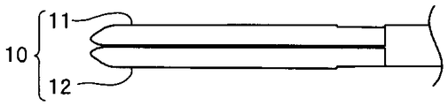
- the holding unit 10 can be opened and closed as the second holding unit 12 moves relative to the first holding unit 11. That is, as shown in FIG. 2A, when the opening / closing knob 2C is not pressed by the surgeon, the second holding portion 12 is in proximity to or in contact with the first holding portion 11 by the biasing force of an elastic member (not shown). . On the other hand, as shown in FIG. 2B, when the opening / closing knob 2C is pressed by the operator with a force stronger than the biasing force of the elastic member, the second holding portion 12 is separated from the first holding portion 11, The holding unit 10 is in an open state.
- the living tissue LT inserted between the first holding unit 11 and the second holding unit 12 is biased by the elastic member when the operator stops operating the opening / closing knob 2C.
- the holding surface 11SA of the first holding unit 11 and the holding surface 12SA of the second holding unit 12 are sandwiched and held in a pressed state.
- the heat generating substrate portion 22 is made of a nonconductor such as alumina or aluminum nitride, and a thin film resistor 23 made of a metal such as platinum is formed on the front surface. Platinum is a material with a positive resistance temperature coefficient that increases the electrical resistance R as the temperature rises. For this reason, as will be described later, the temperature of the heat generating portion 20 (thin film resistor 23) can be measured from the resistance R of the thin film resistor 23.
- the material of the thin film resistor 23 is not limited to platinum, and various positive resistance temperature coefficient refractory metal materials such as NiCr alloy, Ta, or W may be used.
- each heat generating substrate section 22 may have a plurality of thin film resistors 23.
- the second holding unit 12 may also be provided with a heat generating unit similar to the first holding unit 11, and the two heat generating units may be connected in series or in parallel.
- a metal film (not shown) is formed on the main surface (back surface) opposite to the thin film resistor forming surface of the heat generating substrate portion 22, and the metal electrode substrate 21 and a high thermal conductivity, for example, a brazing metal are used. Are joined. For this reason, the heat generated by the thin film resistor 23 is efficiently transferred to the metal electrode substrate 21 (holding surface 11SA).
- the thin film resistor forming surface (front surface) of the first holding unit 11 is covered and insulated by an insulator such as polyimide. Further, in order not to adversely affect the surrounding living tissue to be treated, it is preferable that the outer surface of the holding unit 10 is composed of a member having low thermal conductivity.
- the treatment system 1 includes the treatment tool 2, the main body 3, and the foot switch 4.
- the main body unit 3 includes a signal output unit 31, a setting unit 32, a signal detection unit 33, a control unit 34, a signal extraction unit 35, a failure detection unit 36, and a display unit 37.
- the signal output unit 31 includes a high-frequency signal oscillating unit and an amplifier for supplying a driving signal to the heat generating unit 20, that is, a power for generating heat.
- the setting unit 32 is a switch, a mouse, a keyboard, or the like that is used by the operator to set a target temperature T-set of the heat generating unit 20 or the like.
- the signal detection unit 33 is a current sensor and a voltage sensor that detect the current I and the voltage V of the drive signal.
- the signal detection unit 33 may be included in the treatment instrument 2. Further, in order to ensure electrical safety, when the drive signal output from the signal output unit 31 is an AC signal, it is transmitted to the treatment instrument 2 via, for example, a pulse transformer.
- the signal extraction unit 35 is a filter circuit that extracts a signal in a predetermined frequency band from the drive signal detected by the signal detection unit 33.
- the failure detection unit 36 detects a precursor phenomenon of failure of the heat generating unit 20 based on the extraction signal extracted by the signal extraction unit 35.
- the display unit 37 displays the temperature of the heat generating unit 20 during the treatment, displays the temperature when the operator sets the target temperature T-set by the setting unit 32, and will be described later. As described above, it also has a function of a notification unit that notifies a warning.
- the main body unit 3 may have a high-frequency signal output unit.
- the high frequency signal output from the high frequency signal output unit is applied to the pair of metal electrode substrates 21 of the treatment instrument 2.
- the surgeon can perform treatment of the living tissue LT held between the pair of holding units 10 using high-frequency energy in addition to thermal energy.
- the signal output unit having the function of the high frequency signal output unit and the function of the signal output unit 31 may alternately generate the high frequency signal and the heating drive signal.
- the surgeon uses the setting unit 32 to set the target temperature T-set of the heat generating unit 20 that is the target value at the time of treatment.
- the target temperature T-set varies depending on the living tissue LT to be treated, but is, for example, 100 ° C. to 300 ° C.
- a treatment completion time t-end or the like may be further set.
- the treatment completion time t-end is, for example, a treatment time after the target temperature T-set is reached.
- the treatment completion time t-end may be automatically set according to the impedance of the living tissue LT.
- the holding unit 10 is closed and inserted into the abdominal cavity, for example, through the abdominal wall.
- the second holding portion 12 opens with respect to the first holding portion 11.
- the biological tissue LT to be treated is disposed between the holding surface 11SA of the first holding unit 11 and the holding surface 12SA of the second holding unit 12.
- the opening / closing knob 2C is opened, the second holding unit 12 is closed with respect to the first holding unit 11 by the biasing force of the elastic member, and the living tissue LT to be treated is stored in the first holding unit 11.
- the holding surface 11SA and the holding surface 12SA of the second holding unit 12 are held in a pressed state.
- Step S13> Drive signal output In a state where the living tissue LT is held between the pair of holding portions 10, the operator presses the foot switch 4 with his / her foot. Then, the control unit 34 controls the signal output unit 31 to output a drive signal.
- the drive signal is transmitted to the heat generating unit 20 of the treatment instrument 2 via the cable 28. That is, the drive signal is applied to the thin film resistor 23 through the conductor 28 ⁇ / b> S of the cable 28, the connection board portion 20 ⁇ / b> Z of the heat generator 20, and the conductor 25, and the thin film resistor 23 generates heat.
- the heat generated by the thin film resistor 23 is transferred to the living tissue LT through the heat generating substrate portion 22 and the metal electrode substrate 21.
- the signal detection unit 33 detects the current I and the voltage V of the drive signal.
- the thin film resistor 23 is made of a material having a positive temperature coefficient of resistance, when the temperature rises, the electrical resistance R rises in proportion thereto. For this reason, the temperature of the heat generating part 20 can be acquired by calculating the resistance R from the current I and the voltage V of the drive signal and using a relational expression between the resistance and temperature stored in advance.
- a temperature sensor may be provided in the heat generating portion 20.
- the thin film resistor 23 made of a material having a positive resistance temperature coefficient the temperature of the heat generating portion 20 can be acquired with a simple configuration.
- the control unit 34 controls the signal output unit 31 to adjust the power W of the drive signal, that is, the current I and the voltage V so that the temperature of the heat generating unit 20 becomes the target temperature T-set. For this reason, as shown in FIG. 7, in the normal state, the time change of the drive signal (voltage) monotonously increases and then monotonously decreases. This is because a large amount of power is required to heat the living tissue LT from the body temperature to the target temperature T-set, but a small amount of power is sufficient to maintain the target temperature T-set.
- the signal extraction unit 35 extracts a signal (extraction signal) in a predetermined frequency band from the drive signal detected by the signal detection unit 33. That is, the signal extraction unit 35 is a band-pass filter function unit that passes signals in a predetermined frequency band and does not pass signals in other frequency bands.
- the signal extraction unit 35 includes a high pass filter and a low pass filter. This is because the low-pass filter smoothes the signal and facilitates conversion into a digital signal that can be processed by the CPU that is the control unit 34, and the high-pass filter extracts only the change that increases or decreases in a short period.
- the frequency band extracted by the signal extraction unit 35 is appropriately selected according to the characteristics of the treatment system 1.
- the range of the frequency band is, for example, preferably a lower limit of 0.1 Hz or more and an upper limit of 20 Hz or less, particularly preferably a lower limit of 1 Hz or more and an upper limit of 10 Hz or less. is there.
- a treatment signal having a heat generating unit in which a thin film resistor is connected by a conductive wire also extracts drive signals in the same frequency band as the treatment system 1.
- a precursor phenomenon of failure (disconnection) of the heat generating portion 20 could be detected.
- the precursor phenomenon is a common phenomenon in the disconnection failure of the heat generating part of the treatment system having the heat generating part to which the thin film resistor is connected by the conductive wire.
- FIG. 9 shows a normal extraction signal (voltage) in which the signal extraction unit 35 extracts a signal in the frequency band (1 Hz to 10 Hz) from the normal drive signal (voltage) shown in FIG.
- Reference numeral 10 denotes an extraction signal (voltage) from the drive signal (voltage) in which the precursor phenomenon shown in FIG. 8 occurs.
- the failure detection unit 36 detects a precursor phenomenon of failure of the heat generating unit 20 based on the extraction signal extracted by the signal extraction unit 35. For example, the failure detection unit 36 sets a sign of failure of the heat generation unit 20 when the maximum absolute value of the extracted signal is equal to or greater than a predetermined threshold (S16: Yes). For example, in the case shown in FIG. 8, the threshold voltage is set to about 40V.
- the failure detection unit 36 includes a reference voltage generation unit that generates a predetermined threshold voltage and a comparator that compares the threshold voltage and the extracted signal, and outputs the comparison result to the control unit 34 as a digital signal, for example.
- the failure detection unit 36 may use the integrated value of the extracted signal or the differential value of the extracted signal instead of the maximum value of the extracted signal in order to detect the precursor phenomenon.
- the control unit 34 controls the display unit 37, which is a notification unit, to display a warning.
- a warning sound from a speaker (not shown) may be used, or an LED (not shown) may be lit in yellow.
- the warning may be performed after one treatment is completed so as not to cause the surgeon to shake.
- the failure detection unit 36 may not only detect the precursor phenomenon but also detect a failure of the heat generating unit 20 from the drive signal. Since the electrical resistance R becomes very large when a failure of the heat generating portion 20, that is, a disconnection occurs, the detection is easy.
- the control unit 34 controls the display unit 37 serving as a notification unit to display a warning and controls the drive signal output from the signal output unit 31 to stop. . Note that an LED or the like (not shown) may be lit in red as a warning.
- Step S18> Setting Change there may be a very short time until a failure occurs after a precursor phenomenon occurs.
- the control unit 34 may decrease and control at least one of the target temperature T-set and the power W of the drive signal.
- the target temperature T-set by reducing the target temperature T-set, the time until a failure (disconnection) occurs increases, so that the treatment can be completed.
- the target temperature T-set or the power W it is preferable to automatically extend the treatment completion time t-end so that predetermined heat energy is applied to the living tissue LT to be treated. .
- step S18 is not an essential process of the treatment system 1.
- Step S19> (Treatment mode)
- the control unit 34 performs normal control. That is, the signal output unit 31 is controlled so that the process from step S13, that is, the temperature of the heat generating unit 20 becomes the target temperature T-set until the treatment completion time t-end elapses (S19: Yes). , Adjust the power of the drive signal.
- control method of the treatment system 1 includes a signal detection step for detecting the current and voltage of the drive signal, a signal extraction step for extracting a signal of a predetermined frequency band from the drive signal, and an extraction signal. And a precursor phenomenon detection step of detecting a precursor phenomenon of the failure of the heat generating portion.
- the signal extraction unit 35 extracts a signal in a predetermined frequency band from the drive signal detected by the signal detection unit 33, and the failure detection unit 36 detects a failure phenomenon of the heating unit 20 based on the extracted signal. Detect. For this reason, since it can replace
- the pair of holding portions (11A, 12A) of the treatment instrument 2 have heat generating portions 20A, 20B, respectively.
- the first heat generating unit 20A and the second heat generating unit 20B are controlled independently. That is, the signal output unit 31A outputs a drive signal A for driving the first heat generating unit 20A and a drive signal B for driving the second heat generating unit 20B.
- the signal detection unit 33A detects the current and voltage of the drive signal A and the current and voltage of the drive signal B.
- the signal extraction unit 35A extracts the extraction signals A and B from the drive signals A and B of the two heat generation units 20A and 20B, respectively. For this reason, the failure detection unit 36A independently detects the precursor phenomenon of the two heat generation units 20A and 20B.
- the probability of failure of the two heat generating parts 20A and 20B at the same time is not great.
- the control unit 34A reduces the power of the drive signal supplied to the first heat generation unit 20A, and the second heat generation. The power of the drive signal supplied to the unit 20B is increased.
- the control unit 34A reduces the power of the drive signal supplied to the second heat generating unit 20B and supplies the power to the first heat generating unit 20A. Increase the power of the drive signal.
- the control unit 34 when the precursor phenomenon is detected, for example, the control unit 34 reduces and controls at least one of the target temperature T-set and the power W of the drive signal.
- the treatment completion time t-end had to be extended so that a predetermined heat energy was applied to the tissue LT.
- the sign phenomenon is detected and the time until the occurrence of a failure (disconnection) is extended, while the treatment target living tissue LT is not treated until the set treatment completion time t-end.
- Predetermined thermal energy can be applied.
- the treatment system 1B of the third embodiment will be described. Since the treatment system 1B is similar to the treatment system 1A and the like, the same components are denoted by the same reference numerals and description thereof is omitted.
- the pair of holding portions (11A, 12A) have heating portions 20A, 20B, respectively, and the signal extraction portion 35A is a driving signal for the two heating portions 20A, 20B. From these, extraction signals A and B are extracted, respectively.
- the failure detection unit 36B detects a precursor phenomenon based on the difference between the two extracted signals A and B.
- the failure detection unit 36 compares the extracted signal with a predetermined threshold value set in advance to detect a sign of failure.
- a drive signal similar to the precursor phenomenon may be extracted depending on the treatment condition and the like.
- the probability that the two heat generating parts 20A and 20B will fail simultaneously is not great. Since the treatment system 1B detects the precursory phenomenon based on the difference between the two extracted signals A and B, even if both of the two extracted signals A and B become large due to treatment conditions or the like, it is mistaken for the precursory phenomenon. There is no judgment.
- the treatment system 1B has the effect of the treatment system 1, and further has high detection accuracy of the precursor phenomenon.
Abstract
Un système de traitement (1) est pourvu d'un élément de maintien (10) qui maintient un tissu vivant (LT), et qui a une unité de génération de chaleur (20). L'unité de génération de chaleur (20) est pourvue d'une pluralité de résistances à couche mince (23) connectées en série par câblage conducteur (25). Lorsqu'une unité de sortie de signal (31) fournit de l'énergie électrique à l'unité de génération de chaleur (20), les résistances (23) génèrent de la chaleur, et cette chaleur coagule ou dissèque le tissu vivant (LT) Une unité de détection de signal (33) détecte la tension produite par l'unité de sortie (31). Une unité d'extraction de signal (35) extrait une composante ayant une fréquence dans la plage de 1 à 10 Hz dans la tension. Si la valeur absolue maximale de cette composante atteint 40 V, une unité de détection de défaillance (36) envoie un signal à un contrôleur (34). Lorsque le contrôleur (34) reçoit ce signal, un avertissement est affiché sur un dispositif d'affichage (37). Un praticien reçoit l'avertissement à un moment dans le temps, lorsqu'un phénomène précurseur associé à une défaillance de l'unité de génération de chaleur (20) est présent dans la tension, et peut remplacer l'unité de génération de chaleur (20) en conséquence. Par conséquent, la défaillance de l'unité de génération de chaleur (20) pendant le traitement peut être évitée. En plus de la tension, le courant peut être utilisé.
Priority Applications (4)
| Application Number | Priority Date | Filing Date | Title |
|---|---|---|---|
| JP2014500179A JP5544054B2 (ja) | 2012-06-15 | 2013-06-10 | 処置システム |
| CN201380004924.2A CN104039256B (zh) | 2012-06-15 | 2013-06-10 | 处置系统 |
| EP13804265.0A EP2789306B1 (fr) | 2012-06-15 | 2013-06-10 | Système de traitement |
| US14/162,420 US9204992B2 (en) | 2012-06-15 | 2014-01-23 | Treatment system |
Applications Claiming Priority (2)
| Application Number | Priority Date | Filing Date | Title |
|---|---|---|---|
| US201261660354P | 2012-06-15 | 2012-06-15 | |
| US61/660354 | 2012-06-15 |
Related Child Applications (1)
| Application Number | Title | Priority Date | Filing Date |
|---|---|---|---|
| US14/162,420 Continuation US9204992B2 (en) | 2012-06-15 | 2014-01-23 | Treatment system |
Publications (1)
| Publication Number | Publication Date |
|---|---|
| WO2013187355A1 true WO2013187355A1 (fr) | 2013-12-19 |
Family
ID=49758177
Family Applications (1)
| Application Number | Title | Priority Date | Filing Date |
|---|---|---|---|
| PCT/JP2013/065940 WO2013187355A1 (fr) | 2012-06-15 | 2013-06-10 | Système de traitement |
Country Status (5)
| Country | Link |
|---|---|
| US (1) | US9204992B2 (fr) |
| EP (1) | EP2789306B1 (fr) |
| JP (1) | JP5544054B2 (fr) |
| CN (1) | CN104039256B (fr) |
| WO (1) | WO2013187355A1 (fr) |
Cited By (1)
| Publication number | Priority date | Publication date | Assignee | Title |
|---|---|---|---|---|
| WO2018173151A1 (fr) * | 2017-03-22 | 2018-09-27 | オリンパス株式会社 | Système de traitement |
Families Citing this family (5)
| Publication number | Priority date | Publication date | Assignee | Title |
|---|---|---|---|---|
| JP5566554B2 (ja) * | 2012-06-15 | 2014-08-06 | オリンパスメディカルシステムズ株式会社 | 処置システム |
| EP2777576B1 (fr) * | 2012-06-15 | 2019-08-07 | Olympus Corporation | Système de traitement |
| WO2016139872A1 (fr) * | 2015-03-02 | 2016-09-09 | オリンパス株式会社 | Dispositif de source d'énergie pour instrument de traitement haute fréquence, système de traitement haute fréquence, et procédé de commande pour un dispositif de source d'énergie |
| FR3046545B1 (fr) * | 2016-01-07 | 2021-05-28 | Urgo Rech Innovation Et Developpement | Dispositif de traitement dermatologique equipe d'un moyen de surveillance des ventilateurs |
| WO2018167877A1 (fr) * | 2017-03-15 | 2018-09-20 | オリンパス株式会社 | Dispositif de source d'énergie |
Citations (5)
| Publication number | Priority date | Publication date | Assignee | Title |
|---|---|---|---|---|
| JPS6434618A (en) | 1987-07-29 | 1989-02-06 | Honda Motor Co Ltd | Workpiece positioning device |
| JP2006288430A (ja) * | 2005-04-05 | 2006-10-26 | Olympus Medical Systems Corp | 発熱処置装置 |
| JP3911334B2 (ja) | 1998-01-08 | 2007-05-09 | オリンパス株式会社 | 焼灼止血装置 |
| JP2009245978A (ja) * | 2008-03-28 | 2009-10-22 | Yokogawa Electric Corp | 半導体製造装置 |
| JP2012070779A (ja) | 2010-09-27 | 2012-04-12 | Olympus Corp | 治療用処置装置 |
Family Cites Families (18)
| Publication number | Priority date | Publication date | Assignee | Title |
|---|---|---|---|---|
| JPS61128959A (ja) | 1984-11-28 | 1986-06-17 | オリンパス光学工業株式会社 | 焼灼止血装置 |
| DE3532603A1 (de) * | 1984-09-13 | 1986-03-20 | Olympus Optical Co., Ltd., Tokio/Tokyo | Kauterisations-blutstilleinrichtung |
| US5312401A (en) * | 1991-07-10 | 1994-05-17 | Electroscope, Inc. | Electrosurgical apparatus for laparoscopic and like procedures |
| US6740085B2 (en) * | 2000-11-16 | 2004-05-25 | Olympus Corporation | Heating treatment system |
| US8075558B2 (en) * | 2002-04-30 | 2011-12-13 | Surgrx, Inc. | Electrosurgical instrument and method |
| US7596469B2 (en) * | 2004-07-19 | 2009-09-29 | Baylis Medical Company Inc. | Method and apparatus for prioritizing errors in a medical treatment system |
| US7918848B2 (en) * | 2005-03-25 | 2011-04-05 | Maquet Cardiovascular, Llc | Tissue welding and cutting apparatus and method |
| US7227729B2 (en) * | 2005-09-13 | 2007-06-05 | Sensata Technologies, Inc. | Arc fault detection technique |
| US7397385B1 (en) * | 2005-12-08 | 2008-07-08 | At&T Corp. | Predicting cable failure through remote failure detection of error signatures |
| US8147485B2 (en) * | 2006-01-24 | 2012-04-03 | Covidien Ag | System and method for tissue sealing |
| US20080015575A1 (en) * | 2006-07-14 | 2008-01-17 | Sherwood Services Ag | Vessel sealing instrument with pre-heated electrodes |
| US8500728B2 (en) * | 2008-08-18 | 2013-08-06 | Encision, Inc. | Enhanced control systems including flexible shielding and support systems for electrosurgical applications |
| US8795274B2 (en) * | 2008-08-28 | 2014-08-05 | Covidien Lp | Tissue fusion jaw angle improvement |
| US8974477B2 (en) * | 2008-08-29 | 2015-03-10 | Olympus Medical Systems Corp. | Ultrasonic operating apparatus |
| US7956620B2 (en) * | 2009-08-12 | 2011-06-07 | Tyco Healthcare Group Lp | System and method for augmented impedance sensing |
| US8840609B2 (en) * | 2010-07-23 | 2014-09-23 | Conmed Corporation | Tissue fusion system and method of performing a functional verification test |
| EP2777576B1 (fr) * | 2012-06-15 | 2019-08-07 | Olympus Corporation | Système de traitement |
| JP5566554B2 (ja) * | 2012-06-15 | 2014-08-06 | オリンパスメディカルシステムズ株式会社 | 処置システム |
-
2013
- 2013-06-10 JP JP2014500179A patent/JP5544054B2/ja active Active
- 2013-06-10 WO PCT/JP2013/065940 patent/WO2013187355A1/fr active Application Filing
- 2013-06-10 CN CN201380004924.2A patent/CN104039256B/zh active Active
- 2013-06-10 EP EP13804265.0A patent/EP2789306B1/fr active Active
-
2014
- 2014-01-23 US US14/162,420 patent/US9204992B2/en active Active
Patent Citations (5)
| Publication number | Priority date | Publication date | Assignee | Title |
|---|---|---|---|---|
| JPS6434618A (en) | 1987-07-29 | 1989-02-06 | Honda Motor Co Ltd | Workpiece positioning device |
| JP3911334B2 (ja) | 1998-01-08 | 2007-05-09 | オリンパス株式会社 | 焼灼止血装置 |
| JP2006288430A (ja) * | 2005-04-05 | 2006-10-26 | Olympus Medical Systems Corp | 発熱処置装置 |
| JP2009245978A (ja) * | 2008-03-28 | 2009-10-22 | Yokogawa Electric Corp | 半導体製造装置 |
| JP2012070779A (ja) | 2010-09-27 | 2012-04-12 | Olympus Corp | 治療用処置装置 |
Non-Patent Citations (1)
| Title |
|---|
| See also references of EP2789306A4 |
Cited By (1)
| Publication number | Priority date | Publication date | Assignee | Title |
|---|---|---|---|---|
| WO2018173151A1 (fr) * | 2017-03-22 | 2018-09-27 | オリンパス株式会社 | Système de traitement |
Also Published As
| Publication number | Publication date |
|---|---|
| US20140214142A1 (en) | 2014-07-31 |
| US9204992B2 (en) | 2015-12-08 |
| JPWO2013187355A1 (ja) | 2016-02-04 |
| CN104039256A (zh) | 2014-09-10 |
| JP5544054B2 (ja) | 2014-07-09 |
| EP2789306B1 (fr) | 2019-08-07 |
| EP2789306A4 (fr) | 2015-11-04 |
| CN104039256B (zh) | 2017-02-22 |
| EP2789306A1 (fr) | 2014-10-15 |
Similar Documents
| Publication | Publication Date | Title |
|---|---|---|
| JP5544054B2 (ja) | 処置システム | |
| JP5526296B1 (ja) | 処置システム | |
| JP5566554B2 (ja) | 処置システム | |
| EP2868283B1 (fr) | Dispositif de traitement thérapeutique avec des unités de transfert de chaleur et avec des moyens de contrôle basé sur leurs températures | |
| EP3106115B1 (fr) | Systèmes pour détecter l'ouverture des mâchoires d'un joint central de scelleuse de vaisseau | |
| EP2382937B1 (fr) | Plaque de scellage à détection de pression | |
| EP1905371B1 (fr) | Système de traitement électrique | |
| CN101489499B (zh) | 电极装置 | |
| EP2575660B1 (fr) | Dispositif de suture de tissus à faible énergie | |
| US20090248021A1 (en) | End Effector Assembly for Electrosurgical Devices and System for Using the Same | |
| US20150300895A1 (en) | Contact force sensor and production method for same | |
| WO2013088893A1 (fr) | Système de traitement, et procédé de commande pour système de traitement | |
| JP5564534B2 (ja) | 中性電極インピーダンスの関数として医療装置を制御する方法 | |
| JP4734012B2 (ja) | 発熱処置装置 | |
| JP2012161565A (ja) | 治療用処置装置 | |
| CN109452967B (zh) | 一种基于反馈的热切割装置及方法 | |
| WO2018173151A1 (fr) | Système de traitement | |
| US20170319261A1 (en) | Medical treatment device | |
| JPWO2017130384A1 (ja) | 処置具及び処置システム |
Legal Events
| Date | Code | Title | Description |
|---|---|---|---|
| ENP | Entry into the national phase |
Ref document number: 2014500179 Country of ref document: JP Kind code of ref document: A |
|
| 121 | Ep: the epo has been informed by wipo that ep was designated in this application |
Ref document number: 13804265 Country of ref document: EP Kind code of ref document: A1 |
|
| WWE | Wipo information: entry into national phase |
Ref document number: 2013804265 Country of ref document: EP |
|
| NENP | Non-entry into the national phase |
Ref country code: DE |