WO2013183449A1 - 化学強化用フロートガラスの製造方法 - Google Patents
化学強化用フロートガラスの製造方法 Download PDFInfo
- Publication number
- WO2013183449A1 WO2013183449A1 PCT/JP2013/064193 JP2013064193W WO2013183449A1 WO 2013183449 A1 WO2013183449 A1 WO 2013183449A1 JP 2013064193 W JP2013064193 W JP 2013064193W WO 2013183449 A1 WO2013183449 A1 WO 2013183449A1
- Authority
- WO
- WIPO (PCT)
- Prior art keywords
- glass
- molten
- chemical strengthening
- molten metal
- float
- Prior art date
- Legal status (The legal status is an assumption and is not a legal conclusion. Google has not performed a legal analysis and makes no representation as to the accuracy of the status listed.)
- Ceased
Links
Images


Classifications
-
- C—CHEMISTRY; METALLURGY
- C03—GLASS; MINERAL OR SLAG WOOL
- C03B—MANUFACTURE, SHAPING, OR SUPPLEMENTARY PROCESSES
- C03B18/00—Shaping glass in contact with the surface of a liquid
- C03B18/02—Forming sheets
-
- C—CHEMISTRY; METALLURGY
- C03—GLASS; MINERAL OR SLAG WOOL
- C03B—MANUFACTURE, SHAPING, OR SUPPLEMENTARY PROCESSES
- C03B18/00—Shaping glass in contact with the surface of a liquid
- C03B18/02—Forming sheets
- C03B18/04—Changing or regulating the dimensions of the molten glass ribbon
- C03B18/06—Changing or regulating the dimensions of the molten glass ribbon using mechanical means, e.g. restrictor bars, edge rollers
-
- C—CHEMISTRY; METALLURGY
- C03—GLASS; MINERAL OR SLAG WOOL
- C03C—CHEMICAL COMPOSITION OF GLASSES, GLAZES OR VITREOUS ENAMELS; SURFACE TREATMENT OF GLASS; SURFACE TREATMENT OF FIBRES OR FILAMENTS MADE FROM GLASS, MINERALS OR SLAGS; JOINING GLASS TO GLASS OR OTHER MATERIALS
- C03C3/00—Glass compositions
- C03C3/04—Glass compositions containing silica
- C03C3/076—Glass compositions containing silica with 40% to 90% silica, by weight
- C03C3/078—Glass compositions containing silica with 40% to 90% silica, by weight containing an oxide of a divalent metal, e.g. an oxide of zinc
-
- C—CHEMISTRY; METALLURGY
- C03—GLASS; MINERAL OR SLAG WOOL
- C03C—CHEMICAL COMPOSITION OF GLASSES, GLAZES OR VITREOUS ENAMELS; SURFACE TREATMENT OF GLASS; SURFACE TREATMENT OF FIBRES OR FILAMENTS MADE FROM GLASS, MINERALS OR SLAGS; JOINING GLASS TO GLASS OR OTHER MATERIALS
- C03C3/00—Glass compositions
- C03C3/04—Glass compositions containing silica
- C03C3/076—Glass compositions containing silica with 40% to 90% silica, by weight
- C03C3/083—Glass compositions containing silica with 40% to 90% silica, by weight containing aluminium oxide or an iron compound
- C03C3/085—Glass compositions containing silica with 40% to 90% silica, by weight containing aluminium oxide or an iron compound containing an oxide of a divalent metal
-
- C—CHEMISTRY; METALLURGY
- C03—GLASS; MINERAL OR SLAG WOOL
- C03C—CHEMICAL COMPOSITION OF GLASSES, GLAZES OR VITREOUS ENAMELS; SURFACE TREATMENT OF GLASS; SURFACE TREATMENT OF FIBRES OR FILAMENTS MADE FROM GLASS, MINERALS OR SLAGS; JOINING GLASS TO GLASS OR OTHER MATERIALS
- C03C3/00—Glass compositions
- C03C3/04—Glass compositions containing silica
- C03C3/076—Glass compositions containing silica with 40% to 90% silica, by weight
- C03C3/083—Glass compositions containing silica with 40% to 90% silica, by weight containing aluminium oxide or an iron compound
- C03C3/085—Glass compositions containing silica with 40% to 90% silica, by weight containing aluminium oxide or an iron compound containing an oxide of a divalent metal
- C03C3/087—Glass compositions containing silica with 40% to 90% silica, by weight containing aluminium oxide or an iron compound containing an oxide of a divalent metal containing calcium oxide, e.g. common sheet or container glass
-
- Y—GENERAL TAGGING OF NEW TECHNOLOGICAL DEVELOPMENTS; GENERAL TAGGING OF CROSS-SECTIONAL TECHNOLOGIES SPANNING OVER SEVERAL SECTIONS OF THE IPC; TECHNICAL SUBJECTS COVERED BY FORMER USPC CROSS-REFERENCE ART COLLECTIONS [XRACs] AND DIGESTS
- Y02—TECHNOLOGIES OR APPLICATIONS FOR MITIGATION OR ADAPTATION AGAINST CLIMATE CHANGE
- Y02P—CLIMATE CHANGE MITIGATION TECHNOLOGIES IN THE PRODUCTION OR PROCESSING OF GOODS
- Y02P40/00—Technologies relating to the processing of minerals
- Y02P40/50—Glass production, e.g. reusing waste heat during processing or shaping
- Y02P40/57—Improving the yield, e-g- reduction of reject rates
Definitions
- the present invention relates to a method for producing float glass for chemical strengthening.
- a thin plate-like cover glass is formed on the front surface of the display so as to be wider than the image display portion in order to enhance the protection and aesthetics of the display. It has been done to arrange.
- Such a flat panel display device is required to be lightweight and thin. Therefore, the cover glass used for display protection is also required to be thin.
- the float glass manufactured by the float process is chemically strengthened to form a compressive stress layer on the surface, thereby improving the scratch resistance of the cover glass.
- the surface compressive stress of chemically strengthened float glass obtained by chemically strengthening conventional soda lime glass was about 500 MPa, and the depth of the compressive stress layer was about 10 ⁇ m.
- chemically strengthened float glass having a surface compressive stress of 600 MPa or more and a depth of the compressive stress layer of 15 ⁇ m or more has been developed.
- Patent Document 1 It has been reported that the float glass is warped after chemical strengthening and the flatness is impaired (Patent Document 1).
- the warpage is chemically strengthened between a glass surface that is not in contact with molten tin (hereinafter also referred to as a top surface) and a glass surface that is in contact with molten tin (hereinafter also referred to as a bottom surface) during float forming. This is caused by the difference in how to enter.
- the warp of the float glass increases as the way of chemical strengthening increases. Therefore, in the chemically strengthened float glass whose surface compressive stress developed to meet the demand for high scratch resistance is 600 MPa or more and the depth of the compressive stress layer is 15 ⁇ m or more, the conventional surface compressive stress is about 500 MPa. Compared with chemically strengthened float glass whose compressive stress layer has a depth of about 10 ⁇ m, the problem of warpage becomes more obvious.
- warping is caused by chemical strengthening after immersion or contact with Li ions or Na ions or a mixed inorganic salt thereof without polishing the surface of a plate-like body manufactured and processed by a float process. Improvements are disclosed.
- Patent Document 1 it is necessary to immerse the float glass in the mixed inorganic salt before chemical strengthening, which is complicated. Moreover, there is a possibility that the strength of the float glass after chemical strengthening becomes insufficient by the method of reducing the strengthening stress.
- the method of grinding or polishing the top and bottom surfaces of the float glass before chemical strengthening has a problem from the viewpoint of improving productivity, and it is preferable to omit these grinding or polishing treatments. .
- this invention provides the manufacturing method of the float glass for chemical strengthening which can suppress the curvature after chemical strengthening effectively, and can abbreviate
- the main reason for the difference in entering the chemical strengthening between the bottom surface and the top surface of the float glass is not the metal that has entered the glass surface that contacts the molten metal during the float molding, but the top surface and the bottom. It was found that this was a difference in OH concentration from the surface. Furthermore, it has been found that the amount of OH escape from the molten glass is maximized between the upstream end of the molten metal bath and the downstream of 9.1 m.
- the present inventors reduced the OH concentration difference between the top surface and the bottom surface by optimizing the float operation between the upstream end of the molten metal bath and the downstream of 9.1 m, and after chemical strengthening It has been found that warpage of float glass can be reduced. And based on these knowledge, this invention was completed.
- the present invention is as follows. (1) Pour molten glass into molten metal bath, A method for producing float glass for chemical strengthening, wherein the molten glass is formed into a plate shape while being advanced and cooled on the bath surface of the molten metal bath, The viscosity of the molten glass flowing into the molten metal bath is ⁇ 0, When the viscosity of the molten glass 9.1 m downstream from the upstream end of the molten metal bath is ⁇ 1, ⁇ 1- ⁇ 0 ⁇ 2.0 ⁇ 10 4 (Pa ⁇ s) The manufacturing method of the float glass for chemical strengthening which is.
- the viscosity of the molten glass is 2.0 ⁇ between the upstream end of the molten metal bath, which is the region where the amount of OH escape from the molten glass is the largest, and 9.1 m downstream. Increased by 10 4 (Pa ⁇ s) or more. That is, since the temperature of the molten glass is decreased by a predetermined value or more in the above region, diffusion of OH from the molten glass can be suppressed, and an increase in OH concentration difference between the top surface and the bottom surface can be suppressed. Therefore, the float glass for chemical strengthening of the present invention reduces the warp of the float glass after chemical strengthening without reducing the stress due to chemical strengthening and even if the polishing treatment before chemical strengthening is simplified or omitted. Excellent flatness can be obtained.
- the molten glass when a float glass for chemical strengthening is produced using a molten glass having a viscosity of 2.5 ⁇ 10 4 Pa ⁇ s at 850 to 1100 ° C., the molten glass
- the temperature of the molten glass was decreased by 200 ° C. or more between the upstream end of the molten metal bath, which is the region where the amount of OH escape from the largest was 9.1 m downstream.
- diffusion of OH from the molten glass can be suppressed, and an increase in the OH concentration difference between the top surface and the bottom surface can be suppressed. Therefore, it is possible to reduce the warp of the float glass after chemical strengthening.
- the residence time of the molten glass is shortened from the upstream end of the molten metal bath, which is the region where the amount of OH escape from the molten glass is the largest, to 9.1 m downstream.
- the rotational speed S of the top roll located in the uppermost stream was set so as to satisfy 9.1 / S ⁇ 20 (min).
- FIG. 6 is a graph showing a relationship between an increase amount of viscosity ⁇ 1- ⁇ 0 and a ⁇ warpage conversion value. 6 is a graph showing a relationship between a temperature decrease amount T0-T1 and a ⁇ warpage amount converted value. It is a graph which shows the relationship between the rotational speed S of a pair of top roll located in the most upstream, and (DELTA) curvature amount conversion value.
- the float glass for chemical strengthening of the present invention is formed by a float process, and has a bottom surface that is in contact with the molten metal at the time of forming, and a top surface that faces the bottom surface.
- the present inventors have found that the main cause of warpage caused by chemically strengthening the float glass is a difference in OH concentration between the top surface and the bottom surface, as will be described below.
- molten glass is continuously supplied from the upstream side to the surface of the molten metal stored in the float bath to form a glass ribbon. And the glass ribbon after shaping
- molding is pulled out from the downstream edge part of a float bath, and plate glass is manufactured by slowly cooling with a layer.
- the float glass produced by this type of apparatus has a smaller OH concentration on the surface (5 to 10 ⁇ m) than the OH concentration inside (typically a depth of about 50 ⁇ m or more). Since the diffusion coefficient of H 2 O is higher at higher temperatures, the diffusion amount of H 2 O from the top surface in contact with an atmosphere having a lower dew point or higher temperature than the bottom surface of the float glass in contact with the lower temperature molten metal More. Therefore, the OH concentration on the top surface is lower than the bottom surface of the float glass.
- the flow path is not restricted between the glass tank kiln and the float bath.
- the lower temperature molten glass is poured into the hot molten metal and molded compared to the type of equipment described above.
- the bottom surface temperature may be higher than the top surface of the float glass. In such a case, the amount of diffusion of H 2 O from the bottom surface is larger than that of the top surface, and the OH concentration on the bottom surface is lower than that of the top surface of the float glass.
- the glass produced by the float process has a lower OH concentration on the top surface than on the bottom surface or a lower OH concentration on the bottom surface than the top surface depending on the production conditions, and the OH between the top surface and the bottom surface. A density difference occurs.
- the OH concentration on the top surface is lower than the bottom surface of the float glass will be mainly described, but the present invention is not limited to this.
- the glass surface with a high OH concentration is less stressed during chemical strengthening, and the glass surface with a lower OH concentration is susceptible to stress during chemical strengthening. It becomes.
- the stress approaches to a state where the stresses are balanced, and the warpage is reduced.
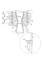
- the float glass for chemical strengthening of the present invention is manufactured by a manufacturing apparatus as shown in FIGS. 1 and 2, 12 is a twill, 22 is a fixed refractory under the twill, and 23 is a spout lip.
- the molten glass 1 is obtained by continuously supplying raw materials into a glass tank kiln and melting them in a high temperature region. Subsequently, the molten glass 1 is guided to the cooling region and the temperature is adjusted.
- the molten glass 1 passes through the gap 2 formed by the connecting groove 11 and the twill 12 and the fixed refractory 22 below the twelve 12, passes through the lip 23 of the spout, and goes to the molten metal bath 5 in the float bath 14. Inflow.
- the molten glass 1 that has flowed into the molten metal bath 5 is pressed by the top roll 30 that is a rotating roll having teeth and grooves around the both sides of the surface in the width direction, so that tension is applied in the width direction.
- the top roll 30 that is a rotating roll having teeth and grooves around the both sides of the surface in the width direction, so that tension is applied in the width direction.
- a plurality of sets of top rolls 30 are disposed on both sides of the molten glass 1 in the width direction, and the rotation shafts 32 of the paired top rolls 30 are expanded in a substantially square shape. Furthermore, each of the plurality of top rolls 30 can freely set the rotation speed, and the traveling speed of the molten glass 1 can be adjusted.
- BAY indicated by broken lines indicate the distance along the downstream side from the upstream end of the molten metal bath 5.
- One BAY is 3.048 m (about 3.0 m).
- the molten metal bath 5 is provided with a plurality of sets of top rolls 30, but the present invention is not limited to this configuration, and is 3 BAY (about 9.1 m) downstream from the upstream end of the molten metal bath 5.
- at least a pair of top rolls 30 may be provided.
- the present inventors considered the OH behavior in the thickness direction of the molten glass 1 as a one-dimensional diffusion phenomenon.
- the governing equation was constructed by assuming. And the analysis of the OH density
- OH-deficient region diffusion of OH from the molten glass 1 from the upstream end of the molten metal bath 5 to the downstream of about 9.1 m (hereinafter referred to as OH-deficient region) is caused by the difference in OH concentration between the top surface and the bottom surface, and It has been found that there is a possibility of greatly affecting the warpage of float glass after chemical strengthening.
- the conditions of the molten glass 1 such as the temperature (viscosity), the thickness, the residence time, etc. are appropriately set, thereby the float glass chemistry. Realized to reduce warping after strengthening.
- the temperature of the molten glass 1 in the OH-deficient region is greatly reduced as compared with the conventional case, that is, the viscosity of the molten glass 1 in the OH-deficient region is made higher than before. It is conceivable to suppress diffusion of OH from the molten glass 1 by increasing it greatly.
- the present invention can be applied to any molten glass 1 regardless of the composition, the viscosity of the molten glass 1 flowing into the molten metal bath 5 is ⁇ 0, and 9 from the upstream end of the molten metal bath 5 is obtained.
- the viscosity of the molten glass 1 downstream of 1 m (3 BAY) is ⁇ 1
- ⁇ 1 ⁇ 0 ⁇ 3.0 ⁇ 10 4 ( (Pa ⁇ s) is more preferable.
- a molten metal bath is used. It is preferable that T0 ⁇ T1 ⁇ 200 (° C.), where T0 is the temperature of the molten glass 1 flowing into 5 and T1 is the temperature of the molten glass 1 9.1 m downstream from the upstream end of the molten metal bath 5. More preferably, T0 ⁇ T1 ⁇ 230 (° C.).
- the traveling speed of the molten glass 1 in the OH-deficient region has a correlation with the rotational speed S of the pair of top rolls 30 located in the uppermost stream. Therefore, the residence time of the molten glass 1 in the OH-deficient region has a correlation with a value obtained by dividing the length (9.1 m) of the OH-deficient region by the rotational speed S of the pair of top rolls 30 positioned in the uppermost stream. Therefore, in the present invention, the rotational speed S is set so as to satisfy 9.1 / S ⁇ 20 (min), more preferably, 9.1 / S ⁇ 10 (min), so that the molten glass in the OH-deficient region is set. 1 stay time has been shortened.
- the shortening of the residence time of the molten glass 1 in the OH-deficient region is not limited to the adjustment of the rotational speeds of the pair of top rolls 30 located in the uppermost stream described above, but the rotational speeds of the other top rolls 30 in the OH-deficient region. It can be realized by adjusting or adjusting the position and angle at which the top roll 30 is arranged.
- the width of the molten glass 1 is not widened by narrowing the distance between the paired top rolls 30, but the line speed is increased and sent quickly to the downstream side.
- the width of the molten glass 1 may be widened by widening the interval between the top rolls 30 so that the glass ribbon 4 has a predetermined shape.
- the glass ribbon 4 formed in the float bath 14 is gradually cooled to room temperature in a slow cooling furnace (not shown), and the process of manufacturing float glass for chemical strengthening is completed through processes such as cleaning, inspection, and cutting.
- a slow cooling furnace not shown
- uneven marks are formed along the traveling direction on both sides in the width direction of the glass ribbon 4 pressed by the top roll 30, it is removed in the cutting step.
- a chemically strengthened float glass can be obtained by chemically strengthening a float glass for chemical strengthening formed into a plate shape through such a process.
- alkali metal ions typically Li ions or Na ions
- alkali ions typically, This is a process of forming a compressive stress layer on the glass surface by exchanging with K ions.
- the chemical strengthening treatment can be performed by a conventionally known method.
- board thickness for the chemically strengthened float glass manufactured by this invention is 1.5 mm or less, and it is more preferable that it is 1.1 mm or less. Moreover, although it is typically 0.7 mm or more, a thinner one is used if necessary.
- the float glass for chemical strengthening produced according to the present invention can reduce warpage after chemical strengthening regardless of the composition.
- the composition of the float glass for chemical strengthening for example, the following glass composition: Is mentioned.
- (I) a composition that is displayed in mol%, the SiO 2 50 ⁇ 80%, the Al 2 O 3 2 ⁇ 25% , the Li 2 O 0 ⁇ 10%, a Na 2 O 0 ⁇ 18%, K 2 O 0-10%, MgO 0-15%, CaO 0-5% and ZrO 2 0-5%.
- the K 2 O containing 0-10% is, K 2 O is not essential may contain up to 10% in a range that does not impair the object of the present invention, a meaning of.
- the composition expressed in mol% is SiO 2 50-74%, Al 2 O 3 1-10%, Na 2 O 6-14%, K 2 O 3-11%, MgO 2 -15%, CaO 0-6% and ZrO 2 0-5%, the total content of SiO 2 and Al 2 O 3 is 75% or less, the total content of Na 2 O and K 2 O Is 12-25%, and the total content of MgO and CaO is 7-15%.
- the composition expressed in terms of mol% of glass (iii) is composed of 68-80% of SiO 2 and 4-10% of Al 2 O 3.
- composition expressed as glass (iv) mol% containing 5 to 15% Na 2 O, 0 to 1% K 2 O, 4 to 15% MgO and 0 to 1% ZrO 2 is SiO 2 67-75%, Al 2 O 3 0-4%, Na 2 O 7-15%, K 2 O 1-9%, 6 to 14% MgO and 0 to 1.5% ZrO 2 , the total content of SiO 2 and Al 2 O 3 is 71 to 75%, the total content of Na 2 O and K 2 O is Glass containing 12 to 20% and containing CaO when the content is less than 1%
- the amount of warpage of the float glass can be measured with a three-dimensional shape measuring instrument (for example, manufactured by Mitaka Kogyo Co., Ltd.). Specifically, the difference between the highest point and the lowest point is obtained at several places in the width direction of the float glass, and obtained based on the average value of these differences.
- the change in the amount of warp of the float glass before and after chemical strengthening can be measured by the ⁇ warp amount [(warp amount after chemical strengthening) ⁇ (warp amount before chemical strengthening)].
- the ⁇ warpage amount converted value when measured using a 100 mm square float glass and converted to a plate thickness of 0.8 mm is preferably 100 ⁇ m or less.
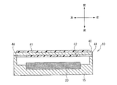
- FIG. 3 is a cross-sectional view of a display device in which a cover glass is disposed.
- front, rear, left and right are based on the direction of the arrow in the figure.
- the display device 10 includes a display panel 20 provided in the housing 15 and a cover glass 40 that covers the entire surface of the display panel 20 and surrounds the front of the housing 15.
- the cover glass 40 is installed mainly for the purpose of improving the aesthetics and strength of the display device 10 and preventing impact damage, and is formed of a single plate-like glass having an overall planar shape.
- the cover glass 40 may be installed so as to be separated from the display side (front side) of the display panel 20 (having an air layer), and is displayed via a translucent adhesive film (not shown). You may affix on the display side of the panel 20.
- FIG. 1 is mainly for the purpose of improving the aesthetics and strength of the display device 10 and preventing impact damage, and is formed of a single plate-like glass having an overall planar shape.
- the cover glass 40 may be installed so as to be separated from the display side (front side) of the display panel 20 (having an air layer), and is displayed via a translucent adhesive film (not shown). You may affix on the display side of the panel 20.
- a functional film 41 is provided on the front surface of the cover glass 40 that emits light from the display panel 20.
- a functional film 42 is provided at a position corresponding to the display panel 20 on the back surface on which light from the display panel 20 is incident.
- the functional films 41 and 42 are provided on both surfaces in FIG. 3, the functional films 41 and 42 are not limited to this and may be provided on the front surface or the back surface, or may be omitted.
- the functional films 41 and 42 have functions such as anti-reflection of ambient light, prevention of impact breakage, electromagnetic wave shielding, near-infrared shielding, color tone correction, and / or scratch resistance improvement, and thickness and shape are used for applications. It is selected as appropriate.
- the functional films 41 and 42 are formed, for example, by attaching a resin film to the cover glass 40. Or you may form by thin film formation methods, such as a vapor deposition method, a sputtering method, or CVD method.
- Reference numeral 44 denotes a black layer, which is, for example, a coating formed by applying ink containing pigment particles to the cover glass 40, irradiating it with ultraviolet rays, or baking it, followed by cooling.
- a black layer which is, for example, a coating formed by applying ink containing pigment particles to the cover glass 40, irradiating it with ultraviolet rays, or baking it, followed by cooling.
- the float glass for chemical strengthening having the following composition was manufactured by the above-described manufacturing method in two lines (line I and line II) having different conditions such as the length of the float bath 14.
- SiO 2 is 64.2%
- Al 2 O 3 is 8.0%
- MgO is 10.5%
- CaO is 0.1%
- SrO is 0.1%
- BaO is 0.1%.
- the glass has a viscosity of about 2.5 ⁇ 10 4 Pa ⁇ s.
- the temperature is about 1010 ° C.
- the temperature T0 of the molten glass 1 flowing into the molten metal bath 5 and the temperature T1 of the molten glass 1 9.1 m downstream from the upstream end of the molten metal bath 5 are measured, and the viscosity ⁇ 0 at these positions, ⁇ 1 was determined.
- the temperature T0 of the molten glass 1 flowing into the molten metal bath 5 is a value measured by bringing a thermocouple into contact with the glass substrate in the connection groove 11.
- the temperature T1 of the molten glass 1 9.1 m downstream from the upstream end of the molten metal bath 5 is, for Line I, two values measured with a radiation thermometer in the 2 to 3 BAY intermediate part and the 4 to 5 BAY intermediate part. This is a value derived by interpolation, and line II is a value derived by interpolating two values measured with a radiation thermometer at the 2 to 3 BAY intermediate part and the 5 to 6 BAY intermediate part.
- the ⁇ warp amount is inversely proportional to the square of the plate thickness. Therefore, to eliminate the influence of the plate thickness, the ⁇ warp amount is converted to the ⁇ warp amount by the following calculation formula when the plate thickness is 0.8 mm. Calculated as value.
- ⁇ warpage amount conversion value ⁇ warpage amount ⁇ (sheet thickness) 2 ⁇ 0.8 2
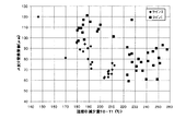
- FIG. 4 shows the increase in the viscosity ⁇ 1- ⁇ 0 (Pa ⁇ s) of the molten glass 1 in the OH-deficient region and the ⁇ warpage amount conversion value ( ⁇ m) for the float glass produced in the lines I and II.
- the relationship was shown. It can be seen that in line I and line II, the ⁇ warpage amount converted value decreases as the increase in viscosity ⁇ 1- ⁇ 0 in the OH-deficient region increases. This is because diffusion of OH from the molten glass 1 is suppressed as the increase in viscosity ⁇ 1- ⁇ 0 in the OH-deficient region increases, that is, as the decrease in temperature T0-T1 in the OH-deficient region increases.
- FIG. 5 shows the relationship between the decrease amount T0-T1 (° C.) of the temperature of the molten glass 1 in the OH-deficient region and the ⁇ warpage amount conversion value ( ⁇ m) for the float glass manufactured in the lines I and II. Indicated. For the same reason as described above, it can be seen that in both the lines I and II, the ⁇ warpage amount converted value decreases as the temperature decrease amount T0-T1 in the OH-deficient region increases.
- the ⁇ warpage conversion value is 100 ( ⁇ m) or less, and chemical strengthening It became clear that later warping was effectively suppressed.
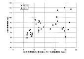
- FIG. 6 shows the length (9.1 m) of the OH-deficient region when the rotational speed S of the pair of top rolls 30 positioned in the uppermost stream is changed when manufacturing the float glass in the lines I and II.
- 9.1 / S (min) which is a value divided by the rotational speed S of the pair of top rolls 30 positioned in the uppermost stream
- ⁇ warpage amount converted value ⁇ m
- the ⁇ warpage amount converted value is 100 ( ⁇ m) or less, and in the range of 9.1 / S ⁇ 10 (min), in all the samples.
- the ⁇ warpage amount converted value was 80 ( ⁇ m) or less, and it became clear that the warpage after chemical strengthening was effectively suppressed.
Landscapes
- Chemical & Material Sciences (AREA)
- Engineering & Computer Science (AREA)
- Materials Engineering (AREA)
- Organic Chemistry (AREA)
- Life Sciences & Earth Sciences (AREA)
- Chemical Kinetics & Catalysis (AREA)
- General Chemical & Material Sciences (AREA)
- Geochemistry & Mineralogy (AREA)
- Mechanical Engineering (AREA)
- Surface Treatment Of Glass (AREA)
- Liquid Crystal (AREA)
- Glass Compositions (AREA)
Abstract
Description
(1) 溶融ガラスを溶融金属浴に流入させ、
前記溶融ガラスを前記溶融金属浴の浴面上を前進させて冷却しながら板状に成形する化学強化用フロートガラスの製造方法であって、
前記溶融金属浴へ流入する前記溶融ガラスの粘度をη0とし、
前記溶融金属浴の上流端から9.1m下流の前記溶融ガラスの粘度をη1としたとき、
η1-η0≧2.0×10⁴(Pa・s)
である化学強化用フロートガラスの製造方法。
(2) 粘度が2.5×10⁴Pa・sとなる温度が850~1100℃であるガラスの溶融ガラスを溶融金属浴に流入させ、
前記溶融ガラスを前記溶融金属浴の浴面上を前進させて冷却しながら板状に成形する化学強化用フロートガラスの製造方法であって、
前記溶融金属浴へ流入する前記溶融ガラスの温度をT0とし、
前記溶融金属浴の上流端から9.1m下流の前記溶融ガラスの温度をT1としたとき、
T0-T1≧200(℃)
である化学強化用フロートガラスの製造方法。
(3) 溶融ガラスを溶融金属浴に流入させ、
前記溶融ガラスを前記溶融金属浴の浴面上を前進させて冷却しながら板状に成形する化学強化用フロートガラスの製造方法であって、
前記溶融金属浴の上流端から9.1m下流までの間には、前記溶融ガラスの表面の両側部を押圧するトップロールが少なくとも一対設けられ、
最上流に位置する前記一対のトップロールの回転速度をS(m/min)としたとき、
9.1/S≦20(min)
である化学強化用フロートガラスの製造方法。
以上説明したような知見に基づき、本発明者らは、フロートガラスにおけるトップ面とボトム面とのOH濃度差を小さくすることによって、化学強化後の反りを低減することが可能な、化学強化用フロートガラスの製造方法を発明した。
(i)モル%で表示した組成で、SiO2を50~80%、Al2O3を2~25%、Li2Oを0~10%、Na2Oを0~18%、K2Oを0~10%、MgOを0~15%、CaOを0~5%およびZrO2を0~5%を含むガラス。ここで、例えば「K2Oを0~10%含有する」とは、K2Oは必須ではないが本発明の目的を損なわない範囲で10%まで含有してよい、の意である。
(ii)モル%で表示した組成が、SiO2を50~74%、Al2O3を1~10%、Na2Oを6~14%、K2Oを3~11%、MgOを2~15%、CaOを0~6%およびZrO2を0~5%含有し、SiO2およびAl2O3の含有量の合計が75%以下、Na2OおよびK2Oの含有量の合計が12~25%、MgOおよびCaOの含有量の合計が7~15%であるガラス
(iii)モル%で表示した組成が、SiO2を68~80%、Al2O3を4~10%、Na2Oを5~15%、K2Oを0~1%、MgOを4~15%およびZrO2を0~1%含有するガラス(iv)モル%で表示した組成が、SiO2を67~75%、Al2O3を0~4%、Na2Oを7~15%、K2Oを1~9%、MgOを6~14%およびZrO2を0~1.5%含有し、SiO2およびAl2O3の含有量の合計が71~75%、Na2OおよびK2Oの含有量の合計が12~20%であり、CaOを含有する場合その含有量が1%未満であるガラス
モル%表示で、SiO2を64.2%、Al2O3を8.0%、MgOを10.5%、CaOが0.1%、SrOを0.1%、BaOを0.1%、Na2Oを12.5%、K2Oを4.0%、ZrO2を0.5%含有するガラス
ここで、当該ガラスは、粘度が約2.5×10⁴Pa・sとなる温度が約1010℃である。
Δ反り量換算値=Δ反り量×(板厚)2÷0.82
2 間隙
4 ガラスリボン
5 溶融金属浴
10 ディスプレイ装置
11 接続溝
12 ツイール
14 フロートバス
15 筐体
20 表示パネル
22 固定耐火物
23 リップ
30 トップロール
32 回転軸
40 カバーガラス
41、42 機能膜
44 黒色層
Claims (3)
- 溶融ガラスを溶融金属浴に流入させ、
前記溶融ガラスを前記溶融金属浴の浴面上を前進させて冷却しながら板状に成形する化学強化用フロートガラスの製造方法であって、
前記溶融金属浴へ流入する前記溶融ガラスの粘度をη0とし、
前記溶融金属浴の上流端から9.1m下流の前記溶融ガラスの粘度をη1としたとき、
η1-η0≧2.0×10⁴(Pa・s)
である化学強化用フロートガラスの製造方法。 - 粘度が2.5×10⁴Pa・sとなる温度が850~1100℃であるガラスの溶融ガラスを溶融金属浴に流入させ、
前記溶融ガラスを前記溶融金属浴の浴面上を前進させて冷却しながら板状に成形する化学強化用フロートガラスの製造方法であって、
前記溶融金属浴へ流入する前記溶融ガラスの温度をT0とし、
前記溶融金属浴の上流端から9.1m下流の前記溶融ガラスの温度をT1としたとき、
T0-T1≧200(℃)
である化学強化用フロートガラスの製造方法。 - 溶融ガラスを溶融金属浴に流入させ、
前記溶融ガラスを前記溶融金属浴の浴面上を前進させて冷却しながら板状に成形する化学強化用フロートガラスの製造方法であって、
前記溶融金属浴の上流端から9.1m下流までの間には、前記溶融ガラスの表面の両側部を押圧するトップロールが少なくとも一対設けられ、
最上流に位置する前記一対のトップロールの回転速度をS(m/min)としたとき、
9.1/S≦20(min)
である化学強化用フロートガラスの製造方法。
Priority Applications (3)
| Application Number | Priority Date | Filing Date | Title |
|---|---|---|---|
| KR20147034145A KR20150022805A (ko) | 2012-06-04 | 2013-05-22 | 화학 강화용 플로트 유리의 제조 방법 |
| JP2014519917A JP6065006B2 (ja) | 2012-06-04 | 2013-05-22 | 化学強化用フロートガラスの製造方法 |
| CN201380029604.2A CN104364206B (zh) | 2012-06-04 | 2013-05-22 | 化学强化用浮法玻璃的制造方法 |
Applications Claiming Priority (2)
| Application Number | Priority Date | Filing Date | Title |
|---|---|---|---|
| JP2012-127396 | 2012-06-04 | ||
| JP2012127396 | 2012-06-04 |
Publications (1)
| Publication Number | Publication Date |
|---|---|
| WO2013183449A1 true WO2013183449A1 (ja) | 2013-12-12 |
Family
ID=49711847
Family Applications (1)
| Application Number | Title | Priority Date | Filing Date |
|---|---|---|---|
| PCT/JP2013/064193 Ceased WO2013183449A1 (ja) | 2012-06-04 | 2013-05-22 | 化学強化用フロートガラスの製造方法 |
Country Status (4)
| Country | Link |
|---|---|
| JP (1) | JP6065006B2 (ja) |
| KR (1) | KR20150022805A (ja) |
| TW (1) | TW201406674A (ja) |
| WO (1) | WO2013183449A1 (ja) |
Cited By (1)
| Publication number | Priority date | Publication date | Assignee | Title |
|---|---|---|---|---|
| JP2020514219A (ja) * | 2016-12-22 | 2020-05-21 | ショット アクチエンゲゼルシャフトSchott AG | 薄板ガラス基板、その製造方法および製造装置 |
Citations (4)
| Publication number | Priority date | Publication date | Assignee | Title |
|---|---|---|---|---|
| JP2000281365A (ja) * | 1999-04-01 | 2000-10-10 | Nippon Sheet Glass Co Ltd | フロート式板ガラス製造方法及びその製造装置 |
| JP2008143746A (ja) * | 2006-12-11 | 2008-06-26 | Nippon Electric Glass Co Ltd | ガラス板の製造方法及びその装置並びにフラットパネルディスプレイ用ガラス基板 |
| JP2010168252A (ja) * | 2009-01-23 | 2010-08-05 | Nippon Electric Glass Co Ltd | 強化ガラスの製造方法 |
| WO2013005588A1 (ja) * | 2011-07-01 | 2013-01-10 | 旭硝子株式会社 | 化学強化用フロートガラス |
-
2013
- 2013-05-22 KR KR20147034145A patent/KR20150022805A/ko not_active Withdrawn
- 2013-05-22 JP JP2014519917A patent/JP6065006B2/ja active Active
- 2013-05-22 WO PCT/JP2013/064193 patent/WO2013183449A1/ja not_active Ceased
- 2013-06-04 TW TW102119833A patent/TW201406674A/zh unknown
Patent Citations (4)
| Publication number | Priority date | Publication date | Assignee | Title |
|---|---|---|---|---|
| JP2000281365A (ja) * | 1999-04-01 | 2000-10-10 | Nippon Sheet Glass Co Ltd | フロート式板ガラス製造方法及びその製造装置 |
| JP2008143746A (ja) * | 2006-12-11 | 2008-06-26 | Nippon Electric Glass Co Ltd | ガラス板の製造方法及びその装置並びにフラットパネルディスプレイ用ガラス基板 |
| JP2010168252A (ja) * | 2009-01-23 | 2010-08-05 | Nippon Electric Glass Co Ltd | 強化ガラスの製造方法 |
| WO2013005588A1 (ja) * | 2011-07-01 | 2013-01-10 | 旭硝子株式会社 | 化学強化用フロートガラス |
Cited By (8)
| Publication number | Priority date | Publication date | Assignee | Title |
|---|---|---|---|---|
| JP2020514219A (ja) * | 2016-12-22 | 2020-05-21 | ショット アクチエンゲゼルシャフトSchott AG | 薄板ガラス基板、その製造方法および製造装置 |
| JP7208141B2 (ja) | 2016-12-22 | 2023-01-18 | ショット アクチエンゲゼルシャフト | 薄板ガラス基板、その製造方法および製造装置 |
| JP2023036947A (ja) * | 2016-12-22 | 2023-03-14 | ショット アクチエンゲゼルシャフト | 薄板ガラス基板、その製造方法および製造装置 |
| US11745459B2 (en) * | 2016-12-22 | 2023-09-05 | Schott Ag | Thin glass substrate, in particular a borosilicate glass thin glass substrate, method and apparatus for its production |
| US11890844B2 (en) * | 2016-12-22 | 2024-02-06 | Schott Ag | Thin glass substrate, method and apparatus for its production |
| US11993062B2 (en) | 2016-12-22 | 2024-05-28 | Schott Ag | Composite glass pane |
| US12005687B2 (en) | 2016-12-22 | 2024-06-11 | Schott Ag | Thin glass substrate, method and apparatus for its production |
| JP7505053B2 (ja) | 2016-12-22 | 2024-06-24 | ショット アクチエンゲゼルシャフト | 薄板ガラス基板、その製造方法および製造装置 |
Also Published As
| Publication number | Publication date |
|---|---|
| KR20150022805A (ko) | 2015-03-04 |
| CN104364206A (zh) | 2015-02-18 |
| JP6065006B2 (ja) | 2017-01-25 |
| TW201406674A (zh) | 2014-02-16 |
| JPWO2013183449A1 (ja) | 2016-01-28 |
Similar Documents
| Publication | Publication Date | Title |
|---|---|---|
| JP5929999B2 (ja) | 化学強化用フロートガラス | |
| JP6112122B2 (ja) | 化学強化用フロートガラス | |
| JPWO2013005608A1 (ja) | 化学強化用フロートガラス | |
| WO2014200097A1 (ja) | 化学強化処理によるガラス基板の反りを低減する方法、化学強化ガラス及びその製造方法 | |
| WO2013099620A1 (ja) | 化学強化処理によるガラス基板の反りを低減する方法、および化学強化ガラス基板の製造方法 | |
| WO2015156262A1 (ja) | 化学強化ガラスの製造方法 | |
| JP6065006B2 (ja) | 化学強化用フロートガラスの製造方法 | |
| CN104364206B (zh) | 化学强化用浮法玻璃的制造方法 | |
| TW201514119A (zh) | 玻璃板 | |
| TW201311596A (zh) | 附有積層膜之玻璃基板之製造方法 | |
| WO2014112482A1 (ja) | 積層膜付きガラス基板及びその製造方法 | |
| JP2013006749A (ja) | 化学強化用フロートガラス | |
| WO2025142925A1 (ja) | ガラス板及びガラス板の製造方法 | |
| TW201514104A (zh) | 浮式玻璃之製造方法 |
Legal Events
| Date | Code | Title | Description |
|---|---|---|---|
| 121 | Ep: the epo has been informed by wipo that ep was designated in this application |
Ref document number: 13799991 Country of ref document: EP Kind code of ref document: A1 |
|
| ENP | Entry into the national phase |
Ref document number: 2014519917 Country of ref document: JP Kind code of ref document: A |
|
| ENP | Entry into the national phase |
Ref document number: 20147034145 Country of ref document: KR Kind code of ref document: A |
|
| NENP | Non-entry into the national phase |
Ref country code: DE |
|
| 122 | Ep: pct application non-entry in european phase |
Ref document number: 13799991 Country of ref document: EP Kind code of ref document: A1 |