WO2013180282A1 - 車両用暖房装置 - Google Patents
車両用暖房装置 Download PDFInfo
- Publication number
- WO2013180282A1 WO2013180282A1 PCT/JP2013/065224 JP2013065224W WO2013180282A1 WO 2013180282 A1 WO2013180282 A1 WO 2013180282A1 JP 2013065224 W JP2013065224 W JP 2013065224W WO 2013180282 A1 WO2013180282 A1 WO 2013180282A1
- Authority
- WO
- WIPO (PCT)
- Prior art keywords
- flow path
- fluid
- heat exchange
- cooling water
- exhaust
- Prior art date
- Legal status (The legal status is an assumption and is not a legal conclusion. Google has not performed a legal analysis and makes no representation as to the accuracy of the status listed.)
- Ceased
Links
Images



Classifications
-
- F—MECHANICAL ENGINEERING; LIGHTING; HEATING; WEAPONS; BLASTING
- F01—MACHINES OR ENGINES IN GENERAL; ENGINE PLANTS IN GENERAL; STEAM ENGINES
- F01N—GAS-FLOW SILENCERS OR EXHAUST APPARATUS FOR MACHINES OR ENGINES IN GENERAL; GAS-FLOW SILENCERS OR EXHAUST APPARATUS FOR INTERNAL-COMBUSTION ENGINES
- F01N5/00—Exhaust or silencing apparatus combined or associated with devices profiting by exhaust energy
- F01N5/02—Exhaust or silencing apparatus combined or associated with devices profiting by exhaust energy the devices using heat
-
- B—PERFORMING OPERATIONS; TRANSPORTING
- B60—VEHICLES IN GENERAL
- B60H—ARRANGEMENTS OF HEATING, COOLING, VENTILATING OR OTHER AIR-TREATING DEVICES SPECIALLY ADAPTED FOR PASSENGER OR GOODS SPACES OF VEHICLES
- B60H1/00—Heating, cooling or ventilating devices
- B60H1/02—Heating, cooling or ventilating devices the heat being derived from the propulsion plant
- B60H1/14—Heating, cooling or ventilating devices the heat being derived from the propulsion plant other than from cooling liquid of the plant
- B60H1/18—Heating, cooling or ventilating devices the heat being derived from the propulsion plant other than from cooling liquid of the plant the air being heated from the plant exhaust gases
- B60H1/20—Heating, cooling or ventilating devices the heat being derived from the propulsion plant other than from cooling liquid of the plant the air being heated from the plant exhaust gases using an intermediate heat-transferring medium
-
- F—MECHANICAL ENGINEERING; LIGHTING; HEATING; WEAPONS; BLASTING
- F01—MACHINES OR ENGINES IN GENERAL; ENGINE PLANTS IN GENERAL; STEAM ENGINES
- F01N—GAS-FLOW SILENCERS OR EXHAUST APPARATUS FOR MACHINES OR ENGINES IN GENERAL; GAS-FLOW SILENCERS OR EXHAUST APPARATUS FOR INTERNAL-COMBUSTION ENGINES
- F01N3/00—Exhaust or silencing apparatus having means for purifying, rendering innocuous, or otherwise treating exhaust
- F01N3/02—Exhaust or silencing apparatus having means for purifying, rendering innocuous, or otherwise treating exhaust for cooling, or for removing solid constituents of, exhaust
- F01N3/0205—Exhaust or silencing apparatus having means for purifying, rendering innocuous, or otherwise treating exhaust for cooling, or for removing solid constituents of, exhaust using heat exchangers
-
- F—MECHANICAL ENGINEERING; LIGHTING; HEATING; WEAPONS; BLASTING
- F01—MACHINES OR ENGINES IN GENERAL; ENGINE PLANTS IN GENERAL; STEAM ENGINES
- F01N—GAS-FLOW SILENCERS OR EXHAUST APPARATUS FOR MACHINES OR ENGINES IN GENERAL; GAS-FLOW SILENCERS OR EXHAUST APPARATUS FOR INTERNAL-COMBUSTION ENGINES
- F01N2240/00—Combination or association of two or more different exhaust treating devices, or of at least one such device with an auxiliary device, not covered by indexing codes F01N2230/00 or F01N2250/00, one of the devices being
- F01N2240/02—Combination or association of two or more different exhaust treating devices, or of at least one such device with an auxiliary device, not covered by indexing codes F01N2230/00 or F01N2250/00, one of the devices being a heat exchanger
-
- F—MECHANICAL ENGINEERING; LIGHTING; HEATING; WEAPONS; BLASTING
- F01—MACHINES OR ENGINES IN GENERAL; ENGINE PLANTS IN GENERAL; STEAM ENGINES
- F01P—COOLING OF MACHINES OR ENGINES IN GENERAL; COOLING OF INTERNAL-COMBUSTION ENGINES
- F01P2060/00—Cooling circuits using auxiliaries
- F01P2060/08—Cabin heater
-
- F—MECHANICAL ENGINEERING; LIGHTING; HEATING; WEAPONS; BLASTING
- F01—MACHINES OR ENGINES IN GENERAL; ENGINE PLANTS IN GENERAL; STEAM ENGINES
- F01P—COOLING OF MACHINES OR ENGINES IN GENERAL; COOLING OF INTERNAL-COMBUSTION ENGINES
- F01P2060/00—Cooling circuits using auxiliaries
- F01P2060/10—Fuel manifold
-
- Y—GENERAL TAGGING OF NEW TECHNOLOGICAL DEVELOPMENTS; GENERAL TAGGING OF CROSS-SECTIONAL TECHNOLOGIES SPANNING OVER SEVERAL SECTIONS OF THE IPC; TECHNICAL SUBJECTS COVERED BY FORMER USPC CROSS-REFERENCE ART COLLECTIONS [XRACs] AND DIGESTS
- Y02—TECHNOLOGIES OR APPLICATIONS FOR MITIGATION OR ADAPTATION AGAINST CLIMATE CHANGE
- Y02T—CLIMATE CHANGE MITIGATION TECHNOLOGIES RELATED TO TRANSPORTATION
- Y02T10/00—Road transport of goods or passengers
- Y02T10/10—Internal combustion engine [ICE] based vehicles
- Y02T10/12—Improving ICE efficiencies
Definitions
- the present invention relates to a vehicle heating apparatus, and more particularly to a vehicle heating apparatus that recovers waste heat and heats air that is blown into a vehicle interior.
- a vehicle heating device cooling water heated by an engine is supplied to a heater core, and air blown into the vehicle interior is heated by this cooling water.
- a vehicle heating device is described in Patent Document 1, for example.
- the cooling water temperature is effectively increased by bypassing the circulation path of the cooling water from the radiator.
- the cooling water heated by the engine is used to heat the air that is blown into the passenger compartment as in the prior art described above, it takes time to increase the cooling water temperature, resulting in a decrease in the warm-up performance of the engine. there is a possibility.
- This invention is made in view of such a point, The objective is to provide the heater for vehicles which can improve heater performance effectively, preventing the warming-up performance fall of an engine. is there.
- a vehicle heating apparatus in an exhaust passage of an engine, and exchanges heat between an exhaust flowing through the exhaust passage and a fluid to be circulated, and the heat
- a heater core that circulates the heated fluid in the exchange channel and exchanges heat between the fluid and the air blown into the vehicle interior, a fluid outlet portion of the heat exchange channel, and a fluid inlet of the heater core
- a first fluid flow path that connects the fluid outlet section of the heater core and a fluid inlet section of the heat exchange flow path, and the first fluid flow path or the It is provided with the pump which is provided in the 2nd fluid channel and pumps fluid.
- a flow for switching an exhaust flow path provided at a branch exhaust passage formed by branching from an exhaust passage upstream of the heat exchange flow path and the exhaust passage and the branched exhaust passage.
- a flow path switching valve wherein the flow path switching valve opens the exhaust flow path when the temperature of the fluid heated in the heat exchange flow path is equal to or lower than a first upper limit threshold value that prevents boiling of the fluid. While the exhaust passage is provided with a heat exchange passage, the exhaust passage is switched to the branch exhaust passage when the temperature of the fluid heated in the heat exchange passage is higher than the first upper limit threshold. It may be a thing.
- the fluid may be cooling water for the engine, and at least a part of the second fluid flow path may be formed in a cylinder block of the engine.
- an exhaust purification catalyst for purifying exhaust gas may be provided in the exhaust passage, and the heat exchange flow path may be provided in an exhaust passage downstream of the exhaust purification catalyst.
- the heater performance can be effectively improved while preventing the engine warm-up performance from being lowered.
- an oxidation catalyst Diesel ⁇ ⁇ ⁇ ⁇ Oxidation Catalyst: hereinafter referred to as DOC) 12, diesel particulates, A filter (Diesel Particulate Filter, hereinafter referred to as DPF) 13 and a selective reduction catalyst (hereinafter referred to as SCR) 14 are provided.
- DOC oxidation catalyst
- DPF Diesel Particulate Filter
- SCR selective reduction catalyst
- DOC12 generates the NO 2 to oxidize NO in the exhaust, to NO in the exhaust to increase the proportion of NO 2, functions to raise the denitration efficiency by SCR 14.
- the DPF 13 collects particulate matter (hereinafter referred to as PM) in the exhaust gas, and when the collected amount of PM exceeds a predetermined amount, regeneration is performed by removing the accumulated PM by incineration.
- the regeneration of the DPF 13 is performed by supplying unburned fuel to the DOC 12 on the upstream side of the exhaust by post-injection and increasing the exhaust temperature by heat due to oxidation.
- the SCR 14 adsorbs ammonia generated from urea water sprayed in the exhaust passage 11 by a urea water injector (not shown) and reduces and purifies NOx from the exhaust gas passing through the adsorbed ammonia.
- the vehicle heating device 20A includes a heat exchange exhaust passage 11a, a branch exhaust passage 11b, an exhaust passage switching valve 21, a waste heat recovery heat exchange passage 22, a vehicle interior heating unit 23, and an upstream fluid.
- a flow path 24, a downstream fluid flow path 25, an electric pump 26, a fluid temperature sensor 27, and an electronic control unit (hereinafter referred to as ECU) 40 are provided.
- the waste heat recovery heat exchange channel 22 corresponds to the heat exchange channel of the present invention
- the upstream fluid channel 24 corresponds to the first fluid channel of the present invention
- the downstream side corresponds to the second fluid channel of the present invention.
- the heat exchange exhaust passage 11a is formed in the exhaust passage 11 on the exhaust downstream side of the SCR 14 and a silencer (not shown). In the heat exchange exhaust passage 11a, a waste heat recovery heat exchange passage 22 described later in detail is interposed.
- the branch exhaust passage 11b is branched from the exhaust passage 11 located between the SCR 14 and the waste heat recovery heat exchange passage 22.
- the branch exhaust passage 11b and the heat exchange exhaust passage 11a also function as a tail pipe that discharges the exhaust to the outside.
- the exhaust passage switching valve 21 is, for example, a known butterfly valve, and is provided at a branch portion between the heat exchange exhaust passage 11a and the branch exhaust passage 11b.
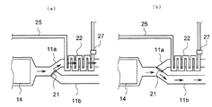
- the exhaust flow path switching valve 21 When the exhaust flow path switching valve 21 is turned on in response to an instruction signal input from the ECU 40, the upstream end of the branch exhaust passage 11b is closed. That is, the exhaust gas from the SCR 14 flows into the heat exchange exhaust passage 11a and is released to the outside air (see FIG. 2A).
- the exhaust flow path switching valve 21 is turned OFF in response to an instruction signal input from the ECU 40, the upstream end of the heat exchange exhaust passage 11a is closed. That is, the exhaust gas from the SCR 14 flows into the branch exhaust passage 11b and is released to the outside air (see FIG. 2B).
- the waste heat recovery heat exchange flow path 22 exchanges heat between the fluid flowing through the flow path and the exhaust flowing through the heat exchange exhaust passage 11a, and meanders in the heat exchange exhaust passage 11a. Is formed.
- the waste heat recovery heat exchange flow path 22 is provided on the exhaust downstream side of the SCR 14, so that the SCR 14 becomes lower than the catalyst activation temperature due to a decrease in exhaust temperature due to waste heat recovery. Can be prevented.
- the vehicle interior heating unit 23 includes an inlet tank 23a connected to the upstream fluid passage 24, an outlet tank 23b connected to the downstream fluid passage 25, and an inlet tank 23a and an outlet tank 23b.
- the heater core portion 23c and a sub tank 23d as a reservoir tank connected to the inlet tank 23a are provided.
- the heater core 23c heats the air blown into the vehicle interior by using the fluid heated in the waste heat recovery heat exchange channel 22 and flowing from the inlet tank 23a as a heat source.
- the fluid that has flowed through the heater core 23c and exchanged heat with air flows into the outlet tank 23b.
- the upstream fluid passage 24 supplies the fluid heated to the vehicle interior heating unit 23 by heat exchange with the exhaust gas in the waste heat recovery heat exchange passage 22. Therefore, the upstream fluid passage 24 is connected at its upstream end to the fluid outlet portion of the waste heat recovery heat exchange passage 22 and at the downstream end to the inlet tank 23a of the vehicle interior heating unit 23. Has been.
- the downstream fluid flow path 25 allows the fluid heat exchanged with the air in the heater core 23c to flow into the heat exchange flow path 22 for waste heat recovery.
- the downstream side fluid passage 25 is connected at its upstream end to the outlet tank 23b of the vehicle interior heating unit 23 and at its downstream end to the fluid inlet of the heat exchange passage 22 for waste heat recovery. Has been.
- the electric pump 26 pumps fluid and is provided in the upstream fluid flow path 24.
- the driving of the electric pump 26 is controlled according to an instruction signal input from the ECU 40.
- the fluid is composed of ⁇ inlet tanks 23a-heater core portions 23c-outlet tank 23b-downstream fluid passage 25 waste heat recovery heat exchange passage 22 to the upstream side fluid passage 24 which is pumped Circulates through the fluid circuit.
- the electric pump 26 may be provided in the downstream fluid flow path 25.
- the fluid temperature sensor 27 detects the temperature of the fluid heated by heat exchange with the exhaust, and is provided in the upstream fluid flow path 24 adjacent to the fluid outlet portion of the waste heat recovery heat exchange flow path 22. ing.
- the fluid temperature T WA detected by the fluid temperature sensor 27 is input to the electrically connected ECU 40.
- the ECU 40 performs various controls such as fuel injection of the engine 10, and includes a known CPU, ROM, RAM, input port, output port, and the like. In order to perform these various controls, output signals of various sensors are input to the ECU 40.
- the ECU 40 has an electric pump drive control unit 41 and a switching valve control unit 42 as some functional elements.
- these functional elements are described as being included in the ECU 40, which is an integral piece of hardware. However, any one of these functional elements may be provided in separate hardware.
- the electric pump drive control unit 41 controls the driving of the electric pump 26 according to the fluid temperature T WA detected by the fluid temperature sensor 27. More specifically, the ECU 40 stores, as the heating / heating upper limit threshold T LIM1 , a fluid temperature (for example, 50 ° C.) at which the air blown into the passenger compartment is heated by the heater core portion 23c and can be sufficiently heated. ing.
- a fluid temperature for example, 50 ° C.
- Electric pump operation control unit 41 when the fluid temperature T WA inputted from the fluid temperature sensor 27 is below the heating heat upper threshold T LIM1 inputs a drive instruction signal to the electric pump 26. On the other hand, when the fluid temperature T WA inputted from the fluid temperature sensor 27 exceeds the heating heat upper threshold T LIM1, the electric pump operation control unit 41 inputs a stop instruction signal to the electric pump 26. Thereby, it is comprised so that the useless power consumption which drives the electric pump 26 may be avoided.
- the switching valve control unit 42 controls the exhaust flow path switching valve 21 according to the fluid temperature T WA detected by the fluid temperature sensor 27. More specifically, the ECU 40 stores a temperature (for example, 80 ° C.) that prevents boiling of the fluid as the fluid temperature upper limit threshold T LIM2 . Switching valve control unit 42, the fluid temperature T WA inputted from the fluid temperature sensor 27 when following this fluid temperature upper threshold T LIM2 inputs an instruction signal to the ON exhaust flow switching valve 21. That is, the upstream end of the branch exhaust passage 11b is closed, and the exhaust flows into the heat exchange exhaust passage 11a (see FIG. 2A).
- a temperature for example, 80 ° C.
- switching valve control unit 42 inputs an instruction signal to the OFF exhaust flow switching valve 21. That is, the upstream end of the heat exchange exhaust passage 11a is closed, and the exhaust flows into the branch exhaust passage 11b (see FIG. 2B).
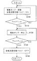
- step 100 a drive instruction signal is input from the electric pump drive control unit 41 to the electric pump 26, and at the same time, the exhaust flow path switching valve 21 is turned on from the switching valve control unit 42.
- An instruction signal is input. That is, the temperature of the fluid is raised by heat exchange with the exhaust gas in the waste heat recovery heat exchange passage 22, and the heated fluid flows into the vehicle interior heating unit 23 through the upstream fluid passage 24. Then, heating of the air blown into the passenger compartment is started.
- the fluid temperature T WA inputted from the fluid temperature sensor 27 whether or not reached the heating heat upper threshold T LIM1 is determined.
- the process returns to S100, whereas when the fluid temperature T WA exceeds the heating / heating upper limit threshold T LIM1 , the process proceeds to S120.
- stop instruction signal to the electric pump 26 is inputted from the electric pump operation control unit 41.
- cooling air heated by an engine is used as a heat source to heat air blown into the passenger compartment. For this reason, particularly at the time of starting, there is a possibility that the heat of the cooling water is taken away by the heating air for heating and the warm-up performance of the engine is deteriorated.
- a fluid circuit that is separate from the cooling water circuit of the engine 10 is provided, and the air blown into the vehicle interior using the fluid heated by the exhaust heat as a heat source. Heating.
- the heater performance can be effectively improved without degrading the warm-up performance of the engine 10.
- the waste heat recovery heat exchange passage 22 for exchanging heat between the exhaust and the fluid is provided on the exhaust downstream side of the SCR.
- the exhaust gas (NOx emission) is effectively deteriorated by avoiding that the SCR 14 is lower than the catalyst activation temperature due to a decrease in exhaust temperature due to waste heat recovery. Can be prevented.
- the vehicle heating apparatus 20B according to the second embodiment of the present invention will be described with reference to FIGS.
- the fluid that heats the air blown into the passenger compartment is used as cooling water for the engine 10, and further the warming up of the engine 10 is promoted by cooling water that is heated by waste heat recovery. is there.
- Constituent elements having the same functions as those of the first embodiment are denoted by the same reference numerals, and detailed description thereof is omitted.
- the vehicle heating device 20 ⁇ / b> B of the present embodiment includes a heat exchange exhaust passage 11 a, a branch exhaust passage 11 b, an exhaust passage switching valve 21, and a waste heat recovery heat exchange passage 22.
- the vehicle interior heating unit 23 the upstream cooling water flow path 30, the connection cooling water flow path 31, the cylinder block internal flow path 32, the water pump 33, the downstream cooling water flow path 34, and the bypass flow path 35 , A bypass valve 36, a radiator flow path 37, a coolant temperature sensor 38, and an ECU 40 are provided.
- the upstream cooling water flow path 30 supplies the cooling water heated by heat exchange with the exhaust gas in the waste heat recovery heat exchange flow path 22 to the vehicle interior heating unit 23.
- the upstream side fluid passage 24 is connected at its upstream end to the cooling water outlet of the waste heat recovery heat exchange passage 22 and at the downstream end to the inlet tank 23a of the vehicle interior heating unit 23. It is connected.
- connection cooling water flow path 31 causes the cooling water flowing through the vehicle interior heating unit 23 to flow into the cylinder block flow path 32. For this reason, the connecting coolant passage 31 is connected at its upstream end to the outlet tank 23b of the vehicle interior heating unit 23 and at its downstream end to the coolant inlet of the cylinder block passage 32. Yes.
- the in-cylinder block flow path 32 circulates cooling water flowing from the connection cooling water flow path 31 through a water jacket (not shown), and is formed in the cylinder block of the engine 10.
- the water pump 33 pumps and supplies cooling water, and is provided adjacent to the cooling water inlet of the in-cylinder block flow path 32.
- the water pump 33 is driven by power transmitted from a crankshaft (not shown) of the engine 10.
- the downstream cooling water flow path 34 causes the cooling water that has flowed through the cylinder block flow path 32 to flow into the heat exchange flow path 22 for waste heat recovery. For this reason, the downstream side cooling water flow path 34 is connected at its upstream end to the cooling water outlet part of the in-cylinder block flow path 32 and at the downstream end thereof is the cooling water inlet of the heat exchange path 22 for waste heat recovery. Connected to the department.
- the bypass flow path 35 bypasses the cooling water from the vehicle interior heating unit 23, and connects the upstream side cooling water flow path 30 and the connection cooling water flow path 31.
- the bypass valve 36 is provided in the bypass flow path 35 and selectively switches the flow path of the cooling water.
- the opening and closing of the bypass valve 36 is controlled in accordance with an instruction signal input from the electrically connected ECU 40.
- the radiator flow path 37 allows cooling water to flow into the radiator 39 that exchanges heat between the cooling water and the outside air, and connects the downstream side of the connection cooling water flow path 31 and the upstream side of the downstream cooling water flow path 34.
- a known thermostat 50 is provided at a branch portion between the radiator flow path 37 and the downstream cooling water flow path 34. When the cooling water temperature exceeds 87 ° C., the thermostat 50 causes the cooling water to flow through the radiator flow path 37. That is, the cooling water circulates in the cooling water circuit constituted by the cylinder block inner passage 32 and the radiator passage 37 (see FIG. 5C).
- the cooling water temperature sensor 38 detects the temperature of the cooling water heated by the heat exchange with the exhaust gas, and is provided in the upstream cooling water passage 30 adjacent to the cooling water outlet portion of the heat exchange passage 22 for waste heat recovery. Is provided.
- the coolant temperature T CO detected by the coolant temperature sensor 38 is inputted to the electrically connected ECU 40.
- the ECU 40 includes a bypass valve control unit 43 and a switching valve control unit 42 as some functional elements.
- Bypass valve control unit 43 depending on the coolant temperature T CO detected by the coolant temperature sensor 38, controls the bypass valve 36. More specifically, the ECU 40 stores, as the heating / heating upper limit threshold T LIM1 , a fluid temperature (for example, 50 ° C.) at which the air blown into the passenger compartment is heated by the heater core portion 23c and can be sufficiently heated. ing.
- a fluid temperature for example, 50 ° C.
- Bypass valve control unit 43 the cooling water temperature T CO input from coolant temperature sensor 38 when the following heating heating upper threshold T LIM1 inputs closing instruction signal to the bypass valve 36. That is, the cooling water heated in the waste heat recovery heat exchange flow path 22 flows into the vehicle interior heating unit 23 (see FIG. 5A).
- bypass valve control unit 43 inputs a valve-opening instruction signal to the bypass valve 36. That is, the cooling water heated in the waste heat recovery heat exchange flow path 22 flows into the bypass flow path 35 and bypasses the vehicle interior heating unit 23 (see FIG. 5B).
- Switching valve control unit 42 depending on the coolant temperature T CO detected by the coolant temperature sensor 38, and controls the exhaust flow switching valve 21. More specifically, the ECU 40 stores a temperature (for example, 80 ° C.) that prevents boiling of the cooling water as the cooling water temperature upper limit threshold T LIM3 . Switching valve control unit 42, the cooling water temperature T CO input from coolant temperature sensor 38 when the cooling water temperature upper threshold T LIM 3 below, inputs an instruction signal for turning ON the exhaust flow switching valve 21. On the other hand, the cooling water temperature T CO input from coolant temperature sensor 38 is more than the cooling water temperature upper threshold T LIM 3, the switching valve control unit 42 inputs an instruction signal to the OFF exhaust flow switching valve 21.
- a temperature for example, 80 ° C.
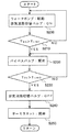
- the water pump 33 is driven by the start of the engine 10, and an instruction signal for turning on the exhaust flow path switching valve 21 is input from the switching valve control unit 42. That is, the temperature of the cooling water is raised by heat exchange with the exhaust gas in the waste heat recovery heat exchange flow path 22, and the raised cooling water flows into the vehicle interior heating unit 23 via the upstream fluid flow path 24. Then, heating of the air blown into the passenger compartment is started.
- the cooling water temperature T CO input from coolant temperature sensor 38 whether the reached heating heating upper threshold T LIM1 is determined. While the cooling water temperature T CO is returned to S200 in the following cases: heating heating upper threshold T LIM1, when the cooling water temperature T CO exceeds the heating heat upper threshold T LIM1 proceeds to S220.
- the cooling water temperature T CO input from coolant temperature sensor 38 whether or not reached in the cooling water temperature upper threshold T LIM 3 is determined. If the cooling water temperature T CO is below the cooling water temperature upper threshold T LIM 3 is returned to S220 to continue the warming up of the engine 10. On the other hand, the cooling water temperature T CO may exceed the cooling water temperature upper threshold T LIM 3 an instruction signal to turn OFF the exhaust passage switching valve 21 from the switching valve control unit 42 in S240 is input.
- the thermostat 50 in response to the cooling water temperature exceeding 87 ° C., switches the cooling water flow path from the downstream cooling water flow path 34 to the radiator flow path 37. That is, the flow path of the cooling water is switched to the cooling water circuit constituted by the in-cylinder block flow path 32 and the radiator flow path 37, and this control is returned.
- the cooling water whose temperature has been raised by heat exchange with the exhaust gas in the waste heat recovery heat exchange flow path 22 passes through the vehicle interior heating unit 23 and the cylinder block. It flows into the flow path 32. Then, when the temperature of the cooling water flowing into the heater core 23c reaches a predetermined temperature at which heating can be sufficiently performed, the cooling water bypasses the vehicle interior heating unit 23, and waste heat is exhausted until the warm-up of the engine 10 is completed. It flows into the cylinder block flow path 32 while being further heated in the recovery heat exchange flow path 22.
- the heater performance can be effectively improved while the warm-up performance of the engine 10 is improved.
- heat exchange exhaust passage 11a and the branch exhaust passage 11b have been described as being formed in the exhaust passage 11 on the exhaust downstream side of the silencer, they may be formed immediately downstream of the SCR 14, and the catalyst heater If provided, it may be formed on the exhaust upstream side of the SCR 14.
- the upstream cooling water passage 30 may further include an electric pump 26.
- the water pump 33 is an electromagnetic clutch type water pump and the driving thereof is stopped as necessary, the engine load during the warm-up operation can be effectively reduced.
- the engine 10 is not limited to a diesel engine, and may be a gasoline engine or the like.
Landscapes
- Engineering & Computer Science (AREA)
- Chemical & Material Sciences (AREA)
- Combustion & Propulsion (AREA)
- Mechanical Engineering (AREA)
- General Engineering & Computer Science (AREA)
- Physics & Mathematics (AREA)
- Thermal Sciences (AREA)
- Air-Conditioning For Vehicles (AREA)
- Exhaust Gas After Treatment (AREA)
Abstract
車両用暖房装置に関し、エンジンの暖機性能低下を防止しつつ、ヒータ性能を効果的に向上させる。 エンジン10の排気通路11に設けられ、排気通路11を流れる排気と流通させる流体との間で熱交換を行う熱交換流路22と、熱交換流路22で昇温された流体と車室内に送風される空気との間で熱交換を行うヒータコア23cと、熱交換流路22の流体出口部とヒータコア23cの流体入口部とを接続する第1の流体流路24と、ヒータコア23cの流体出口部と熱交換流路22の流体入口部とを接続する第2の流体流路25と、第1の流体流路24に設けられて流体を圧送するポンプ26とを備えた。
Description
本発明は、車両用暖房装置に関し、特に、廃熱を回収して車室内に送風される空気を加熱する車両用暖房装置に関する。
一般的に、車両用暖房装置においては、エンジンで昇温された冷却水をヒータコアに供給すると共に、この冷却水で車室内に送風される空気を加熱している。このような車両用暖房装置は、例えば特許文献1に記載されている。
ところで、エンジン始動時に暖機を促進するためには、冷却水温を早期に上昇させる必要がある。そのため、一般的なエンジンにおいては、暖機運転時は冷却水の循環流路をラジエータから迂回させることで、冷却水温を効果的に上昇させている。しかしながら、上述の従来技術のように、エンジンで昇温された冷却水を車室内に送風する空気の加熱に用いると、冷却水温の上昇に時間が掛かり、結果としてエンジンの暖機性能を低下させる可能性がある。
本発明はこのような点に鑑みてなされたもので、その目的は、エンジンの暖機性能低下を防止しつつ、ヒータ性能を効果的に向上することができる車両用暖房装置を提供することにある。
上記目的を達成するため、本発明の車両用暖房装置は、エンジンの排気通路に設けられ、該排気通路を流れる排気と流通させる流体との間で熱交換を行う熱交換流路と、前記熱交換流路で昇温された流体を流通させると共に、該流体と車室内に送風される空気との間で熱交換を行うヒータコアと、前記熱交換流路の流体出口部と前記ヒータコアの流体入口部とを接続する第1の流体流路と、前記ヒータコアの流体出口部と前記熱交換流路の流体入口部とを接続する第2の流体流路と、前記第1の流体流路もしくは前記第2の流体流路に設けられて流体を圧送するポンプとを備えることを特徴とする。
また、前記熱交換流路よりも排気上流側の排気通路から分岐して形成された分岐排気通路と、前記排気通路と前記分岐排気通路との分岐部に設けられて排気の流路を切り替える流路切替バルブとをさらに備え、前記流路切替バルブは、前記熱交換流路で昇温された流体の温度が流体の沸騰を防ぐ第1の上限閾値以下の時は、排気の流路を前記熱交換流路が設けられた排気通路にする一方、前記熱交換流路で昇温された流体の温度が前記第1の上限閾値よりも高くなると、排気の流路を前記分岐排気通路に切り替えるものであってもよい。
また、前記流体は前記エンジンの冷却水であって、前記第2の流体流路の少なくとも一部が前記エンジンのシリンダブロック内に形成されてもよい。
また、前記第1の流体流路と前記シリンダブロックよりも流体上流側に位置する前記第2の流体流路とを接続して、冷却水の流路を前記ヒータコアから迂回させるバイパス流路と、冷却水の流路を前記ヒータコアもしくは前記バイパス流路に切り替えるバイパスバルブとをさらに備え、前記バイパスバルブは、前記ヒータコアに流入する冷却水の温度が、暖房用の熱源として空気を十分に加熱できる第2の上限閾値よりも高くなると、冷却水の流路を前記バイパス流路に切り替えるものであってよい。
また、前記排気通路に排気を浄化する排気浄化触媒が設けられ、前記熱交換流路は該排気浄化触媒よりも排気下流側の排気通路に設けられてもよい。
本発明の車両用暖房装置によれば、エンジンの暖機性能低下を防止しつつ、ヒータ性能を効果的に向上することができる。
以下、図面により、本発明に係る車両用暖房装置の各実施形態について説明する。同一の部品には同一の符号を付してあり、それらの名称および機能も同じである。したがって、それらについての詳細な説明は繰返さない。
[第一実施形態]
まず、図1に基づいて、第一実施形態の車両用暖房装置20Aが搭載される車両の排気系から説明する。
まず、図1に基づいて、第一実施形態の車両用暖房装置20Aが搭載される車両の排気系から説明する。
本実施形態の排気系において、ディーゼルエンジン(以下、単にエンジンという)10の排気通路11には排気上流側から順に、酸化触媒(Diesel Oxidation Catalyst:以下、DOCという)12、ディーゼル・パティキュレイト・フィルタ(Diesel Particulate Filter、以下、DPFという)13、選択的還元触媒(Selective Catalytic Reduction:以下、SCRという)14が設けられている。
DOC12は、排気中のNOを酸化してNO2を生成して、排気中のNOに対するNO2の比率を増加させることで、SCR14による脱硝効率を高めるように機能する。
DPF13は、排気中の粒子状物質(以下、PMという)を捕集すると共に、PMの捕集量が所定量を超えると、蓄積したPMを焼却除去する再生が行われる。このDPF13の再生は、排気上流側のDOC12にポスト噴射により未燃燃料を供給し、酸化による熱で排気温度を上昇することで行われる。
SCR14は、図示しない尿素水インジェクタにより排気通路11内に噴霧された尿素水から生成されるアンモニアを吸着するとともに、吸着したアンモニアで通過する排気中からNOxを還元浄化する。
次に、本実施形態の車両用暖房装置20Aの詳細構成について説明する。車両用暖房装置20Aは、熱交換用排気通路11aと、分岐排気通路11bと、排気流路切替バルブ21と、廃熱回収用熱交換流路22と、車室内暖房ユニット23と、上流側流体流路24と、下流側流体流路25と、電動ポンプ26と、流体温度センサ27と、電子制御ユニット(以下、ECUという)40とを備えている。
なお、本実施形態において、廃熱回収用熱交換流路22は本発明の熱交換流路に相当し、上流側流体流路24は本発明の第1の流体流路に相当し、下流側流体流路25は本発明の第2の流体流路に相当する。
熱交換用排気通路11aは、SCR14や図示しない消音器よりも排気下流側の排気通路11に形成されている。この熱交換用排気通路11a内には、詳細を後述する廃熱回収用熱交換流路22が介装されている。
分岐排気通路11bは、SCR14と廃熱回収用熱交換流路22との間に位置する排気通路11から分岐して形成されている。本実施形態において、この分岐排気通路11bと熱交換用排気通路11aとは、排気を外部に放出するテールパイプとしても機能する。
排気流路切替バルブ21は、例えば公知のバタフライバルブであって、熱交換用排気通路11aと分岐排気通路11bとの分岐部に設けられている。この排気流路切替バルブ21は、ECU40から入力される指示信号に応じてONにされると、分岐排気通路11bの上流端を閉鎖する。すなわち、SCR14からの排気は熱交換用排気通路11aに流入して外気に放出される(図2(a)参照)。一方、排気流路切替バルブ21は、ECU40から入力される指示信号に応じてOFFにされると、熱交換用排気通路11aの上流端を閉鎖する。すなわち、SCR14からの排気は分岐排気通路11bに流入して外気に放出される(図2(b)参照)。
廃熱回収用熱交換流路22は、その流路内を流通させる流体と熱交換用排気通路11a内を流れる排気との間で熱交換を行うもので、熱交換用排気通路11a内に蛇行して形成されている。本実施形態において、この廃熱回収用熱交換流路22は、SCR14よりも排気下流側に設けられているので、廃熱回収による排気温度の低下によりSCR14が触媒活性温度よりも低くなることを防止することができる。
車室内暖房ユニット23は、上流側流体流路24が接続された入口タンク23aと、下流側流体流路25が接続された出口タンク23bと、入口タンク23aと出口タンク23bとの間に介装されたヒータコア部23cと、入口タンク23aに接続されたリザーバタンクとしてのサブタンク23dとを備えている。ヒータコア部23cは、廃熱回収用熱交換流路22で昇温されて入口タンク23aから流入する流体を熱源として、車室内に送風される空気を加熱する。ヒータコア部23cを流れて空気と熱交換された流体は、出口タンク23bに流入する。
上流側流体流路24は、廃熱回収用熱交換流路22で排気との熱交換により昇温された流体を車室内暖房ユニット23に供給する。このため、上流側流体流路24は、その上流端部を廃熱回収用熱交換流路22の流体出口部に接続されると共に、下流端部を車室内暖房ユニット23の入口タンク23aに接続されている。
下流側流体流路25は、ヒータコア部23cで空気と熱交換された流体を廃熱回収用熱交換流路22に流入させる。このため、下流側流体流路25は、その上流端部を車室内暖房ユニット23の出口タンク23bに接続されると共に、下流端部を廃熱回収用熱交換流路22の流体入口部に接続されている。
電動ポンプ26は、流体を圧送するもので、上流側流体流路24に設けられている。この電動ポンプ26の駆動は、ECU40から入力される指示信号に応じて制御される。電動ポンプ26が駆動すると、圧送される流体は廃熱回収用熱交換流路22~上流側流体流路24~入口タンク23a~ヒータコア部23c~出口タンク23b~下流側流体流路25で構成される流体回路を循環する。なお、電動ポンプ26は、下流側流体流路25に設けられてもよい。
流体温度センサ27は、排気との熱交換により昇温された流体の温度を検出するもので、廃熱回収用熱交換流路22の流体出口部と隣接する上流側流体流路24に設けられている。この流体温度センサ27で検出される流体温度TWAは、電気的に接続されたECU40に入力される。
ECU40は、エンジン10の燃料噴射等の各種制御を行うもので、公知のCPUやROM、RAM、入力ポート、出力ポート等を備え構成されている。この各種制御を行うため、ECU40には各種センサ類の出力信号が入力される。
また、ECU40は、電動ポンプ駆動制御部41と、切替バルブ制御部42とを一部の機能要素として有する。これら各機能要素は、本実施形態では一体のハードウェアであるECU40に含まれるものとして説明するが、これらのいずれか一部を別体のハードウェアに設けることもできる。
電動ポンプ駆動制御部41は、流体温度センサ27で検出される流体温度TWAに応じて電動ポンプ26の駆動を制御する。より詳しくは、ECU40には、車室内に送風される空気をヒータコア部23cで加熱して、暖房を十分に行うことができる流体温度(例えば、50℃)が暖房加熱上限閾値TLIM1として記憶されている。
電動ポンプ駆動制御部41は、流体温度センサ27から入力される流体温度TWAが暖房加熱上限閾値TLIM1以下の時は、電動ポンプ26に駆動指示信号を入力する。一方、流体温度センサ27から入力される流体温度TWAが暖房加熱上限閾値TLIM1を超えると、電動ポンプ駆動制御部41は電動ポンプ26に停止指示信号を入力する。これにより、電動ポンプ26を駆動させる無駄な電力消費が回避されるように構成されている。
切替バルブ制御部42は、流体温度センサ27で検出される流体温度TWAに応じて、排気流路切替バルブ21を制御する。より詳しくは、ECU40には、流体の沸騰を防ぐ温度(例えば、80℃)が流体温度上限閾値TLIM2として記憶されている。切替バルブ制御部42は、流体温度センサ27から入力される流体温度TWAがこの流体温度上限閾値TLIM2以下の時は、排気流路切替バルブ21をONにする指示信号を入力する。すなわち、分岐排気通路11bの上流端が閉鎖されて、排気は熱交換用排気通路11aに流入する(図2(a)参照)。
一方、流体温度センサ27から入力される流体温度TWAが流体温度上限閾値TLIM2を超えると、切替バルブ制御部42は排気流路切替バルブ21をOFFにする指示信号を入力する。すなわち、熱交換用排気通路11aの上流端が閉鎖されて、排気は分岐排気通路11bに流入する(図2(b)参照)。
次に、図3に基づいて、本実施形態の車両用暖房装置20Aによる制御フローを説明する。なお、本制御はエンジン10の始動(イグニッションスイッチのキースイッチON)と同時にスタートする。
ステップ(以下、ステップを単にSと記載する)100では、電動ポンプ駆動制御部41から電動ポンプ26に駆動指示信号が入力されると同時に、切替バルブ制御部42から排気流路切替バルブ21をONにする指示信号が入力される。すなわち、廃熱回収用熱交換流路22で流体が排気との熱交換により昇温されると共に、昇温された流体が上流側流体流路24を介して車室内暖房ユニット23に流入して、車室内に送風される空気の加熱が開始される。
S110では、流体温度センサ27から入力される流体温度TWAが暖房加熱上限閾値TLIM1に達したか否かが判定される。流体温度TWAが暖房加熱上限閾値TLIM1以下の場合はS100に戻される一方、流体温度TWAが暖房加熱上限閾値TLIM1を超えた場合はS120に進む。
S120では、流体温度TWAが暖房加熱上限閾値TLIM1に達したことを受けて、無駄な電力消費を回避すべく、電動ポンプ駆動制御部41から電動ポンプ26に停止指示信号が入力される。
S130では、流体温度センサ27から入力される流体温度TWAが流体温度上限閾値TLIM2に達したか否かが判定される。流体温度TWAが流体温度上限閾値TLIM2を超えた場合は、流体の沸騰を回避すべく、S140で切替バルブ制御部42から排気流路切替バルブ21をOFFにする指示信号が入力されて本制御はリターンされる。
次に、本実施形態に係る車両用暖房装置20Aによる作用効果を説明する。
一般的な車両用暖房装置では、エンジンで昇温される冷却水を熱源として、車室内に送風される空気を加熱している。このため、特に始動時には、暖房用の空気の加熱に冷却水の熱が奪われて、エンジンの暖機性能を低下させる虞があった。
これに対し、本実施形態の車両用暖房装置20Aでは、エンジン10の冷却水回路とは別個の流体回路を設けて、排気熱で昇温された流体を熱源として車室内に送風される空気を加熱している。
したがって、本実施形態の車両用暖房装置20Aによれば、エンジン10の暖機性能を低下させることなく、ヒータ性能を効果的に向上することができる。
また、本実施形態の車両用暖房装置20Aでは、排気と流体との熱交換を行う廃熱回収用熱交換流路22は、SCR14よりも排気下流側に位置して設けられている。
したがって、本実施形態の車両用暖房装置20Aによれば、廃熱回収による排気温度の低下でSCR14が触媒活性温度よりも低下することを回避して、排ガス(NOx排出)の悪化を効果的に防止することができる。
[第二実施形態]
以下、図4~6に基づいて、本発明の第二実施形態に係る車両用暖房装置20Bを説明する。本発明の第二実施形態は、車室内に送風される空気を加熱する流体をエンジン10の冷却水とし、さらに廃熱回収により昇温される冷却水でエンジン10の暖機を促進させるものである。第一実施形態と同一の機能を有する構成要素については同一の符号を用い、それらの詳細な説明は省略する。
以下、図4~6に基づいて、本発明の第二実施形態に係る車両用暖房装置20Bを説明する。本発明の第二実施形態は、車室内に送風される空気を加熱する流体をエンジン10の冷却水とし、さらに廃熱回収により昇温される冷却水でエンジン10の暖機を促進させるものである。第一実施形態と同一の機能を有する構成要素については同一の符号を用い、それらの詳細な説明は省略する。
本実施形態の車両用暖房装置20Bは、図4に示すように、熱交換用排気通路11aと、分岐排気通路11bと、排気流路切替バルブ21と、廃熱回収用熱交換流路22と、車室内暖房ユニット23と、上流側冷却水流路30と、接続用冷却水流路31と、シリンダブロック内流路32と、ウォータポンプ33と、下流側冷却水流路34と、バイパス流路35と、バイパスバルブ36と、ラジエータ用流路37と、冷却水温センサ38と、ECU40とを備えている。
上流側冷却水流路30は、廃熱回収用熱交換流路22で排気との熱交換により昇温された冷却水を車室内暖房ユニット23に供給する。このため、上流側流体流路24は、その上流端部を廃熱回収用熱交換流路22の冷却水出口部に接続されると共に、下流端部を車室内暖房ユニット23の入口タンク23aに接続されている。
接続用冷却水流路31は、車室内暖房ユニット23を流通した冷却水をシリンダブロック内流路32に流入させる。このため、接続用冷却水流路31は、その上流端部を車室内暖房ユニット23の出口タンク23bに接続されると共に、下流端部をシリンダブロック内流路32の冷却水入口部に接続されている。
シリンダブロック内流路32は、接続用冷却水流路31から流入する冷却水を図示しないウォータジャケットに流通させるもので、エンジン10のシリンダブロック内に形成されている。
ウォータポンプ33は、冷却水を圧送供給するもので、シリンダブロック内流路32の冷却水入口部に隣接して設けられている。このウォータポンプ33は、エンジン10の図示しないクランクシャフトから伝達される動力で駆動される。
下流側冷却水流路34は、シリンダブロック内流路32を流通した冷却水を廃熱回収用熱交換流路22に流入させる。このため、下流側冷却水流路34は、その上流端部をシリンダブロック内流路32の冷却水出口部に接続されると共に、下流端部を廃熱回収用熱交換流路22の冷却水入口部に接続されている。
バイパス流路35は、冷却水を車室内暖房ユニット23から迂回させるもので、上流側冷却水流路30と接続用冷却水流路31とを接続する。
バイパスバルブ36は、バイパス流路35に設けられており、冷却水の流路を選択的に切り替える。このバイパスバルブ36の開閉は、電気的に接続されたECU40から入力される指示信号に応じて制御される。このバイパスバルブ36が閉弁すると、冷却水は車室内暖房ユニット23に流入する一方(図5(a)参照)、バイパスバルブ36が開弁すると、冷却水はバイパス流路35に流入する(図5(b)参照)。
ラジエータ用流路37は、冷却水と外気との熱交換を行うラジエータ39に冷却水を流入させるもので、接続用冷却水流路31の下流側と下流側冷却水流路34の上流側とを接続する。また、ラジエータ用流路37と下流側冷却水流路34との分岐部には、公知のサーモスタット50が設けられている。このサーモスタット50は、冷却水温が87℃を超えると冷却水をラジエータ用流路37に流通させる。すなわち、冷却水はシリンダブロック内流路32とラジエータ用流路37とで構成される冷却水回路を循環する(図5(c)参照)。
冷却水温センサ38は、排気との熱交換により昇温された冷却水の温度を検出するもので、廃熱回収用熱交換流路22の冷却水出口部と隣接する上流側冷却水流路30に設けられている。この冷却水温センサ38で検出される冷却水温度TCOは、電気的に接続されたECU40に入力される。
ECU40は、バイパスバルブ制御部43と、切替バルブ制御部42とを一部の機能要素として備えている。
バイパスバルブ制御部43は、冷却水温センサ38で検出される冷却水温度TCOに応じて、バイパスバルブ36を制御する。より詳しくは、ECU40には、車室内に送風される空気をヒータコア部23cで加熱して、暖房を十分に行うことができる流体温度(例えば、50℃)が暖房加熱上限閾値TLIM1として記憶されている。
バイパスバルブ制御部43は、冷却水温センサ38から入力される冷却水温度TCOが暖房加熱上限閾値TLIM1以下の時は、バイパスバルブ36に閉弁指示信号を入力する。すなわち、廃熱回収用熱交換流路22で昇温された冷却水は車室内暖房ユニット23に流入する(図5(a)参照)。
一方、冷却水温センサ38から入力される冷却水温度TCOが暖房加熱上限閾値TLIM1を超えると、バイパスバルブ制御部43はバイパスバルブ36に開弁指示信号を入力する。すなわち、廃熱回収用熱交換流路22で昇温された冷却水はバイパス流路35に流入して、車室内暖房ユニット23を迂回する(図5(b)参照)。
切替バルブ制御部42は、冷却水温センサ38で検出される冷却水温度TCOに応じて、排気流路切替バルブ21を制御する。より詳しくは、ECU40には、冷却水の沸騰を防ぐ温度(例えば、80℃)が冷却水温度上限閾値TLIM3として記憶されている。切替バルブ制御部42は、冷却水温センサ38から入力される冷却水温度TCOがこの冷却水温度上限閾値TLIM3以下の時は、排気流路切替バルブ21をONにする指示信号を入力する。一方、冷却水温センサ38から入力される冷却水温度TCOが冷却水温度上限閾値TLIM3を超えると、切替バルブ制御部42は排気流路切替バルブ21をOFFにする指示信号を入力する。
次に、図6に基づいて、本実施形態の車両用暖房装置20Bによる制御フローを説明する。本制御はエンジン10の始動(イグニッションスイッチのキースイッチON)と同時にスタートする。
S200では、エンジン10の始動によりウォータポンプ33が駆動すると共に、切替バルブ制御部42から排気流路切替バルブ21をONにする指示信号が入力される。すなわち、冷却水が廃熱回収用熱交換流路22で排気との熱交換により昇温されると共に、昇温された冷却水が上流側流体流路24を介して車室内暖房ユニット23に流入して、車室内に送風される空気の加熱が開始される。
その後、S210では、冷却水温センサ38から入力される冷却水温度TCOが暖房加熱上限閾値TLIM1に達したか否かが判定される。冷却水温度TCOが暖房加熱上限閾値TLIM1以下の場合はS200に戻される一方、冷却水温度TCOが暖房加熱上限閾値TLIM1を超えた場合はS220に進む。
S220では、冷却水温度TCOが暖房加熱上限閾値TLIM1に達したことを受けて、バイパスバルブ制御部43からバイパスバルブ36に開弁指示信号が入力される。すなわち、冷却水は車室内暖房ユニット23を迂回する。
S230では、冷却水温センサ38から入力される冷却水温度TCOが冷却水温度上限閾値TLIM3に達したか否かが判定される。冷却水温度TCOが冷却水温度上限閾値TLIM3以下の場合は、エンジン10の暖機を継続するためにS220に戻される。一方、冷却水温度TCOが冷却水温度上限閾値TLIM3を超えた場合は、S240で切替バルブ制御部42から排気流路切替バルブ21をOFFにする指示信号が入力される。
さらに、S250では、冷却水温が87℃を超えたことを受けて、サーモスタット50により冷却水の流路が下流側冷却水流路34からラジエータ用流路37に切り替えられる。すなわち、冷却水の流路がシリンダブロック内流路32とラジエータ用流路37とで構成される冷却水回路に切り替えられ、本制御はリターンされる。
次に、本実施形態の車両用暖房装置20Bによる作用効果を説明する。なお、第一実施形態の車両用暖房装置20Aと同様の作用効果を奏するものについては説明を省略する。
本実施形態の車両用暖房装置20Bでは、エンジン10の始動後、廃熱回収用熱交換流路22で排気との熱交換により昇温された冷却水は、車室内暖房ユニット23とシリンダブロック内流路32とに流入する。そして、ヒータコア部23cに流入する冷却水の温度が暖房を十分に行える所定の温度に達すると、冷却水は車室内暖房ユニット23を迂回しつつ、エンジン10の暖機が終了するまで、廃熱回収用熱交換流路22でさらに加熱されながらシリンダブロック内流路32に流入する。すなわち、廃熱回収により加熱した冷却水でヒータコア部23cが暖房を十分に行える温度まで昇温した後においても、この廃熱回収による冷却水の加熱は継続されて、エンジン10の暖機が促進される。
したがって、本実施形態の車両用暖房装置20Bによれば、エンジン10の暖機性能を向上させつつ、ヒータ性能も効果的に向上することができる。
なお、本発明は、上述の各実施形態に限定されるものではなく、本発明の趣旨を逸脱しない範囲で、適宜変形して実施することが可能である。
例えば、熱交換用排気通路11aや分岐排気通路11bは、消音器よりも排気下流側の排気通路11に形成されるものとして説明したが、SCR14の直下流に形成されてもよく、触媒ヒータを備えていればSCR14よりも排気上流側に形成されてもよい。
また、第二実施形態において、上流側冷却水流路30に電動ポンプ26をさらに備える構成としてもよい。この場合は、ウォータポンプ33を電磁クラッチ式のウォータポンプにして、その駆動を必要に応じて停止させれば、暖機運転時のエンジン負荷を効果的に低減することが可能になる。
また、エンジン10は、ディーゼルエンジンに限定されず、ガソリンエンジン等であってもよい。
10 エンジン
11 排気通路
11a 熱交換用排気通路
11b 分岐排気通路
21 排気流路切替バルブ
22 廃熱回収用熱交換流路(熱交換流路)
23 車室内暖房ユニット
23c ヒータコア部
24 上流側流体流路(第1の流体流路)
25 下流側流体流路(第2の流体流路)
26 電動ポンプ
40 ECU
11 排気通路
11a 熱交換用排気通路
11b 分岐排気通路
21 排気流路切替バルブ
22 廃熱回収用熱交換流路(熱交換流路)
23 車室内暖房ユニット
23c ヒータコア部
24 上流側流体流路(第1の流体流路)
25 下流側流体流路(第2の流体流路)
26 電動ポンプ
40 ECU
Claims (5)
- エンジンの排気通路に設けられ、該排気通路を流れる排気と流通させる流体との間で熱交換を行う熱交換流路と、
前記熱交換流路で昇温された流体を流通させると共に、該流体と車室内に送風される空気との間で熱交換を行うヒータコアと、
前記熱交換流路の流体出口部と前記ヒータコアの流体入口部とを接続する第1の流体流路と、
前記ヒータコアの流体出口部と前記熱交換流路の流体入口部とを接続する第2の流体流路と、
前記第1の流体流路もしくは前記第2の流体流路に設けられて流体を圧送するポンプと、を備えることを特徴とする車両用暖房装置。 - 前記熱交換流路よりも排気上流側の排気通路から分岐して形成された分岐排気通路と、
前記排気通路と前記分岐排気通路との分岐部に設けられて排気の流路を切り替える流路切替バルブと、をさらに備え、
前記流路切替バルブは、前記熱交換流路で昇温された流体の温度が流体の沸騰を防ぐ第1の上限閾値以下の時は、排気の流路を前記熱交換流路が設けられた排気通路にする一方、前記熱交換流路で昇温された流体の温度が前記第1の上限閾値よりも高くなると、排気の流路を前記分岐排気通路に切り替える請求項1に記載の車両用暖房装置。 - 前記流体は前記エンジンの冷却水であって、前記第2の流体流路の少なくとも一部が前記エンジンのシリンダブロック内に形成される請求項1又は2に記載の車両用暖房装置。
- 前記第1の流体流路と前記シリンダブロックよりも流体上流側に位置する前記第2の流体流路とを接続して、冷却水の流路を前記ヒータコアから迂回させるバイパス流路と、
冷却水の流路を前記ヒータコアもしくは前記バイパス流路に切り替えるバイパスバルブと、をさらに備え、
前記バイパスバルブは、前記ヒータコアに流入する冷却水の温度が、暖房用の熱源として空気を十分に加熱できる第2の上限閾値よりも高くなると、冷却水の流路を前記バイパス流路に切り替える請求項3に記載の車両用暖房装置。 - 前記排気通路に排気を浄化する排気浄化触媒が設けられ、前記熱交換流路は該排気浄化触媒よりも排気下流側の排気通路に設けられる請求項1から4の何れかに記載の車両用暖房装置。
Applications Claiming Priority (2)
| Application Number | Priority Date | Filing Date | Title |
|---|---|---|---|
| JP2012126041A JP6028397B2 (ja) | 2012-06-01 | 2012-06-01 | 車両用暖房装置 |
| JP2012-126041 | 2012-06-01 |
Publications (1)
| Publication Number | Publication Date |
|---|---|
| WO2013180282A1 true WO2013180282A1 (ja) | 2013-12-05 |
Family
ID=49673465
Family Applications (1)
| Application Number | Title | Priority Date | Filing Date |
|---|---|---|---|
| PCT/JP2013/065224 Ceased WO2013180282A1 (ja) | 2012-06-01 | 2013-05-31 | 車両用暖房装置 |
Country Status (2)
| Country | Link |
|---|---|
| JP (1) | JP6028397B2 (ja) |
| WO (1) | WO2013180282A1 (ja) |
Cited By (3)
| Publication number | Priority date | Publication date | Assignee | Title |
|---|---|---|---|---|
| CN108757123A (zh) * | 2018-06-01 | 2018-11-06 | 天津大学 | 船舶多级scr串联系统及其控制方法 |
| CN114571950A (zh) * | 2022-03-28 | 2022-06-03 | 柳州五菱新能源汽车有限公司 | 一种发动机排气余热利用装置和车辆 |
| US11407283B2 (en) * | 2018-04-30 | 2022-08-09 | Tiger Tool International Incorporated | Cab heating systems and methods for vehicles |
Families Citing this family (2)
| Publication number | Priority date | Publication date | Assignee | Title |
|---|---|---|---|---|
| KR101724909B1 (ko) | 2015-09-23 | 2017-04-07 | 현대자동차주식회사 | 자동차용 배기열 회수 및 egr 제어 시스템 |
| JP2017065653A (ja) * | 2015-10-02 | 2017-04-06 | トヨタ自動車株式会社 | 車両用熱利用装置 |
Citations (4)
| Publication number | Priority date | Publication date | Assignee | Title |
|---|---|---|---|---|
| JPS5914706U (ja) * | 1982-07-20 | 1984-01-28 | マツダ株式会社 | 水冷エンジン搭載車の暖房装置 |
| JPS5918010A (ja) * | 1982-07-20 | 1984-01-30 | Mazda Motor Corp | 水冷エンジン搭載車の暖房装置 |
| JP2006524160A (ja) * | 2003-04-24 | 2006-10-26 | プジョー・シトロエン・オトモビル・ソシエテ・アノニム | 自動車のキャビンを加熱する方法及び装置 |
| JP2008223488A (ja) * | 2007-03-08 | 2008-09-25 | Toyota Motor Corp | ハイブリッド車両の冷却系システム |
-
2012
- 2012-06-01 JP JP2012126041A patent/JP6028397B2/ja not_active Expired - Fee Related
-
2013
- 2013-05-31 WO PCT/JP2013/065224 patent/WO2013180282A1/ja not_active Ceased
Patent Citations (4)
| Publication number | Priority date | Publication date | Assignee | Title |
|---|---|---|---|---|
| JPS5914706U (ja) * | 1982-07-20 | 1984-01-28 | マツダ株式会社 | 水冷エンジン搭載車の暖房装置 |
| JPS5918010A (ja) * | 1982-07-20 | 1984-01-30 | Mazda Motor Corp | 水冷エンジン搭載車の暖房装置 |
| JP2006524160A (ja) * | 2003-04-24 | 2006-10-26 | プジョー・シトロエン・オトモビル・ソシエテ・アノニム | 自動車のキャビンを加熱する方法及び装置 |
| JP2008223488A (ja) * | 2007-03-08 | 2008-09-25 | Toyota Motor Corp | ハイブリッド車両の冷却系システム |
Cited By (5)
| Publication number | Priority date | Publication date | Assignee | Title |
|---|---|---|---|---|
| US11407283B2 (en) * | 2018-04-30 | 2022-08-09 | Tiger Tool International Incorporated | Cab heating systems and methods for vehicles |
| CN108757123A (zh) * | 2018-06-01 | 2018-11-06 | 天津大学 | 船舶多级scr串联系统及其控制方法 |
| CN108757123B (zh) * | 2018-06-01 | 2023-10-10 | 天津大学 | 船舶多级scr串联系统及其控制方法 |
| CN114571950A (zh) * | 2022-03-28 | 2022-06-03 | 柳州五菱新能源汽车有限公司 | 一种发动机排气余热利用装置和车辆 |
| CN114571950B (zh) * | 2022-03-28 | 2024-05-07 | 柳州五菱新能源汽车有限公司 | 一种发动机排气余热利用装置和车辆 |
Also Published As
| Publication number | Publication date |
|---|---|
| JP2013249012A (ja) | 2013-12-12 |
| JP6028397B2 (ja) | 2016-11-16 |
Similar Documents
| Publication | Publication Date | Title |
|---|---|---|
| JP6019754B2 (ja) | 尿素水解凍装置 | |
| KR101724909B1 (ko) | 자동차용 배기열 회수 및 egr 제어 시스템 | |
| JP4900002B2 (ja) | 内燃機関の排気浄化システム | |
| JP5383615B2 (ja) | 後処理バーナシステムの暖機方法 | |
| JP4592504B2 (ja) | 排気浄化装置 | |
| JP6028397B2 (ja) | 車両用暖房装置 | |
| JP6024217B2 (ja) | 変速機の暖機装置 | |
| JP6056201B2 (ja) | エンジンの暖機装置 | |
| JP5867151B2 (ja) | 内燃機関の排気浄化装置 | |
| JP5867150B2 (ja) | 内燃機関の排気浄化装置 | |
| CN113167159B (zh) | 后处理系统 | |
| CN104838100B (zh) | 内燃机的排气净化系统 | |
| JP6015198B2 (ja) | 還元剤添加システム | |
| JP2013092106A (ja) | 内燃機関の排気浄化装置 | |
| KR101664687B1 (ko) | 배기가스 후처리장치용 냉각팬 제어 장치 및 방법 | |
| JP4640145B2 (ja) | 内燃機関の排気浄化システム | |
| JP4461995B2 (ja) | 内燃機関の排気浄化装置 | |
| JP2017053327A (ja) | 排気浄化装置 | |
| JP6593015B2 (ja) | 内燃機関の排気ガス浄化システム及び内燃機関 | |
| JP2015068266A (ja) | 排気ガス浄化システム及び排気ガス浄化方法 | |
| JP2020101103A (ja) | 内燃機関の排気熱回収装置 | |
| JP2011021485A (ja) | 自動車用排気浄化装置 | |
| JP2008128066A (ja) | 排気浄化装置 | |
| JP2018044498A (ja) | 排気浄化装置及び排気浄化方法 | |
| WO2011129051A1 (ja) | 後処理バーナシステムの燃焼昇温制御方法及び装置 |
Legal Events
| Date | Code | Title | Description |
|---|---|---|---|
| 121 | Ep: the epo has been informed by wipo that ep was designated in this application |
Ref document number: 13796708 Country of ref document: EP Kind code of ref document: A1 |
|
| NENP | Non-entry into the national phase |
Ref country code: DE |
|
| 122 | Ep: pct application non-entry in european phase |
Ref document number: 13796708 Country of ref document: EP Kind code of ref document: A1 |