WO2013179474A1 - タッチセンサシステム - Google Patents
タッチセンサシステム Download PDFInfo
- Publication number
- WO2013179474A1 WO2013179474A1 PCT/JP2012/064240 JP2012064240W WO2013179474A1 WO 2013179474 A1 WO2013179474 A1 WO 2013179474A1 JP 2012064240 W JP2012064240 W JP 2012064240W WO 2013179474 A1 WO2013179474 A1 WO 2013179474A1
- Authority
- WO
- WIPO (PCT)
- Prior art keywords
- area
- capacitance
- touch
- detection
- value
- Prior art date
- Legal status (The legal status is an assumption and is not a legal conclusion. Google has not performed a legal analysis and makes no representation as to the accuracy of the status listed.)
- Ceased
Links
Images







Classifications
-
- G—PHYSICS
- G06—COMPUTING OR CALCULATING; COUNTING
- G06F—ELECTRIC DIGITAL DATA PROCESSING
- G06F3/00—Input arrangements for transferring data to be processed into a form capable of being handled by the computer; Output arrangements for transferring data from processing unit to output unit, e.g. interface arrangements
- G06F3/01—Input arrangements or combined input and output arrangements for interaction between user and computer
- G06F3/03—Arrangements for converting the position or the displacement of a member into a coded form
- G06F3/041—Digitisers, e.g. for touch screens or touch pads, characterised by the transducing means
- G06F3/044—Digitisers, e.g. for touch screens or touch pads, characterised by the transducing means by capacitive means
- G06F3/0446—Digitisers, e.g. for touch screens or touch pads, characterised by the transducing means by capacitive means using a grid-like structure of electrodes in at least two directions, e.g. using row and column electrodes
-
- G—PHYSICS
- G06—COMPUTING OR CALCULATING; COUNTING
- G06F—ELECTRIC DIGITAL DATA PROCESSING
- G06F3/00—Input arrangements for transferring data to be processed into a form capable of being handled by the computer; Output arrangements for transferring data from processing unit to output unit, e.g. interface arrangements
- G06F3/01—Input arrangements or combined input and output arrangements for interaction between user and computer
- G06F3/03—Arrangements for converting the position or the displacement of a member into a coded form
- G06F3/041—Digitisers, e.g. for touch screens or touch pads, characterised by the transducing means
- G06F3/044—Digitisers, e.g. for touch screens or touch pads, characterised by the transducing means by capacitive means
-
- G—PHYSICS
- G06—COMPUTING OR CALCULATING; COUNTING
- G06F—ELECTRIC DIGITAL DATA PROCESSING
- G06F3/00—Input arrangements for transferring data to be processed into a form capable of being handled by the computer; Output arrangements for transferring data from processing unit to output unit, e.g. interface arrangements
- G06F3/01—Input arrangements or combined input and output arrangements for interaction between user and computer
- G06F3/03—Arrangements for converting the position or the displacement of a member into a coded form
- G06F3/041—Digitisers, e.g. for touch screens or touch pads, characterised by the transducing means
- G06F3/0416—Control or interface arrangements specially adapted for digitisers
- G06F3/04166—Details of scanning methods, e.g. sampling time, grouping of sub areas or time sharing with display driving
-
- G—PHYSICS
- G06—COMPUTING OR CALCULATING; COUNTING
- G06F—ELECTRIC DIGITAL DATA PROCESSING
- G06F3/00—Input arrangements for transferring data to be processed into a form capable of being handled by the computer; Output arrangements for transferring data from processing unit to output unit, e.g. interface arrangements
- G06F3/01—Input arrangements or combined input and output arrangements for interaction between user and computer
- G06F3/03—Arrangements for converting the position or the displacement of a member into a coded form
- G06F3/041—Digitisers, e.g. for touch screens or touch pads, characterised by the transducing means
- G06F3/0416—Control or interface arrangements specially adapted for digitisers
- G06F3/0418—Control or interface arrangements specially adapted for digitisers for error correction or compensation, e.g. based on parallax, calibration or alignment
- G06F3/04186—Touch location disambiguation
Definitions
- the present invention relates to a touch sensor system that detects pen input and finger input input to a touch panel having a plurality of capacitances arranged in a matrix.
- a touch sensor system that detects distribution of a plurality of capacitance values respectively formed at intersections of a plurality of first signal lines and a plurality of second signal lines is disclosed in Patent Document 1. And in the touch sensor system which detects distribution of the conventional electrostatic capacitance value, as shown in patent document 2, it tried to recognize the part of the finger and hand which are touching the touch panel by signal processing.
- FIG. 12 is a block diagram showing a configuration of a conventional touch sensor system 91 disclosed in Patent Document 3.
- the touch sensor system 91 includes a touch panel 93 and a capacitance value distribution detection circuit 92.
- the touch panel 93 includes drive lines HL1 to HLn arranged in parallel to each other along the horizontal direction, sense lines VL1 to VLm arranged in parallel to each other in the vertical direction, drive lines HL1 to HLn, and sense lines VL1 to And a plurality of capacitances formed at intersections with VLm.
- the electrostatic capacitance value distribution detection circuit 92 includes a driver 95.
- the driver 95 drives each capacitance by applying a voltage to the drive lines HL1 to HLn based on the code sequence.
- the capacitance value distribution detection circuit 92 is provided with a sense amplifier 96.
- the sense amplifier 96 reads out the linear sum of the voltages corresponding to the respective capacitances driven by the driver 95 through the sense lines VL1 to VLm, and supplies it to the AD converter 98.
- the AD converter 98 AD converts the linear sum of the voltages corresponding to the respective capacitances read through the sense lines VL1 to VLm, and supplies the result to the capacitance distribution calculation unit 99.
- the capacitance distribution calculation unit 99 calculates the capacitance distribution on the touch panel 93 based on the linear sum of the voltages corresponding to the respective capacitances supplied from the AD converter 98 and the code series, and the touch recognition unit 90. To supply.
- the touch recognition unit 90 recognizes the touched position on the touch panel 93 based on the capacitance distribution supplied from the capacitance distribution calculation unit 99.
- the capacitance value distribution detection circuit 92 has a timing generator 97.
- the timing generator 97 generates a signal that defines the operation of the driver 95, a signal that defines the operation of the sense amplifier 96, and a signal that defines the operation of the AD converter 98, and the driver 95, the sense amplifier 96, and This is supplied to the AD converter 98.
- Patent Literature 4 a hand-held region representing a region where a hand is put in order to perform pen input on a touch panel having a plurality of capacitances arranged in a matrix is mounted on a host device connected to the touch sensor system.
- a configuration is disclosed in which a frame indicating a hand-held area is drawn by designating from the application software, and the position of the hand-held area is corrected at any time following the movement of the hand that has arrived for pen input on the touch panel.
- Japanese Patent Laid-Open No. 2004-228561 describes a hand-held region representing a region where a hand is put in order to perform pen input on a touch panel having a plurality of capacitances arranged in a matrix, and a strength of a capacitance signal representing a change in capacitance.
- a configuration is disclosed in which the value of the capacitance signal corresponding to the capacitance arranged in the detected hand-held region is replaced with a value indicating no touch input.
- Patent Documents 4 and 5 disclose prior arts that disclose a hand-attached area representing an area where a hand is put in order to perform pen input on the touch panel.
- Patent Document 4 teaches specification of a hand-held area, drawing, and position correction
- Patent Document 5 discloses a configuration for detecting a hand-held area.
- the touch panel controller determines that a region having a large capacitance signal value is a touched region, and excludes it from the touch input detection target, so that the static input by touch input to the touched region is performed. Capacitive signal removal is realized.
- the determination is based only on the magnitude of the signal value, the position touch-inputted by the finger is also erroneously recognized as a touched area and is removed from the touch input detection target. For this reason, the touch input by a finger cannot be detected, and there is a problem that the touch sensor system becomes an input system dedicated to pen input.
- An object of the present invention is to provide a touch sensor system that prevents a detection region where a capacitance signal based on finger input is generated from being erroneously recognized as a touched region.
- the touch sensor system includes a touched area representing a touched area for performing touch input on a touch panel having a plurality of capacitances arranged in a matrix.
- Detection means for detecting based on a capacitance signal representing a change in the capacitance, and a value of the capacitance signal corresponding to the capacitance arranged in the hand-held area detected by the detection means,
- Substitution means for substituting a non-value indicating a state where there is no touch input, a capacitance signal substituted with no value by the substitution means, and a capacitance corresponding to a capacitance arranged outside the touched area
- Touch input recognition means for outputting a coordinate value of the touch input to a host device based on the signal, and the detection means is arranged in a detection area to determine whether or not the touch input is performed by a finger.
- An intensity threshold for determining the intensity of the capacitance signal, and a peripheral threshold lower than the intensity threshold provided to determine the
- the intensity of the capacitance signal in the detection area is determined by an intensity threshold that determines whether or not the touch input is performed by a finger, and the plurality of peripheral areas surrounding the detection area are surrounded by a peripheral threshold lower than the intensity threshold.
- the intensity of the capacitance signal is determined. For this reason, the detection area exceeding the touch input by the finger is detected, the shape of the electrostatic capacitance distribution around the detection area is examined, and when the base of the electrostatic capacitance distribution around the detection area is widened, the detection area is handled. It can be determined as a region and can be replaced with a non-value representing a state without touch input. As a result, it is possible to provide a touch sensor system that prevents a detection area where a capacitance signal based on a finger input is generated from being erroneously recognized as a touch area.
- the touch sensor system includes an intensity threshold for determining the intensity of the capacitance signal in the detection area to determine whether or not the touch input is performed by a finger, and a plurality of peripheral areas surrounding the detection area.
- the touched area is detected based on a peripheral threshold that is provided to determine the intensity of the capacitance signal and is lower than the intensity threshold.
- (A) is a figure which shows distribution of the value of the electrostatic capacitance signal on the touch panel provided in the said touch sensor system
- (b) is a three-dimensional graph of the distribution map of the said electrostatic capacitance signal
- (c ) Is a graph showing the relationship between the fourth line of the distribution of the capacitance signal value shown in (a), the pen input threshold value, and the peripheral threshold value.
- (A) is a figure which shows the other distribution of the value of the electrostatic capacitance signal on the said touch panel
- (b) is a three-dimensional graph of the distribution map of the said electrostatic capacitance signal
- (c) is (a). 4 is a graph showing the relationship between the fourth line of the distribution of the capacitance signal value shown in FIG.
- (A) is a figure which shows further another distribution of the value of the electrostatic capacitance signal on the said touch panel
- (b) is a three-dimensional graph of the distribution map of the said electrostatic capacitance signal
- (c) is (a) 4) is a graph showing the relationship between the fourth line of the distribution of the capacitance signal value shown in FIG.
- (A) is a figure which shows further another distribution of the value of the electrostatic capacitance signal on the said touch panel
- (b) is a three-dimensional graph of the distribution map of the said electrostatic capacitance signal
- (c) is (a) ) Is a graph showing the relationship between the fourth line of the distribution of the capacitance signal value shown in FIG.
- (A) is a figure which shows further another distribution of the value of the electrostatic capacitance signal on the said touch panel
- (b) is a three-dimensional graph of the distribution map of the said electrostatic capacitance signal
- (c) is (a) 8 is a graph showing the relationship between the seventh line of the distribution of the capacitance signal value shown in FIG. It is a block diagram which shows the structure of the conventional touch sensor system.
- FIG. 1 is a block diagram illustrating a configuration of the touch sensor system 1 according to the first embodiment.
- the touch sensor system 1 includes a touch panel 7 and a capacitance value distribution detection circuit 18.
- the touch panel 7 includes drive lines HL1 to HLn arranged in parallel to each other in the horizontal direction, sense lines VL1 to VLm arranged in parallel to each other in the vertical direction, drive lines HL1 to HLn, and sense lines VL1 to And a plurality of capacitances formed at intersections with VLm.
- the capacitance value distribution detection circuit 18 includes a driver 9.
- the driver 9 drives each capacitance by applying a voltage to the drive lines HL1 to HLn based on the code sequence.
- the capacitance value distribution detection circuit 18 is provided with a sense amplifier 10.
- the sense amplifier 10 reads out the linear sum of the voltages corresponding to the respective capacitances driven by the driver 9 through the sense lines VL1 to VLm, and supplies it to the AD converter 12.
- the AD converter 12 AD converts the linear sum of the voltages corresponding to the respective capacitances read through the sense lines VL1 to VLm, and supplies the result to the capacitance distribution calculation unit 3.
- the capacitance distribution calculation unit 3 calculates the capacitance distribution on the touch panel 7 based on the linear sum of the voltages corresponding to each capacitance supplied from the AD converter 12 and the code series, and is a manual removal processing unit. 2 is supplied.
- FIG. 2 is a block diagram showing a configuration of the manual removal processing unit 2 provided in the touch sensor system 1.
- the manual removal processing unit 2 includes a detection unit 5 and a replacement unit 6.
- the detection unit 5 converts a hand-held region representing a region touched by a pen input or a finger input to the touch panel 7 having a plurality of capacitances arranged in a matrix, and represents a change in capacitance. Detection is based on the capacitance signal and the parameters stored in the parameter storage unit 8 with hand.
- the detection unit 5 includes an intensity threshold for determining the intensity of the capacitance signal in the detection area to determine whether the input is a touch input by a finger, and the intensity of the capacitance signal in a plurality of peripheral areas surrounding the detection area. A hand-held region is detected based on a peripheral threshold that is provided to determine whether the threshold is lower than the intensity threshold.
- the intensity of the capacitance signal in the detection area exceeds the intensity threshold, and the number of peripheral areas in which the intensity of the capacitance signal exceeds the peripheral threshold exceeds a predetermined area threshold.
- this detection area is determined to be a touch area.
- the detection unit 5 may detect a hand-held area based on a pen input threshold value and a peripheral threshold value for determining whether or not the touch input is performed by a pen.
- the replacement unit 6 replaces the value of the capacitance signal corresponding to the capacitance arranged in the hand-held area detected by the detection unit 5 with a value indicating no touch input, and the touch recognition unit 4 (FIG. 1).
- the touch recognition unit 4 uses a pen input or a finger based on the capacitance signal replaced with no value by the replacement unit 6 and the capacitance signal corresponding to the capacitance arranged outside the touched area.
- the input coordinate value is output to the host device 13 connected to the outside of the touch sensor system 1.
- the host device 13 executes processing by application software based on the coordinate value of the touch input supplied from the touch recognition unit 4.
- the electrostatic capacitance value distribution detection circuit 18 has a timing generator 11.
- the timing generator 11 generates a signal that defines the operation of the driver 9, a signal that defines the operation of the sense amplifier 10, and a signal that defines the operation of the AD converter 12, and the driver 9, the sense amplifier 10, and This is supplied to the AD converter 12.
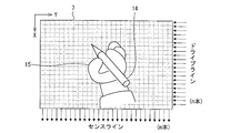
- FIG. 3 is a diagram illustrating a method for detecting a hand-held area according to the touch sensor system 1.
- a state is schematically shown in which a character is being written with the pen 14 while the hand 15 is touched on the touch panel 7 by the touch panel 7 having n drive lines and m sense lines.
- FIG. 4 is a flowchart showing the operation of the touch sensor system 1 according to the embodiment.
- the power supply of the touch panel system 1 shown in FIG. 1 is turned on (step S1).
- the parameters stored in the hand-held parameter storage unit 8 provided in the capacitance distribution detection circuit 18 of the touch panel system 1 are initialized (step S2).
- the touch panel 7 is driven by the driver 9 (step S3).
- the capacitance signal read from the touch panel 7 by the sense amplifier 10 is AD converted by the AD converter 12 (step S4).
- the capacitance distribution calculation unit 3 calculates the capacitance distribution of the touch panel 7 based on the capacitance signal AD-converted by the AD converter 12 (step S5).
- the handle removal processing unit 2 calculates a handle region based on the capacity distribution of the touch panel 7 calculated by the capacity distribution calculation unit 3 (step S6). Thereafter, the handle removal processing unit 2 sets a replacement area based on the calculated handle area, and replaces the capacitance value in the replacement area with zero (step S7).
- the touch recognition unit 4 obtains the coordinate value of the touch input based on the capacitance distribution of the touch panel 7 in which the capacitance value in the replacement area is replaced with zero (Step S8). Next, the touch recognition unit 4 outputs the coordinate value of the touch input to the host device 13 (step S9). Then, the process returns to step S3.
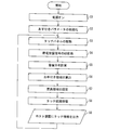
- FIG. 5 is a flowchart showing the operation of the manual removal processing unit 2. This flowchart corresponds to the detailed flowchart of steps S6 and S7 shown in FIG.
- m number of sense lines
- n number of drive lines
- PALM_MODE Hand pen mode flag
- 1 when on, 0 when off
- PEN_THRESH pen input threshold value for determining whether or not the touch input is performed by the pen
- FOOT_THRESH a peripheral threshold value for determining the magnitude of the capacitance signal value around the peak of the capacitance distribution map
- AREA_THRESH Area threshold value for determining the number of peripheral areas where the capacitance signal value exceeds the peripheral threshold value FOOT_THRESH around the peak of the capacitance distribution map
- C [j] [i] capacitance value at coordinates (i, j) (intensity of capacitance signal)
- Flag [j] [i] Flag for replacing the value of the capacitance signal in the capacitance distribution map with zero (hereinafter also referred to as “zero fill”), zero fill when 0, no zero fill when 1, count: a counter for counting
- FOOT_THRESH2 a second peripheral threshold value for determining the magnitude of the signal value around the peak of the capacity distribution map
- AREA_THRESH2 a second region threshold value for determining the number of peripheral regions around the mountain of the capacity distribution map whose signal value exceeds the second peripheral threshold value FOOT_THRESH2.
- the flowchart shown in FIG. 5 is for identifying and recognizing the touch of the pen and the touch of the finger, and removing the capacitance signal by the touch input to the hand-held area.
- the process for determining the touch of the pen is steps S14 to S16, and the process for determining the touch with the finger is steps S23 to S25.
- step S11 the detection unit 5 provided in the manual removal processing unit 2 is stored in the manual parameter storage unit 8.
- the flag Flag [j] [i] is initialized with 1.
- step S12 it is determined whether or not the capacitance value C [j] [i] of the touch panel 7 is larger than the pen input threshold PEN_THRESH.
- the capacitance value C [j] [i] of the touch panel 7 is larger than the intensity threshold value FINGER_THRESH in step S21. Determine whether it is larger.
- the counter count is initialized to 0 (step S13).
- step S14 j-dm1 ⁇ q ⁇ j + dp1 i-sm1 ⁇ p ⁇ i + sp1
- step S14 j-dm2 ⁇ q ⁇ j + dp2 i-sm2 ⁇ p ⁇ i + sp2
- step S14 j-dm2 ⁇ q ⁇ j + dp2 i-sm2 ⁇ p ⁇ i + sp2
- the processing in steps S14 to S16 is repeated for the next coordinates (p, q).
- step S15 it is determined whether or not the capacitance value C [q] [p] of the touch panel 7 is larger than the peripheral threshold FOOT_THRESH.
- the value of the counter count is increased by 1 in step S16.
- step S15 When it is determined that the capacitance value C [q] [p] is not larger than the peripheral threshold FOOT_THRESH (NO in step S15), the processes in steps S14 to S16 are repeated for the next coordinates (p, q). Regarding steps S14 to S16, j-dm1 ⁇ q ⁇ j + dp1 i-sm1 ⁇ p ⁇ i + sp1
- step S17 it is determined in step S17 whether the counter count is larger than the area threshold value AREA_THRESH.
- the flag Flag [j] [i] is set to 0 in step 18.
- step S21 When it is determined that the capacitance value C [j] [i] is larger than the intensity threshold FINGER_THRESH (YES in step S21), the counter count is initialized to 0 (step S22). j-dm1 ⁇ q ⁇ j + dp1 i-sm1 ⁇ p ⁇ i + sp1 The processing in steps S23 to S25 is repeated for coordinates (p, q) that satisfy the above.
- step S23 j-dm2 ⁇ q ⁇ j + dp2 i-sm2 ⁇ p ⁇ i + sp2 For the coordinates (p, q) determined to satisfy the above (YES in step S23), the processing in steps S23 to S25 is repeated for the next coordinates (p, q).
- step S24 it is determined in step S24 whether or not the capacitance value C [q] [p] of the touch panel 7 is larger than the second peripheral threshold value FOOT_THRESH2.
- step S24 When it is determined that the capacitance value C [q] [p] is larger than the second peripheral threshold FOOT_THRESH2 (YES in step S24), the value of the counter count is increased by 1 in step S25. When it is determined that the capacitance value C [q] [p] is not larger than the second peripheral threshold FOOT_THRESH2 (NO in step S24), the processing in steps S23 to S25 is performed on the next coordinates (p, q). repeat.
- step S26 If the repetition regarding the coordinates (p, q) satisfying is completed, it is determined in step S26 whether or not the counter count is larger than the second area threshold value AREA_THRESH2. When it is determined that the counter count is larger than the second area threshold value AREA_THRESH2 (YES in step S26), the flag Flag [j] [i] is set to 0 in step 27.
- steps S12 to S27 (excluding steps S19 and S20) is repeated as many times as it corresponds to the capacity distribution map C [j] [i] of n rows and m columns.
- the replacement unit 6 replaces the capacitance value C [j] [i] with zero for the coordinates where the flag Flag [j] [i] is zero (step S19).
- step S10 When it is determined that the variable PALM_MODE is not on (No in step S10) or when step S19 is executed, the manual removal processing unit 2 sends the replaced capacitance value C [j] [i] to the touch recognition unit 4. Transmit (step S20).
- variable PALM_MODE is a flag indicating whether or not the touch mode is set, and is stored in the touch parameter storage unit 8.
- PALM_MODE When PALM_MODE is on, the handling process shown in steps S11 to S27 described above is executed.
- the setting of the replacement area for the touch recognition unit 4 is not necessarily replaced by zero, and any method may be used as long as the touched area can be set as a non-detection area for touch recognition. Replace with a value.
- FIG. 6 shows the relationship between the coordinates (i, j) and the parameters described in steps S14 to S16 and steps S23 to 25 in order to facilitate understanding of the algorithm shown in FIG. .
- the detection region R1 that determines the strength of the capacitance signal to determine whether or not the touch input is performed by a finger has coordinates (i, j) and a plurality of surroundings that form a donut shape It is surrounded by the region R2.
- An intermediate region R3 is disposed between the detection region R1 and the plurality of peripheral regions R2.
- the coordinates of the detection region R1 are (i, j), and the coordinates of the upper left peripheral region R2 are (i-sm1, j-dm1).
- the coordinates of the lower left peripheral region R2 are (i + sp1, j ⁇ dm1)
- the coordinates of the upper right peripheral region R2 are (i ⁇ sm1, j + dp1)
- the coordinates of the lower right peripheral region R2 are (i + sp1, j + dp1). It is.
- the coordinates of the upper left intermediate region R3 are (i-sm2, j-dm2), and the coordinates of the lower left intermediate region R3 are (i + sp2, j-dm2).
- the coordinates of the upper right middle region R3 are (i ⁇ sm2, j + dp2), and the coordinates of the lower right middle region R3 are (i + sp2, j + dp2).
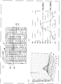
- FIG. 7A is an actual measurement example of a part of the capacity distribution map (around the pen touch position) when the touch panel is touched with a pen.
- This capacity distribution map is generated by the capacity distribution calculation unit 3 shown in FIG.
- the arrangement of the detection region R1, the peripheral region R2, and the intermediate region R3 shown in FIG. 7A is obtained when the coordinates of the detection region R1 are (i, j) and the parameters shown in FIG. 6 are set as follows. Corresponds to the arrangement.
- FIG. 7B is a three-dimensional graph of the capacity distribution map shown in FIG.
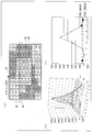
- FIGS. 8A, 8 ⁇ / b> B, and 8 ⁇ / b> C are a capacitance distribution map and its graph at the moment when the fist is brought into contact with the touch panel 7.
- the detection area R1 of the coordinates (i, j) is not touched by a pen but is determined to be a hand-held area, and C [j] [i] is zero-filled.
- FIGS. 9A, 9B, and 9C are a capacity distribution map and its graph in a state where the fist is in close contact with the touch panel.
- the coordinate (i, j) detection area R1 is not touch-inputted by the pen, but is determined to be a touch area, and C [j] [i ] Is zero-filled.
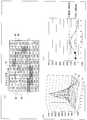
- FIG. 10A is an actual measurement example of a part of the capacity distribution map (around the position touched with the finger) when the touch panel is touched with the finger.
- This capacity distribution map is generated by the capacity distribution calculation unit 3 shown in FIG.
- FIG. 10A corresponds to the case where the coordinates corresponding to the detection region R1 are (i, j) and the parameters shown in FIG. 6 are set as follows.
- FIG. 10B is a three-dimensional graph of the capacity distribution map of FIG.
- FIG. 10C is a graph obtained by taking out the capacitance values in the region of the fourth row of the capacitance distribution map of FIG. This is an area in which it is determined whether or not the outer area of the rectangle composed of the 5-row and 4-column detection area R1 and the intermediate area R3 surrounded by the thick line in FIG. 10A is larger than the second peripheral threshold value FOOT_THRESH2. .
- FOOT_THRESH2 700 10A, as shown in FIG.
- FIGS. 11A, 11B, and 11C are a capacitance distribution map and a graph thereof in a state where the fist is in close contact with the touch panel.
- an area outside the rectangle including the detection area R1 and the intermediate area R3 of 5 rows and 4 columns surrounded by a thick line in FIG. Is a region in which it is determined whether or not is greater than the second peripheral threshold FOOT_THRESH2.
- the detection means includes a peripheral region in which the intensity of the capacitance signal in the detection region exceeds the intensity threshold, and the intensity of the capacitance signal exceeds the peripheral threshold. It is preferable that the detection area is determined as a hand-held area when the number exceeds the predetermined area threshold.
- an intermediate region is disposed between the detection region and the plurality of peripheral regions.
- the detection means detects the touched area based on a pen input threshold value for determining whether or not the touch input is performed by a pen.
- the present invention can be applied to a touch sensor system that detects pen input and finger input input to a touch panel having a plurality of capacitances arranged in a matrix.
Landscapes
- Engineering & Computer Science (AREA)
- General Engineering & Computer Science (AREA)
- Theoretical Computer Science (AREA)
- Human Computer Interaction (AREA)
- Physics & Mathematics (AREA)
- General Physics & Mathematics (AREA)
- Position Input By Displaying (AREA)
Abstract
タッチセンサシステムの検出部は、指によるタッチ入力か否かを判定するために検出領域(R1)における静電容量信号の強度を判定するための強度閾値と、検出領域(R1)を囲む複数の周辺領域(R2)における静電容量信号の強度を判定するために設けられて強度閾値よりも低い周辺閾値とに基づいてお手付き領域を検出する。
Description
本発明は、マトリックス状に配置された複数の静電容量を有するタッチパネルに入力されたペン入力および指入力を検出するタッチセンサシステムに関する。
複数の第1信号線と複数の第2信号線との交点にそれぞれ形成される複数の静電容量の値の分布を検出するタッチセンサシステムが特許文献1に開示されている。そして、従来の静電容量値の分布を検出するタッチセンサシステムにおいては、特許文献2に示すように、信号処理により、タッチパネルにタッチしている指及び手の部分の認識を試みていた。
図12は、特許文献3に開示された従来のタッチセンサシステム91の構成を示すブロック図である。タッチセンサシステム91は、タッチパネル93と静電容量値分布検出回路92とを備えている。タッチパネル93は、水平方向に沿って互いに平行に配置されたドライブラインHL1~HLnと、垂直方向に沿って互いに平行に配置されたセンスラインVL1~VLmと、ドライブラインHL1~HLnとセンスラインVL1~VLmとの交点にそれぞれ形成される複数の静電容量とを備えている。
静電容量値分布検出回路92は、ドライバ95を備えている。ドライバ95は、符号系列に基づいてドライブラインHL1~HLnに電圧を印加して各静電容量を駆動する。静電容量値分布検出回路92には、センスアンプ96が設けられている。センスアンプ96は、ドライバ95により駆動された各静電容量に対応する電圧の線形和を、センスラインVL1~VLmを通して読み出して、AD変換器98に供給する。AD変換器98は、センスラインVL1~VLmを通して読み出した各静電容量に対応する電圧の線形和をAD変換して容量分布計算部99に供給する。
容量分布計算部99は、AD変換器98から供給された各静電容量に対応する電圧の線形和と符号系列とに基づいて、タッチパネル93上の静電容量分布を計算してタッチ認識部90に供給する。タッチ認識部90は、容量分布計算部99から供給された静電容量分布に基づいて、タッチパネル93上のタッチされた位置を認識する。
静電容量値分布検出回路92は、タイミングジェネレータ97を有している。タイミングジェネレータ97は、ドライバ95の動作を規定する信号と、センスアンプ96の動作を規定する信号と、AD変換器98の動作を規定する信号とを生成して、ドライバ95、センスアンプ96、及びAD変換器98に供給する。
特許文献4には、マトリックス状に配置された複数の静電容量を有するタッチパネルにペン入力を行うために手を着いた領域を表すお手付き領域を、タッチセンサシステムに接続されたホスト装置に搭載されたアプリケーションソフトウェアから指定し、お手付き領域を示す枠を描画するとともに、タッチパネルにペン入力を行うために着いた手の移動に追随して、随時お手付き領域の位置を修正する構成が開示されている。
特許文献5は、マトリックス状に配置された複数の静電容量を有するタッチパネルにペン入力を行うために手を着いた領域を表すお手付き領域を、静電容量の変化を表す静電容量信号の強度に基づいて検出し、検出されたお手付き領域の中に配置された静電容量に対応する静電容量信号の値を、タッチ入力の無い状態を表す無値に置換する構成を開示している。
上記先行技術の中で、タッチパネルにペン入力を行うために手を着いた領域を表すお手付き領域を開示している先行技術は、上記特許文献4及び5である。特許文献4は、お手付き領域の指定、描画、及び位置の修正を教示しており、お手付き領域を検出する構成を開示しているのは特許文献5である。
この特許文献5に開示された構成では、タッチパネルコントローラにて、静電容量信号値の大きな領域をお手付き領域と判断し、タッチ入力の検知対象から除外することにより、お手付き領域へのタッチ入力による静電容量信号の除去を実現している。しかしながら、信号値の大きさのみで判断しているため、指によりタッチ入力された位置もお手付き領域と誤認識され、タッチ入力の検知対象から除去される。このため、指によるタッチ入力を検知することができず、タッチセンサシステムがペン入力専用の入力システムになってしまうという問題がある。
本発明の目的は、指入力に基づく静電容量信号が発生する検出領域をお手付き領域として誤認識するおそれを防止したタッチセンサシステムを提供することにある。
上記の課題を解決するために、本発明に係るタッチセンサシステムは、マトリックス状に配置された複数の静電容量を有するタッチパネルにタッチ入力を行うために手を着いた領域を表すお手付き領域を、前記静電容量の変化を表す静電容量信号に基づいて検出する検出手段と、前記検出手段により検出されたお手付き領域の中に配置された静電容量に対応する静電容量信号の値を、タッチ入力の無い状態を表す無値に置換する置換手段と、前記置換手段により無値に置換された静電容量信号と、前記お手付き領域の外に配置された静電容量に対応する静電容量信号とに基づいて、前記タッチ入力の座標値をホスト装置に出力するタッチ入力認識手段とを備え、前記検出手段は、指によるタッチ入力か否かを判定するために検出領域における前記静電容量信号の強度を判定するための強度閾値と、前記検出領域を囲む複数の周辺領域における前記静電容量信号の強度を判定するために設けられて前記強度閾値よりも低い周辺閾値とに基づいて前記お手付き領域を検出することを特徴とする。
この特徴により、指によるタッチ入力か否かを判定する強度閾値により検出領域における前記静電容量信号の強度を判定し、前記強度閾値よりも低い周辺閾値により前記検出領域を囲む複数の周辺領域における前記静電容量信号の強度を判定する。このため、指によるタッチ入力を超える検出領域を検知し、その周辺の静電容量分布の形状を調べ、検出領域の周辺の静電容量分布のすそ野が広がっている場合に、当該検出領域をお手付き領域と判断し、タッチ入力の無い状態を表す無値に置換することができる。この結果、指入力に基づく静電容量信号が発生する検出領域をお手付き領域として誤認識するおそれを防止したタッチセンサシステムを提供することができる。
本発明に係るタッチセンサシステムは、指によるタッチ入力か否かを判定するために検出領域における前記静電容量信号の強度を判定するための強度閾値と、前記検出領域を囲む複数の周辺領域における前記静電容量信号の強度を判定するために設けられて前記強度閾値よりも低い周辺閾値とに基づいて前記お手付き領域を検出する。
この結果、指入力に基づく静電容量信号が発生する検出領域をお手付き領域として誤認識するおそれを防止したタッチセンサシステムを提供することができる。
以下、本発明に係る実施の形態のタッチセンサシステムについて、詳細に説明する。
(タッチセンサシステム1の構成)
図1は、実施の形態1に係るタッチセンサシステム1の構成を示すブロック図である。タッチセンサシステム1は、タッチパネル7と静電容量値分布検出回路18とを備えている。タッチパネル7は、水平方向に沿って互いに平行に配置されたドライブラインHL1~HLnと、垂直方向に沿って互いに平行に配置されたセンスラインVL1~VLmと、ドライブラインHL1~HLnとセンスラインVL1~VLmとの交点にそれぞれ形成される複数の静電容量とを備えている。
図1は、実施の形態1に係るタッチセンサシステム1の構成を示すブロック図である。タッチセンサシステム1は、タッチパネル7と静電容量値分布検出回路18とを備えている。タッチパネル7は、水平方向に沿って互いに平行に配置されたドライブラインHL1~HLnと、垂直方向に沿って互いに平行に配置されたセンスラインVL1~VLmと、ドライブラインHL1~HLnとセンスラインVL1~VLmとの交点にそれぞれ形成される複数の静電容量とを備えている。
静電容量値分布検出回路18は、ドライバ9を備えている。ドライバ9は、符号系列に基づいてドライブラインHL1~HLnに電圧を印加して各静電容量を駆動する。静電容量値分布検出回路18には、センスアンプ10が設けられている。センスアンプ10は、ドライバ9により駆動された各静電容量に対応する電圧の線形和を、センスラインVL1~VLmを通して読み出して、AD変換器12に供給する。AD変換器12は、センスラインVL1~VLmを通して読み出した各静電容量に対応する電圧の線形和をAD変換して容量分布計算部3に供給する。
容量分布計算部3は、AD変換器12から供給された各静電容量に対応する電圧の線形和と符号系列とに基づいて、タッチパネル7上の静電容量分布を計算してお手付き除去処理部2に供給する。
図2は、タッチセンサシステム1に設けられたお手付き除去処理部2の構成を示すブロック図である。お手付き除去処理部2は、検出部5と置換部6とを有している。検出部5は、マトリックス状に配置された複数の静電容量を有するタッチパネル7にペン入力または指による入力を行うために手を着いた領域を表すお手付き領域を、静電容量の変化を表す静電容量信号、及びお手付きパラメータ記憶部8に記憶されたパラメータに基づいて検出する。
検出部5は、指によるタッチ入力か否かを判定するために検出領域における静電容量信号の強度を判定するための強度閾値と、検出領域を囲む複数の周辺領域における静電容量信号の強度を判定するために設けられて強度閾値よりも低い周辺閾値とに基づいてお手付き領域を検出する。
検出部6は、検出領域における静電容量信号の強度が強度閾値を超えており、静電容量信号の強度が周辺閾値を超えている周辺領域の数が予め定められた領域閾値を超えているときに、この検出領域をお手付き領域と判断する。
検出部5は、ペンによるタッチ入力か否かを判定するためのペン入力閾値と周辺閾値とに基づいてお手付き領域を検出してもよい。
置換部6は、検出部5により検出されたお手付き領域の中に配置された静電容量に対応する静電容量信号の値を、タッチ入力の無い状態を表す無値に置換してタッチ認識部4(図1)に供給する。
タッチ認識部4は、置換部6により無値に置換された静電容量信号と、お手付き領域の外に配置された静電容量に対応する静電容量信号とに基づいて、ペン入力または指による入力の座標値を、タッチセンサシステム1の外部に接続されたホスト装置13に出力する。ホスト装置13は、タッチ認識部4から供給されたタッチ入力の座標値に基づいて、アプリケーションソフトでの処理を実行する。
静電容量値分布検出回路18は、タイミングジェネレータ11を有している。タイミングジェネレータ11は、ドライバ9の動作を規定する信号と、センスアンプ10の動作を規定する信号と、AD変換器12の動作を規定する信号とを生成して、ドライバ9、センスアンプ10、及びAD変換器12に供給する。
図3は、タッチセンサシステム1に係るお手付き領域の検知方法を示す図である。ドライブラインn本、センスラインm本のタッチパネル7で手15をタッチパネル7にお手付きしながらペン14で字を書いている様子を模式的に示している。
(タッチセンサシステム1の動作)
図4は、実施の形態に係るタッチセンサシステム1の動作を示すフローチャートである。まず、図1に示すタッチパネルシステム1の電源をオンする(ステップS1)。そして、タッチパネルシステム1の静電容量分布検出回路18に設けられたお手付きパラメータ記憶部8に格納されたパラメータを初期化する(ステップS2)。次に、ドライバ9によりタッチパネル7を駆動する(ステップS3)。その後、センスアンプ10によりタッチパネル7から読み出した静電容量信号をAD変換器12によりAD変換する(ステップS4)。
図4は、実施の形態に係るタッチセンサシステム1の動作を示すフローチャートである。まず、図1に示すタッチパネルシステム1の電源をオンする(ステップS1)。そして、タッチパネルシステム1の静電容量分布検出回路18に設けられたお手付きパラメータ記憶部8に格納されたパラメータを初期化する(ステップS2)。次に、ドライバ9によりタッチパネル7を駆動する(ステップS3)。その後、センスアンプ10によりタッチパネル7から読み出した静電容量信号をAD変換器12によりAD変換する(ステップS4)。
そして、容量分布計算部3は、AD変換器12によりAD変換された静電容量信号に基づいて、タッチパネル7の容量分布を計算する(ステップS5)。次に、お手付き除去処理部2は、容量分布計算部3により計算されたタッチパネル7の容量分布に基づいて、お手付き領域を算出する(ステップS6)。その後、お手付き除去処理部2は、算出したお手付き領域に基づいて置換領域を設定し、置換領域内の容量値をゼロで置き換える(ステップS7)。
そして、タッチ認識部4は、置換領域内の容量値をゼロで置き換えたタッチパネル7の容量分布に基づいて、タッチ入力の座標値を求める(ステップS8)。次に、タッチ認識部4は、タッチ入力の座標値をホスト装置13に出力する(ステップS9)。そして、ステップS3に戻る。
(お手付き領域の検出動作)
図5は、お手付き除去処理部2の動作を示すフローチャートである。このフローチャートは、図4に示すステップS6及びS7の詳細なフローチャートに相当する。
図5は、お手付き除去処理部2の動作を示すフローチャートである。このフローチャートは、図4に示すステップS6及びS7の詳細なフローチャートに相当する。
まず、フローチャートの説明で使用するパラメータの意義は、以下に示すとおりである。
m:センスライン数、
n:ドライブライン数、
PALM_MODE:お手付きペンモードフラグ、オンのとき1、オフのときは0、
PEN_THRESH:ペンによるタッチ入力か否かを判断するためのペン入力閾値、
FOOT_THRESH:容量分布マップの山の周辺の静電容量信号値の大きさを判断するための周辺閾値、
AREA_THRESH:容量分布マップの山の周辺で静電容量信号値が周辺閾値FOOT_THRESHを超えた周辺領域の数を判断するための領域閾値、
C[j][i]:座標(i、j)における容量値(静電容量信号の強度)、
Flag[j][i]:容量分布マップにおける静電容量信号の値をゼロで置き換える(以下、「ゼロフィル」とも表記する)ためのフラグ、0のときゼロフィルする、1のときゼロフィルしない、
count:座標(p,q)の容量値C[q][p]が周辺閾値FOOT_THRESHを超える周辺領域の個数を数えるためのカウンタ、
FINGER_THRESH:指によるタッチ入力か否かを判断するための強度閾値、
FOOT_THRESH2:容量分布マップの山の周辺の信号値の大きさを判断するための第2の周辺閾値、
AREA_THRESH2:容量分布マップの山の周辺で信号値が第2の周辺閾値FOOT_THRESH2を超えた周辺領域の数を判断するための第2の領域閾値、
とする。
m:センスライン数、
n:ドライブライン数、
PALM_MODE:お手付きペンモードフラグ、オンのとき1、オフのときは0、
PEN_THRESH:ペンによるタッチ入力か否かを判断するためのペン入力閾値、
FOOT_THRESH:容量分布マップの山の周辺の静電容量信号値の大きさを判断するための周辺閾値、
AREA_THRESH:容量分布マップの山の周辺で静電容量信号値が周辺閾値FOOT_THRESHを超えた周辺領域の数を判断するための領域閾値、
C[j][i]:座標(i、j)における容量値(静電容量信号の強度)、
Flag[j][i]:容量分布マップにおける静電容量信号の値をゼロで置き換える(以下、「ゼロフィル」とも表記する)ためのフラグ、0のときゼロフィルする、1のときゼロフィルしない、
count:座標(p,q)の容量値C[q][p]が周辺閾値FOOT_THRESHを超える周辺領域の個数を数えるためのカウンタ、
FINGER_THRESH:指によるタッチ入力か否かを判断するための強度閾値、
FOOT_THRESH2:容量分布マップの山の周辺の信号値の大きさを判断するための第2の周辺閾値、
AREA_THRESH2:容量分布マップの山の周辺で信号値が第2の周辺閾値FOOT_THRESH2を超えた周辺領域の数を判断するための第2の領域閾値、
とする。
図5に示すフローチャートは、ペンのタッチと指のタッチとを識別して認識し、お手付き領域へのタッチ入力による静電容量信号の除去を行うものである。ペンのタッチの判断を行う処理は、ステップS14~S16であり、指によるタッチの判断を行う処理は、ステップS23~S25である。
まず、ステップS10で、変数PALM_MODEがオンであると判定したとき(ステップS10でYes)、ステップS11では、お手付き除去処理部2に設けられた検出部5が、お手付きパラメータ記憶部8に記憶されたフラグFlag[j][i]を1で初期化する。さらに、ステップS12でタッチパネル7の容量値C[j][i]がペン入力閾値PEN_THRESHよりも大きいか否かを判定する。容量値C[j][i]がペン入力閾値PEN_THRESHよりも大きいと判定したときは(ステップS12でYES)、ステップS21でタッチパネル7の容量値C[j][i]が強度閾値FINGER_THRESHよりも大きいか否かを判定する。
容量値C[j][i]が強度閾値FINGER_THRESHよりも大きくないと判定したときは(ステップS21でNO)、カウンタcountを0に初期化する(ステップS13)。
そして、
j - dm1 ≦ q ≦ j + dp1
i - sm1 ≦ p ≦ i + sp1
を満たす座標(p、q)について、ステップS14~S16の処理を繰り返す。
ステップS14にて、
j - dm2 ≦ q ≦ j + dp2
i - sm2 ≦ p ≦ i + sp2
を満足すると判断した座標(p、q)については(ステップS14でYES)、次の座標(p、q)に対してステップS14~S16の処理を繰り返す。
ステップS14にて、
j - dm2 ≦ q ≦ j + dp2
i - sm2 ≦ p ≦ i + sp2
を満足しないと判断した座標(p、q)については(ステップS14でNO)、ステップS15でタッチパネル7の容量値C[q][p]が周辺閾値FOOT_THRESHよりも大きいか否かを判定する。容量値C[q][p]が周辺閾値FOOT_THRESHよりも大きいと判定したときは(ステップS15でYES)、ステップS16でカウンタcountの値を1だけ増加させる。容量値C[q][p]が周辺閾値FOOT_THRESHよりも大きくないと判定したときは(ステップS15でNO)、次の座標(p、q)に対してステップS14~S16の処理を繰り返す。
ステップS14~S16に関して、
j - dm1 ≦ q ≦ j + dp1
i - sm1 ≦ p ≦ i + sp1
を満たす座標(p、q)に関する上記処理の繰り返しが終了すれば、ステップS17でカウンタcountが領域閾値AREA_THRESHよりも大きいか否かを判定する。カウンタcountが領域閾値AREA_THRESHよりも大きいと判定したときは(ステップS17でYES)、ステップ18でフラグFlag[j][i]を0にする。
j - dm1 ≦ q ≦ j + dp1
i - sm1 ≦ p ≦ i + sp1
を満たす座標(p、q)について、ステップS14~S16の処理を繰り返す。
ステップS14にて、
j - dm2 ≦ q ≦ j + dp2
i - sm2 ≦ p ≦ i + sp2
を満足すると判断した座標(p、q)については(ステップS14でYES)、次の座標(p、q)に対してステップS14~S16の処理を繰り返す。
ステップS14にて、
j - dm2 ≦ q ≦ j + dp2
i - sm2 ≦ p ≦ i + sp2
を満足しないと判断した座標(p、q)については(ステップS14でNO)、ステップS15でタッチパネル7の容量値C[q][p]が周辺閾値FOOT_THRESHよりも大きいか否かを判定する。容量値C[q][p]が周辺閾値FOOT_THRESHよりも大きいと判定したときは(ステップS15でYES)、ステップS16でカウンタcountの値を1だけ増加させる。容量値C[q][p]が周辺閾値FOOT_THRESHよりも大きくないと判定したときは(ステップS15でNO)、次の座標(p、q)に対してステップS14~S16の処理を繰り返す。
ステップS14~S16に関して、
j - dm1 ≦ q ≦ j + dp1
i - sm1 ≦ p ≦ i + sp1
を満たす座標(p、q)に関する上記処理の繰り返しが終了すれば、ステップS17でカウンタcountが領域閾値AREA_THRESHよりも大きいか否かを判定する。カウンタcountが領域閾値AREA_THRESHよりも大きいと判定したときは(ステップS17でYES)、ステップ18でフラグFlag[j][i]を0にする。
容量値C[j][i]が強度閾値FINGER_THRESHよりも大きいと判定したときは(ステップS21でYES)、カウンタcountを0に初期化し(ステップS22)、
j - dm1 ≦ q ≦ j + dp1
i - sm1 ≦ p ≦ i + sp1
を満たす座標(p、q)について、ステップS23~S25の処理を繰り返す。
ステップS23にて、
j - dm2 ≦ q ≦ j + dp2
i - sm2 ≦ p ≦ i + sp2
を満足すると判断した座標(p、q)については(ステップS23でYES)、次の座標(p、q)に対してステップS23~S25の処理を繰り返す。
ステップS23にて、
j - dm2 ≦ q ≦ j + dp2
i - sm2 ≦ p ≦ i + sp2
を満足しないと判断した座標(p、q)については(ステップS23でNO)、ステップS24でタッチパネル7の容量値C[q][p]が第2の周辺閾値FOOT_THRESH2よりも大きいか否かを判定する。容量値C[q][p]が第2の周辺閾値FOOT_THRESH2よりも大きいと判定したときは(ステップS24でYES)、ステップS25でカウンタcountの値を1だけ増加させる。容量値C[q][p]が第2の周辺閾値FOOT_THRESH2よりも大きくないと判定したときは(ステップS24でNO)、次の座標(p、q)に対してステップS23~S25の処理を繰り返す。
ステップS23~S25に関して、
j - dm1 ≦ q ≦ j + dp1
i - sm1 ≦ p ≦ i + sp1
を満たす座標(p、q)に関する繰り返しが終了すれば、ステップS26でカウンタcountが第2の領域閾値AREA_THRESH2よりも大きいか否かを判定する。カウンタcountが第2の領域閾値AREA_THRESH2よりも大きいと判定したときは(ステップS26でYES)、ステップ27でフラグFlag[j][i]を0にする。
j - dm1 ≦ q ≦ j + dp1
i - sm1 ≦ p ≦ i + sp1
を満たす座標(p、q)について、ステップS23~S25の処理を繰り返す。
ステップS23にて、
j - dm2 ≦ q ≦ j + dp2
i - sm2 ≦ p ≦ i + sp2
を満足すると判断した座標(p、q)については(ステップS23でYES)、次の座標(p、q)に対してステップS23~S25の処理を繰り返す。
ステップS23にて、
j - dm2 ≦ q ≦ j + dp2
i - sm2 ≦ p ≦ i + sp2
を満足しないと判断した座標(p、q)については(ステップS23でNO)、ステップS24でタッチパネル7の容量値C[q][p]が第2の周辺閾値FOOT_THRESH2よりも大きいか否かを判定する。容量値C[q][p]が第2の周辺閾値FOOT_THRESH2よりも大きいと判定したときは(ステップS24でYES)、ステップS25でカウンタcountの値を1だけ増加させる。容量値C[q][p]が第2の周辺閾値FOOT_THRESH2よりも大きくないと判定したときは(ステップS24でNO)、次の座標(p、q)に対してステップS23~S25の処理を繰り返す。
ステップS23~S25に関して、
j - dm1 ≦ q ≦ j + dp1
i - sm1 ≦ p ≦ i + sp1
を満たす座標(p、q)に関する繰り返しが終了すれば、ステップS26でカウンタcountが第2の領域閾値AREA_THRESH2よりも大きいか否かを判定する。カウンタcountが第2の領域閾値AREA_THRESH2よりも大きいと判定したときは(ステップS26でYES)、ステップ27でフラグFlag[j][i]を0にする。
このステップS12~S27(ステップS19、S20を除く)の処理を、n行m列の容量分布マップC[j][i]のそれぞれに対応するだけの回数分繰り返す。繰り返しが終了した後、置換部6は、フラグFlag[j][i]がゼロである座標に対して、容量値C[j][i]をゼロにより置換する(ステップS19)。
タッチ認識部4に対する置換領域の設定もゼロにより置換する必然性はなく、お手付き領域をタッチ認識の非検知領域に設定できるのであれば、任意の方法でよく、タッチ入力の無い状態を表す無値で置換すればよい。
変数PALM_MODEがオンでないと判定したとき(ステップS10でNo)、またはステップS19を実行したときは、お手付き除去処理部2は、置換後の容量値C[j][i]をタッチ認識部4に送信する(ステップS20)。
変数PALM_MODEは、お手付きモードかどうかを示すフラグであり、お手付きパラメータ記憶部8に記憶されている。PALM_MODEがオンの場合、上述したステップS11~S27に示すお手付き対応処理が実行される。
また、タッチ認識部4に対する置換領域の設定もゼロにより置換する必然性はなく、お手付き領域をタッチ認識の非検知領域に設定できるのであれば、任意の方法でよく、タッチ入力の無い状態を表す無値で置換すればよい。
(検出領域R1、周辺領域R2、及び中間領域R3の関係)
図6は、図5に示すアルゴリズムを理解し易くするために、座標(i、j)とステップS14~S16、ステップS23~25の処理で記載したパラメータとの間の関係を示したものである。
図6は、図5に示すアルゴリズムを理解し易くするために、座標(i、j)とステップS14~S16、ステップS23~25の処理で記載したパラメータとの間の関係を示したものである。
指によるタッチ入力か否かを判定するために静電容量信号の強度を判定する検出領域R1は、座標(i、j)を有しており、ドーナッツ状の形状を構成している複数の周辺領域R2によって囲まれている。検出領域R1と複数の周辺領域R2との間に中間領域R3が配置されている。
前述したように検出領域R1の座標は(i、j)であり、左上の周辺領域R2の座標は(i-sm1、j-dm1)である。左下の周辺領域R2の座標は(i+sp1、j-dm1)であり、右上の周辺領域R2の座標は(i-sm1、j+dp1)であり、右下の周辺領域R2の座標は(i+sp1、j+dp1)である。
左上の中間領域R3の座標は(i-sm2、j-dm2)であり、左下の中間領域R3の座標は(i+sp2、j-dm2)である。右上の中間領域R3の座標は(i-sm2、j+dp2)であり、右下の中間領域R3の座標は(i+sp2、j+dp2)である。
(ペンによるタッチ入力に関する判断)
図7(a)は、ペンでタッチパネルをタッチしている場合の容量分布マップの一部(ペンタッチ位置の周辺)の実測例である。この容量分布マップは図1に示す容量分布計算部3にて生成される。ペンタッチの位置は容量分布マップを左上から右方向に順次スキャンし、容量値がペン入力閾値PEN_THRESH=400よりも大きくなる位置は、第4行第4列の「432」と表記された検出領域R1である。図7(a)に示す検出領域R1、周辺領域R2、及び中間領域R3の配置は、検出領域R1の座標を(i、j)とし、図6に示すパラメータを以下のように設定した場合の配置に相当する。
図7(a)は、ペンでタッチパネルをタッチしている場合の容量分布マップの一部(ペンタッチ位置の周辺)の実測例である。この容量分布マップは図1に示す容量分布計算部3にて生成される。ペンタッチの位置は容量分布マップを左上から右方向に順次スキャンし、容量値がペン入力閾値PEN_THRESH=400よりも大きくなる位置は、第4行第4列の「432」と表記された検出領域R1である。図7(a)に示す検出領域R1、周辺領域R2、及び中間領域R3の配置は、検出領域R1の座標を(i、j)とし、図6に示すパラメータを以下のように設定した場合の配置に相当する。
sm1=3、
sp1=6、
dm1=3、
dp1=4、
sm2=1、
sp2=3、
dm2=1、
dp2=2、
図7(b)は、図7(a)に示す容量分布マップを3次元グラフ化したものである。また、図7(c)は、図7(a)の容量分布マップの第4行を取り出してグラフ化したものである。図7(a)の太線で囲んだ5行4列の検出領域R1及び中間領域R3を含む矩形領域の外側の領域(複数の周辺領域R2)が、周辺閾値FOOT_THRESHよりも大きいか否かを判定している領域である。
たとえば、
周辺閾値FOOT_THRESH=100
に設定した場合、図7(a)に示すように、静電容量信号値が周辺閾値FOOT_THRESHよりも大きくなる座標を有する周辺領域R2は存在しない。このため、カウンタcountは0である。従って、たとえば、
領域閾値AREA_THRESH=3
に設定した場合、
count > AREA_THRESH
とはならない。このため、フラグFlag[j][i]は1のまま変更されない。従って、座標(i、j)はペンによるタッチ入力と判断され、C[j][i]をゼロフィルすることはない。
sp1=6、
dm1=3、
dp1=4、
sm2=1、
sp2=3、
dm2=1、
dp2=2、
図7(b)は、図7(a)に示す容量分布マップを3次元グラフ化したものである。また、図7(c)は、図7(a)の容量分布マップの第4行を取り出してグラフ化したものである。図7(a)の太線で囲んだ5行4列の検出領域R1及び中間領域R3を含む矩形領域の外側の領域(複数の周辺領域R2)が、周辺閾値FOOT_THRESHよりも大きいか否かを判定している領域である。
たとえば、
周辺閾値FOOT_THRESH=100
に設定した場合、図7(a)に示すように、静電容量信号値が周辺閾値FOOT_THRESHよりも大きくなる座標を有する周辺領域R2は存在しない。このため、カウンタcountは0である。従って、たとえば、
領域閾値AREA_THRESH=3
に設定した場合、
count > AREA_THRESH
とはならない。このため、フラグFlag[j][i]は1のまま変更されない。従って、座標(i、j)はペンによるタッチ入力と判断され、C[j][i]をゼロフィルすることはない。
同様に、図8(a)(b)(c)は、握りこぶしをタッチパネル7に接触させる瞬間の容量分布マップとそのグラフである。上述した図7に示すペンタッチの場合のパラメータと同じ値をパラメータに設定した場合、図8(a)の太線で囲んだ5行4列の矩形の外側の複数の周辺領域R2が、周辺閾値FOOT_THRESHよりも大きいか否かを判定している領域である。この領域内で周辺閾値FOOT_TRESH=100を超える静電容量信号値を有する周辺領域R2は、図8(a)で斜線で示すように、23個存在する。このため、カウンタcount=23となる。この場合、領域閾値AREA_THRESH=3に設定すると、
count > AREA_THRESH
を満たす。このため、Flag[j][i]は0に変更される。従って、座標(i、j)の検出領域R1は、ペンによるタッチ入力が行われているのでなく、お手付き領域であると判断され、C[j][i]はゼロフィルされる。検出領域R1は、スキャン中に、容量値がペン入力閾値PEN_THRESH=400よりも大きくなる位置である。
count > AREA_THRESH
を満たす。このため、Flag[j][i]は0に変更される。従って、座標(i、j)の検出領域R1は、ペンによるタッチ入力が行われているのでなく、お手付き領域であると判断され、C[j][i]はゼロフィルされる。検出領域R1は、スキャン中に、容量値がペン入力閾値PEN_THRESH=400よりも大きくなる位置である。
また、図9(a)(b)(c)は、握りこぶしをタッチパネルに密着させた状態での容量分布マップとそのグラフである。検出領域R1は、スキャン中に、容量値がペン入力閾値PEN_THRESH=400よりも大きくなる位置である。この場合も図8に示す例と同様に、座標(i、j)の検出領域R1は、ペンによるタッチ入力が行われているのでなく、お手付き領域であると判断され、C[j][i]はゼロフィルされる。
(指によるタッチ入力に関する判断)
図10(a)は、指でタッチパネルをタッチしている場合の容量分布マップの一部(指でタッチした位置の周辺)の実測例である。この容量分布マップは図1に示す容量分布計算部3にて生成される。指によるタッチの位置は容量分布マップを左上から右方向に順次スキャンする。このスキャン中に、容量値が強度閾値FINGER_THRESH=2500よりも大きくなる位置は、4行4列で静電容量信号値「4177」が表記されている検出領域R1である。図10(a)は、この検出領域R1に対応する座標を(i、j)とし、図6に示すパラメータを以下のように設定した場合に相当する。
図10(a)は、指でタッチパネルをタッチしている場合の容量分布マップの一部(指でタッチした位置の周辺)の実測例である。この容量分布マップは図1に示す容量分布計算部3にて生成される。指によるタッチの位置は容量分布マップを左上から右方向に順次スキャンする。このスキャン中に、容量値が強度閾値FINGER_THRESH=2500よりも大きくなる位置は、4行4列で静電容量信号値「4177」が表記されている検出領域R1である。図10(a)は、この検出領域R1に対応する座標を(i、j)とし、図6に示すパラメータを以下のように設定した場合に相当する。
sm1=3
sp1=6
dm1=3
dp1=4
sm2=1
sp2=3
dm2=1
dp2=2
図10(b)は、図10(a)の容量分布マップを3次元グラフ化したものである。また、図10(c)は、図10(a)の容量分布マップの第4行の領域の静電容量値を取り出してグラフ化したものである。図10(a)の太線で囲んだ5行4列の検出領域R1及び中間領域R3からなる矩形の外側の領域が第2の周辺閾値FOOT_THRESH2よりも大きいか否かを判定している領域である。
たとえば、
FOOT_THRESH2=700
に設定した場合、図10(a)に示すように、上記矩形の外側の領域において、静電容量信号値が第2の周辺閾値FOOT_THRESH2よりも大きくなる領域は存在しない。このため、カウンタcountは0である。従って、たとえば、
AREA_THRESH2=3
に設定した場合、
count > AREA_THRESH2
とはならず、Flag[j][i]は1のまま変更されない。従って、座標(i,j)は指によるタッチ入力であってお手付き領域でないと判断され、C[j][i]をゼロフィルすることはない。
sp1=6
dm1=3
dp1=4
sm2=1
sp2=3
dm2=1
dp2=2
図10(b)は、図10(a)の容量分布マップを3次元グラフ化したものである。また、図10(c)は、図10(a)の容量分布マップの第4行の領域の静電容量値を取り出してグラフ化したものである。図10(a)の太線で囲んだ5行4列の検出領域R1及び中間領域R3からなる矩形の外側の領域が第2の周辺閾値FOOT_THRESH2よりも大きいか否かを判定している領域である。
たとえば、
FOOT_THRESH2=700
に設定した場合、図10(a)に示すように、上記矩形の外側の領域において、静電容量信号値が第2の周辺閾値FOOT_THRESH2よりも大きくなる領域は存在しない。このため、カウンタcountは0である。従って、たとえば、
AREA_THRESH2=3
に設定した場合、
count > AREA_THRESH2
とはならず、Flag[j][i]は1のまま変更されない。従って、座標(i,j)は指によるタッチ入力であってお手付き領域でないと判断され、C[j][i]をゼロフィルすることはない。
同様に、図11(a)(b)(c)は、握りこぶしをタッチパネルに密着させた状態での容量分布マップとそのグラフである。上述の図10の指タッチの場合のパラメータと同じ値をパラメータに設定した場合、図11(a)の太線で囲んだ5行4列の検出領域R1及び中間領域R3からなる矩形の外側の領域が第2の周辺閾値FOOT_THRESH2よりも大きいか否かを判定している領域である。この領域内で第2の周辺閾値FOOT_TRESH2=700を超える周辺領域R2は、図11(a)に示すように8個あり、カウンタcount=8となる。この場合、第2の領域閾値AREA_THRESH2=3に設定した場合、
count > AREA_THRESH2
を満たす。このため、フラグFlag[j][i]は0に変更される。従って、座標(i,j)の検出領域R1は、指によるタッチ入力が行われたのでなく、お手付き領域であると判定され、C[j][i]はゼロフィルされる。
count > AREA_THRESH2
を満たす。このため、フラグFlag[j][i]は0に変更される。従って、座標(i,j)の検出領域R1は、指によるタッチ入力が行われたのでなく、お手付き領域であると判定され、C[j][i]はゼロフィルされる。
(適用範囲)
なお、本実施の形態では、静電容量型のタッチセンサシステムの例を示した。しかしながら、本発明はこれに限定されない。静電容量型以外のタッチセンサシステムに対しても本発明を適用することができる。例えば、電磁誘導型のタッチセンサシステムに対しても本発明を適用することができる。
なお、本実施の形態では、静電容量型のタッチセンサシステムの例を示した。しかしながら、本発明はこれに限定されない。静電容量型以外のタッチセンサシステムに対しても本発明を適用することができる。例えば、電磁誘導型のタッチセンサシステムに対しても本発明を適用することができる。
(本発明の他の表現)
本発明に係るタッチセンサシステムは、前記検出手段は、前記検出領域における静電容量信号の強度が前記強度閾値を超えており、前記静電容量信号の強度が前記周辺閾値を超えている周辺領域の数が予め定められた領域閾値を超えているときに、前記検出領域をお手付き領域と判断することが好ましい。
本発明に係るタッチセンサシステムは、前記検出手段は、前記検出領域における静電容量信号の強度が前記強度閾値を超えており、前記静電容量信号の強度が前記周辺閾値を超えている周辺領域の数が予め定められた領域閾値を超えているときに、前記検出領域をお手付き領域と判断することが好ましい。
上記構成により、簡単なアルゴリズムで検出領域の周辺の静電容量分布のすそ野の広がりを判定することができる。
本発明に係るタッチセンサシステムは、前記検出領域と前記複数の周辺領域との間に中間領域が配置されていることが好ましい。
上記構成により、検出領域の周辺の静電容量分布のすそ野の広がりを効率よく判定することができる。
本発明に係るタッチセンサシステムは、前記検出手段は、ペンによるタッチ入力か否かを判定するためのペン入力閾値に基づいて前記お手付き領域を検出することが好ましい。
上記構成により、ペン入力に基づく静電容量信号の検出領域をお手付き領域として誤認識するおそれを防止することができる。
本発明は上述した各実施形態に限定されるものではなく、請求項に示した範囲で種々の変更が可能であり、異なる実施形態にそれぞれ開示された技術的手段を適宜組み合わせて得られる実施形態についても本発明の技術的範囲に含まれる。
本発明は、マトリックス状に配置された複数の静電容量を有するタッチパネルに入力されたペンおよび指入力を検出するタッチセンサシステムに適用することができる。
1 タッチセンサシステム
2 お手付き除去処理部
3 容量分布計算部
4 タッチ認識部(ペン入力認識手段)
5 検出部(検出手段)
6 置換部(置換手段)
7 タッチパネル
8 お手付きパラメータ記憶部
9 ドライバ
10 センスアンプ
11 タイミングジェネレータ
12 AD変換器
13 ホスト装置
14 ペン
15 手
18 静電容量値分布検出回路
R1 検出領域
R2 周辺領域
R3 中間領域
2 お手付き除去処理部
3 容量分布計算部
4 タッチ認識部(ペン入力認識手段)
5 検出部(検出手段)
6 置換部(置換手段)
7 タッチパネル
8 お手付きパラメータ記憶部
9 ドライバ
10 センスアンプ
11 タイミングジェネレータ
12 AD変換器
13 ホスト装置
14 ペン
15 手
18 静電容量値分布検出回路
R1 検出領域
R2 周辺領域
R3 中間領域
Claims (4)
- マトリックス状に配置された複数の静電容量を有するタッチパネルにタッチ入力を行うために手を着いた領域を表すお手付き領域を、前記静電容量の変化を表す静電容量信号に基づいて検出する検出手段と、
前記検出手段により検出されたお手付き領域の中に配置された静電容量に対応する静電容量信号の値を、タッチ入力の無い状態を表す無値に置換する置換手段と、
前記置換手段により無値に置換された静電容量信号と、前記お手付き領域の外に配置された静電容量に対応する静電容量信号とに基づいて、前記タッチ入力の座標値をホスト装置に出力するタッチ入力認識手段とを備え、
前記検出手段は、指によるタッチ入力か否かを判定するために検出領域における前記静電容量信号の強度を判定するための強度閾値と、前記検出領域を囲む複数の周辺領域における前記静電容量信号の強度を判定するために設けられて前記強度閾値よりも低い周辺閾値とに基づいて前記お手付き領域を検出することを特徴とするタッチセンサシステム。 - 前記検出手段は、前記検出領域における静電容量信号の強度が前記強度閾値を超えており、前記静電容量信号の強度が前記周辺閾値を超えている周辺領域の数が予め定められた領域閾値を超えているときに、前記検出領域をお手付き領域と判断する請求項1に記載のタッチセンサシステム。
- 前記検出領域と前記複数の周辺領域との間に中間領域が配置されている請求項1に記載のタッチセンサシステム。
- 前記検出手段は、ペンによるタッチ入力か否かを判定するためのペン入力閾値に基づいて前記お手付き領域を検出する請求項1に記載のタッチセンサシステム。
Applications Claiming Priority (2)
| Application Number | Priority Date | Filing Date | Title |
|---|---|---|---|
| JP2012-122743 | 2012-05-30 | ||
| JP2012122743A JP5886139B2 (ja) | 2012-05-30 | 2012-05-30 | タッチセンサシステム |
Publications (1)
| Publication Number | Publication Date |
|---|---|
| WO2013179474A1 true WO2013179474A1 (ja) | 2013-12-05 |
Family
ID=49669616
Family Applications (1)
| Application Number | Title | Priority Date | Filing Date |
|---|---|---|---|
| PCT/JP2012/064240 Ceased WO2013179474A1 (ja) | 2012-05-30 | 2012-05-31 | タッチセンサシステム |
Country Status (4)
| Country | Link |
|---|---|
| US (1) | US8937609B2 (ja) |
| JP (1) | JP5886139B2 (ja) |
| TW (1) | TWI553533B (ja) |
| WO (1) | WO2013179474A1 (ja) |
Families Citing this family (16)
| Publication number | Priority date | Publication date | Assignee | Title |
|---|---|---|---|---|
| JP5973072B2 (ja) * | 2013-06-20 | 2016-08-23 | シャープ株式会社 | タッチパネルコントローラ、集積回路、タッチパネル装置、および電子機器 |
| US10209816B2 (en) | 2013-07-04 | 2019-02-19 | Samsung Electronics Co., Ltd | Coordinate measuring apparatus for measuring input position of a touch and a coordinate indicating apparatus and driving method thereof |
| KR102209910B1 (ko) | 2013-07-04 | 2021-02-01 | 삼성전자주식회사 | 위치 표시 장치의 입력 위치를 측정하는 위치 측정 장치 및 그 제어 방법 |
| KR20150063887A (ko) * | 2013-12-02 | 2015-06-10 | 삼성전기주식회사 | 터치스크린 장치 및 터치 감지 방법 |
| WO2016002300A1 (ja) * | 2014-06-30 | 2016-01-07 | シャープ株式会社 | タッチパネルシステム及び電子機器 |
| TWI526952B (zh) * | 2014-08-21 | 2016-03-21 | 義隆電子股份有限公司 | 電容式觸控裝置及其物件辨識方法 |
| US10126854B2 (en) * | 2015-03-06 | 2018-11-13 | Sony Mobile Communications Inc. | Providing touch position information |
| US9501166B2 (en) * | 2015-03-30 | 2016-11-22 | Sony Corporation | Display method and program of a terminal device |
| JP6532128B2 (ja) * | 2015-09-14 | 2019-06-19 | 株式会社東海理化電機製作所 | 操作検出装置 |
| JP6473680B2 (ja) * | 2015-09-15 | 2019-02-20 | シャープ株式会社 | 入力表示装置および入力表示方法 |
| US9904379B2 (en) | 2016-02-29 | 2018-02-27 | Apple Inc. | Disabling stylus to prevent worn tip performance degradation and screen damage |
| US11559183B2 (en) | 2016-10-31 | 2023-01-24 | Daio Paper Corporation | Wet sheet for cleaning |
| JP6768562B2 (ja) * | 2017-03-06 | 2020-10-14 | シャープ株式会社 | タッチパネルコントローラ及びタッチパネルシステム |
| JP7198356B2 (ja) * | 2019-07-01 | 2022-12-28 | 株式会社ソニー・インタラクティブエンタテインメント | 情報処理装置、情報処理方法、及びプログラム |
| CN110597414B (zh) * | 2019-09-12 | 2023-02-03 | 青岛海信商用显示股份有限公司 | 触摸屏的触控检测方法及相关设备 |
| CN115701571B (zh) * | 2021-08-02 | 2026-04-03 | 维沃移动通信有限公司 | 触控位置确定方法、装置及电子设备 |
Citations (2)
| Publication number | Priority date | Publication date | Assignee | Title |
|---|---|---|---|---|
| JP2010244132A (ja) * | 2009-04-01 | 2010-10-28 | Mitsubishi Electric Corp | タッチパネル付きユーザインタフェース装置、ユーザインタフェース制御方法およびユーザインタフェース制御プログラム |
| JP2011086003A (ja) * | 2009-10-13 | 2011-04-28 | Sony Corp | 情報入力装置、情報入力方法、情報入出力装置、情報入力プログラムおよび電子機器 |
Family Cites Families (16)
| Publication number | Priority date | Publication date | Assignee | Title |
|---|---|---|---|---|
| KR100595926B1 (ko) | 1998-01-26 | 2006-07-05 | 웨인 웨스터만 | 수동 입력 통합 방법 및 장치 |
| US7358741B2 (en) * | 2004-05-25 | 2008-04-15 | Alps Electric Co., Ltd | Electrostatic detection apparatus and method, and coordinate detection program |
| JP2006039686A (ja) * | 2004-07-22 | 2006-02-09 | Pioneer Electronic Corp | タッチパネル装置、タッチ領域検出方法およびタッチ領域検出プログラム |
| JP5201999B2 (ja) * | 2006-02-03 | 2013-06-05 | パナソニック株式会社 | 入力装置、及びその方法 |
| US7812827B2 (en) | 2007-01-03 | 2010-10-12 | Apple Inc. | Simultaneous sensing arrangement |
| TWM335727U (en) * | 2007-05-15 | 2008-07-01 | Htc Corp | Electronic device with obstacle-free touch operation |
| JP5042316B2 (ja) * | 2007-11-12 | 2012-10-03 | 三菱電機株式会社 | タッチパネル及びそれを備えた表示装置 |
| JP4626658B2 (ja) * | 2008-02-14 | 2011-02-09 | ソニー株式会社 | 表示装置、撮像装置および位置検出装置 |
| KR101007045B1 (ko) * | 2008-03-12 | 2011-01-12 | 주식회사 애트랩 | 접촉센서 장치 및 이 장치의 포인팅 좌표 결정 방법 |
| TWI387914B (zh) * | 2008-08-13 | 2013-03-01 | Au Optronics Corp | 投影式電容觸控裝置、及識別不同接觸位置之方法 |
| WO2010035878A1 (ja) * | 2008-09-29 | 2010-04-01 | 京セラ株式会社 | 電子機器及び電子機器における表示方法 |
| CN102150115B (zh) * | 2009-02-06 | 2014-06-11 | 松下电器产业株式会社 | 图像显示设备 |
| TW201104531A (en) * | 2009-07-17 | 2011-02-01 | Egalax Empia Technology Inc | Method and device for palm rejection |
| JP2011134069A (ja) * | 2009-12-24 | 2011-07-07 | Panasonic Corp | タッチパネル装置 |
| TW201122984A (en) * | 2009-12-29 | 2011-07-01 | Higgstec Inc | Touch system, dual input touch system and the detecting method thereof |
| CN102339187B (zh) * | 2011-10-26 | 2013-09-25 | 苏州瀚瑞微电子有限公司 | 电容式触控屏手掌判别方法 |
-
2012
- 2012-05-30 JP JP2012122743A patent/JP5886139B2/ja not_active Expired - Fee Related
- 2012-05-31 WO PCT/JP2012/064240 patent/WO2013179474A1/ja not_active Ceased
- 2012-06-01 TW TW101119846A patent/TWI553533B/zh not_active IP Right Cessation
-
2013
- 2013-05-28 US US13/903,558 patent/US8937609B2/en not_active Expired - Fee Related
Patent Citations (2)
| Publication number | Priority date | Publication date | Assignee | Title |
|---|---|---|---|---|
| JP2010244132A (ja) * | 2009-04-01 | 2010-10-28 | Mitsubishi Electric Corp | タッチパネル付きユーザインタフェース装置、ユーザインタフェース制御方法およびユーザインタフェース制御プログラム |
| JP2011086003A (ja) * | 2009-10-13 | 2011-04-28 | Sony Corp | 情報入力装置、情報入力方法、情報入出力装置、情報入力プログラムおよび電子機器 |
Also Published As
| Publication number | Publication date |
|---|---|
| US20130321334A1 (en) | 2013-12-05 |
| TWI553533B (zh) | 2016-10-11 |
| JP5886139B2 (ja) | 2016-03-16 |
| TW201349067A (zh) | 2013-12-01 |
| US8937609B2 (en) | 2015-01-20 |
| JP2013250596A (ja) | 2013-12-12 |
Similar Documents
| Publication | Publication Date | Title |
|---|---|---|
| JP5886139B2 (ja) | タッチセンサシステム | |
| CN103019483B (zh) | 触控对象识别方法 | |
| JP5296185B2 (ja) | タッチセンサシステム | |
| US20150205405A1 (en) | Touch sensor panel, touch panel system and electronic equipment | |
| CN103197810B (zh) | 触控面板扫描方法 | |
| WO2012176638A1 (en) | Touch panel system and electronic device | |
| CN102902400A (zh) | 触控检测方法及触控传感器 | |
| US9471186B2 (en) | Method for improving linearity of touch system coordinates | |
| CN104133600A (zh) | 触控面板的液体识别方法 | |
| JP2016206803A (ja) | 指示装置及びタッチ検出システム | |
| KR102242863B1 (ko) | 터치패널이 구비된 표시장치 | |
| US20110050614A1 (en) | Object positioning for an x-y projected capacitive touch panel | |
| US20150302810A1 (en) | Touch panel system | |
| JP5712339B1 (ja) | 入力装置、入力方法およびプログラム | |
| US9304638B2 (en) | Display device with a touch panel for determining a normal touch and driving method thereof | |
| US20170024072A1 (en) | Input device and control program | |
| CN102207807A (zh) | 决定压触点位置的电路、触控面板模块及侦测压触点方法 | |
| CN106371679B (zh) | 在触控装置上侦测主动式触控笔的方法及该触控装置 | |
| US20140176483A1 (en) | Driving method of touch panel | |
| CN108021260B (zh) | 触控侦测方法 | |
| JP2018147266A (ja) | タッチパネルコントローラ、タッチパネルシステム、及びタッチ位置検出方法 | |
| KR102335556B1 (ko) | 라지 오브젝트를 식별하는 터치인식방법 및 장치 | |
| JP3167873B2 (ja) | 画像入力装置 | |
| US11586324B2 (en) | Touch sensing method and touch sensing device | |
| WO2014171177A1 (ja) | タッチパネル装置、タッチパネル付き表示装置およびプログラム |
Legal Events
| Date | Code | Title | Description |
|---|---|---|---|
| 121 | Ep: the epo has been informed by wipo that ep was designated in this application |
Ref document number: 12877635 Country of ref document: EP Kind code of ref document: A1 |
|
| NENP | Non-entry into the national phase |
Ref country code: DE |
|
| 122 | Ep: pct application non-entry in european phase |
Ref document number: 12877635 Country of ref document: EP Kind code of ref document: A1 |