US8937609B2 - Touch sensor system - Google Patents
Touch sensor system Download PDFInfo
- Publication number
- US8937609B2 US8937609B2 US13/903,558 US201313903558A US8937609B2 US 8937609 B2 US8937609 B2 US 8937609B2 US 201313903558 A US201313903558 A US 201313903558A US 8937609 B2 US8937609 B2 US 8937609B2
- Authority
- US
- United States
- Prior art keywords
- electrostatic capacitance
- region
- threshold
- touch
- value
- Prior art date
- Legal status (The legal status is an assumption and is not a legal conclusion. Google has not performed a legal analysis and makes no representation as to the accuracy of the status listed.)
- Expired - Fee Related, expires
Links
Images




Classifications
-
- G—PHYSICS
- G06—COMPUTING OR CALCULATING; COUNTING
- G06F—ELECTRIC DIGITAL DATA PROCESSING
- G06F3/00—Input arrangements for transferring data to be processed into a form capable of being handled by the computer; Output arrangements for transferring data from processing unit to output unit, e.g. interface arrangements
- G06F3/01—Input arrangements or combined input and output arrangements for interaction between user and computer
- G06F3/03—Arrangements for converting the position or the displacement of a member into a coded form
- G06F3/041—Digitisers, e.g. for touch screens or touch pads, characterised by the transducing means
- G06F3/044—Digitisers, e.g. for touch screens or touch pads, characterised by the transducing means by capacitive means
- G06F3/0446—Digitisers, e.g. for touch screens or touch pads, characterised by the transducing means by capacitive means using a grid-like structure of electrodes in at least two directions, e.g. using row and column electrodes
-
- G—PHYSICS
- G06—COMPUTING OR CALCULATING; COUNTING
- G06F—ELECTRIC DIGITAL DATA PROCESSING
- G06F3/00—Input arrangements for transferring data to be processed into a form capable of being handled by the computer; Output arrangements for transferring data from processing unit to output unit, e.g. interface arrangements
- G06F3/01—Input arrangements or combined input and output arrangements for interaction between user and computer
- G06F3/03—Arrangements for converting the position or the displacement of a member into a coded form
- G06F3/041—Digitisers, e.g. for touch screens or touch pads, characterised by the transducing means
- G06F3/044—Digitisers, e.g. for touch screens or touch pads, characterised by the transducing means by capacitive means
-
- G—PHYSICS
- G06—COMPUTING OR CALCULATING; COUNTING
- G06F—ELECTRIC DIGITAL DATA PROCESSING
- G06F3/00—Input arrangements for transferring data to be processed into a form capable of being handled by the computer; Output arrangements for transferring data from processing unit to output unit, e.g. interface arrangements
- G06F3/01—Input arrangements or combined input and output arrangements for interaction between user and computer
- G06F3/03—Arrangements for converting the position or the displacement of a member into a coded form
- G06F3/041—Digitisers, e.g. for touch screens or touch pads, characterised by the transducing means
- G06F3/0416—Control or interface arrangements specially adapted for digitisers
- G06F3/04166—Details of scanning methods, e.g. sampling time, grouping of sub areas or time sharing with display driving
-
- G—PHYSICS
- G06—COMPUTING OR CALCULATING; COUNTING
- G06F—ELECTRIC DIGITAL DATA PROCESSING
- G06F3/00—Input arrangements for transferring data to be processed into a form capable of being handled by the computer; Output arrangements for transferring data from processing unit to output unit, e.g. interface arrangements
- G06F3/01—Input arrangements or combined input and output arrangements for interaction between user and computer
- G06F3/03—Arrangements for converting the position or the displacement of a member into a coded form
- G06F3/041—Digitisers, e.g. for touch screens or touch pads, characterised by the transducing means
- G06F3/0416—Control or interface arrangements specially adapted for digitisers
- G06F3/0418—Control or interface arrangements specially adapted for digitisers for error correction or compensation, e.g. based on parallax, calibration or alignment
- G06F3/04186—Touch location disambiguation
Definitions
- the present invention relates to a touch sensor system for detecting a pen input and a finger input to a touch panel including a plurality of electrostatic capacitances provided in a matrix pattern.
- Patent Literature 1 discloses a touch sensor system for detecting a distribution of values of a plurality of electrostatic capacitances formed at intersections of a plurality of first signal lines and a plurality of second signal lines.
- a conventional touch sensor system for detecting a distribution of electrostatic capacitance values attempts to recognize, by signal processing, a finger and hand part with which a touch panel is being touched (see Patent Literature 2).
- FIG. 12 is a block diagram illustrating a configuration of a conventional touch sensor system 91 disclosed in Patent Literature 3.
- the touch sensor system 91 includes a touch panel 93 and an electrostatic capacitance value distribution detecting circuit 92 .
- the touch panel 93 includes drive lines HL 1 through HLn arranged parallel to each other in a horizontal direction, sense lines VL 1 through VLm arranged parallel to each other in a vertical direction, and a plurality of electrostatic capacitances formed at intersections of the drive lines HL 1 through HLn and the sense lines VL 1 through VLm.
- the electrostatic capacitance value distribution detecting circuit 92 includes a driver 95 .
- the driver 95 drives the plurality of electrostatic capacitances by a voltage application to the drive lines HL 1 through HLn in accordance with a code sequence.
- the electrostatic capacitance value distribution detecting circuit 92 includes a sense amplifier 96 .
- the sense amplifier 96 reads out, via the sense lines VL 1 through VLm, a linear sum of voltages corresponding to the respective plurality of electrostatic capacitances driven by the driver 95 , and then supplies the linear sum of voltages to an AD converter 98 .
- the AD converter 98 subjects, to AD conversion, the linear sum of the voltages which has been read out via the sense lines VL 1 through VLm, the voltages corresponding to the respective plurality of electrostatic capacitances, and then supplies, to a capacitance distribution calculating section 99 , the linear sum of the voltages which has been subjected to the AD conversion.
- the capacitance distribution calculating section 99 calculates an electrostatic capacitance distribution on the touch panel 93 in accordance with the code sequence and the linear sum of the voltages which has been supplied from the AD converter 98 , the voltages corresponding to the respective plurality of electrostatic capacitances, and then supplies the electrostatic capacitance distribution thus calculated to a touch recognizing section 90 .
- the touch recognizing section 90 recognizes, in accordance with the capacitance distribution thus supplied from the capacitance distribution calculating section 99 , a location on the touch panel 93 at which location the touch panel 93 was touched.
- the electrostatic capacitance value distribution detecting circuit 92 includes a timing generator 97 .
- the timing generator 97 generates (i) a signal which specifies operation of the driver 95 , (ii) a signal which specifies operation of the sense amplifier 96 , and (iii) a signal which specifies operation of the AD converter 98 , and then supplies the signals (i) through (iii) to the driver 95 , the sense amplifier 96 , and the AD converter 98 , respectively.
- Patent Literature 4 discloses an arrangement in which (i) a hand placing region indicative of a region in which a hand is placed so as to carry out a pen input with respect to a touch panel which includes a plurality of electrostatic capacitances provided in a matrix pattern is defined by application software that is installed in a host device connected to the touch sensor system, (ii) a frame defining the hand placing region is drawn, and (iii) a position of the hand placing region is corrected at any time following a movement of the hand placed so as to carry out the pen input with respect to the touch panel.
- Patent Literature 5 discloses an arrangement in which (i) a hand placing region indicative of a region in which a hand is placed so as to carry out a pen input with respect to a touch panel which includes a plurality of electrostatic capacitances provided in a matrix pattern is detected in accordance with a strength of an electrostatic capacitance signal indicative of a change in electrostatic capacitance and (ii) a value of an electrostatic capacitance signal which value corresponds to an electrostatic capacitance provided in the hand placing region thus detected is replaced by a non-value indicative of a state in which no touch input is carried out.
- Patent Literatures 4 and 5 of the above prior art documents discloses the hand placing region indicative of a region in which a hand is placed so as to carry out a pen input with respect to a touch panel.
- Patent Literature 4 teaches definition and drawing of the hand placing region, and correction of the position of the hand placing region.
- Patent Literature 5 discloses the arrangement in which the hand placing region is detected.
- an electrostatic capacitance signal in accordance with a touch input to the hand placing region can be removed by (i) determining, by use of a touch panel controller, that a region in which an electrostatic capacitance signal value is large is the hand placing region and (ii) excluding the region from a touch input detection target.
- a location of a touch input by a finger is also falsely recognized as the hand placing region and thus excluded from the touch input detection target. This makes it impossible to detect the touch input by a finger, so that a problem occurs such that the touch sensor system would be a pen-input-only input system.
- An object of the present invention is to provide a touch sensor system which prevents a fear of falsely recognizing, as a hand placing region, a detection region in which an electrostatic capacitance signal in accordance with a finger input is generated.
- a touch sensor system of the present invention includes: detecting means for detecting, in accordance with an electrostatic capacitance signal indicative of a change in electrostatic capacitance, a hand placing region indicative of a region in which a hand is placed so as to carry out a touch input with respect to a touch panel which includes a plurality of electrostatic capacitances provided in a matrix pattern; replacing means for replacing, by a non-value indicative of a state in which no touch input is carried out, a value of an electrostatic capacitance signal which value corresponds to an electrostatic capacitance provided in the hand placing region detected by the detecting means; and touch input recognizing means for supplying a coordinate value of the touch input to a host device in accordance with (i) the electrostatic capacitance signal whose value has been replaced by the non-value by the replacing means and (ii) an electrostatic capacitance signal corresponding to an electrostatic capacitance provided outside the hand placing region, the detecting means detecting the hand placing region in accordance
- Such features allow (i) a strength of an electrostatic capacitance signal in a detection region to be determined in accordance with a strength threshold for determining whether or not a touch input is carried out by a finger and (ii) strengths of electrostatic capacitance signals in a plurality of peripheral regions surrounding the detection region to be determined in accordance with a peripheral threshold which is lower than the strength threshold.
- the detection region is detected in which the strength of the electrostatic capacitance signal exceeds the strength threshold for determining whether or not a touch input is carried out by a finger, a shape of an electrostatic capacitance distribution in an area around the detection region is checked, and it is determined that the electrostatic capacitance distribution in the area around the detection region is spread, it is determined that the detection region is a hand placing region, so that a value of an electrostatic capacitance signal which value corresponds to an electrostatic capacitance provided in the hand placing region can be replaced by a non-value indicative of a state in which no touch input is carried out. Accordingly, it is possible to provide the touch sensor system which prevents a fear of falsely recognizing, as a hand placing region, a detection region in which an electrostatic capacitance signal in accordance with a finger input is generated.
- the touch sensor system of the present invention detects the hand placing region in accordance with (i) a strength threshold for determining a strength of an electrostatic capacitance signal in a detection region so as to determine whether or not the touch input is carried out by a finger and (ii) a peripheral threshold which is lower than the strength threshold and is set so as to determine strengths of electrostatic capacitance signals in a plurality of peripheral regions surrounding the detection region.
- a touch sensor system which prevents a fear of falsely recognizing, as a hand placing region, a detection region in which an electrostatic capacitance signal in accordance with a finger input is generated.
- FIG. 1 is a block diagram illustrating a configuration of a touch sensor system in accordance with an embodiment.
- FIG. 2 is a block diagram illustrating a configuration of a hand placing removing process section provided in the touch sensor system.
- FIG. 3 illustrates a method for detecting a hand placing region in accordance with the touch sensor system.
- FIG. 4 is a flowchart illustrating operation of the touch sensor system.
- FIG. 5 is a flowchart illustrating operation of the hand placing removing process section provided in the touch sensor system.
- FIG. 6 illustrates a relationship among parameters described in the flowchart which illustrates the operation of the hand placing removing process section.
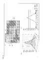
- FIG. 7 illustrates a distribution of values of electrostatic capacitance signals on a touch panel provided in the touch sensor system.
- ( b ) of FIG. 7 is a three-dimensional graph of a distribution map of the electrostatic capacitance signals.
- ( c ) of FIG. 7 is a graph illustrating a relationship among the fourth row of the distribution (see ( a ) of FIG. 7 ) of the values of the electrostatic capacitance signals, a pen input threshold, and a peripheral threshold.
- FIG. 8 illustrates another distribution of values of electrostatic capacitance signals on the touch panel.
- ( b ) of FIG. 8 is a three-dimensional graph of a distribution map of the electrostatic capacitance signals.
- ( c ) of FIG. 8 is a graph illustrating a relationship among the fourth of the distribution (see ( a ) of FIG. 8 ) of the values of the electrostatic capacitance signals, a pen input threshold, and a peripheral threshold.
- FIG. 9 illustrates still another distribution of values of electrostatic capacitance signals on the touch panel.
- ( b ) of FIG. 9 is a three-dimensional graph of a distribution map of the electrostatic capacitance signals.
- ( c ) of FIG. 9 is a graph illustrating a relationship among the fourth row of the distribution (see ( a ) of FIG. 9 ) of the values of the electrostatic capacitance signals, a pen input threshold, and a peripheral threshold.
- FIG. 10 illustrates still another distribution of values of electrostatic capacitance signals on the touch panel.
- ( b ) of FIG. 10 is a three-dimensional graph of a distribution map of the electrostatic capacitance signals.
- ( c ) of FIG. 10 is a graph illustrating a relationship among the fourth row of the distribution (see ( a ) of FIG. 10 ) of the values of the electrostatic capacitance signals, a strength threshold, and a peripheral threshold.
- FIG. 11 illustrates still another distribution of values of electrostatic capacitance signals on the touch panel.
- ( b ) of FIG. 11 is a three-dimensional graph of a distribution map of the electrostatic capacitance signals.
- ( c ) of FIG. 11 is a graph illustrating a relationship among the seventh row of the distribution (see ( a ) of FIG. 11 ) of the values of the electrostatic capacitance signals, a strength threshold, and a peripheral threshold.
- FIG. 12 is a block diagram illustrating a configuration of a conventional touch sensor system.
- FIG. 1 is a block diagram illustrating a configuration of a touch sensor system 1 in accordance with Embodiment 1.
- the touch sensor system 1 includes a touch panel 7 and an electrostatic capacitance value distribution detecting circuit 18 .
- the touch panel 7 includes drive lines HL 1 through HLn arranged parallel to each other in a horizontal direction, sense lines VL 1 through VLm arranged parallel to each other in a vertical direction, and a plurality of electrostatic capacitances formed at intersections of the drive lines HL 1 through HLn and the sense lines VL 1 through VLm.
- the electrostatic capacitance value distribution detecting circuit 18 includes a driver 9 .
- the driver 9 drives the plurality of electrostatic capacitances by a voltage application to the drive lines HL 1 through HLn in accordance with a code sequence.
- the electrostatic capacitance value distribution detecting circuit 18 includes a sense amplifier 10 .
- the sense amplifier 10 reads out, via the sense lines VL 1 through VLm, a linear sum of voltages corresponding to the respective plurality of electrostatic capacitances driven by the driver 9 , and then supplies the linear sum of voltages to an AD converter 12 .
- the AD converter 12 subjects, to AD conversion, the linear sum of the voltages which has been read out via the sense lines VL 1 through VLm, the voltages corresponding to the respective plurality of electrostatic capacitances, and then supplies, to a capacitance distribution calculating section 3 , the linear sum of the voltages which has been subjected to the AD conversion.
- the capacitance distribution calculating section 3 calculates an electrostatic capacitance distribution on the touch panel 7 in accordance with the code sequence and the linear sum of the voltages which has been supplied from the AD converter 12 , the voltages corresponding to the respective plurality of electrostatic capacitances, and then supplies the electrostatic capacitance distribution thus calculated to a hand placing removing process section 2 .
- FIG. 2 is a block diagram illustrating a configuration of the hand placing removing process section 2 provided in the touch sensor system 1 .
- the hand placing removing process section 2 includes a detecting section 5 and a replacing section 6 .
- the detecting section 5 detects, in accordance with (i) an electrostatic capacitance signal indicative of a change in electrostatic capacitance and (ii) a parameter stored in a hand placing parameter storage section 8 , a hand placing region indicative of a region in which a hand is placed so as to carry out a pen input or a finger input with respect to the touch panel 7 which includes the plurality of electrostatic capacitances provided in a matrix pattern.
- the detecting section 5 detects the hand placing region in accordance with (i) a strength threshold for determining a strength of an electrostatic capacitance signal in a detection region so as to determine whether or not a touch input is carried out by a finger and (ii) a peripheral threshold which is lower than the strength threshold and is set so as to determine strengths of electrostatic capacitance signals in a plurality of peripheral regions surrounding the detection region.
- the detecting section 6 determines that the detection region is the hand placing region.
- the detecting section 5 can detect the hand placing region in accordance with (i) a pen input threshold for determining whether or not the touch input is carried out by a pen and (ii) the peripheral threshold.
- the replacing section 6 replaces, by a non-value indicative of a state in which no touch input is carried out, a value of an electrostatic capacitance signal which value corresponds to an electrostatic capacitance provided in the hand placing region thus detected by the detecting section 5 , and then supplies the electrostatic capacitance signal to a touch recognizing section 4 (see FIG. 1 ).
- the touch recognizing section 4 supplies, to a host device 13 connected to an outside of the touch sensor system 1 , a coordinate value of the touch input by a pen or a finger.
- the host device 13 carries out a process by use of application software in accordance with the coordinate value of the touch input which coordinate value has been supplied from the touch recognizing section 4 .
- the electrostatic capacitance value distribution detecting circuit 18 includes a timing generator 11 .
- the timing generator 11 generates (i) a signal which specifies operation of the driver 9 , (ii) a signal which specifies operation of the sense amplifier 10 , and (iii) a signal which specifies operation of the AD converter 12 , and then supplies the signals (i) through (iii) to the driver 9 , the sense amplifier 10 , and the AD converter 12 , respectively.
- FIG. 3 illustrates a method in accordance with the touch sensor system 1 for detecting a hand placing region.
- FIG. 3 schematically illustrates how handwriting with a pen 14 is carried out while a hand 15 is being placed on a touch panel 7 which includes n drive lines and m sense lines.
- FIG. 4 is a flowchart illustrating operation of the touch sensor system 1 in accordance with the embodiment.
- the touch panel system 1 shown in FIG. 1 is turned on (step 1 ).
- the parameter stored in the hand placing parameter storage section 8 provided in the capacitance distribution detecting circuit 18 of the touch panel system 1 is initialized (step S 2 ).
- the touch panel 7 is driven by the driver 9 (step S 3 ).
- an electrostatic capacitance signal read out from the touch panel 7 by the sense amplifier 10 is subjected to AD conversion by the AD converter 12 (step S 4 ).
- the capacitance distribution calculating section 3 calculates a capacitance distribution on the touch panel 7 in accordance with the electrostatic capacitance signal subjected to AD conversion by the AD converter 12 (step S 5 ).
- the hand placing removing process section 2 calculates the hand placing region in accordance with the capacitance distribution on the touch panel 7 which capacitance distribution has been calculated by the capacitance distribution calculating section 3 (step S 6 ).
- the hand placing removing process section 2 sets a replacement region in accordance with the hand placing region thus calculated, and replaces a capacitance value in the replacement region by zero (step S 7 ).
- the touch recognizing section 4 finds a coordinate value of a touch input in accordance with the capacitance distribution on the touch panel 7 in which capacitance distribution the capacitance value in the replacement region has been replaced by zero (step S 8 ).
- the touch recognizing section 4 supplies the coordinate value of the touch input to the host device 13 (step S 9 ). Then, the operation returns to step S 3 .
- FIG. 5 is a flowchart illustrating operation of the hand placing removing process section 2 . This flowchart corresponds to a detailed flowchart of steps S 6 and S 7 illustrated in FIG. 4 .
- an electrostatic capacitance signal in accordance with a touch input to the hand placing region is removed by recognizing, by discrimination, a pen touch and a finger touch.
- a process for determining the pen touch is carried out at steps S 14 through S 16
- a process for determining the finger touch is carried out at steps S 23 through S 25 .
- the detecting section 5 provided in the hand placing removing process section 2 initializes, to 1, the flag Flag[j][i] stored in the hand placing parameter storage section 8 . Further, it is determined at step S 12 whether or not the capacitance value C[j][i] of the touch panel 7 is greater than the pen input threshold PEN_THRESH.
- a counter count is initialized to 0 (step S 13 ).
- step S 14 it is determined at step S 15 whether or not the capacitance value C[q][p] of the touch panel 7 is greater than the peripheral threshold FOOT_THRESH. In a case where it is determined that the capacitance value C[q][p] is greater than the peripheral threshold FOOT_THRESH (YES at step S 15 ), a value of the counter count is increased only by 1 at step S 16 .
- step S 17 when the repeat of the process with respect to the coordinates (p, q) which satisfy the following formulas: j ⁇ dm 1 ⁇ q ⁇ j+dp 1 i ⁇ sm 1 ⁇ p ⁇ i+sp 1 is finished, it is determined at step S 17 whether or not the counter count is greater than the area threshold AREA_THRESH. In a case where it is determined that the counter count is greater than the area threshold AREA_THRESH (YES at step S 17 ), the flag Flag[j][i] is set to 0 at step S 18 .
- the counter count is initialized to 0 (step S 22 ). Subsequently, the process carried out at steps S 23 through S 25 is repeated for coordinates (p, q) which satisfy the following formulas: j ⁇ dm 1 ⁇ q ⁇ j+dp 1 i ⁇ sm 1 ⁇ p ⁇ i+sp 1 In a case where it is determined at step S 23 that coordinates (p, q) satisfy the following formulas: j ⁇ dm 2 ⁇ q ⁇ j+dp 2 i ⁇ sm 2 ⁇ p ⁇ i+sp 2 (YES at step S 23 ), the process carried out at steps S 23 through S 25 is repeated with respect to subsequent coordinates (p, q).
- step S 23 it is determined at step 24 whether or not the capacitance value C[q][p] of the touch panel 7 is greater than the second peripheral threshold FOOT_THRESH2. In a case where it is determined that the capacitance value C[q][p] is greater than the second peripheral threshold FOOT_THRESH2 (YES at step S 24 ), the value of the counter count is increased only by 1 at step S 25 .
- step S 26 when the repeat of the process with respect to the coordinates (p, q) which satisfy the following formulas: j ⁇ dm 1 ⁇ q ⁇ j+dp 1 i ⁇ sm 1 ⁇ p ⁇ i+sp 1 is finished, it is determined at step S 26 whether or not the counter count is greater than the second area threshold AREA_THRESH2. In a case where it is determined that the counter count is greater than the second area threshold AREA_THRESH2 (YES at step S 26 ), the flag Flag[j][i] is set to 0 at step S 27 .
- the electrostatic capacitance value obtained in the hand placing region does not need to be replaced by zero but the setting can be carried out by any method provided that the hand placing region can be set to a non-detection region of a touch recognition. It is only necessary that the electrostatic capacitance value obtained in the hand placing region be replaced by a non-value indicative of a state in which no touch input is carried out.
- step S 10 the hand placing removing process section 2 transmits, to the touch recognizing section 4 , the replaced capacitance value C[j][i] subjected to the replacement (step S 20 ).
- the parameter PALM_MODE is a flag indicating whether a hand placing mode is ON or OFF and is stored in the hand placing parameter storage section 8 . In a case where PALM_MODE is ON, a hand placing response process shown in steps S 11 through S 27 is carried out.
- the electrostatic capacitance value obtained in the hand placing region does not need to be replaced by zero but the setting can be carried out by any method provided that the hand placing region can be set to a non-detection region of a touch recognition. It is only necessary that the electrostatic capacitance value obtained in the hand placing region be replaced by a non-value indicative of a state in which no touch input is carried out.
- FIG. 6 illustrates a relationship between the coordinates (i, j) and the parameters described in the process carried out at steps S 14 through S 16 and S 23 through S 25 .
- a detection region R 1 which determines a strength of an electrostatic capacitance signal so as to determine whether or not the touch input is carried out by a finger has coordinates (i, j) and is surrounded by a plurality of peripheral regions R 2 having a doughnut-shape. Intermediate regions R 3 are provided between the detection region R 1 and the plurality of peripheral regions R 2 .
- the coordinates of the detection region R 1 are (i, j) and coordinates of a peripheral region R 2 on an upper left are (i ⁇ sm1, j ⁇ dm1). Coordinates of a peripheral region R 2 on a lower left are (i+sp1, j ⁇ dm1), coordinates of a peripheral region R 2 on an upper right are (i ⁇ sm1, j+dp1), and coordinates of a peripheral region R 2 on a lower right are (i+sp1, j+dp1).
- Coordinates of an intermediate region R 3 on the upper left are (i ⁇ sm2, j ⁇ dm2), coordinates of an intermediate region R 3 on the lower left are (i+sp2, j ⁇ dm2). Coordinates of an intermediate region R 3 on the upper right are (i ⁇ sm2, j+dp2) and coordinates of an intermediate region R 3 on the lower right are (i+sp2, j+dp2).
- FIG. 7 is an example in which a part of a capacitance distribution map (an area around a pen touch position) is actually measured in a case where a touch panel is touched with a pen.
- This capacitance distribution map is generated by the capacitance distribution calculating section 3 shown in FIG. 1 .
- the pen touch position is detected by carrying out sequential rightward scanning with respect to the capacitance distribution map from an upper left of the capacitance distribution map.
- An arrangement of the detection region R 1 , the peripheral regions R 2 , and the intermediate regions R 3 which arrangement is shown in ( a ) of FIG. 7 corresponds to an arrangement in which the parameters shown in FIG. 6 are set as below assuming that coordinates of the detection region R 1 are (i, j).
- FIG. 7 is a three-dimensional graph of the capacitance distribution map shown in ( a ) of FIG. 7 .
- ( c ) of FIG. 7 graphs the fourth row of the capacitance distribution map of ( a ) of FIG. 7 .
- a region (a plurality of peripheral regions R 2 ) located outside a rectangular region with 5 rows and 4 columns which rectangular region is enclosed with a thick line and includes the detection region R 1 and the intermediate regions R 3 (see ( a ) of FIG. 7 ) serves as a region in which it is determined whether an electrostatic capacitance signal value is greater than the peripheral threshold FOOT_THRESH.
- This causes the counter count to be 0. Therefore, for example, in a case where the area threshold is set to AREA_THRESH 3, count>AREA_THRESH is not satisfied.
- the flag Flag[j][i] remains 1 and does not change. Therefore, it is determined that the touch input is carried out by a pen at the coordinates (i, j), so that C[j][i] is not zerofilled.
- FIG. 8 are a capacitance distribution map obtained at the moment at which a fist is brought into contact with the touch panel 7 , and graphs of the capacitance distribution map.
- a plurality of peripheral regions R 2 located outside a rectangular region with 5 rows and 4 columns which rectangular region is enclosed with a thick line serve as a region in which it is determined whether an electrostatic capacitance signal value is greater than the peripheral threshold FOOT_THRESH.
- FIG. 9 are a capacitance distribution map obtained in a state in which a fist is in contact with the touch panel, and graphs of the capacitance distribution map.
- FIG. 10 is an example in which a part of the capacitance distribution map (an area around a finger touch position) is actually measured in a case where the touch panel is touched with a finger.
- This capacitance distribution map is generated by the capacitance distribution calculating section 3 shown in FIG. 1 .
- the finger touch position is detected by carrying out sequential rightward scanning with respect to the capacitance distribution map from an upper left of the capacitance distribution map.
- ( a ) of FIG. 10 corresponds to a case where the parameters shown in FIG. 6 are set as below assuming that coordinates corresponding to the detection region R 1 are (i, j).
- FIG. 10 is a three-dimensional graph of the capacitance distribution map of ( a ) of FIG. 10 .
- ( c ) of FIG. 10 graphs electrostatic capacitance values of regions in the fourth row of the capacitance distribution map of ( a ) of FIG. 10 .
- a region located outside a rectangular region with 5 rows and 4 columns which rectangular region is enclosed with a thick line and the detection region R 1 and the intermediate regions R 3 serves as a region in which it is determined whether or not an electrostatic capacitance signal value is greater than the second peripheral threshold FOOT_THRESH2.
- FOOT_THRESH2 the second peripheral threshold
- the flag Flag[j][i] remains 1 and does not change. Therefore, it is determined that the detection region R 1 at the coordinates (i, j) is a region in which the touch input is carried out by a finger but is not a hand placing region, so that C[j][i] is not zerofilled.
- FIG. 11 are a capacitance distribution map obtained in a state in which a fist is in contact with the touch panel, and graphs of the capacitance distribution map.
- parameters s are set to values identical to those set as the parameters in the case of the finger input shown in FIG. 10
- a region located outside a rectangle with 5 rows and 4 columns which rectangle includes the detection region R 1 and the intermediate regions R 3 and is enclosed with a thick line serves as a region in which it is determined whether or not an electrostatic capacitance signal value is greater than the second peripheral threshold FOOT_THRESH2.
- the flag Flag[j][i] is changed to 0. Therefore, it is determined that the detection region R 1 at the coordinates (i, j) is not a region in which the touch input is carried out by a finger but is a hand placing region, so that C[j][i] is zerofilled.
- the present embodiment gives an example of an electrostatic capacitance touch sensor system.
- the present invention is not limited to this.
- the present invention is also applicable to a touch sensor system other than the electrostatic capacitance touch sensor system.
- the present invention is also applicable to an electromagnetic induction touch sensor system.
- the touch sensor system of the present invention is preferably configured such that in a case where (i) the strength of the electrostatic capacitance signal in the detection region exceeds the strength threshold and (ii) the number of peripheral regions in each of which a strength of an electrostatic capacitance signal exceeds the peripheral threshold exceeds a predetermined area threshold, the detecting means determines that the detection region is the hand placing region.
- the touch sensor system of the present invention is preferably configured such that an intermediate region is provided between the detection region and the plurality of peripheral regions.
- the touch sensor system of the present invention is preferably configured such that the detecting means detects the hand placing region in accordance with a pen input threshold for determining whether or not the touch input is carried out by a pen.
- the present invention is applicable to a touch sensor system for detecting a pen input and a finger input to a touch panel including a plurality of electrostatic capacitances provided in a matrix pattern.
Landscapes
- Engineering & Computer Science (AREA)
- General Engineering & Computer Science (AREA)
- Theoretical Computer Science (AREA)
- Human Computer Interaction (AREA)
- Physics & Mathematics (AREA)
- General Physics & Mathematics (AREA)
- Position Input By Displaying (AREA)
Priority Applications (1)
| Application Number | Priority Date | Filing Date | Title |
|---|---|---|---|
| US13/903,558 US8937609B2 (en) | 2012-05-30 | 2013-05-28 | Touch sensor system |
Applications Claiming Priority (4)
| Application Number | Priority Date | Filing Date | Title |
|---|---|---|---|
| JP2012-122743 | 2012-05-30 | ||
| JP2012122743A JP5886139B2 (ja) | 2012-05-30 | 2012-05-30 | タッチセンサシステム |
| US201261653738P | 2012-05-31 | 2012-05-31 | |
| US13/903,558 US8937609B2 (en) | 2012-05-30 | 2013-05-28 | Touch sensor system |
Publications (2)
| Publication Number | Publication Date |
|---|---|
| US20130321334A1 US20130321334A1 (en) | 2013-12-05 |
| US8937609B2 true US8937609B2 (en) | 2015-01-20 |
Family
ID=49669616
Family Applications (1)
| Application Number | Title | Priority Date | Filing Date |
|---|---|---|---|
| US13/903,558 Expired - Fee Related US8937609B2 (en) | 2012-05-30 | 2013-05-28 | Touch sensor system |
Country Status (4)
| Country | Link |
|---|---|
| US (1) | US8937609B2 (ja) |
| JP (1) | JP5886139B2 (ja) |
| TW (1) | TWI553533B (ja) |
| WO (1) | WO2013179474A1 (ja) |
Cited By (6)
| Publication number | Priority date | Publication date | Assignee | Title |
|---|---|---|---|---|
| US20150153856A1 (en) * | 2013-12-02 | 2015-06-04 | Samsung Electro-Mechanics Co., Ltd. | Touchscreen device and method of sensing touch |
| US20160132149A1 (en) * | 2013-06-20 | 2016-05-12 | Sharp Kabushiki Kaisha | Touch panel controller, integrated circuit, touch panel device, and electronic device |
| US9501166B2 (en) * | 2015-03-30 | 2016-11-22 | Sony Corporation | Display method and program of a terminal device |
| US9904379B2 (en) | 2016-02-29 | 2018-02-27 | Apple Inc. | Disabling stylus to prevent worn tip performance degradation and screen damage |
| US20220294935A1 (en) * | 2019-07-01 | 2022-09-15 | Sony Interactive Entertainment Inc. | Information processing device, information processing method, and program |
| US11559183B2 (en) | 2016-10-31 | 2023-01-24 | Daio Paper Corporation | Wet sheet for cleaning |
Families Citing this family (10)
| Publication number | Priority date | Publication date | Assignee | Title |
|---|---|---|---|---|
| US10209816B2 (en) | 2013-07-04 | 2019-02-19 | Samsung Electronics Co., Ltd | Coordinate measuring apparatus for measuring input position of a touch and a coordinate indicating apparatus and driving method thereof |
| KR102209910B1 (ko) | 2013-07-04 | 2021-02-01 | 삼성전자주식회사 | 위치 표시 장치의 입력 위치를 측정하는 위치 측정 장치 및 그 제어 방법 |
| WO2016002300A1 (ja) * | 2014-06-30 | 2016-01-07 | シャープ株式会社 | タッチパネルシステム及び電子機器 |
| TWI526952B (zh) * | 2014-08-21 | 2016-03-21 | 義隆電子股份有限公司 | 電容式觸控裝置及其物件辨識方法 |
| US10126854B2 (en) * | 2015-03-06 | 2018-11-13 | Sony Mobile Communications Inc. | Providing touch position information |
| JP6532128B2 (ja) * | 2015-09-14 | 2019-06-19 | 株式会社東海理化電機製作所 | 操作検出装置 |
| JP6473680B2 (ja) * | 2015-09-15 | 2019-02-20 | シャープ株式会社 | 入力表示装置および入力表示方法 |
| JP6768562B2 (ja) * | 2017-03-06 | 2020-10-14 | シャープ株式会社 | タッチパネルコントローラ及びタッチパネルシステム |
| CN110597414B (zh) * | 2019-09-12 | 2023-02-03 | 青岛海信商用显示股份有限公司 | 触摸屏的触控检测方法及相关设备 |
| CN115701571B (zh) * | 2021-08-02 | 2026-04-03 | 维沃移动通信有限公司 | 触控位置确定方法、装置及电子设备 |
Citations (9)
| Publication number | Priority date | Publication date | Assignee | Title |
|---|---|---|---|---|
| US7358741B2 (en) * | 2004-05-25 | 2008-04-15 | Alps Electric Co., Ltd | Electrostatic detection apparatus and method, and coordinate detection program |
| US7812828B2 (en) | 1998-01-26 | 2010-10-12 | Apple Inc. | Ellipse fitting for multi-touch surfaces |
| US7812827B2 (en) | 2007-01-03 | 2010-10-12 | Apple Inc. | Simultaneous sensing arrangement |
| JP2010244132A (ja) | 2009-04-01 | 2010-10-28 | Mitsubishi Electric Corp | タッチパネル付きユーザインタフェース装置、ユーザインタフェース制御方法およびユーザインタフェース制御プログラム |
| US20110037727A1 (en) * | 2008-03-12 | 2011-02-17 | Atlab Inc. | Touch sensor device and pointing coordinate determination method thereof |
| US20110084934A1 (en) | 2009-10-13 | 2011-04-14 | Sony Corporation | Information input device, information input method, information input/output device, computer readable non-transitory recording medium and electronic unit |
| US8085243B2 (en) * | 2006-02-03 | 2011-12-27 | Panasonic Corporation | Input device and its method |
| US8179408B2 (en) * | 2008-08-13 | 2012-05-15 | Au Optronics Corp. | Projective capacitive touch apparatus, and method for identifying distinctive positions |
| US8259086B2 (en) * | 2007-11-12 | 2012-09-04 | Mitsubishi Electric Corporation | Touch panel and display device comprising the same |
Family Cites Families (9)
| Publication number | Priority date | Publication date | Assignee | Title |
|---|---|---|---|---|
| JP2006039686A (ja) * | 2004-07-22 | 2006-02-09 | Pioneer Electronic Corp | タッチパネル装置、タッチ領域検出方法およびタッチ領域検出プログラム |
| TWM335727U (en) * | 2007-05-15 | 2008-07-01 | Htc Corp | Electronic device with obstacle-free touch operation |
| JP4626658B2 (ja) * | 2008-02-14 | 2011-02-09 | ソニー株式会社 | 表示装置、撮像装置および位置検出装置 |
| WO2010035878A1 (ja) * | 2008-09-29 | 2010-04-01 | 京セラ株式会社 | 電子機器及び電子機器における表示方法 |
| CN102150115B (zh) * | 2009-02-06 | 2014-06-11 | 松下电器产业株式会社 | 图像显示设备 |
| TW201104531A (en) * | 2009-07-17 | 2011-02-01 | Egalax Empia Technology Inc | Method and device for palm rejection |
| JP2011134069A (ja) * | 2009-12-24 | 2011-07-07 | Panasonic Corp | タッチパネル装置 |
| TW201122984A (en) * | 2009-12-29 | 2011-07-01 | Higgstec Inc | Touch system, dual input touch system and the detecting method thereof |
| CN102339187B (zh) * | 2011-10-26 | 2013-09-25 | 苏州瀚瑞微电子有限公司 | 电容式触控屏手掌判别方法 |
-
2012
- 2012-05-30 JP JP2012122743A patent/JP5886139B2/ja not_active Expired - Fee Related
- 2012-05-31 WO PCT/JP2012/064240 patent/WO2013179474A1/ja not_active Ceased
- 2012-06-01 TW TW101119846A patent/TWI553533B/zh not_active IP Right Cessation
-
2013
- 2013-05-28 US US13/903,558 patent/US8937609B2/en not_active Expired - Fee Related
Patent Citations (10)
| Publication number | Priority date | Publication date | Assignee | Title |
|---|---|---|---|---|
| US7812828B2 (en) | 1998-01-26 | 2010-10-12 | Apple Inc. | Ellipse fitting for multi-touch surfaces |
| US7358741B2 (en) * | 2004-05-25 | 2008-04-15 | Alps Electric Co., Ltd | Electrostatic detection apparatus and method, and coordinate detection program |
| US8085243B2 (en) * | 2006-02-03 | 2011-12-27 | Panasonic Corporation | Input device and its method |
| US7812827B2 (en) | 2007-01-03 | 2010-10-12 | Apple Inc. | Simultaneous sensing arrangement |
| US8259086B2 (en) * | 2007-11-12 | 2012-09-04 | Mitsubishi Electric Corporation | Touch panel and display device comprising the same |
| US20110037727A1 (en) * | 2008-03-12 | 2011-02-17 | Atlab Inc. | Touch sensor device and pointing coordinate determination method thereof |
| US8179408B2 (en) * | 2008-08-13 | 2012-05-15 | Au Optronics Corp. | Projective capacitive touch apparatus, and method for identifying distinctive positions |
| JP2010244132A (ja) | 2009-04-01 | 2010-10-28 | Mitsubishi Electric Corp | タッチパネル付きユーザインタフェース装置、ユーザインタフェース制御方法およびユーザインタフェース制御プログラム |
| US20110084934A1 (en) | 2009-10-13 | 2011-04-14 | Sony Corporation | Information input device, information input method, information input/output device, computer readable non-transitory recording medium and electronic unit |
| JP2011086003A (ja) | 2009-10-13 | 2011-04-28 | Sony Corp | 情報入力装置、情報入力方法、情報入出力装置、情報入力プログラムおよび電子機器 |
Cited By (8)
| Publication number | Priority date | Publication date | Assignee | Title |
|---|---|---|---|---|
| US20160132149A1 (en) * | 2013-06-20 | 2016-05-12 | Sharp Kabushiki Kaisha | Touch panel controller, integrated circuit, touch panel device, and electronic device |
| US9658728B2 (en) * | 2013-06-20 | 2017-05-23 | Sharp Kabushiki Kaisha | Touch panel controller, integrated circuit, touch panel device, and electronic device |
| US20150153856A1 (en) * | 2013-12-02 | 2015-06-04 | Samsung Electro-Mechanics Co., Ltd. | Touchscreen device and method of sensing touch |
| US9501166B2 (en) * | 2015-03-30 | 2016-11-22 | Sony Corporation | Display method and program of a terminal device |
| US9904379B2 (en) | 2016-02-29 | 2018-02-27 | Apple Inc. | Disabling stylus to prevent worn tip performance degradation and screen damage |
| US11559183B2 (en) | 2016-10-31 | 2023-01-24 | Daio Paper Corporation | Wet sheet for cleaning |
| US20220294935A1 (en) * | 2019-07-01 | 2022-09-15 | Sony Interactive Entertainment Inc. | Information processing device, information processing method, and program |
| US11943519B2 (en) * | 2019-07-01 | 2024-03-26 | Sony Interactive Entertainment Inc. | Information processing device, information processing method, and program |
Also Published As
| Publication number | Publication date |
|---|---|
| US20130321334A1 (en) | 2013-12-05 |
| TWI553533B (zh) | 2016-10-11 |
| JP5886139B2 (ja) | 2016-03-16 |
| TW201349067A (zh) | 2013-12-01 |
| JP2013250596A (ja) | 2013-12-12 |
| WO2013179474A1 (ja) | 2013-12-05 |
Similar Documents
| Publication | Publication Date | Title |
|---|---|---|
| US8937609B2 (en) | Touch sensor system | |
| US8970538B2 (en) | Touch sensor system | |
| CN103019483B (zh) | 触控对象识别方法 | |
| TWI502458B (zh) | 觸控面板之液體識別方法 | |
| US9710108B2 (en) | Touch sensor control device having a calibration unit for calibrating detection sensitivity of a touch except for a mask region | |
| US11422660B2 (en) | Input device, input method and program | |
| JP2012160172A5 (ja) | ||
| JP7825083B2 (ja) | 集積回路 | |
| CN108021279A (zh) | 触控处理装置、方法与电子系统 | |
| US20160147373A1 (en) | Input device, and control method and program therefor | |
| US9779674B2 (en) | Touch panel system | |
| US20180329532A1 (en) | Operation detection device | |
| EP2672363A2 (en) | Display device and method using a plurality of display panels | |
| KR102008780B1 (ko) | 표시장치 및 그 구동방법 | |
| KR102092664B1 (ko) | 차동 터치 센싱 시스템의 좌표 선택 회로 및 방법 | |
| CN102253778B (zh) | 一种电容传感器的定位方法 | |
| JP2011043922A (ja) | 移動体認識装置、移動体認識方法及びプログラム | |
| CN102436333B (zh) | 兼容电容定位和电磁定位的输入装置及其输入方法 | |
| JPWO2016204069A1 (ja) | 入力装置、物体検出装置及びその方法 | |
| JP6061426B2 (ja) | 入力装置及びその情報入力方法 | |
| US20250216976A1 (en) | Display device | |
| KR102092665B1 (ko) | 차동 터치 센싱 시스템의 좌표 계산 장치 및 방법 | |
| KR20180029405A (ko) | 테이블 탑 디스플레이 장치 및 그 터치 인식 방법 |
Legal Events
| Date | Code | Title | Description |
|---|---|---|---|
| AS | Assignment |
Owner name: SHARP KABUSHIKI KAISHA, JAPAN Free format text: ASSIGNMENT OF ASSIGNORS INTEREST;ASSIGNORS:YOSHIDA, SHINICHI;MORISHITA, TAKAHIRO;REEL/FRAME:030503/0078 Effective date: 20130426 |
|
| STCF | Information on status: patent grant |
Free format text: PATENTED CASE |
|
| FEPP | Fee payment procedure |
Free format text: PAYOR NUMBER ASSIGNED (ORIGINAL EVENT CODE: ASPN); ENTITY STATUS OF PATENT OWNER: LARGE ENTITY |
|
| MAFP | Maintenance fee payment |
Free format text: PAYMENT OF MAINTENANCE FEE, 4TH YEAR, LARGE ENTITY (ORIGINAL EVENT CODE: M1551) Year of fee payment: 4 |
|
| FEPP | Fee payment procedure |
Free format text: MAINTENANCE FEE REMINDER MAILED (ORIGINAL EVENT CODE: REM.); ENTITY STATUS OF PATENT OWNER: LARGE ENTITY |
|
| LAPS | Lapse for failure to pay maintenance fees |
Free format text: PATENT EXPIRED FOR FAILURE TO PAY MAINTENANCE FEES (ORIGINAL EVENT CODE: EXP.); ENTITY STATUS OF PATENT OWNER: LARGE ENTITY |
|
| STCH | Information on status: patent discontinuation |
Free format text: PATENT EXPIRED DUE TO NONPAYMENT OF MAINTENANCE FEES UNDER 37 CFR 1.362 |
|
| FP | Lapsed due to failure to pay maintenance fee |
Effective date: 20230120 |