WO2013175684A1 - 車両周囲画像表示制御装置、車両周囲画像表示制御方法、当該方法を含む命令からなる持続的有形コンピュータ読み取り媒体、車両の周囲の画像をトップビュー変換して表示させる画像処理方法 - Google Patents
車両周囲画像表示制御装置、車両周囲画像表示制御方法、当該方法を含む命令からなる持続的有形コンピュータ読み取り媒体、車両の周囲の画像をトップビュー変換して表示させる画像処理方法 Download PDFInfo
- Publication number
- WO2013175684A1 WO2013175684A1 PCT/JP2013/001489 JP2013001489W WO2013175684A1 WO 2013175684 A1 WO2013175684 A1 WO 2013175684A1 JP 2013001489 W JP2013001489 W JP 2013001489W WO 2013175684 A1 WO2013175684 A1 WO 2013175684A1
- Authority
- WO
- WIPO (PCT)
- Prior art keywords
- bird
- image
- history
- vehicle
- area
- Prior art date
- Legal status (The legal status is an assumption and is not a legal conclusion. Google has not performed a legal analysis and makes no representation as to the accuracy of the status listed.)
- Ceased
Links
Images


Classifications
-
- G—PHYSICS
- G06—COMPUTING OR CALCULATING; COUNTING
- G06T—IMAGE DATA PROCESSING OR GENERATION, IN GENERAL
- G06T5/00—Image enhancement or restoration
- G06T5/90—Dynamic range modification of images or parts thereof
- G06T5/94—Dynamic range modification of images or parts thereof based on local image properties, e.g. for local contrast enhancement
-
- G—PHYSICS
- G06—COMPUTING OR CALCULATING; COUNTING
- G06T—IMAGE DATA PROCESSING OR GENERATION, IN GENERAL
- G06T3/00—Geometric image transformations in the plane of the image
- G06T3/04—Context-preserving transformations, e.g. by using an importance map
- G06T3/047—Fisheye or wide-angle transformations
-
- G—PHYSICS
- G06—COMPUTING OR CALCULATING; COUNTING
- G06T—IMAGE DATA PROCESSING OR GENERATION, IN GENERAL
- G06T5/00—Image enhancement or restoration
- G06T5/50—Image enhancement or restoration using two or more images, e.g. averaging or subtraction
-
- G—PHYSICS
- G08—SIGNALLING
- G08G—TRAFFIC CONTROL SYSTEMS
- G08G1/00—Traffic control systems for road vehicles
- G08G1/16—Anti-collision systems
- G08G1/168—Driving aids for parking, e.g. acoustic or visual feedback on parking space
-
- G—PHYSICS
- G06—COMPUTING OR CALCULATING; COUNTING
- G06T—IMAGE DATA PROCESSING OR GENERATION, IN GENERAL
- G06T2207/00—Indexing scheme for image analysis or image enhancement
- G06T2207/10—Image acquisition modality
- G06T2207/10016—Video; Image sequence
-
- G—PHYSICS
- G06—COMPUTING OR CALCULATING; COUNTING
- G06T—IMAGE DATA PROCESSING OR GENERATION, IN GENERAL
- G06T2207/00—Indexing scheme for image analysis or image enhancement
- G06T2207/10—Image acquisition modality
- G06T2207/10024—Color image
-
- G—PHYSICS
- G06—COMPUTING OR CALCULATING; COUNTING
- G06T—IMAGE DATA PROCESSING OR GENERATION, IN GENERAL
- G06T2207/00—Indexing scheme for image analysis or image enhancement
- G06T2207/20—Special algorithmic details
- G06T2207/20212—Image combination
-
- G—PHYSICS
- G06—COMPUTING OR CALCULATING; COUNTING
- G06T—IMAGE DATA PROCESSING OR GENERATION, IN GENERAL
- G06T2207/00—Indexing scheme for image analysis or image enhancement
- G06T2207/30—Subject of image; Context of image processing
- G06T2207/30248—Vehicle exterior or interior
- G06T2207/30252—Vehicle exterior; Vicinity of vehicle
- G06T2207/30264—Parking
-
- G—PHYSICS
- G06—COMPUTING OR CALCULATING; COUNTING
- G06T—IMAGE DATA PROCESSING OR GENERATION, IN GENERAL
- G06T2215/00—Indexing scheme for image rendering
- G06T2215/12—Shadow map, environment map
Definitions
- the present disclosure relates to a vehicle surrounding image display control device, a vehicle surrounding image display control method, a continuous tangible computer-readable medium including instructions including the method, and an image processing method for displaying an image of the surroundings of a vehicle after top view conversion. It is.
- a technique in which a camera attached to a vehicle repeatedly captures the surroundings of the vehicle, converts the captured image into a bird's-eye view image looking down from above the vehicle, and displays the bird's-eye image after the bird's-eye conversion on an image display device. It has been.
- a technique that expands an image display range around a vehicle by displaying a synthesized bird's-eye image obtained by synthesizing the bird's-eye image of the latest photographed image and the bird's-eye image of the past photographed image on the image display device.
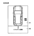
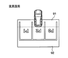
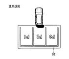
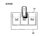
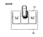
- a history area 91 for storing surrounding bird's-eye images excluding the rear of the vehicle and a bird's-eye image behind the vehicle are stored.
- a real-time area 92 is provided on the memory.
- the bird's-eye view image of the latest photographed image is overwritten in the real-time area 92 on the memory
- the combined bird's-eye view image of the history area 91 and the real-time area 92 is displayed on the image display device, and vehicle information (steering angle, vehicle speed, etc.)
- vehicle information steering angle, vehicle speed, etc.
- the movement of the vehicle is calculated, and the image is moved in the history area 91 and the real-time area 92 so as to make a movement opposite to the calculated movement of the vehicle.
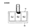
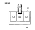
- the image displayed on the image display device when the vehicle moves backward the vehicle moves backward in the order of FIGS. 6A to 6F, and the image in the real-time area 92 becomes the history area. It moves to 91 in order. Accordingly, the range of the bird's-eye view image included in the history area 91 is sequentially expanded, and the display range around the vehicle is expanded.
- JP 2002-373327 A (corresponding to US Publication No. 20030165255) JP 2010-237976 A
- the present disclosure provides a vehicle surrounding image display control device, a vehicle surrounding image display control method, a continuous tangible computer-readable medium comprising instructions including the method, and an image processing method for displaying an image of the surroundings of the vehicle by top-view conversion.
- the purpose is to do.
- a vehicle surrounding image display control device a vehicle surrounding image display control method, a continuous tangible computer-readable medium comprising instructions including the method, and an image processing method for displaying an image around the vehicle by top-view conversion, the latest captured image
- the shadow of the host vehicle may expand in the synthesized bird's-eye image as the vehicle moves Reduce sexuality.
- the vehicle surrounding image display control device sequentially obtains a captured image around the vehicle from an in-vehicle camera mounted on the vehicle, and sequentially performs bird's-eye conversion on the captured image, A bird's-eye conversion device for creating a bird's-eye view image, and dividing the bird's-eye view image in the front-rear direction of the vehicle, thereby allowing the A bird's-eye view image in a predetermined A range farther from the vehicle and a predetermined one closer to the vehicle
- a divided storage device that creates a B bird's-eye view image of the B range, stores the A bird's-eye view image in the real A area of the memory, and stores the B bird's-eye view image in the real B area of the memory, and part or all of the real B area
- a shadow determination device that determines whether or not the stored B bird's-eye image has a shadow
- a motion calculation device that calculates the amount of movement of the vehicle based on vehicle behavior information input from the vehicle
- a C bird's-eye view image stored in the real B region is used to form a C bird's-eye image in the history C region, and the same as the real B region.
- the history B bird's-eye image in the history B region of the memory for storing the bird's-eye image of the range reflects the current surrounding arrangement of the vehicle.
- Memory history area C The history C using the history B bird's-eye image stored in the history B area based on the amount of movement of the vehicle so that the C bird's-eye image reflects the current surrounding arrangement of the vehicle.
- a C bird's-eye view image is formed in the region, and the history B bird's-eye image in the history B region reflects the current surrounding arrangement of the vehicle based on the amount of movement of the vehicle.
- a display control device that displays an image and a B bird's-eye view image in the real B region or a history B bird's-eye image in the history B region on an image display device.
- the first history image construction device based on the movement amount of the vehicle, the A range that is the display range of the A bird's-eye view image, The real A area, the real B area, and the history C area are moved so that the bird's-eye view image moves in a combined range obtained by connecting the B range that is the display range of the B bird's-eye view image and the C range that is the display range of the C bird's-eye view image.
- the history B is updated so that the bird's-eye image moves in a combined range obtained by connecting the B range, which is the display range of the history B bird's-eye image, and the A range, which is the display range of the A bird's-eye image.
- the area and the real A area may be sequentially updated.
- the first history image composing device based on the amount of movement of the vehicle, the A range and history that are the display range of the A bird's-eye image
- the real A area, the history B area, and the history C area are moved so that the bird's-eye view image moves in a combined range obtained by connecting the B range that is the display range of the B bird's-eye view image and the C range that is the display range of the C bird's-eye view image. You may update sequentially.
- the vehicle surrounding image display method repeatedly obtains captured images around the vehicle from an in-vehicle camera mounted on the vehicle, and sequentially performs bird's-eye conversion on the captured images to create a bird's-eye image. Then, by dividing the bird's-eye view image in the front-rear direction of the vehicle, the A bird's-eye image in a predetermined A range farther from the vehicle and the B bird's-eye image in a predetermined B range closer to the vehicle are created.
- the A bird's-eye view image is stored in the real A area of the memory
- the B bird's-eye view image is stored in the real B area of the memory
- the amount of movement of the vehicle is calculated based on the vehicle behavior information input from the vehicle, and when there is no shadow in the B bird's-eye view image, the bird's-eye view image in the C range outside the shooting range of the in-vehicle camera Memory for saving
- the bird's-eye view image stored in the real B region is used so that the C bird's-eye view image of the history C region reflects the current surrounding arrangement of the vehicle.
- the history B bird's-eye view image in the history B area of the memory for storing the bird's-eye view image in the same range as the real B area is configured in the history C area. Based on the amount of movement of the vehicle, a history B bird's-eye image is configured in the history B region using the A bird's-eye image stored in the real A region, and a shadow is reflected on the B bird's-eye image. In some cases, the history B stored in the history B area based on the amount of movement of the vehicle so that the C bird's-eye view image in the history C area of the memory reflects the current surrounding arrangement of the vehicle.
- the history C A C bird's-eye view image is formed in the area
- the history B bird's-eye view image in the history B area reflects the current surrounding arrangement of the vehicle based on the amount of movement of the vehicle.
- a history B bird's-eye image is configured in the history B area using the stored A bird's-eye image, and the A bird's-eye image in the real A area, the C bird's-eye image in the history C area, and the real B area
- the image display device displays a B bird's-eye view image or a history B bird's-eye image in the history B region.
- the persistent tangible computer-readable medium repeatedly acquires captured images around the vehicle from an in-vehicle camera mounted on the vehicle, sequentially performs bird's-eye conversion on the captured images, By creating and dividing the bird's-eye view image in the front-rear direction of the vehicle, an A bird's-eye image of a predetermined A range farther from the vehicle and a B bird's-eye image of a predetermined B range closer to the vehicle.
- the A bird's-eye view image is created and saved in the real A area of the memory
- the B bird's-eye view image is saved in the real B area of the memory
- there is a shadow in the bird's-eye image saved in a part or all of the real B area By creating and dividing the bird's-eye view image in the front-rear direction of the vehicle, an A bird's-eye image of a predetermined A range farther from the vehicle and a B bird's-eye image of a predetermined B range closer to the vehicle.
- the amount of movement of the vehicle is calculated based on the vehicle behavior information input from the vehicle, and when there is no shadow in the B bird's-eye view image, the bird's-eye view of the C range outside the shooting range of the in-vehicle camera Save the image
- the B bird's-eye view image stored in the real B region based on the amount of movement of the vehicle so that the C bird's-eye view image of the history C region of the memory reflects the current surrounding arrangement of the vehicle.
- the history B bird's-eye image in the history B area of the memory for storing the bird's-eye image in the same range as the real B area is used to construct a C bird's-eye image in the history C area.
- a history B bird's-eye image is configured in the history B region using the A bird's-eye image stored in the real A region based on the amount of movement of the vehicle. If there is a shadow, the C bird's-eye view image in the history C area of the memory is stored in the history B area based on the amount of movement of the vehicle so as to reflect the current surrounding arrangement of the vehicle.
- Use history B bird's-eye view image The history C region is configured to form a C bird's-eye view image, and the history B bird's-eye view image in the history B region reflects the current surrounding arrangement of the vehicle based on the amount of movement of the vehicle.
- a history B bird's-eye image is configured in the history B area using the A bird's-eye image stored in the real A area, an A bird's-eye image in the real A area, a C bird's-eye image in the history C area, and , A command for displaying a B bird's-eye image in the real B region or a history B bird's-eye image in the history B region on an image display device, the command controlling display of a vehicle surrounding image Including computer-implemented methods, comprising such instructions implemented by a computer.
- the B bird's-eye image of the real B area is used as the original image for the history synthesis (referring to constructing the C bird's-eye image in the history C area) or the history B bird's-eye image of the history B area. Whether to use or not can be selected according to the presence or absence of a shadow.
- history synthesis is performed using the history B bird's-eye image of the history B area configured based on the A bird's-eye image of the real A area (an image that is highly likely not to have a shadow). It is possible to reduce the possibility that the shadow of the own vehicle will expand in the C region. Further, when there is no shadow, history synthesis is performed using the B bird's-eye view image of the real B area, so the shooting time of the C bird's-eye image in the history C area becomes relatively new.
- WHEREIN The image of the circumference
- the image processing method divides the image after the top view conversion into two, and determines whether or not the shadow of the vehicle is included in a short-distance image closer to the vehicle among the divided images, When the shadow of the vehicle is included in the short-distance image, the current short-distance image is replaced with a history image of a long-distance image far from the vehicle photographed a predetermined time ago.
- the vehicle surrounding image display which acquires the image of the circumference
- the control device includes an acquisition device that repeatedly acquires captured images around the vehicle, a top-view conversion device that sequentially converts the captured images into a top-view and creates a series of top-view images, and the generated series of tops Of the view image group, when storing the latest top view image in the memory, by dividing the top view image in the front-rear direction of the vehicle, the far-distance top view image further away from the vehicle, A split storage device that stores in the real A area and stores the near-field top view image closer to the vehicle in the real B area, and is stored in the real B area.
- a shadow determination device that determines whether or not a shadow of the vehicle is reflected in the latest short-range top view image, and a motion that calculates the amount of motion of the vehicle based on vehicle behavior information input from the vehicle Calculating means), a history C area that is outside the photographing range of the in-vehicle camera and that corresponds to the surrounding arrangement of the vehicle, and a short-range top view image in the same range as the real B area is saved.
- the history B area to be set in the memory, and when the shadow determination means determines that there is no shadow, the short distance stored in the real B area based on the amount of movement of the vehicle
- a first history image constructing apparatus for overwriting the history C area with a top view image and overwriting the history B area with the long-range top view image stored in the real A area;
- the shadow determination unit determines that there is a shadow, based on the amount of movement of the vehicle
- the history C area is overwritten with the short-range top view image stored in the history B area, and
- a second history image constructing apparatus for overwriting the history B area with the far-distance top view image stored in the real A area; the far-range top view image in the real A area; and the history C area.
- Display control means for causing the image display device to display the history image and the short-range top view image in the real B area or the history B area.
- the short-range top view image of the real B area is used as the original image of the history synthesis (referring to constructing a history image in the history C area) or the short-range top view image of the history B area is used. Can be selected according to the presence or absence of shadows.
- history synthesis is performed using the short-range top view image of the history B area configured based on the long-range top view image of the real A area (an image with a high possibility of no shadow). Since it performs, the possibility that the shadow of the own vehicle will expand in the history C region can be reduced.
- the shooting time of the history image in the history C area becomes relatively new.
- FIG. 1 is a diagram illustrating a configuration of a vehicle surrounding image display system according to an embodiment.
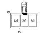
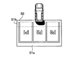
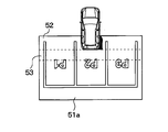
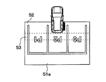
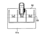
- FIG. 2 is a diagram showing a real A area, a real B area, a history C area, and a history B area in the memory.
- FIG. 3 is a flowchart of processing executed by the control device.
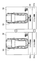
- FIG. 4A is a diagram showing a composite bird's-eye view image that changes as the vehicle moves backward when there is a shadow
- FIG. 4B is a diagram showing a composite bird's-eye view image that changes as the vehicle moves backward when there is a shadow
- FIG. 4A is a diagram showing a composite bird's-eye view image that changes as the vehicle moves backward when there is a shadow
- FIG. 4B is a diagram showing a composite bird's-eye view image that changes as the vehicle moves backward when there is a shadow
- FIG. 4A is a diagram showing a composite bird's-eye view image that changes as the vehicle moves backward when there is
- FIG. 4C is a diagram showing a synthetic bird's-eye view image that changes as the vehicle moves backward when there is a shadow
- FIG. 4D is a diagram showing a synthetic bird's-eye view image that changes as the vehicle moves backward when there is a shadow
- FIG. 4E is a diagram showing a composite bird's-eye view image that changes as the vehicle moves backward when there is a shadow
- FIG. 4F is a diagram showing a synthetic bird's-eye view image that changes as the vehicle moves backward when there is a shadow
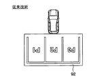
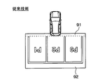
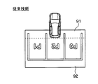
- FIG. 5 is a diagram showing a history area and a real-time area in a memory as a conventional technique.
- FIG. 5 is a diagram showing a history area and a real-time area in a memory as a conventional technique.
- FIG. 6A is a diagram showing a synthetic bird's-eye view image that changes as the vehicle moves backward as a conventional technique.
- FIG. 6B is a diagram showing a synthetic bird's-eye view image that changes as the vehicle moves backward as a conventional technique.
- FIG. 6C is a diagram showing a synthetic bird's-eye view image that changes as the vehicle moves backward as a conventional technique.
- FIG. 6D is a diagram showing a synthetic bird's-eye view image that changes as the vehicle moves backward as a conventional technique.
- FIG. 6E is a diagram showing a synthetic bird's-eye view image that changes as the vehicle moves backward as a conventional technique.
- FIG. 6A is a diagram showing a synthetic bird's-eye view image that changes as the vehicle moves backward as a conventional technique.
- FIG. 6B is a diagram showing a synthetic bird's-eye view image that changes as the vehicle moves backward as a conventional technique.
- FIG. 6C is a diagram showing
- FIG. 6F is a diagram showing a synthetic bird's-eye view image that changes as the vehicle moves backward as a conventional technique.
- FIG. 7A is a diagram showing a synthesized bird's-eye image that changes as the vehicle moves backward when there is a shadow
- FIG. 7B is a diagram showing a synthesized bird's-eye image that changes as the vehicle moves backward when there is a shadow
- FIG. 7C is a diagram showing a synthesized bird's-eye image that changes as the vehicle moves backward when there is a shadow
- FIG. 7D is a diagram showing a synthetic bird's-eye view image that changes as the vehicle moves backward when there is a shadow
- FIG. 7A is a diagram showing a synthesized bird's-eye image that changes as the vehicle moves backward when there is a shadow
- FIG. 7B is a diagram showing a synthesized bird's-eye image that changes as the vehicle moves backward when there is a shadow
- FIG. 7C
- FIG. 7E is a diagram showing a synthetic bird's-eye view image that changes as the vehicle moves backward when there is a shadow
- FIG. 7F is a diagram illustrating a synthesized bird's-eye image that changes as the vehicle moves backward when there is a shadow as a related art.
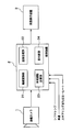
- FIG. 1 shows a configuration of a vehicle surrounding image display system according to the present embodiment.
- This vehicle surrounding image display system is mounted on a vehicle and includes an in-vehicle camera 1, a control device 2 (corresponding to an example of a vehicle surrounding image display control device), and an image display device 3.
- the in-vehicle camera 1 is fixedly mounted near the rear end of the vehicle, and repeatedly captures the surroundings of the vehicle, specifically, a predetermined range behind the vehicle (for example, in a 1/30 second cycle).
- the obtained captured image data is sequentially output to the control device 2.
- the control device 2 is configured such that the above-described captured image is repeatedly input from the in-vehicle camera 1 and shift range information, vehicle speed information, and steering angle (or yaw rate) information are repeatedly input from the host vehicle. .
- the control device 2 functions as a bird's-eye conversion unit 21, an image composition unit 22, a vehicle motion calculation unit 23, and a shadow determination unit 24 by executing a predetermined process.
- the bird's-eye conversion unit 21 performs a known bird's-eye conversion on the captured image input from the in-vehicle camera 1 so that the captured image is viewed from above (directly or diagonally below) the host vehicle. To convert.
- the image composition unit 22 synthesizes the bird's-eye image of the latest photographed image and the bird's-eye image of the past photographed image, and outputs the synthesized bird's-eye image obtained as a result of the composition to the image display device 3.
- the vehicle motion calculation unit 23 performs the movement of the host vehicle according to the well-known Ackerman model based on the shift range information, the vehicle speed information, and the steering angle (or yaw rate) information input from the host vehicle. Posture change amount) is calculated.
- the shadow determination unit 24 determines whether or not a shadow exists in the bird's-eye view image of the latest photographed image.
- control device 2 having such a configuration.
- the image display device 3 is a device that displays the synthesized bird's-eye image input from the control device 2, and is arranged at a position where the displayed driver can see the synthesized bird's-eye image.
- a real A area 51a, a real B area 51b, a history C area 52, and a history B area 53 are secured in advance in a writable memory (for example, RAM) mounted on the control device 2.
- a writable memory for example, RAM
- the real A area 51a and the real B area 51b are areas for storing a bird's-eye view image behind the own vehicle in the vicinity of the own vehicle. As will be described later, a bird's-eye image obtained by converting the latest photographed image into a bird's-eye view is obtained. It is supposed to be saved.
- the real A area 51a is an area for storing a bird's-eye image of a predetermined range farther from the vehicle out of the two divided in the front-rear direction of the vehicle.
- the real B area 51b is an area for storing a bird's-eye image in a predetermined range closer to the vehicle among the two divided similarly.
- the history C region 52 is a region for storing a bird's-eye image of the surroundings of the host vehicle other than the rear of the host vehicle (that is, outside the shooting range of the in-vehicle camera 1).
- the bird's-eye view image that has been converted to bird's-eye view is stored.
- the history B area 53 is an area for storing a bird's-eye image in the same range as the real B area 51b in the periphery of the vehicle. However, as will be described later, unlike the real B area 51b, a bird's-eye image obtained by bird's-eye conversion of a past photographed image is stored instead of the latest photographed image.
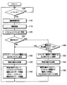
- the control device 2 uses the real A area 51a, the real B area 51b, the history C area 52, and the history B area 53 to execute the process shown in the flowchart of FIG.
- the control device 2 functions as the bird's-eye conversion unit 21, the image composition unit 22, the vehicle motion calculation unit 23, and the shadow determination unit 24 by executing the processing of FIG.
- FIG. 3 The process of FIG. 3 will be described along one example. In this case, it is assumed that no shadow other than the shadow of the host vehicle is captured in the captured image of the in-vehicle camera 1.
- the real A area 51 a, the real B area 51 b, the history C area 52, and the history B area 53 each include the bird's-eye image data. It is an empty state, in other words, only the data indicating the sky is included.
- the control device 2 determines whether or not the shift position of the host vehicle is reverse (reverse position) based on the latest shift range information that has been input. Execute.
- step 105 the shift position is reverse, and proceeds to step 110.
- step 110 one input of the latest photographed image is received from the in-vehicle camera 1 and acquired.
- step 115 a known bird's-eye conversion is performed on the latest photographed image acquired in the immediately preceding step 110.
- the captured image is converted into a bird's-eye view image of a viewpoint looking down from the information of the own vehicle (directly or diagonally below).
- the conversion formula used for the bird's eye conversion is recorded in advance in a memory (for example, ROM) of the control device 2.
- the control device 2 functions as the bird's eye conversion unit 21 by executing the process of step 115.
- step 120 the bird's-eye view image created in the immediately preceding step 115 is stored in the real A area 51a and the real B area 51b in the memory.
- an image in a predetermined range farther from the vehicle out of the bird's-eye view image divided in two in the front-rear direction of the vehicle is stored in the real A area 51a, and the bird's-eye image is similarly divided into two.
- an image in a predetermined range closer to the vehicle is stored in the real B area 51b.
- step 125 it is determined whether or not there is a shadow in the bird's-eye view image saved in the real B area 51b among the bird's-eye view images created in the previous step 115.
- Whether or not a shadow exists in the bird's-eye view image may be determined by a known method (for example, the method described in Patent Document 2 or Non-Patent Document 1). For example, it can be determined using the shadow detection technique described in Patent Document 2.
- the partial area of the bird's-eye view image in the real B area 51b is divided based on the hue and the luminance, and the difference in hue is equal to or less than a predetermined threshold among the divided areas. Two regions that are present and have a predetermined difference in luminance are extracted.
- the higher luminance is defined as a non-shadow region
- the lower luminance is defined as a shadow region.
- a vector from the shadow area to the non-shadow area in the color information space is specified as the color information of the light source.
- the entire area of the bird's-eye view image in the real B area 51b is divided based on the hue and luminance, and when the difference in hue between adjacent areas matches the hue of the light source within a predetermined range, Among the adjacent areas, the lower luminance is specified as a shadow.
- the control device 2 functions as the shadow determination unit 24 by executing the process of step 125.
- step 125 it is determined in step 125 that there is a shadow, and the process proceeds to step 145.
- step 145 it is determined whether or not there is a predetermined amount or more of bird's-eye image data in the history B area 53. For example, when all of the history B area 53 is filled with the bird's-eye image data, it is determined that there is a predetermined amount or more of the bird's-eye image data in the history B area 53; Alternatively, it may be determined that the data of the bird's-eye view image is less than a predetermined amount.
- step 130 the images of the real A area 51a, the real B area 51b, and the history C area 52 are connected and combined in the arrangement as shown on the left side of FIG. It is stored in a predetermined output memory.
- the vehicle shape image 54 may be transparently superimposed so that both the synthesized bird's-eye image and the vehicle shape image 54 are visible at a portion where the synthesized bird's-eye image and the vehicle shape image 54 overlap.
- the control device 2 functions as the image composition unit 22 by executing the process of step 130.
- the synthesized bird's-eye image stored in the output memory is input from the control device 2 to the image display device 3, and as a result, the image display device 3 displays the synthesized bird's-eye image on the driver.
- step 135 various vehicle behavior information input from the host vehicle, that is, shift range information, vehicle speed information, and the latest information on the steering angle (or yaw rate) (using past information additionally) are used. Based on this, the movement amount (movement vector and attitude change angle) of the host vehicle according to the well-known Ackerman model is calculated. Note that the amount of movement referred to here is the amount of movement indicating the movement of the vehicle during the period from the previous captured image acquisition timing to the current captured image acquisition timing (ie, the amount of movement at the captured image acquisition interval). .
- the control device 2 functions as the vehicle motion calculation unit 23 by executing the process of step 135.
- step 140 how the surroundings of the host vehicle (assumed to be fixed on the road surface) move relative to the host vehicle based on the amount of movement of the host vehicle calculated in the previous step 135.
- the relative movement amount indicating whether to do is calculated.
- a movement opposite to the movement amount of the own vehicle calculated in the immediately preceding step 135 is calculated.
- the movement vector of the host vehicle is ( ⁇ , ⁇ ) and the posture change angle is ⁇
- the movement vector is ( ⁇ , ⁇ ) and the posture change angle is the amount of relative movement around the host vehicle. Is - ⁇ .
- step 140 the real A area 51a and the history B area 53 are connected in the arrangement shown in the right side of FIG. 2 (note that the history C area 52 is not connected) as described above.
- the bird's-eye view image is moved according to the relative relative movement amount calculated in the above manner. Therefore, as the vehicle moves backward, the bird's-eye view image increases in the history C area 52 that was empty at the beginning of the process of FIG.
- a bird's-eye view image from the real A area 51a to the history B area 53 or from the history B area 53 to the real A area 51a at the boundary between the real A area 51a and the history B area 53.
- the vehicle is moving backward, so the former is used. Therefore, as the vehicle moves backward, the bird's-eye view image increases in the history B area 53 that was empty at the beginning of the process of FIG.
- step 140 the process returns to step 105. Thereafter, it is assumed that the vehicle continues to move backward and the shadow of the own vehicle continues to be in the latest captured image (in the position corresponding to the real B area 51b). In this case, while the data of the bird's-eye view image in the history B area 53 is less than the predetermined amount, the control device 2 determines that the shift position is reverse in step 105, determines that there is a shadow in step 125, In step 145, it is determined that the data of the bird's-eye view image is less than a predetermined amount in the history B area 53.
- control device 2 repeatedly executes steps 105, 110, 115, 120, 125, 145, 130, 135, and 140 in this order.
- the processing contents of each step are the same as those already described.
- the bird's-eye view image in the real B area 51b is gradually accumulated in the history C area 52 in accordance with the backward movement of the vehicle (either straight backward or curved and backward). It will be done.
- the synthesized bird's-eye image (and the vehicle image 54) obtained by connecting the bird's-eye images in the real A area 51a, the real B area 51b, and the history C area 52 is displayed in the image display device 3. Will continue to be displayed.
- control device 2 repeatedly executes steps 105, 110, 115, 120, 125, 145, 130, 135, and 140 in this order, so that the vehicle can be moved backward (either straight forward or curved and backward). Accordingly, the bird's-eye view image in the real A area 51 a is gradually accumulated in the history B area 53. However, during this time, the history B area 53 is not used for display on the image display device 3.
- the real A area 51a stores a bird's-eye view image at a rear position farther from the rear end of the vehicle than the real B area 51b (for example, a rearward distance of 3 meters or more from the rear end of the host vehicle). Therefore, the possibility that the shadow of the host vehicle is reflected in the bird's-eye view image in the real A area 51a is relatively low. In this example, it is assumed that the shadow of the own vehicle is not reflected in the bird's-eye view image in the real A area 51a. Therefore, the shadow of the host vehicle is not reflected in the bird's-eye view image that moves from the real A area 51 a and accumulates in the history B area 53.
- the bird's-eye image data in the history B area 53 becomes Suppose that it becomes more than a predetermined amount.
- control device 2 determines that the shift position is reverse in step 105, determines that there is a shadow in step 125, and proceeds to step 145, but in step 145, the bird's-eye view image in the history B region 53 is determined. Since it is determined that the data is greater than or equal to the predetermined amount, the process proceeds to step 150.
- step 150 the images of the real A area 51a, the history B area 53, and the history C area 52 are connected and combined in the arrangement as shown on the right side of FIG. It is stored in a predetermined output memory.
- step 150 is different from step 130 in that the history B area 53 (without shadow) is used instead of the real B area 51b (with shadow). Note that an image 54 indicating the shape of the host vehicle may be superimposed on the synthesized bird's-eye image, as in step 130.
- the control device 2 functions as the image composition unit 22 by executing the processing of step 150.
- the synthesized bird's-eye image stored in the output memory is input from the control device 2 to the image display device 3, and as a result, the image display device 3 displays the synthesized bird's-eye image on the driver.
- step 155 the amount of movement (movement vector and attitude change angle) of the vehicle according to the well-known Ackerman model is calculated by the same method as in step 130.
- the control device 2 functions as the vehicle motion calculation unit 23 by executing the process of step 155.
- step 160 how the surroundings of the host vehicle (assumed to be fixed on the road surface) move relative to the host vehicle based on the movement amount of the host vehicle calculated in the immediately preceding step 155.
- a relative movement amount indicating whether or not to perform is calculated by the same method as in step 140.
- a bird's-eye view image from the real A area 51a to the history B area 53 or from the history B area 53 to the real A area 51a at the boundary between the real A area 51a and the history B area 53.
- the vehicle is moving backward, so the former is used. Therefore, as the vehicle moves backward, the bird's-eye view image increases in the history B area 53 that was empty at the beginning of the process of FIG.
- the bird's-eye view image from the history B region 53 to the history C region 52 or from the history C region 52 to the history B region 53 at the boundary between the history B region 53 and the history C region 52.
- the vehicle is moving backward, so the former is used.
- the shadow image of the own vehicle does not move in the history C area 52.
- step 160 the process returns to step 105. Thereafter, it is assumed that the vehicle continues to move backward and the shadow of the own vehicle continues to be in the latest captured image (in the position corresponding to the real B area 51b). In this case, the control device 2 determines that the shift position is reverse in step 105, determines that there is a shadow in step 125, and in step 145, the data of the bird's-eye image is greater than or equal to a predetermined amount in the history B area 53. Is determined.
- control device 2 repeatedly executes steps 105, 110, 115, 120, 125, 145, 150, 155, and 160 in this order.
- the processing contents of each step are the same as those already described.
- the bird's-eye view image in the real A area 51a gradually accumulates in the history B area 53 in accordance with the backward movement of the vehicle (which may be straight forward or curved and reverse).
- the bird's-eye view image in the history B area 53 is gradually accumulated in the history C area 52.
- step 150 the synthesized bird's-eye image (and the vehicle image 54) obtained by connecting the bird's-eye images in the real A area 51a, the history B area 53, and the history C area 52 is displayed in the image display device 3. Will continue to be displayed.
- step 125 determines in step 125 that there is no shadow in the bird's-eye view image created in the immediately preceding step 115, and proceeds to step 130.
- steps 130, 135, and 140 are as already described.
- the shadow image does not move from the real B area 51b to the history C area 52 in step 140.
- the control device 2 determines in step 125 that there is no shadow, so steps 105, 110, and 120 are performed. , 125, 130, 135, 140 are repeated. Also in this case, since there is no shadow in the bird's-eye view image in the real B area 51b, the shadow image does not move from the real B area 51b to the history C area 52.
- the display range using the latest photographed image is displayed by using the bird's-eye image in the real B area 51b instead of the history B area 53 for display.
- the shadow of the host vehicle was already in the captured image when the processing of FIG. 3 started.
- the shadow of the own vehicle appears in the captured image because the shadow of the own vehicle is not included in the captured image at the time when the processing of FIG. .
- Step 105 Since the control device 2 determines that there is no shadow in Step 125 while the vehicle is moving back without the shadow of the own vehicle being included in the bird's-eye view image in the real B area 51b, Step 105, The processing of 110, 120, 125, 130, 135, 140 is repeated. In this case, since there is no shadow in the bird's-eye view image in the real B area 51b, the shadow image does not move from the real B area 51b to the history C area 52. In this case, in step 140, bird's-eye images are gradually accumulated from the real A area 51a to the history B area 53 as the vehicle moves backward.
- the control device 2 determines that there is a shadow in step 125, determines in step 145 that the bird's-eye image data is greater than or equal to the predetermined amount in the history B area 53, and proceeds to step 150. , 160 are executed in the same manner as already described.
- the control device 2 Even after that, even if there is a shadow in the captured image (specifically, in the captured image in the range corresponding to the real B area 51b), the control device 2 thereafter performs steps 105, 110, 115, 120, 125. 145, 150, 155, and 160 are repeatedly executed in this order, so that the latest captured image in the real B area 51b is not used, but the captured image in the history B area 53 is used.
- the composite image obtained by connecting the bird's-eye images in the B area 53 and the history C area 52 has no shadow at all.
- step 125 it is determined whether or not there is a shadow in the bird's-eye view image in the real B area 51b created in the previous step 115. However, it is not determined whether the shadow is the shadow of the own vehicle or the shadow of another object.
- the control device 2 does not change the shadow of the other object in the bird's-eye image in the latest real B area 51b.
- the same operation is performed as when the shadow of is in the bird's-eye view image in the latest real B area 51b.
- step 125 if it is determined in step 125 that there is a shadow, and if a predetermined amount or more of bird's-eye image data is accumulated in the history B region 53, the history B region 53 is used instead of the real B region 51b, FIG.
- the combined bird's-eye view image displayed in the right-side arrangement is displayed, and this combined bird's-eye view image is moved in the real A area 51a, the history B area 53, and the history C area 52 in accordance with the movement of the vehicle.
- a history B area 53 is provided, and the history B area 53 is used by using the bird's eye image stored in the real A area 51a so that the bird's eye view image in the history B area 53 reflects the current surrounding arrangement of the vehicle.
- a bird's-eye view image is formed in the region 53.
- the bird's-eye view image stored in a predetermined region including part or all of the real B region 51b reflects the current surrounding arrangement of the vehicle. If there is no shadow, the bird's-eye view image stored in the real B area 51b is used to form a bird's-eye view image in the history C area 52. If there is a shadow, the image is saved in the history B area 53. A bird's-eye view image is formed in the history C area 52 using the bird's-eye view image.
- history synthesis is performed using the bird's-eye image of the history B area 53 configured based on the bird's-eye image of the real A area 51a (an image with a high possibility of having no shadow).
- the possibility that the shadow of the host vehicle is enlarged in the region 52 can be reduced.
- the history B area 53 is stored in steps 150 to 160.
- the real B region 51b is used to move the bird's-eye image to the display and history C region 52 in steps 130-140.
- history B area 53 is displayed when a sufficient amount of bird's eye images are not accumulated in the history B area 53 even if there is a shadow in the bird's eye image of the real B area 51b. If used, a blank is generated in the synthesized bird's-eye image displayed on the image display device 3, and the blank is moved to the history C area 52.
- the control device 2 functions as an example of an acquisition device by executing Step 110, functions as an example of a bird's eye conversion device by executing Step 115, and executes Step 120. It functions as an example of a divided storage device, functions as an example of a shadow determination device by executing step 125, functions as an example of a motion calculation device by executing steps 135 and 155, and executes steps 130 and 150 Thus, it functions as an example of the first display control device by executing step 130, functions as an example of the first history image construction device by executing step 140, and step 150.
- the second history servess as an example of an image configuration device, functions as an example of a data amount determination unit by executing step 145.
- step 145 it may be replaced with a determination whether the vehicle has moved backward by a predetermined distance or more (or whether the vehicle has moved backward by a predetermined time or more). This is an operation based on the idea that if the vehicle moves backward by a sufficient distance, the history B area 53 should contain a sufficient amount of bird's-eye view conversion data.
- step 125 of the above embodiment it is not determined whether the shadow is from the own vehicle. If there is a shadow in the real B area 51b, even if it is a shadow of an object other than the own vehicle, If it exists in B area
- the in-vehicle camera 1 repeatedly captures a predetermined range behind the vehicle, but the in-vehicle camera 1 repeatedly captures a predetermined range in front of the vehicle. May be. In that case, in the said specification, it will read as replacing the front and back of a vehicle.
- step 140 based on the amount of movement of the vehicle, the bird's-eye view image is moved within the combined area where the real A area 51a, the real B area 51b, and the history C area 52c are connected. At the same time, the bird's-eye view image is moved within the combined area obtained by connecting the history B area 53 and the real A area 51a.
- the bird's-eye view image at each position in the history C area 52 is a bird's-eye image immediately before the position deviates from the shooting range of the in-vehicle camera 1 (immediately before deviating from the real B area 51b).
- this is not necessarily the case.
- the bird's-eye view image at each position in the history C area 52 may be a bird's-eye view image before the position immediately before the position is out of the shooting range of the in-vehicle camera 1.
- step 140 the history C area 52 is stored in the real B area 51b based on the amount of movement of the vehicle so that the bird's-eye view image in the history C area 52 reflects the current surrounding arrangement of the vehicle. It is sufficient if it is configured using a bird's-eye view image.
- step 160 based on the amount of movement of the vehicle, the bird's-eye view image is moved within the combined area obtained by connecting the real A area 51a, the history B area 53, and the history C area 52c. It is like that.
- the bird's-eye view image at each position in the history C area 52 is a bird's-eye view image immediately before the position deviates from the history B area 53.
- this is not necessarily the case.
- the bird's-eye view image at each position in the history C area 52 may be a bird's-eye image that is further before the position immediately before the position deviates from the history B area 53.
- step 160 the history C area 52 is stored in the history B area 53 based on the amount of movement of the vehicle so that the bird's-eye view image in the history C area 52 reflects the current surrounding arrangement of the vehicle. It is sufficient if it is configured using a bird's-eye view image.
- step 140 the bird's-eye view image is moved within the combined area where the real A area 51a and the history B area 53 are connected based on the amount of movement of the vehicle.
- step 160 the bird's-eye view image is moved in the combined area obtained by connecting the real A area 51a, the history B area 53, and the history C area 52c based on the amount of movement of the vehicle.
- the bird's-eye view image at each position in the history B area 53 is a bird's-eye view image immediately before the position deviates from the real A area 51a.
- the bird's-eye view image at each position in the history B area 53 may be a bird's-eye view image before the position immediately before the position deviates from the real A area 51a.
- the bird's-eye view image in the history B area 53 is stored in the real A area 51a based on the amount of movement of the vehicle so that the bird's-eye view image in the history B area 53 reflects the current surrounding arrangement of the vehicle. It is sufficient if it is configured using a bird's-eye view image.
- the following two effects (a) and (b) can be obtained by providing the history B region 53.
- step 150 as in step 130, the synthesized image of the bird's-eye view images in the real A area 51a, the real B area 51b, and the history C area 52 is stored in the output memory. May be.
Landscapes
- Physics & Mathematics (AREA)
- General Physics & Mathematics (AREA)
- Engineering & Computer Science (AREA)
- Theoretical Computer Science (AREA)
- Closed-Circuit Television Systems (AREA)
- Image Processing (AREA)
- Traffic Control Systems (AREA)
- Image Analysis (AREA)
- Controls And Circuits For Display Device (AREA)
Priority Applications (3)
| Application Number | Priority Date | Filing Date | Title |
|---|---|---|---|
| CN201380026870.XA CN104335241B (zh) | 2012-05-23 | 2013-03-08 | 车辆周围图像显示控制装置、显示方法及图像处理方法 |
| EP13793824.7A EP2854098B1 (en) | 2012-05-23 | 2013-03-08 | Vehicle surroundings image display control device, vehicle surroundings image display control method, non-transitory tangible computer-read medium comprising command containing said method, and image processing method effecting top-view conversion and display of image of vehicle surroundings |
| US14/395,514 US20150070394A1 (en) | 2012-05-23 | 2013-03-08 | Vehicle surrounding image display control device, vehicle surrounding image display control method, non-transitory tangible computer-readable medium comprising command including the method, and image processing method executing top view conversion and display of image of vehicle surroundings |
Applications Claiming Priority (2)
| Application Number | Priority Date | Filing Date | Title |
|---|---|---|---|
| JP2012117762A JP6003226B2 (ja) | 2012-05-23 | 2012-05-23 | 車両周囲画像表示制御装置および車両周囲画像表示制御プログラム |
| JP2012-117762 | 2012-05-23 |
Publications (1)
| Publication Number | Publication Date |
|---|---|
| WO2013175684A1 true WO2013175684A1 (ja) | 2013-11-28 |
Family
ID=49623400
Family Applications (1)
| Application Number | Title | Priority Date | Filing Date |
|---|---|---|---|
| PCT/JP2013/001489 Ceased WO2013175684A1 (ja) | 2012-05-23 | 2013-03-08 | 車両周囲画像表示制御装置、車両周囲画像表示制御方法、当該方法を含む命令からなる持続的有形コンピュータ読み取り媒体、車両の周囲の画像をトップビュー変換して表示させる画像処理方法 |
Country Status (5)
| Country | Link |
|---|---|
| US (1) | US20150070394A1 (https=) |
| EP (1) | EP2854098B1 (https=) |
| JP (1) | JP6003226B2 (https=) |
| CN (1) | CN104335241B (https=) |
| WO (1) | WO2013175684A1 (https=) |
Cited By (2)
| Publication number | Priority date | Publication date | Assignee | Title |
|---|---|---|---|---|
| JP2017037310A (ja) * | 2015-08-12 | 2017-02-16 | 有限会社ヴェルク・ジャパン | 歴史画像と現在画像の合成及び音声ガイドの表現方法。 |
| WO2018070338A1 (ja) * | 2016-10-14 | 2018-04-19 | 株式会社デンソー | 表示制御装置 |
Families Citing this family (23)
| Publication number | Priority date | Publication date | Assignee | Title |
|---|---|---|---|---|
| JP5994437B2 (ja) * | 2012-07-04 | 2016-09-21 | 株式会社デンソー | 車両周囲画像表示制御装置および車両周囲画像表示制御プログラム |
| JP6327115B2 (ja) * | 2014-11-04 | 2018-05-23 | 株式会社デンソー | 車両周辺画像表示装置、車両周辺画像表示方法 |
| KR102426631B1 (ko) * | 2015-03-16 | 2022-07-28 | 현대두산인프라코어 주식회사 | 건설 기계의 사각 영역 표시 방법 및 이를 수행하기 위한 장치 |
| JP6464846B2 (ja) | 2015-03-17 | 2019-02-06 | 株式会社デンソー | 車両周囲画像表示制御装置、および車両周囲画像表示制御プログラム |
| JP6464952B2 (ja) | 2015-08-04 | 2019-02-06 | 株式会社デンソー | 表示制御装置、表示制御プログラム及び表示制御方法 |
| JP6519409B2 (ja) * | 2015-08-27 | 2019-05-29 | 株式会社デンソー | 車両周辺画像表示制御装置及び車両周辺画像表示制御プログラム |
| JP6493143B2 (ja) * | 2015-10-15 | 2019-04-03 | 株式会社デンソー | 表示制御装置及び表示制御プログラム |
| JP6477444B2 (ja) | 2015-11-25 | 2019-03-06 | 株式会社デンソー | 表示制御装置及び表示制御プログラム |
| JP2017117315A (ja) * | 2015-12-25 | 2017-06-29 | 株式会社デンソー | 表示制御装置 |
| JP6565693B2 (ja) * | 2016-01-12 | 2019-08-28 | 株式会社デンソー | 車載カメラのレンズ異常検出装置 |
| CN105774657B (zh) * | 2016-04-14 | 2020-03-17 | 广州市晶华精密光学股份有限公司 | 一种单摄像头全景倒车影像系统 |
| CN105763854B (zh) * | 2016-04-18 | 2019-01-08 | 扬州航盛科技有限公司 | 一种基于单目摄像头的全景成像系统及其成像方法 |
| US10325163B2 (en) * | 2016-11-22 | 2019-06-18 | Ford Global Technologies, Llc | Vehicle vision |
| JP6720931B2 (ja) * | 2017-07-14 | 2020-07-08 | 株式会社デンソー | 車両周囲認識装置 |
| US10579067B2 (en) * | 2017-07-20 | 2020-03-03 | Huawei Technologies Co., Ltd. | Method and system for vehicle localization |
| KR102051211B1 (ko) * | 2018-03-29 | 2019-12-02 | 주식회사평화발레오 | 펄크럼 링 센터링 기능을 구비한 클러치 어셈블리 |
| GB2573792B (en) * | 2018-05-17 | 2022-11-09 | Denso Corp | Surround monitoring system for vehicles |
| IL265818A (en) * | 2019-04-02 | 2020-10-28 | Ception Tech Ltd | System and method for determining location and orientation of an object in a space |
| JP2022112431A (ja) * | 2021-01-21 | 2022-08-02 | 京セラ株式会社 | 電子機器、電子機器の制御方法、及びプログラム |
| DE102021212154A1 (de) | 2021-10-27 | 2023-04-27 | Robert Bosch Gesellschaft mit beschränkter Haftung | Verfahren zum Generieren einer Darstellung eines verdeckten Bereiches einer Umgebung einer mobilen Plattform |
| WO2023202844A1 (de) | 2022-04-19 | 2023-10-26 | Continental Autonomous Mobility Germany GmbH | Verfahren für ein kamerasystem sowie kamerasystem |
| DE102022206328B3 (de) | 2022-04-19 | 2023-02-09 | Continental Autonomous Mobility Germany GmbH | Verfahren für ein Kamerasystem sowie Kamerasystem |
| CN116373745A (zh) * | 2023-05-18 | 2023-07-04 | 蔚来汽车科技(安徽)有限公司 | 辅助驾驶中盲区透明显示方法、系统、电子设备及存储介质 |
Citations (4)
| Publication number | Priority date | Publication date | Assignee | Title |
|---|---|---|---|---|
| JP2002373327A (ja) | 2001-06-13 | 2002-12-26 | Denso Corp | 車両周辺画像処理装置及び記録媒体 |
| JP2007300559A (ja) * | 2006-05-02 | 2007-11-15 | Alpine Electronics Inc | 車両周辺画像提供装置及び車両周辺画像における影補正方法 |
| WO2009057410A1 (ja) * | 2007-10-30 | 2009-05-07 | Nec Corporation | 路面標示画像処理装置,路面標示画像処理方法及びプログラム |
| JP2010237976A (ja) | 2009-03-31 | 2010-10-21 | Kyushu Institute Of Technology | 光源情報取得装置、陰影検出装置、陰影除去装置、それらの方法、及びプログラム |
Family Cites Families (9)
| Publication number | Priority date | Publication date | Assignee | Title |
|---|---|---|---|---|
| US6515597B1 (en) * | 2000-01-31 | 2003-02-04 | Matsushita Electric Industrial Co. Ltd. | Vicinity display for car |
| JP3300337B2 (ja) * | 2000-04-28 | 2002-07-08 | 松下電器産業株式会社 | 画像処理装置および監視システム |
| US6734896B2 (en) * | 2000-04-28 | 2004-05-11 | Matsushita Electric Industrial Co., Ltd. | Image processor and monitoring system |
| JP4321543B2 (ja) * | 2006-04-12 | 2009-08-26 | トヨタ自動車株式会社 | 車両周辺監視装置 |
| JP4309920B2 (ja) * | 2007-01-29 | 2009-08-05 | 株式会社東芝 | 車載用ナビゲーション装置、路面標示識別プログラム及び路面標示識別方法 |
| JP4770755B2 (ja) * | 2007-02-26 | 2011-09-14 | 株式会社デンソー | 道路標示認識装置 |
| JP2008219063A (ja) * | 2007-02-28 | 2008-09-18 | Sanyo Electric Co Ltd | 車両周辺監視装置及び方法 |
| JP5222597B2 (ja) * | 2008-03-19 | 2013-06-26 | 三洋電機株式会社 | 画像処理装置及び方法、運転支援システム、車両 |
| JP5872764B2 (ja) * | 2010-12-06 | 2016-03-01 | 富士通テン株式会社 | 画像表示システム |
-
2012
- 2012-05-23 JP JP2012117762A patent/JP6003226B2/ja active Active
-
2013
- 2013-03-08 CN CN201380026870.XA patent/CN104335241B/zh not_active Expired - Fee Related
- 2013-03-08 EP EP13793824.7A patent/EP2854098B1/en not_active Not-in-force
- 2013-03-08 US US14/395,514 patent/US20150070394A1/en not_active Abandoned
- 2013-03-08 WO PCT/JP2013/001489 patent/WO2013175684A1/ja not_active Ceased
Patent Citations (5)
| Publication number | Priority date | Publication date | Assignee | Title |
|---|---|---|---|---|
| JP2002373327A (ja) | 2001-06-13 | 2002-12-26 | Denso Corp | 車両周辺画像処理装置及び記録媒体 |
| US20030165255A1 (en) | 2001-06-13 | 2003-09-04 | Hirohiko Yanagawa | Peripheral image processor of vehicle and recording medium |
| JP2007300559A (ja) * | 2006-05-02 | 2007-11-15 | Alpine Electronics Inc | 車両周辺画像提供装置及び車両周辺画像における影補正方法 |
| WO2009057410A1 (ja) * | 2007-10-30 | 2009-05-07 | Nec Corporation | 路面標示画像処理装置,路面標示画像処理方法及びプログラム |
| JP2010237976A (ja) | 2009-03-31 | 2010-10-21 | Kyushu Institute Of Technology | 光源情報取得装置、陰影検出装置、陰影除去装置、それらの方法、及びプログラム |
Non-Patent Citations (2)
| Title |
|---|
| MICHITAKA NISHIMOTO; TAKASHI IZUMI: "for vehicle detection based on shadow extraction", ELECTRICAL ENGINEERS ITS STUDY GROUP, June 2006 (2006-06-01), pages 7 - 12 |
| See also references of EP2854098A4 |
Cited By (2)
| Publication number | Priority date | Publication date | Assignee | Title |
|---|---|---|---|---|
| JP2017037310A (ja) * | 2015-08-12 | 2017-02-16 | 有限会社ヴェルク・ジャパン | 歴史画像と現在画像の合成及び音声ガイドの表現方法。 |
| WO2018070338A1 (ja) * | 2016-10-14 | 2018-04-19 | 株式会社デンソー | 表示制御装置 |
Also Published As
| Publication number | Publication date |
|---|---|
| EP2854098B1 (en) | 2018-09-19 |
| EP2854098A1 (en) | 2015-04-01 |
| CN104335241B (zh) | 2017-04-12 |
| JP6003226B2 (ja) | 2016-10-05 |
| US20150070394A1 (en) | 2015-03-12 |
| JP2013246493A (ja) | 2013-12-09 |
| CN104335241A (zh) | 2015-02-04 |
| EP2854098A4 (en) | 2016-03-09 |
Similar Documents
| Publication | Publication Date | Title |
|---|---|---|
| WO2013175684A1 (ja) | 車両周囲画像表示制御装置、車両周囲画像表示制御方法、当該方法を含む命令からなる持続的有形コンピュータ読み取り媒体、車両の周囲の画像をトップビュー変換して表示させる画像処理方法 | |
| US9633266B2 (en) | Image processing apparatus and method that synthesizes an all-round image of a vehicle's surroundings | |
| US10896542B2 (en) | Moving body image generation recording display device and program product | |
| JP6471522B2 (ja) | カメラパラメータ調整装置 | |
| JP5994437B2 (ja) | 車両周囲画像表示制御装置および車両周囲画像表示制御プログラム | |
| JP7000383B2 (ja) | 画像処理装置および画像処理方法 | |
| JP2007274377A (ja) | 周辺監視装置、プログラム | |
| JP2017069852A (ja) | 情報表示装置及び情報表示方法 | |
| JP2014129093A (ja) | 車両用周辺監視装置 | |
| CN106063258A (zh) | 车辆周边图像显示装置、车辆周边图像显示方法 | |
| US10873725B2 (en) | Display control device | |
| CN107077715B (zh) | 车辆周边图像显示装置、车辆周边图像显示方法 | |
| JP6411100B2 (ja) | 車両周囲画像生成装置および車両周囲画像生成方法 | |
| EP3396620B1 (en) | Display control device and display control method | |
| JP6519409B2 (ja) | 車両周辺画像表示制御装置及び車両周辺画像表示制御プログラム | |
| JP6464846B2 (ja) | 車両周囲画像表示制御装置、および車両周囲画像表示制御プログラム | |
| WO2017022457A1 (ja) | 表示制御装置、表示制御方法、及び表示制御プログラム | |
| KR101949961B1 (ko) | 운전 보조 장치 및 방법 | |
| JP2018207448A (ja) | 画像作成装置 | |
| KR20180069380A (ko) | 운전 보조 장치 및 방법 |
Legal Events
| Date | Code | Title | Description |
|---|---|---|---|
| 121 | Ep: the epo has been informed by wipo that ep was designated in this application |
Ref document number: 13793824 Country of ref document: EP Kind code of ref document: A1 |
|
| WWE | Wipo information: entry into national phase |
Ref document number: 14395514 Country of ref document: US |
|
| WWE | Wipo information: entry into national phase |
Ref document number: 2013793824 Country of ref document: EP |
|
| NENP | Non-entry into the national phase |
Ref country code: DE |