WO2013175630A1 - 操作装置、情報処理システム、および通信方法 - Google Patents
操作装置、情報処理システム、および通信方法 Download PDFInfo
- Publication number
- WO2013175630A1 WO2013175630A1 PCT/JP2012/063495 JP2012063495W WO2013175630A1 WO 2013175630 A1 WO2013175630 A1 WO 2013175630A1 JP 2012063495 W JP2012063495 W JP 2012063495W WO 2013175630 A1 WO2013175630 A1 WO 2013175630A1
- Authority
- WO
- WIPO (PCT)
- Prior art keywords
- data
- information processing
- sensor
- communication
- controller device
- Prior art date
Links
- 230000010365 information processing Effects 0.000 title claims abstract description 809
- 230000006854 communication Effects 0.000 title claims abstract description 646
- 238000004891 communication Methods 0.000 title claims abstract description 645
- 238000000034 method Methods 0.000 title claims description 204
- 230000001133 acceleration Effects 0.000 claims abstract description 147
- 238000012545 processing Methods 0.000 claims description 96
- 238000001514 detection method Methods 0.000 claims description 65
- 230000005540 biological transmission Effects 0.000 description 279
- 230000008569 process Effects 0.000 description 146
- 238000013523 data management Methods 0.000 description 112
- 238000007726 management method Methods 0.000 description 61
- 230000004048 modification Effects 0.000 description 53
- 238000012986 modification Methods 0.000 description 53
- 230000006870 function Effects 0.000 description 41
- 230000004913 activation Effects 0.000 description 39
- 230000006835 compression Effects 0.000 description 39
- 238000007906 compression Methods 0.000 description 39
- 230000000694 effects Effects 0.000 description 27
- 230000006837 decompression Effects 0.000 description 25
- 238000010586 diagram Methods 0.000 description 15
- 238000003860 storage Methods 0.000 description 15
- 239000003550 marker Substances 0.000 description 14
- 230000002093 peripheral effect Effects 0.000 description 11
- 230000004044 response Effects 0.000 description 11
- 210000003811 finger Anatomy 0.000 description 9
- 230000033001 locomotion Effects 0.000 description 9
- 230000008859 change Effects 0.000 description 8
- 238000012790 confirmation Methods 0.000 description 6
- 238000004364 calculation method Methods 0.000 description 5
- 238000005070 sampling Methods 0.000 description 5
- 230000001360 synchronised effect Effects 0.000 description 5
- 238000009434 installation Methods 0.000 description 4
- 239000011159 matrix material Substances 0.000 description 3
- 230000005236 sound signal Effects 0.000 description 3
- 238000011144 upstream manufacturing Methods 0.000 description 3
- 238000006243 chemical reaction Methods 0.000 description 2
- 238000013144 data compression Methods 0.000 description 2
- 230000003111 delayed effect Effects 0.000 description 2
- 238000003384 imaging method Methods 0.000 description 2
- 238000003825 pressing Methods 0.000 description 2
- 230000008054 signal transmission Effects 0.000 description 2
- 239000007787 solid Substances 0.000 description 2
- 125000002066 L-histidyl group Chemical group [H]N1C([H])=NC(C([H])([H])[C@](C(=O)[*])([H])N([H])[H])=C1[H] 0.000 description 1
- 230000003213 activating effect Effects 0.000 description 1
- 230000001174 ascending effect Effects 0.000 description 1
- 238000005520 cutting process Methods 0.000 description 1
- 230000006866 deterioration Effects 0.000 description 1
- 238000005516 engineering process Methods 0.000 description 1
- 238000012905 input function Methods 0.000 description 1
- 239000004973 liquid crystal related substance Substances 0.000 description 1
- 230000005389 magnetism Effects 0.000 description 1
- 238000004519 manufacturing process Methods 0.000 description 1
- 210000003813 thumb Anatomy 0.000 description 1
Images


Classifications
-
- A—HUMAN NECESSITIES
- A63—SPORTS; GAMES; AMUSEMENTS
- A63F—CARD, BOARD, OR ROULETTE GAMES; INDOOR GAMES USING SMALL MOVING PLAYING BODIES; VIDEO GAMES; GAMES NOT OTHERWISE PROVIDED FOR
- A63F13/00—Video games, i.e. games using an electronically generated display having two or more dimensions
- A63F13/40—Processing input control signals of video game devices, e.g. signals generated by the player or derived from the environment
- A63F13/42—Processing input control signals of video game devices, e.g. signals generated by the player or derived from the environment by mapping the input signals into game commands, e.g. mapping the displacement of a stylus on a touch screen to the steering angle of a virtual vehicle
-
- A—HUMAN NECESSITIES
- A63—SPORTS; GAMES; AMUSEMENTS
- A63F—CARD, BOARD, OR ROULETTE GAMES; INDOOR GAMES USING SMALL MOVING PLAYING BODIES; VIDEO GAMES; GAMES NOT OTHERWISE PROVIDED FOR
- A63F13/00—Video games, i.e. games using an electronically generated display having two or more dimensions
- A63F13/20—Input arrangements for video game devices
- A63F13/21—Input arrangements for video game devices characterised by their sensors, purposes or types
- A63F13/211—Input arrangements for video game devices characterised by their sensors, purposes or types using inertial sensors, e.g. accelerometers or gyroscopes
-
- A—HUMAN NECESSITIES
- A63—SPORTS; GAMES; AMUSEMENTS
- A63F—CARD, BOARD, OR ROULETTE GAMES; INDOOR GAMES USING SMALL MOVING PLAYING BODIES; VIDEO GAMES; GAMES NOT OTHERWISE PROVIDED FOR
- A63F13/00—Video games, i.e. games using an electronically generated display having two or more dimensions
- A63F13/20—Input arrangements for video game devices
- A63F13/21—Input arrangements for video game devices characterised by their sensors, purposes or types
- A63F13/214—Input arrangements for video game devices characterised by their sensors, purposes or types for locating contacts on a surface, e.g. floor mats or touch pads
- A63F13/2145—Input arrangements for video game devices characterised by their sensors, purposes or types for locating contacts on a surface, e.g. floor mats or touch pads the surface being also a display device, e.g. touch screens
-
- A—HUMAN NECESSITIES
- A63—SPORTS; GAMES; AMUSEMENTS
- A63F—CARD, BOARD, OR ROULETTE GAMES; INDOOR GAMES USING SMALL MOVING PLAYING BODIES; VIDEO GAMES; GAMES NOT OTHERWISE PROVIDED FOR
- A63F13/00—Video games, i.e. games using an electronically generated display having two or more dimensions
- A63F13/20—Input arrangements for video game devices
- A63F13/21—Input arrangements for video game devices characterised by their sensors, purposes or types
- A63F13/217—Input arrangements for video game devices characterised by their sensors, purposes or types using environment-related information, i.e. information generated otherwise than by the player, e.g. ambient temperature or humidity
-
- A—HUMAN NECESSITIES
- A63—SPORTS; GAMES; AMUSEMENTS
- A63F—CARD, BOARD, OR ROULETTE GAMES; INDOOR GAMES USING SMALL MOVING PLAYING BODIES; VIDEO GAMES; GAMES NOT OTHERWISE PROVIDED FOR
- A63F13/00—Video games, i.e. games using an electronically generated display having two or more dimensions
- A63F13/20—Input arrangements for video game devices
- A63F13/23—Input arrangements for video game devices for interfacing with the game device, e.g. specific interfaces between game controller and console
- A63F13/235—Input arrangements for video game devices for interfacing with the game device, e.g. specific interfaces between game controller and console using a wireless connection, e.g. infrared or piconet
-
- A—HUMAN NECESSITIES
- A63—SPORTS; GAMES; AMUSEMENTS
- A63F—CARD, BOARD, OR ROULETTE GAMES; INDOOR GAMES USING SMALL MOVING PLAYING BODIES; VIDEO GAMES; GAMES NOT OTHERWISE PROVIDED FOR
- A63F13/00—Video games, i.e. games using an electronically generated display having two or more dimensions
- A63F13/30—Interconnection arrangements between game servers and game devices; Interconnection arrangements between game devices; Interconnection arrangements between game servers
- A63F13/31—Communication aspects specific to video games, e.g. between several handheld game devices at close range
-
- A—HUMAN NECESSITIES
- A63—SPORTS; GAMES; AMUSEMENTS
- A63F—CARD, BOARD, OR ROULETTE GAMES; INDOOR GAMES USING SMALL MOVING PLAYING BODIES; VIDEO GAMES; GAMES NOT OTHERWISE PROVIDED FOR
- A63F13/00—Video games, i.e. games using an electronically generated display having two or more dimensions
- A63F13/30—Interconnection arrangements between game servers and game devices; Interconnection arrangements between game devices; Interconnection arrangements between game servers
- A63F13/35—Details of game servers
- A63F13/355—Performing operations on behalf of clients with restricted processing capabilities, e.g. servers transform changing game scene into an encoded video stream for transmitting to a mobile phone or a thin client
-
- G—PHYSICS
- G06—COMPUTING; CALCULATING OR COUNTING
- G06F—ELECTRIC DIGITAL DATA PROCESSING
- G06F3/00—Input arrangements for transferring data to be processed into a form capable of being handled by the computer; Output arrangements for transferring data from processing unit to output unit, e.g. interface arrangements
- G06F3/01—Input arrangements or combined input and output arrangements for interaction between user and computer
- G06F3/03—Arrangements for converting the position or the displacement of a member into a coded form
- G06F3/033—Pointing devices displaced or positioned by the user, e.g. mice, trackballs, pens or joysticks; Accessories therefor
- G06F3/0346—Pointing devices displaced or positioned by the user, e.g. mice, trackballs, pens or joysticks; Accessories therefor with detection of the device orientation or free movement in a 3D space, e.g. 3D mice, 6-DOF [six degrees of freedom] pointers using gyroscopes, accelerometers or tilt-sensors
-
- G—PHYSICS
- G06—COMPUTING; CALCULATING OR COUNTING
- G06F—ELECTRIC DIGITAL DATA PROCESSING
- G06F3/00—Input arrangements for transferring data to be processed into a form capable of being handled by the computer; Output arrangements for transferring data from processing unit to output unit, e.g. interface arrangements
- G06F3/01—Input arrangements or combined input and output arrangements for interaction between user and computer
- G06F3/03—Arrangements for converting the position or the displacement of a member into a coded form
- G06F3/033—Pointing devices displaced or positioned by the user, e.g. mice, trackballs, pens or joysticks; Accessories therefor
- G06F3/0354—Pointing devices displaced or positioned by the user, e.g. mice, trackballs, pens or joysticks; Accessories therefor with detection of 2D relative movements between the device, or an operating part thereof, and a plane or surface, e.g. 2D mice, trackballs, pens or pucks
-
- G—PHYSICS
- G06—COMPUTING; CALCULATING OR COUNTING
- G06F—ELECTRIC DIGITAL DATA PROCESSING
- G06F3/00—Input arrangements for transferring data to be processed into a form capable of being handled by the computer; Output arrangements for transferring data from processing unit to output unit, e.g. interface arrangements
- G06F3/01—Input arrangements or combined input and output arrangements for interaction between user and computer
- G06F3/03—Arrangements for converting the position or the displacement of a member into a coded form
- G06F3/033—Pointing devices displaced or positioned by the user, e.g. mice, trackballs, pens or joysticks; Accessories therefor
- G06F3/038—Control and interface arrangements therefor, e.g. drivers or device-embedded control circuitry
- G06F3/0383—Signal control means within the pointing device
-
- G—PHYSICS
- G08—SIGNALLING
- G08C—TRANSMISSION SYSTEMS FOR MEASURED VALUES, CONTROL OR SIMILAR SIGNALS
- G08C17/00—Arrangements for transmitting signals characterised by the use of a wireless electrical link
-
- G—PHYSICS
- G08—SIGNALLING
- G08C—TRANSMISSION SYSTEMS FOR MEASURED VALUES, CONTROL OR SIMILAR SIGNALS
- G08C23/00—Non-electrical signal transmission systems, e.g. optical systems
- G08C23/04—Non-electrical signal transmission systems, e.g. optical systems using light waves, e.g. infrared
-
- A—HUMAN NECESSITIES
- A63—SPORTS; GAMES; AMUSEMENTS
- A63F—CARD, BOARD, OR ROULETTE GAMES; INDOOR GAMES USING SMALL MOVING PLAYING BODIES; VIDEO GAMES; GAMES NOT OTHERWISE PROVIDED FOR
- A63F13/00—Video games, i.e. games using an electronically generated display having two or more dimensions
- A63F13/20—Input arrangements for video game devices
- A63F13/21—Input arrangements for video game devices characterised by their sensors, purposes or types
- A63F13/213—Input arrangements for video game devices characterised by their sensors, purposes or types comprising photodetecting means, e.g. cameras, photodiodes or infrared cells
-
- A—HUMAN NECESSITIES
- A63—SPORTS; GAMES; AMUSEMENTS
- A63F—CARD, BOARD, OR ROULETTE GAMES; INDOOR GAMES USING SMALL MOVING PLAYING BODIES; VIDEO GAMES; GAMES NOT OTHERWISE PROVIDED FOR
- A63F13/00—Video games, i.e. games using an electronically generated display having two or more dimensions
- A63F13/20—Input arrangements for video game devices
- A63F13/21—Input arrangements for video game devices characterised by their sensors, purposes or types
- A63F13/215—Input arrangements for video game devices characterised by their sensors, purposes or types comprising means for detecting acoustic signals, e.g. using a microphone
-
- A—HUMAN NECESSITIES
- A63—SPORTS; GAMES; AMUSEMENTS
- A63F—CARD, BOARD, OR ROULETTE GAMES; INDOOR GAMES USING SMALL MOVING PLAYING BODIES; VIDEO GAMES; GAMES NOT OTHERWISE PROVIDED FOR
- A63F13/00—Video games, i.e. games using an electronically generated display having two or more dimensions
- A63F13/50—Controlling the output signals based on the game progress
- A63F13/54—Controlling the output signals based on the game progress involving acoustic signals, e.g. for simulating revolutions per minute [RPM] dependent engine sounds in a driving game or reverberation against a virtual wall
-
- A—HUMAN NECESSITIES
- A63—SPORTS; GAMES; AMUSEMENTS
- A63F—CARD, BOARD, OR ROULETTE GAMES; INDOOR GAMES USING SMALL MOVING PLAYING BODIES; VIDEO GAMES; GAMES NOT OTHERWISE PROVIDED FOR
- A63F2300/00—Features of games using an electronically generated display having two or more dimensions, e.g. on a television screen, showing representations related to the game
- A63F2300/10—Features of games using an electronically generated display having two or more dimensions, e.g. on a television screen, showing representations related to the game characterized by input arrangements for converting player-generated signals into game device control signals
- A63F2300/1018—Calibration; Key and button assignment
-
- A—HUMAN NECESSITIES
- A63—SPORTS; GAMES; AMUSEMENTS
- A63F—CARD, BOARD, OR ROULETTE GAMES; INDOOR GAMES USING SMALL MOVING PLAYING BODIES; VIDEO GAMES; GAMES NOT OTHERWISE PROVIDED FOR
- A63F2300/00—Features of games using an electronically generated display having two or more dimensions, e.g. on a television screen, showing representations related to the game
- A63F2300/10—Features of games using an electronically generated display having two or more dimensions, e.g. on a television screen, showing representations related to the game characterized by input arrangements for converting player-generated signals into game device control signals
- A63F2300/1025—Features of games using an electronically generated display having two or more dimensions, e.g. on a television screen, showing representations related to the game characterized by input arrangements for converting player-generated signals into game device control signals details of the interface with the game device, e.g. USB version detection
- A63F2300/1031—Features of games using an electronically generated display having two or more dimensions, e.g. on a television screen, showing representations related to the game characterized by input arrangements for converting player-generated signals into game device control signals details of the interface with the game device, e.g. USB version detection using a wireless connection, e.g. Bluetooth, infrared connections
-
- A—HUMAN NECESSITIES
- A63—SPORTS; GAMES; AMUSEMENTS
- A63F—CARD, BOARD, OR ROULETTE GAMES; INDOOR GAMES USING SMALL MOVING PLAYING BODIES; VIDEO GAMES; GAMES NOT OTHERWISE PROVIDED FOR
- A63F2300/00—Features of games using an electronically generated display having two or more dimensions, e.g. on a television screen, showing representations related to the game
- A63F2300/10—Features of games using an electronically generated display having two or more dimensions, e.g. on a television screen, showing representations related to the game characterized by input arrangements for converting player-generated signals into game device control signals
- A63F2300/105—Features of games using an electronically generated display having two or more dimensions, e.g. on a television screen, showing representations related to the game characterized by input arrangements for converting player-generated signals into game device control signals using inertial sensors, e.g. accelerometers, gyroscopes
-
- A—HUMAN NECESSITIES
- A63—SPORTS; GAMES; AMUSEMENTS
- A63F—CARD, BOARD, OR ROULETTE GAMES; INDOOR GAMES USING SMALL MOVING PLAYING BODIES; VIDEO GAMES; GAMES NOT OTHERWISE PROVIDED FOR
- A63F2300/00—Features of games using an electronically generated display having two or more dimensions, e.g. on a television screen, showing representations related to the game
- A63F2300/10—Features of games using an electronically generated display having two or more dimensions, e.g. on a television screen, showing representations related to the game characterized by input arrangements for converting player-generated signals into game device control signals
- A63F2300/1068—Features of games using an electronically generated display having two or more dimensions, e.g. on a television screen, showing representations related to the game characterized by input arrangements for converting player-generated signals into game device control signals being specially adapted to detect the point of contact of the player on a surface, e.g. floor mat, touch pad
- A63F2300/1075—Features of games using an electronically generated display having two or more dimensions, e.g. on a television screen, showing representations related to the game characterized by input arrangements for converting player-generated signals into game device control signals being specially adapted to detect the point of contact of the player on a surface, e.g. floor mat, touch pad using a touch screen
-
- A—HUMAN NECESSITIES
- A63—SPORTS; GAMES; AMUSEMENTS
- A63F—CARD, BOARD, OR ROULETTE GAMES; INDOOR GAMES USING SMALL MOVING PLAYING BODIES; VIDEO GAMES; GAMES NOT OTHERWISE PROVIDED FOR
- A63F2300/00—Features of games using an electronically generated display having two or more dimensions, e.g. on a television screen, showing representations related to the game
- A63F2300/30—Features of games using an electronically generated display having two or more dimensions, e.g. on a television screen, showing representations related to the game characterized by output arrangements for receiving control signals generated by the game device
- A63F2300/301—Features of games using an electronically generated display having two or more dimensions, e.g. on a television screen, showing representations related to the game characterized by output arrangements for receiving control signals generated by the game device using an additional display connected to the game console, e.g. on the controller
-
- A—HUMAN NECESSITIES
- A63—SPORTS; GAMES; AMUSEMENTS
- A63F—CARD, BOARD, OR ROULETTE GAMES; INDOOR GAMES USING SMALL MOVING PLAYING BODIES; VIDEO GAMES; GAMES NOT OTHERWISE PROVIDED FOR
- A63F2300/00—Features of games using an electronically generated display having two or more dimensions, e.g. on a television screen, showing representations related to the game
- A63F2300/40—Features of games using an electronically generated display having two or more dimensions, e.g. on a television screen, showing representations related to the game characterised by details of platform network
- A63F2300/402—Communication between platforms, i.e. physical link to protocol
-
- A—HUMAN NECESSITIES
- A63—SPORTS; GAMES; AMUSEMENTS
- A63F—CARD, BOARD, OR ROULETTE GAMES; INDOOR GAMES USING SMALL MOVING PLAYING BODIES; VIDEO GAMES; GAMES NOT OTHERWISE PROVIDED FOR
- A63F2300/00—Features of games using an electronically generated display having two or more dimensions, e.g. on a television screen, showing representations related to the game
- A63F2300/50—Features of games using an electronically generated display having two or more dimensions, e.g. on a television screen, showing representations related to the game characterized by details of game servers
- A63F2300/53—Features of games using an electronically generated display having two or more dimensions, e.g. on a television screen, showing representations related to the game characterized by details of game servers details of basic data processing
- A63F2300/538—Features of games using an electronically generated display having two or more dimensions, e.g. on a television screen, showing representations related to the game characterized by details of game servers details of basic data processing for performing operations on behalf of the game client, e.g. rendering
-
- A—HUMAN NECESSITIES
- A63—SPORTS; GAMES; AMUSEMENTS
- A63F—CARD, BOARD, OR ROULETTE GAMES; INDOOR GAMES USING SMALL MOVING PLAYING BODIES; VIDEO GAMES; GAMES NOT OTHERWISE PROVIDED FOR
- A63F2300/00—Features of games using an electronically generated display having two or more dimensions, e.g. on a television screen, showing representations related to the game
- A63F2300/60—Methods for processing data by generating or executing the game program
- A63F2300/6045—Methods for processing data by generating or executing the game program for mapping control signals received from the input arrangement into game commands
-
- G—PHYSICS
- G06—COMPUTING; CALCULATING OR COUNTING
- G06F—ELECTRIC DIGITAL DATA PROCESSING
- G06F2203/00—Indexing scheme relating to G06F3/00 - G06F3/048
- G06F2203/038—Indexing scheme relating to G06F3/038
- G06F2203/0381—Multimodal input, i.e. interface arrangements enabling the user to issue commands by simultaneous use of input devices of different nature, e.g. voice plus gesture on digitizer
-
- G—PHYSICS
- G06—COMPUTING; CALCULATING OR COUNTING
- G06F—ELECTRIC DIGITAL DATA PROCESSING
- G06F2203/00—Indexing scheme relating to G06F3/00 - G06F3/048
- G06F2203/038—Indexing scheme relating to G06F3/038
- G06F2203/0384—Wireless input, i.e. hardware and software details of wireless interface arrangements for pointing devices
Definitions
- the present invention relates to an operation device that transmits operation data, an information processing system including the operation device, and a communication method in the operation device.
- an operation device that receives a user operation and outputs operation data corresponding to the operation.
- an operation device that transmits operation data to an information processing device that performs information processing based on the operation data (see, for example, Patent Document 1).
- the operation data is used in the information processing device, the operation data is transmitted by an appropriate method in consideration of efficient communication or ensuring operability. Is good.
- the present invention employs the following configurations (1) to (12) in order to solve the above problems.
- An example of the present invention is an operation device capable of wireless communication with an information processing device.
- the operation device includes an operation unit, a generation unit, and a communication unit.
- the operation unit includes at least a gyro sensor, an acceleration sensor, a direction input unit, and a touch panel.
- the generation unit generates operation data based on data obtained from the operation unit.
- the communication unit wirelessly transmits operation data to the information processing apparatus at predetermined intervals.
- the operation data transmitted at one time includes the following data.
- ⁇ Data representing the value obtained by adding nine angular velocities detected by the gyro sensor.
- the data size of the operation data can be made efficient while ensuring the operability of the operation device.
- the data size of the operation data can be suppressed, and the data size of the operation data can be made efficient. That is, operation data can be transmitted in an efficient manner.
- the data size of the operation data can be suppressed by using the operation data including the above-mentioned data regarding the gyro sensor.
- the operation data generation process can be simplified.
- the detection accuracy of a touch panel can be improved by setting it as operation data including said data regarding a touch panel.
- the processing load of processing for generating operation data can be reduced.
- the operation unit may further include a magnetic sensor. At this time, the generation unit generates operation data further including data representing one magnetic direction detected by the magnetic sensor.
- the controller device can transmit data based on the detection result of the magnetic sensor to the information processing device while suppressing the data size of the operation data.
- the generation unit generates operation data including data representing an average value of accelerations detected by the acceleration sensor as data representing one acceleration.
- the generation unit generates operation data including data representing an average value of a plurality of directions detected by the direction input unit as data representing one direction.
- the operation device includes an operation unit, a generation unit, and a communication unit.
- the operation unit includes at least a gyro sensor, an acceleration sensor, a direction input unit, a magnetic sensor, and a touch panel.
- the generation unit generates operation data based on data obtained from the operation unit.
- the communication unit wirelessly transmits operation data to the information processing apparatus at predetermined intervals.
- the operation data transmitted at one time includes the following data.
- the operation data can be appropriately transmitted in the operation device including the gyro sensor, the acceleration sensor, the direction input unit, and the touch panel. it can.
- the division for calculating the average value can be performed by the bit shift operation, so that the process of generating the operation data is simplified. And the processing load on the controller device can be reduced.
- the operation device includes an operation unit, a generation unit, and a communication unit.
- the operation unit includes at least a gyro sensor, an acceleration sensor, and a touch panel.
- the generation unit generates operation data based on data obtained from the operation unit.
- the communication unit wirelessly transmits operation data to the information processing apparatus at predetermined intervals.
- the operation data transmitted at one time includes the following data. -Data representing the value obtained by adding the angular velocities detected by the gyro sensor-Data representing the average value of the accelerations detected by the acceleration sensor-Data representing the positions detected by the touch panel
- the operation data can be appropriately transmitted in the operation device including the gyro sensor, the acceleration sensor, the direction input unit, and the touch panel. it can.
- the operation unit may further include a magnetic sensor.
- the generation unit includes, in the operation data, data representing one magnetic direction detected by the magnetic sensor.
- the controller device can transmit data based on the detection result of the magnetic sensor to the information processing device while suppressing the data size of the operation data.
- the operating device includes a first sensor, a second sensor, a third sensor, a generation unit, and a communication unit.
- the second sensor outputs detection results with a frequency higher than that of the first sensor.
- the third sensor outputs detection results with a frequency higher than that of the second sensor.
- the generation unit calculates the sum of the data representing the value for one time detected by the first sensor, the data representing the average value of the values for the plurality of times detected by the second sensor, and the value for the plurality of times detected by the third sensor.
- Operation data including data to represent is generated.
- the communication unit wirelessly transmits operation data to the information processing apparatus at predetermined intervals.
- the controller device can suppress the data size of the operation data by including data representing the value for one time detected by the first sensor in the transmission data. That is, operation data can be transmitted in an efficient manner. Further, the operation device can improve the detection accuracy of the second sensor while suppressing the data size of the operation data by including, in the transmission data, data representing an average value of a plurality of values detected by the second sensor. it can. Furthermore, the operating device can improve the detection accuracy of the third sensor while suppressing the data size of the operating data by including data representing the sum of the values for the plurality of times detected by the third sensor in the transmission data. . Since the third sensor is detected more frequently than the second sensor and outputs a lot of data, the processing load on the controller device can be reduced by omitting the division for calculating the average value. it can.
- the first sensor may be a magnetic sensor.
- the second sensor may be an acceleration sensor.
- the third sensor may be a gyro sensor.
- the generation unit may include, in the operation data, data representing an average value of accelerations of 2 n times (n is an integer of 1 or more).
- the division for calculating the average value can be performed by the bit shift operation, so that the process of generating the operation data can be simplified and the processing load of the operation device is reduced. can do.
- the communication unit may transmit sensor characteristic data representing an input / output relationship (input / output characteristic) of the sensor for at least one of the gyro sensor and the acceleration sensor to the information processing apparatus separately from the operation data.
- the information processing apparatus executes information processing according to the detection result of the sensor corresponding to the sensor characteristic data based on the sensor characteristic data and the operation data.
- the communication unit may receive data for one image of the image generated by the processing based on the operation data in the information processing apparatus from the information processing apparatus at a frequency lower than the frequency of transmitting the operation data.
- the controller device further includes a display unit that displays an image received from the information processing device.
- the operation data is transmitted at a frequency higher than the update frequency of the image displayed on the operation device, so that the operation content for the operation device can be transmitted to the information processing device at a high frequency. It is possible to provide an operating device with good operability.
- Another example of the present invention may be an information processing system including the operation device and the information processing device in the above (1) to (12), or a communication method executed in the operation device. Also good.
- the controller device can appropriately transmit the operation data to the information processing device.
- FIG. 1 External view of an example of an information processing system
- FIG. 2nd communication mode The block diagram which shows the internal structure of the operating device which is an example
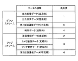
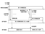
- the figure which shows the data transmitted / received between an operating device and information processing apparatus The figure which shows an example of the data contained in transmission information data
- the figure which shows an example of the data contained in communication management data The figure which shows an example of communication operation in case an operating device and an external device perform infrared communication
- generation method of each data contained in operation data The figure which shows an example of operation
- the flowchart which shows an example of the process in an operating device A flowchart showing an example of processing in the information processing apparatus
- FIG. 1 is an external view of an example of an information processing system.
- the information processing system 1 includes an operation device 2, an information processing device 3, and a display device 4.
- the information processing system 1 executes information processing in the information processing device 3 based on an operation on the operation device 2 and displays an image obtained by the information processing on the operation device 2 and / or the display device 4.
- the operating device 2 is portable and has a size that can be gripped by the user.
- the controller device 2 can wirelessly communicate with the information processing device 3.
- the controller device 2 includes an operation unit (in this embodiment, a button group 14, an acceleration sensor 23, a touch panel 12, and the like described later) that outputs data representing an operation by the user.
- the controller device 2 generates operation data based on an operation on the controller device 2 (operation unit), and transmits the operation data to the information processing device 3 wirelessly.
- the operation data is data representing an operation on the operation device 2 (operation unit), and the specific content may be anything.
- the details of the operation data in this embodiment will be described later (see “[6. Generation of operation data]” described later).
- the operation data represents a user instruction given to the controller device 2. That is, it can be said that the controller device 2 generates instruction data representing a user instruction and transmits the instruction data to the information processing apparatus 3 wirelessly. It can also be said that the operation data represents an input made to the controller device 2. That is, it can also be said that the controller device 2 generates input data representing an input made to the controller device 2 and transmits the input data to the information processing device 3 wirelessly.
- the controller device 2 includes a display unit.
- the controller device 2 receives the image data transmitted from the information processing device 3.
- the display unit displays an image represented by the received image data.
- This image data is typically generated based on information processing (first information processing described later) using the operation data in the information processing device 3.
- the controller device 2 has a function of controlling the display device 4.
- the operation device 2 can control the operation of the display device 4 by transmitting an infrared signal, which is a control signal, to the display device 4 (the dotted line shown in FIG. 1). See arrow).
- the controller device 2 may not have a function of controlling the display device 4.
- the information processing device 3 is, for example, a stationary information processing device.
- the information processing device 3 may be a game device capable of executing a game program, for example.
- the information processing device 3 performs information processing by executing a program stored in a storage medium (or storage device) accessible by the information processing device 3.
- the information processing device 3 receives the operation data transmitted from the operation device 2 and executes predetermined information processing using the operation data as an input.
- the information processing device 3 may receive operation data from devices other than the operation device 2 and execute the predetermined information processing based on the operation data received from each device.
- the information processing device 3 generates an image (image data) in the predetermined information processing. That is, the information processing apparatus 3 generates image data based on information processing using the operation data. This image is wirelessly transmitted from the information processing device 3 to the controller device 2 and displayed (output) on the controller device 2.
- output image an image generated in the predetermined information processing
- image data representing the image may be referred to as “output image data”.
- the information processing apparatus 3 may generate sound (sound data) in addition to images in the predetermined information processing. This sound is wirelessly transmitted from the information processing device 3 to the controller device 2 and is output from the controller device 2.
- sound generated in the predetermined information processing may be referred to as “output sound”
- sound data representing the sound may be referred to as “output sound data”.
- the information processing device 3 can communicate with the display device 4.
- the information processing device 3 and the display device 4 communicate with each other by wire.
- the communication between the information processing device 3 and the display device 4 may be wireless communication.
- the information processing device 3 may generate an image and / or sound to be output to the display device 4 in the predetermined information processing.
- the image to be output to the display device 4 may be the same as the image to be output to the controller device 2 (the output image) or may be different.
- the sound to be output to the display device 4 may be the same as or different from the sound to be output to the controller device 2 (the output sound described above).
- the display device 4 is, for example, a stationary display device.
- the display device 4 is a television receiver (television).
- the display device 4 typically has a larger screen than the display unit of the controller device 2.
- the display device 4 displays an image generated in information processing executed in the information processing device 3.
- the display device 4 has a speaker 5 (FIG. 4), and the speaker 5 outputs the sound generated in the information processing.
- the display device 4 has a function of receiving a control signal from the operation device 2.
- the display device 4 includes an infrared light receiver that can receive an infrared signal.
- the display device 4 performs an operation according to the infrared signal received by the infrared light receiving unit. That is, the display device 4 can receive an infrared signal that is a control signal and operate in accordance with the control signal.
- the information processing system 1 shows a configuration in which the information processing system 1 includes one operating device 2, but the information processing system 1 may have a configuration including two operating devices 2. That is, the information processing device 3 can communicate with the two controller devices 2. The information processing device 3 can receive operation data from each operation device 2. In addition, the information processing device 3 can transmit output image data (and output audio data) to each of the operation devices 2. Thus, in the present embodiment, the information processing device 3 can correspond to up to two controller devices 2. In the modification of the present embodiment, the information processing device 3 may be capable of wireless communication simultaneously with three or more operation devices 2.
- FIG. 2 is a front view of an example of the controller device 2.
- FIG. 3 is a rear view of an example of the controller device 2.
- the operating device 2 includes a housing 10 that is roughly a horizontally-long rectangular plate shape. It can also be said that the operation device 2 is a tablet-type information processing device (terminal device).
- the “plate shape” means a plate shape as a whole, and may have a curved surface in part or a protrusion or the like in part. Good.
- the shape of the operating device 2 (housing 10) may be any shape.
- the housing 10 is large enough to be gripped by the user. Accordingly, the user can move the controller device 2 and change the arrangement position of the controller device 2.
- the operating device 2 includes a display unit 11.
- the display unit 11 may be any display means, for example, an LCD (Liquid Crystal Display).
- the display unit 11 is provided near the center of the surface of the housing 10. Therefore, the user can hold the operating device 2 while looking at the screen of the display unit 11 by holding the housings 10 on both sides of the display unit 11. Note that the user can hold the operating device 2 sideways (with a long horizontal orientation) by holding the housings 10 on the left and right sides of the display unit 11, and hold the operating device 2 vertically. It can also be held (with a long vertical orientation).
- the operation device 2 includes the operation unit described above.
- the operation unit may be anything as long as it can output data representing an operation by the user.
- the controller device 2 includes a plurality of types of operation units described below. However, the controller device 2 only needs to include at least one operation unit, and the type of the operation unit may be arbitrary.
- the operation device 2 includes a touch panel 12 as an example of the operation unit described above.
- the touch panel 12 is provided on the screen of the display unit 11.
- the touch panel 12 may be a single touch method or a multi touch method.
- the housing 10 is provided with a storage hole for storing a touch pen used for operating the touch panel 12.
- the controller device 2 includes a direction input unit 13 as an example of the operation unit.
- the direction input unit 13 is an operation unit capable of inputting (instructing) a direction.
- the direction input unit 13 is an analog stick.
- the controller device 2 uses two analog sticks, ie, a left analog stick 13A provided on the left side of the display unit 11 and a left analog stick 13B provided on the right side of the display unit 11 as the direction input unit 13.
- the analog stick may be a direction input unit of a type in which a movable member (for example, a stick unit) can tilt in any direction (in other words, any angle in the up / down / left / right and diagonal directions) with respect to the surface of the housing 10.
- the movable member may be a type of direction input unit that can slide in any direction with respect to the surface of the housing 10.
- the analog stick is configured such that the movable member can be pressed in a direction substantially perpendicular to the surface of the housing 10. That is, the direction input unit 13 in this embodiment is an analog stick of a type that can perform an operation of moving the movable member in an arbitrary direction and an operation of pressing the movable member. Note that the movable member may not be configured to be depressible.
- the operation device 2 includes a button group 14 (each button 14A to 14I) as an example of an operation unit.
- Each button 14A to 14I is a key that can be pressed.
- a cross button (direction input button) 14A, a button 14B, a button 14C, and a button group 14E are provided on the surface of the housing 10.
- the buttons 14A to 14E provided on the surface of the housing 10 are arranged at positions where the user can operate with the thumb of the user while holding the left and right portions of the operating device 2. Therefore, the user can easily operate these buttons 14A to 14E even when moving with the operating device 2.
- the cross button 14 ⁇ / b> A has a cross shape, and can indicate at least the vertical and horizontal directions. Therefore, in the present embodiment, the cross button 14A may be used as the direction input unit.
- the button 14 ⁇ / b> C is a button for instructing to start a program executed in the controller device 2.
- this program may be referred to as a “second program” for the purpose of distinguishing it from a “first program” described later.
- the second program is a program executed by the controller device 2.
- information processing that is executed in the controller device 2 by the second program may be referred to as “second information processing”.
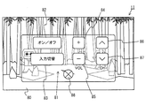
- the second program is a program for operating the display device (television) 4 in the present embodiment. Therefore, the controller device 2 has a function of a television remote control.
- the button 14C may be referred to as an “activation button”.
- the button 14B is a button for giving an instruction to display a predetermined menu screen.
- the button 14 ⁇ / b> D is a power button for turning on / off the power of the controller device 2. By operating the power button, the user can also remotely turn on / off the information processing apparatus 3.
- the first L button 14F and the first R button 14G are provided on both the left and right sides of the upper surface of the housing 10, respectively.
- the second L button 14 ⁇ / b> H and the second R button 14 ⁇ / b> I are provided on both the left and right sides of the back surface (back surface) of the housing 10.
- the second L button 14 ⁇ / b> H and the second R button 14 ⁇ / b> I are provided on the upper surface of the protrusion 19 formed on the back surface of the housing 10.
- each button 14A and 14E to 14I is appropriately assigned a function according to information processing executed by the information processing apparatus 3.
- a direction instruction or a selection instruction may be assigned to the cross button 14A and the button group 14E
- a determination instruction or a cancellation instruction may be assigned to each of the buttons 14E to 14I.
- the controller device 2 includes a button for instructing to turn on / off the screen display of the display unit 11 and / or a connection setting (pair) between the own device and the information processing device 3.
- buttons 14A to 14I shown in FIGS. 2 and 3 are merely examples, and the shape, number, and installation position of the buttons provided in the operation device 2 are arbitrary.
- a protrusion 19 is provided on the back side of the housing 10 (opposite the surface on which the display unit 11 is provided) (see FIG. 3).
- the protrusion 19 is a mountain-shaped member that protrudes from the back surface of the substantially plate-shaped housing 10.
- the protrusion 19 is formed so as to extend to the left and right, and can be said to have a bowl shape.
- the protrusion has a height (thickness) that can be hooked on a user's finger that holds the back surface of the housing 10.
- the user can hold the operation device 2 in a stable state without getting tired by holding his / her finger on the protrusion 19 (the protrusion 19 is placed on the finger) and holding it. 2 can be gripped.
- the protrusion 19 can be said to be a support member for supporting the housing 10 with a finger, and can also be called a finger hook.
- the shape and the arrangement position of the protrusion 19 are arbitrary.
- the controller device 2 may have a configuration in which the protrusion 19 is not provided.
- the controller device 2 includes a marker unit 15.
- the marker part 15 has the marker 15A and the marker 15B which are provided in the surface of the housing 10, as shown in FIG.
- Each marker 15A and marker 15B is formed of an infrared LED. This infrared LED is disposed inside a window that transmits infrared light.
- the marker unit 15 is used to calculate the position, posture, movement, or the like of a controller that can detect infrared light.
- the information processing apparatus 3 can control lighting of each infrared LED included in the marker unit 15.
- the operating device 2 includes a camera 16 that is an imaging device.
- the camera 16 includes an imaging device (for example, a CCD image sensor or a CMOS image sensor) having a predetermined resolution, and a lens. As shown in FIG. 2, in this embodiment, the camera 16 is provided on the surface of the housing 10. Therefore, the camera 16 can take an image of the face of the user who has the controller device 2, and can take an image of the user who is playing the game while looking at the screen of the display unit 11, for example.
- the operating device 2 includes a microphone 32 (see FIG. 4) that is an example of a voice input unit. As shown in FIG. 2, a microphone hole 18 is provided on the surface of the housing 10. The microphone 32 is provided inside the housing 10 behind the microphone hole 18. The microphone 32 detects sounds around the controller device 2 (for example, user's voice).
- the controller device 2 includes the camera 16 and the microphone 32. However, the controller device 2 may not include the camera 16 and the microphone 32, and may include only one of them. Also good.
- the operating device 2 includes a speaker 31 (see FIG. 4) which is an example of an audio output unit. As shown in FIG. 2, a speaker hole 17 is provided on the surface of the housing 10. The output sound of the speaker 31 is output from the speaker hole 17 to the outside of the controller device 2.
- the controller device 2 includes two speakers 31 and speaker holes 17 are provided at positions of the left speaker and the right speaker.
- the controller device 2 includes a knob (not shown) for adjusting the volume of the speaker 31.
- the controller device 2 includes an audio output terminal (not shown) for connecting an audio output unit such as an earphone. The position where the audio output terminal and the knob are provided may be anywhere. Note that the controller device 2 may be configured not to include an audio output unit.
- the housing 10 is provided with a window 20 capable of transmitting infrared rays.
- the window 20 is provided for transmitting and receiving an infrared signal in an infrared communication unit 36 and an infrared light emitting unit 38 to be described later. That is, in this embodiment, the infrared communication unit 36 and the infrared light emitting unit 38 are provided inside the window 20 (inside the housing 1).
- the infrared communication unit 36 receives an infrared signal from the outside of the controller device 2 through the window 20 and transmits the infrared signal to the outside of the controller device 2 through the window 20.
- the infrared light emitting unit 38 transmits an infrared signal to the outside of the controller device 2 through the window 20.
- the window 20 is located on the upper side of the housing 10 so that an infrared signal is emitted forward of the user (or an infrared signal is received from the front of the user) when both sides of the display unit 11 are gripped. Provided on the side (see FIG. 3). However, the window 20 may be provided at any position such as the back surface of the housing 10.
- the controller device 2 includes a connector 26 (see FIG. 3) for connecting peripheral devices to the controller device 2.
- the connector 26 is a communication terminal for transmitting / receiving data (information) to / from other peripheral devices connected to the controller device 2.
- the connector 26 may include a terminal for supplying power to the peripheral device and a terminal for charging.
- an “external device” another device that is different from the information processing device 3 and can communicate with the operation device 2 is referred to as an “external device”.
- the external device only needs to be able to communicate with the controller device 2, may be able to communicate with an infrared communication unit 36 described later, or may be able to communicate with the controller device 2 via the short-range wireless communication unit 37. Good.
- Any type of external device may be used, for example, an external storage medium such as a memory card, or an information processing terminal.
- communication between the controller device 2 and the external device may be referred to as “extended communication”.
- each component is merely examples.
- Each of the components may have other shapes, numbers, and installation positions.
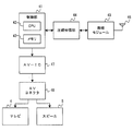
- FIG. 4 is a block diagram showing an internal configuration of the controller device 2 as an example.
- the controller device 2 includes the configuration shown in FIG. 4 in addition to the configurations shown in FIGS. 2 and 3.
- the electronic components of each component shown in FIG. 4 are mounted on, for example, an electronic circuit board and housed in the housing 10.
- the controller device 2 includes an input / output control unit 21.
- the input / output control unit 21 controls data input / output with respect to the operation unit connected to the input / output control unit 21.
- the input / output control unit 21 is connected to each operation unit (the touch panel 12 is connected via the touch panel controller 22). Hereinafter, each operation unit will be described.
- the operating device 2 includes a touch panel controller 22.
- the touch panel controller 22 is a circuit that controls the touch panel 12.
- the touch panel controller 22 is connected to the touch panel 12 and is connected to the input / output control unit 21.
- the touch panel controller 22 generates input position data based on a signal from the touch panel 12 and outputs the input position data to the input / output control unit 21.
- the input position data represents a position where an input is performed on the input surface of the touch panel 12 (referred to as “input position”, also referred to as touch position). More specifically, the input position data may be data representing two-dimensional coordinates indicating the input position.
- the touch panel controller 22 reads a signal from the touch panel 12 and generates input position data at a rate of once per predetermined time.
- Various control instructions for the touch panel 12 are output from the input / output control unit 21 to the touch panel controller 22.
- the above-described direction input unit 13 is connected to the input / output control unit 21.
- the direction input unit 13 outputs instruction direction data indicating the direction instructed by the user to the input / output control unit 21.
- the instruction direction data represents the moving direction and moving amount of the movable member operated by the user's finger.
- the indication direction data represents, for example, the direction and amount in which the movable member is tilted (or slid). Specifically, the amount of inclination in the biaxial direction in the vertical direction and the horizontal direction is detected and output, respectively.
- the values of these two-axis components can also be regarded as a two-dimensional vector representing the direction and quantity.
- the indication direction data further indicates whether or not the movable member has been pressed.
- the above-described button group 14 (the buttons 14A to 14I) is connected to the input / output control unit 21.
- the button group 14 outputs button data representing the input status of the buttons 14A to 14I to the input / output control unit 21.
- the button data represents, for example, for each button whether or not each button 14A to 14I has been pressed.
- some buttons for example, the first L button 14F and the first R button 14G
- the button data represents the push-in amount in addition to whether or not the button capable of detecting the push-in amount is pressed.
- the operating device 2 includes an acceleration sensor 23 as an example of an operating unit.
- the acceleration sensor 23 is connected to the input / output control unit 21.
- the acceleration sensor 23 is provided inside the housing 10 and detects the magnitude of linear acceleration along one or more predetermined axial directions. Specifically, the acceleration sensor 23 has a linear acceleration of each axis, where the long side direction of the housing 10 is the x axis, the short side direction of the housing 10 is the y axis, and the direction perpendicular to the surface of the housing 10 is the y axis. Detect the size of. Acceleration data representing the detected acceleration is output to the input / output control unit 21.
- a control instruction for the acceleration sensor 23 is output from the input / output control unit 21 to the acceleration sensor 23.
- the acceleration sensor 23 is, for example, a capacitance type MEMS acceleration sensor, but may be another type of acceleration sensor. In the above description, the acceleration sensor 23 has been described as detecting acceleration in the triaxial direction. However, the acceleration sensor 23 may be biaxial, or any sensor that detects acceleration of one axis or more.
- the operating device 2 includes a gyro sensor 24 as an example of an operation unit.
- the gyro sensor 24 is connected to the input / output control unit 21.
- the gyro sensor 24 is provided inside the housing 10 and detects an angular velocity around one or more predetermined axes.
- the detection axis of the gyro sensor 24 is the same as the detection axis of the acceleration sensor 23, and is the x axis, the y axis, and the z axis.
- Angular velocity data representing the detected angular velocity is output to the input / output control unit 21.
- a control instruction for the gyro sensor 24 is output from the input / output control unit 21 to the gyro sensor 24.
- the gyro sensor 24 has been described as detecting angular velocities about three axes. However, the gyro sensor 24 may be two axes, or any sensor that detects angular velocities of one or more axes.
- the operating device 2 includes a magnetic sensor 25 as an example of an operating unit.
- the magnetic sensor 25 is connected to the input / output control unit 21.
- the magnetic sensor 25 detects the magnetic direction (azimuth) by detecting the magnitude and direction of the magnetic field. Magnetic data indicating the detected magnetic direction is output to the input / output control unit 21.
- a control instruction for the magnetic sensor 25 is output from the input / output control unit 21 to the magnetic sensor 25.
- an MI magnetic impedance
- a fluxgate sensor a Hall element
- GMR giant magnetoresistance
- TMR tunnelnel magnetoresistance
- AMR anisotropic magnetoresistance
- the magnetic sensor 25 is not limited to one that detects a azimuth in a strict sense, and may be any sensor that can detect a direction based on magnetism.
- the magnetic sensor 25 is described as detecting a magnetic direction with a three-dimensional value here, but any sensor may be used as long as it detects a one-dimensional or higher magnetic direction.
- the controller device 2 includes the acceleration sensor 23, the gyro sensor 24, and the magnetic sensor 25 as sensors for detecting at least one of the position, posture, and movement of the controller device 2.
- the controller device 2 may be configured to include only one or two of these sensors. Further, the controller device 2 may be configured to include other sensors instead of these sensors or together with these sensors.
- the input / output control unit 21 receives each data output from each operation unit and generates operation data including the data. That is, the input / output control unit 21 is a generation unit that generates operation data based on an operation on the controller device 2.
- the input / output control unit 21 is connected to the communication data management unit 27.
- the input / output control unit 21 outputs the generated operation data to the communication data management unit 27.
- the input / output control unit 21 generates and outputs operation data at a frequency of once every predetermined time (time T4 to be described later).
- the connector 26 described above is connected to the input / output control unit 21.
- the input / output control unit 21 receives data representing an operation on the other device and outputs the data to the communication data management unit 27. Good.
- the controller device 2 includes a power supply IC 38.
- the power supply IC 38 is connected to the input / output control unit 21.
- the power supply IC 38 controls power supply from the built-in battery to each unit in the controller device 2.
- a charger or a cable that can acquire power from an external power supply can be connected to the power supply IC 38 via a charging connector.
- the operating device 2 can supply and charge power from an external power source using the charger or cable.
- the controller device 2 can be charged by attaching the controller device 2 to a cradle having a charging function (not shown).
- the controller device 2 includes a communication data management unit 27.
- the communication data management unit 27 executes various processes related to communication with the information processing apparatus 3.
- the communication data management unit 27 includes a CPU 28 and a memory 29.
- the communication data management unit 27 is, for example, an LSI (also referred to as a codec LSI) that can execute data compression / decompression processing described later.
- the controller device 2 includes a flash memory 35, and the flash memory 35 is connected to the communication data management unit 27.
- the flash memory 35 stores various programs executed in the controller device 2.
- a program for management and / or communication of the own device (operation device 2), the above-described second program, and the like are stored in the flash memory 35.
- the CPU 28 executes the various processes described above by executing programs stored in the flash memory 35.
- the memory 29 is used as a storage area when the above-described various processes are executed.
- a partial area of the memory 29 may be used as a memory (so-called VRAM) for an image displayed on the display unit 11.
- the communication data management unit 27 performs various processes on data to be transmitted to the information processing device 3. That is, the communication data management unit 27 receives data from the components connected to the communication data management unit 27, performs predetermined processing (for example, compression processing described later) as necessary, and transmits the data to the information processing device 3. Generate data.
- the communication data management unit 27 performs various processes on the data received from the information processing device 3. That is, the communication data management unit 27 performs predetermined processing (for example, expansion processing described later) on the data received from the information processing device 3 as necessary, and is connected to the communication data management unit 27. Output processed data to. Details of processing executed by the communication data management unit 27 will be described later. Hereinafter, each component connected to the communication data management unit 27 will be described.
- the display unit 11 described above is connected to the communication data management unit 27.
- the display unit 11 receives the output image data transmitted from the information processing device 3 from the communication data management unit 27 and displays an image represented by the output image data. Since the information processing device 3 transmits the output image data with a predetermined frequency and the communication data management unit 27 outputs the output image data with a predetermined frequency, the display unit 11 can display a moving image.
- the camera 16 described above is connected to the communication data management unit 27.
- the camera 16 captures an image and outputs the captured image data to the communication data management unit 27.
- data of an image captured by the camera 16 is referred to as “camera image data”.
- the communication data management unit 27 outputs a control instruction for the camera 16 such as an image capturing instruction to the camera 16.
- the camera 16 can also capture moving images. That is, the camera 16 can repeatedly capture images and repeatedly output camera image data to the communication data management unit 27.
- the controller device 2 includes a sound IC 30.
- the sound IC 30 is connected to the communication data management unit 27.
- the sound IC 30 is connected to the speaker 31 and the microphone 32.
- the sound IC 30 controls input / output of audio data with respect to the speaker 31 and the microphone 32. That is, when audio data (output audio data) is received from the communication data management unit 27, the sound IC 30 outputs an audio signal obtained by performing D / A conversion on the audio data to the speaker 31. As a result, sound is generated from the speaker 31.
- the microphone 32 detects a sound (such as a user's voice) transmitted to the controller device 2 and outputs an audio signal indicating the detected sound to the sound IC 30.
- the sound IC 30 outputs audio data (microphone audio data) obtained by performing A / D conversion on the audio signal from the microphone 32 to the communication data management unit 27.
- the controller device 2 includes a wireless module 33 and an antenna 34.
- the wireless module 33 is connected to the communication data management unit 27.
- An antenna 34 is connected to the wireless module 33.
- the wireless module 33 performs wireless communication with the information processing apparatus 3 using the antenna 34.
- the wireless module 33 is a communication module that has received Wi-Fi authentication, for example.
- the wireless module 33 may perform high-speed wireless communication with the information processing apparatus 3 using, for example, MIMO (Multiple Input Multiple Output) technology adopted in the IEEE 802.11n standard, or other communication. Wireless communication with the information processing apparatus 3 may be performed using a method.
- MIMO Multiple Input Multiple Output
- the communication data management unit 27 When data is transmitted from the controller device 2 to the information processing device 3, the communication data management unit 27 outputs data to be transmitted to the information processing device 3 to the wireless module 33.
- the wireless module 33 wirelessly transmits data to be transmitted to the information processing apparatus 3 via the antenna 34.
- the wireless module 33 receives the data from the information processing device 3 using the antenna 34, and the received data is transmitted to the communication data management unit 27. Output to.
- the communication data management unit 27 outputs the received data to an appropriate component to which the data is to be sent.
- the data is compressed by the transmitting device and transmitted and received by the receiving device. Data may be decompressed.
- the communication data management unit 27 executes the above compression processing and the expansion processing for the compression processing performed in the information processing apparatus 3.
- data that is compressed and transmitted in communication between the controller device 2 and the information processing device 3 is arbitrary.
- data subjected to compression processing on the transmission side includes output image data and output audio data transmitted from the information processing device 3, and camera image data and microphone transmitted from the operation device 2. Audio data.
- only output image data from the information processing device 3 may be compressed, or output image data from the information processing device 3 and camera image data from the operation device 2 are compressed. May be.
- data other than the above may be compressed, or all data may be transmitted without compression.
- any compression and decompression method performed in the controller device 2 and the information processing device 3 may be used.
- each device is, for example, H.264.
- Data is compressed using a highly efficient compression technique such as the H.264 standard. Therefore, according to the present embodiment, the image and / or sound generated on the transmission side can be transmitted to the reception side at high speed, and the delay generated on the reception side can be reduced.
- the controller device 2 includes an infrared communication unit 36.
- the infrared communication unit 36 performs infrared communication with an external device other than the information processing device 3.
- the infrared communication unit 36 has a function of performing infrared communication in accordance with, for example, the IrDA standard.
- the infrared communication unit 36 is connected to the communication data management unit 27.
- the communication data management unit 27 When data is transmitted from the controller device 2 to the external device by infrared communication, the communication data management unit 27 outputs data to be transmitted to the external device to the infrared communication unit 36.
- the infrared communication unit 36 outputs an infrared signal representing data to be transmitted.
- the infrared communication unit 36 receives the infrared signal from the external device and outputs the received infrared signal data to the communication data management unit 27.
- the communication data management unit 27 controls infrared communication using the infrared communication unit 36 (see “ ⁇ 5-4: Operation when Communication with External Device>”).
- the controller device 2 also includes a short-range wireless communication unit 37.
- the short-range wireless communication unit 37 performs communication (non-contact communication) according to the NFC (Near Field Communication) standard with an external device other than the information processing device 3.
- the near field communication unit 37 is connected to the communication data management unit 27.
- the communication data management unit 27 When data is transmitted from the controller device 2 to the external device by short-range wireless communication, the communication data management unit 27 outputs data to be transmitted to the external device to the short-range wireless communication unit 37.
- the short-range wireless communication unit 37 outputs a wireless signal representing data to be transmitted.
- the short-range wireless communication unit 37 receives a wireless signal from the external device and outputs the received wireless signal data to the communication data management unit 27.
- the communication data management unit 27 controls communication using the short-range wireless communication unit 37 (see “ ⁇ 5-4: Operation when Communication with External Device>”).
- data may be transmitted from the external device to the information processing device 3 via the operation device 2.
- data may be transmitted from the information processing device 3 to the external device via the controller device 2.
- the controller device 2 is an example of an extended communication unit that performs communication (extended communication) with another external device different from the information processing device 3.
- a distance wireless communication unit 37 is provided.
- the extended communication unit included in the controller device 2 may be any device as long as it has a function of communicating with the external device.
- the controller device 2 may include only one of the above-described components (the infrared communication unit 36 and the short-range wireless communication unit 37), or may include a communication unit that is different from the component. May be.
- the controller device 2 includes an infrared light emitting unit 38.
- the infrared light emitting unit 38 outputs an infrared signal for controlling the display device 4.
- the infrared light emission part 38 has infrared LED, for example.
- the communication data management unit 27 controls the output of infrared signals (infrared emission) by the infrared light emitting unit 38.
- a control signal infrared signal
- the communication data management unit 27 outputs a control signal to be transmitted to the display device 4 to the infrared light emitting unit 38.
- the infrared light emitting unit 38 outputs an infrared signal representing a control signal received from the communication data management unit 27.
- the marker unit 15 described above is connected to the communication data management unit 27. Light emission of the infrared LED included in the marker unit 15 is controlled by a control instruction from the communication data management unit 27.
- the control for the marker unit 15 may be simply ON / OFF of power supply.
- the operating device 2 includes a vibrator 39.
- the vibrator 39 is connected to the communication data management unit 27.
- the vibrator 39 is an arbitrary member that can vibrate, for example, a vibration motor or a solenoid.
- the vibration of the vibrator 39 is controlled by the communication data management unit 27.
- vibration is generated in the controller device 2, and as a result, the vibration is transmitted to the user's hand holding the controller device 2.
- the vibrator 39 can be used, for example, in a so-called vibration-compatible game.
- FIG. 5 is a block diagram illustrating an internal configuration of the information processing apparatus 3 as an example.
- the information processing apparatus 3 includes the units illustrated in FIG.
- the information processing apparatus 3 includes a control unit 41.
- the control unit 41 includes a CPU 42 and a memory 43.
- the control unit 41 is mounted in the information processing apparatus 3 as a system LSI, for example.
- the control unit 41 includes a processor (GPU) for generating an image, a memory (VRAM) for storing the generated image, and / or data for the control unit 41.
- a member such as a circuit for controlling input / output may be included.
- the control unit 41 generates output image data by executing predetermined information processing.
- the predetermined information processing executed by the control unit 41 may be referred to as “first information processing”.
- the information processing apparatus 3 includes a program storage unit (not shown) that stores a program.
- the CPU 42 executes a program stored in the program storage unit.
- the first information processing is executed in the information processing device 3.
- a program for executing the first information processing may be referred to as a “first program”.
- the first information processing is a process of generating output image data and / or output audio data using operation data as input.
- the specific content of the first information processing may be anything.
- the first information processing may be, for example, a game process that controls a game object based on operation data, or a browser process that displays a Web page based on operation data. That is, the first program may be, for example, a game program for executing game processing, or a browser program for executing browser processing.
- the output image generated when the control unit 41 executes the first information processing is displayed on the controller device 2.
- an image generated by the control unit 41 is displayed on the display device 4.
- the output sound generated by the control unit 41 is output by the controller device 2.
- the sound generated in the control unit 41 is output from the speaker 5.
- the information processing apparatus 3 includes a compression / decompression unit 44.
- the compression / decompression unit 44 is, for example, an LSI (also referred to as a codec LSI) capable of executing data compression / decompression processing.
- the compression / decompression unit 44 is connected to the control unit 41. Note that the connection between the control unit 41 and the compression / decompression unit 44 may be performed in accordance with, for example, the USB (Universal Serial Bus) standard.
- the compression / decompression method by the compression / decompression unit 44 is the same as the compression / decompression method by the communication data management unit 27 in the controller device 2.
- the information processing apparatus 3 includes a wireless module 45 and an antenna 46.
- the wireless module 45 is connected to the compression / decompression unit 44.
- An antenna 46 is connected to the wireless module 45.
- the wireless module 45 performs wireless communication with the information processing apparatus 3 using the antenna 46.
- the wireless module 45 can wirelessly communicate with the wireless module 33 of the controller device 2.
- the wireless module 45 has the same function as the wireless module 33 of the controller device 2.
- the control unit 41 When data is transmitted from the information processing device 3 to the controller device 2, the control unit 41 outputs data to be transmitted to the compression / decompression unit 44.
- the compression / decompression unit 44 compresses data to be transmitted to the controller device 2 as necessary, and outputs the compressed data to the wireless module 45.
- the compression / decompression unit 44 compresses the output image data and output audio data generated by the control unit 41, and outputs the compressed data to the wireless module 45. Further, the compression / decompression unit 44 outputs the data not compressed among the data sent from the control unit 41 to the wireless module 45 as it is.
- the wireless module 45 wirelessly transmits the data output from the compression / decompression unit 44 to the controller device 2 via the antenna 46.
- the wireless module 45 receives the data from the controller device 2 using the antenna 46 and outputs the received data to the compression / decompression unit 44.
- the compression / decompression unit 44 decompresses the compressed data when the compressed data is received from the controller device 2.
- the compression / decompression unit 44 decompresses, for example, camera image data and microphone audio data that are compressed and transmitted by the controller device 2.
- the compression / decompression unit 44 outputs the decompressed data to the control unit 41. If the data received from the controller device 2 is not compressed, the compression / decompression unit 44 outputs the data to the control unit 41 as it is.
- the information processing apparatus 3 includes an AV-IC (Integrated Circuit) 47 and an AV connector 48.
- AV-IC 47 Integrated Circuit
- the AV-IC 47 outputs the read image data to the display device 4 via the AV connector 48.
- the AV-IC 47 outputs the read audio data to the speaker 5 built in the display device 4.
- an image is displayed on the display device 4, and sound is output from the speaker 5.
- the connection and communication between the information processing device 3 and the display device 4 may be performed by any method.
- the information processing device 3 may transmit a control signal for controlling the display device 4 to the display device 4 in a wired or wireless manner.
- a control signal for controlling the display device 4 for example, an HDMI cable conforming to the HDMI (High-Definition Multimedia Interface) standard may be used.
- HDMI High-Definition Multimedia Interface
- CEC Consumer Electronics Control
- the information processing apparatus 3 may have, for example, the following functions in addition to the above functions. That is, the information processing apparatus 3 can be connected to a communication network (for example, the Internet) outside the information processing system 1 and communicates with other information processing apparatuses outside the information processing system 1 via the communication network. You may have the function to perform. Further, the information processing device 3 may have a function of performing wired or wireless communication with an input device different from the operation device 2. Further, the information processing apparatus 3 includes an expansion connector and may have a function of connecting an expansion device (for example, an external storage medium and a peripheral device) via the expansion connector.
- a communication network for example, the Internet
- the information processing device 3 may have a function of performing wired or wireless communication with an input device different from the operation device 2.
- the information processing apparatus 3 includes an expansion connector and may have a function of connecting an expansion device (for example, an external storage medium and a peripheral device) via the expansion connector.
- FIG. 6 is a diagram illustrating data transmitted and received between the controller device 2 and the information processing device 3.
- the information processing device 3 transmits the output image data described above to the controller device 2.
- the controller device 2 receives the output image data. Thereby, the output image generated by the information processing device 3 can be displayed on the controller device 2.
- the information processing device 3 compresses the output image data and transmits it to the controller device 2.
- the controller device 2 receives the compressed output image data.
- the communication data management unit 27 of the controller device 2 expands the received compressed output image data.
- the communication data management unit 27 outputs the decompressed output image data to the display unit 11. As a result, the output image is displayed on the display unit 11.
- the information processing device 3 transmits the above-described output audio data to the operation device 2.
- the controller device 2 receives the output audio data.
- the output sound generated by the information processing device 3 can be output from the controller device 2.
- the information processing device 3 compresses the output audio data and transmits it to the controller device 2.
- the controller device 2 receives the compressed output audio data.
- the communication data management unit 27 of the controller device 2 expands the received compressed output audio data.
- the communication data management unit 27 outputs the decompressed output audio data to the sound IC 30. As a result, output sound is output from the speaker 31.
- the information processing device 3 transmits the first extended communication data to the controller device 2.
- the first extended communication data is data transmitted from the information processing device 3 to the controller device 2 when the controller device 2 communicates with the external device described above.
- the information processing device 3 transmits, for example, data representing a command (command) to the controller device 2 or the external device, data to be transmitted to the external device, and the like to the controller device 2 as first extended communication data.
- the controller device 2 (wireless module 33) receives the first extended communication data transmitted from the information processing device 3.
- the communication data management unit 27 executes processing according to a command represented by the received first extended communication data, or transmits the received first extended communication data to an external device. In this way, the information processing device 3 can communicate with the external device via the controller device 2 using the first extended communication data.
- An example of the communication operation related to the first extended communication data will be described later (see “ ⁇ 5-4: Operation when Communication with External Device>” described later).
- the information processing device 3 transmits control data to the controller device 2.
- the control data is data used for control related to communication between the controller device 2 and the information processing device 3, for example.
- the specific content of the control data may be anything.
- the control data may represent content related to wireless communication settings.
- the controller device 2 transmits the transmission information data to the information processing device 3.
- the transmission information data is data representing information to be transmitted to the information processing device 3.
- FIG. 7 is a diagram illustrating an example of data included in the transmission information data.
- the transmission information data 50 includes the operation data 51 described above, for example. Since the operation information 51 is included in the transmission information data 50, the information processing device 3 can recognize the content of the operation on the operation device 2. Details of the operation data 51 will be described later (see “[6. Generation of operation data]” described later).
- the transmission information data 50 includes management data 52.
- the management data 52 represents a state related to the controller device 2. By including the management data 52 in the transmission information data 50, the information processing device 3 can recognize the state of the controller device 2.
- the management data 52 is information to be managed in the information processing apparatus 3.
- the management data 52 includes communication management data 53.
- the communication management data 53 represents a state relating to communication between the controller device 2 and the external device described above.
- the management data 52 includes activation state data 54.
- the activation state data 54 represents the activation state of the second program. Details of the communication management data 53 and the activation state data 54 will be described later.
- the management data 52 may be data representing the state of the controller device 2, data representing a state related to communication between the controller device 2 and an external device, or the controller device 2. It may represent the state of an external device that can communicate.
- the specific contents of the management data 52 may be anything.
- the management data 52 may be configured not to include one or both of the communication management data 53 and the activation state data 54.
- the management data 52 may include data other than the communication management data 53 and the activation state data 54.
- the transmission information data 50 is generated in the controller device 2 by the following method, for example.
- the operation data 51 is generated by the input / output control unit 21 and output to the communication data management unit 27.
- the communication data management unit 27 adds management data 52 to the operation data 51. That is, the communication data management unit 27 generates transmission information data 50 including the operation data 51 and the management data 52.
- the communication data management unit 27 outputs the transmission information data 50 to the wireless module 33. As a result, the transmission information data 50 is transmitted to the information processing apparatus 3.
- the communication data management unit 27 generates and outputs the transmission information data 50 at a frequency of once every predetermined time (time T4 (see FIG. 8) described later).
- the transmission information data 50 is transmitted from the controller device 2 to the information processing device 3. That is, the controller device 2 transmits the management data 52 together with the operation data 51 to the information processing device 3. In other words, the controller device 2 transmits the operation data 51 and the management data 52 at the same frequency. More specifically, the controller device 2 transmits the operation data 51 and the management data 52 at the same timing. In the modification of the present embodiment, the controller device 2 may transmit the operation data 51 and the management data 52 separately (at different timings) or may not transmit the management data 52. .
- the controller device 2 may include other data than the above in the transmission information data 50 and transmit it to the information processing device 3.
- the transmission information data 50 may include data acquired from the peripheral device (for example, data representing an operation on the peripheral device).
- the input / output control unit 21 receives data from the peripheral device via the connector 26 and outputs the data to the communication data management unit 27.
- the communication data management unit 27 generates transmission information data 50 including data acquired from the peripheral device.
- the transmission information data 50 may include data related to an audio output unit (earphone or the like) connected to the above-described audio output terminal.
- the transmission information data 50 may include data indicating whether the voice output unit has a voice input function (for example, whether the earphone has a microphone function). Further, for example, the transmission information data 50 may include data indicating whether or not the voice output unit has a button, or include data indicating the input status (whether or not the button is pressed) of the button. Also good. These data may be included in the transmission information data 50 as the management data 52.
- the controller device 2 transmits the above-described camera image data to the information processing device 3.
- the controller device 2 compresses the camera image data and transmits it to the information processing device 3.
- the communication data management unit 27 compresses the camera image data received from the camera 16.
- the communication data management unit 27 outputs the compressed camera image data to the wireless module 33.
- the compressed camera image data is transmitted to the information processing device 3 by the wireless module 33.
- the information processing apparatus 3 can receive the camera image data and can execute information processing using the camera image data.
- the controller device 2 transmits the above microphone sound data to the information processing device 3.
- the controller device 2 compresses the microphone sound data and transmits it to the information processing device 3.
- the communication data management unit 27 compresses microphone audio data received from the microphone 32 via the sound IC 30.
- the communication data management unit 27 outputs the compressed microphone sound data to the wireless module 33.
- the compressed microphone sound data is transmitted to the information processing device 3 by the wireless module 33.
- the information processing apparatus 3 can receive microphone sound data and can execute information processing using the microphone sound data.
- the controller device 2 transmits the second extended communication data to the information processing device 3.
- the second extended communication data is data transmitted from the controller device 2 to the information processing device 3 when the controller device 2 communicates with the external device described above.
- the controller device 2 receives data to be transmitted to the information processor 3 from the external device.
- the communication data management unit 27 transmits, for example, data received from an external device to the information processing device 3 as second extended communication data.
- the information processing device 3 can acquire data transmitted from the external device via the controller device 2 by using the second extended communication data.
- An example of communication operation related to the second extended communication data will be described later (see “ ⁇ 5-4: Operation when Communication with External Device>” described later).
- extended communication data (first extended communication data and second extended communication data) is transmitted irregularly. That is, when the extended communication data to be transmitted is generated in the own device, the information processing device 3 and the controller device 2 transmit the extended communication data to the partner side. Accordingly, when there is no information to be transmitted as the extended communication data, communication can be efficiently performed without transmitting unnecessary data between the controller device 2 and the information processing device 3.
- data other than the extended communication data among the data shown in FIG. 6 can be transmitted periodically (in other words, repeatedly at a rate of once per predetermined time). As a result, the other data can be periodically acquired on the receiving side without interruption of communication. Note that the other data need not always be transmitted regularly.
- the controller device 2 transmits a part of the other data (for example, camera image data and microphone sound data). And a mode in which no transmission is performed.
- each data shown in FIG. 6 is transmitted and received between the controller device 2 and the information processing device 3.
- the information processing apparatus 3 may operate in a mode that does not transmit output audio data, or may not have a function of transmitting output audio data.
- the controller device 2 may operate in a mode in which camera image data and / or microphone sound data is not transmitted, or may not have a function of transmitting camera image data and / or microphone sound data ( At this time, the controller device 2 may not include the camera 16 and / or the microphone 32).
- the extended communication data is transmitted / received only when the controller device 2 and the external device communicate with each other, and when the controller device 2 and the external device do not communicate (there is an external device that can communicate with the controller device 2). If not, it may not be transmitted / received. Further, the controller device 2 may not have a function of communicating with an external device, and may not have a function of transmitting and receiving each extended communication data.
- communication priority is set for each data transmitted and received between the controller device 2 and the information processing device 3.
- This priority represents a priority order to be transmitted first when the controller device 2 and the information processing device 3 (respective wireless modules 33 and 45) can transmit a plurality of data.
- the priority represents the order of data transmitted with priority in the above case.
- such a priority can be set for a communication module that has received Wi-Fi authentication.
- the priority is set as follows for each data.
- Priority 1 Output image data and output audio data priority 2: Transmission information data priority 3: Camera image data and microphone audio data priority 4: Control data priority 5: First extended communication data priority 6: Second Extended communication data
- output image data and output audio data are transmitted with the highest priority. Transmission information data is transmitted with priority over other data other than output image data and output audio data. Thus, output image data, output audio data, and transmission information data are transmitted with priority over other data.
- each extended communication data has a lower priority than other data. According to this, even when communication is performed between the controller device 2 and the external device, transmission of other data is not delayed for transmission of each extended communication data. Can be transmitted stably.
- priority setting shown in FIG. 6 is an example, and the priority set for each of the data is arbitrary. Further, priority may not be set for each of the data (same priority is set).
- the information processing system 1 can support up to two operation devices 2. That is, the information processing system 1 includes a first communication mode in which the information processing device and one operating device 2 communicate with each other, and a second communication mode in which the information processing device and the two operating devices 2 communicate with each other. It can operate in both modes.
- FIG. 8 is a diagram illustrating a transmission timing of each data transmitted / received between the controller device 2 and the information processing device 3 in the first communication mode.
- one rectangular block represents one unit (one packet) of data transmission (the same applies to FIG. 9).
- the information processing device 3 transmits a synchronization signal to the controller device 2.
- the synchronization signal is a signal for synchronizing several processes in the information processing device 3 and the controller device 2. That is, the processing timing in the information processing device 3 and the controller device 2 can be aligned by the synchronization signal.
- the information processing device 3 transmits a synchronization signal at an interval of a predetermined time T1.
- the controller device 2 receives the synchronization signal at the interval of the time T1.
- the output image data is transmitted in synchronization with the synchronization signal, and the update interval of the image represented by the output image data is the time T1. That is, it can be said that the time T1 is one frame time.
- the time T1 is set to 16.68 [msec], for example.
- the transmission frequency of the synchronization signal that is, the update frequency (frame rate) of the image represented by the output image data is about 59.94 [fps] (generally called 60 [fps]). Become.
- the information processing device 3 transmits output image data to the controller device 2.
- the information processing device 3 transmits output image data for one image (one screen) at a predetermined frequency. That is, the information processing device 3 transmits output image data for one image during the one frame time.
- the controller device 2 receives output image data for one image at the predetermined frequency.
- the display unit 11 updates and displays the image at a rate of once per frame time.
- the information processing apparatus 3 divides the output image data into a plurality of (20 pieces in the figure) packets and transmits them. In the present embodiment, any method of compressing and transmitting output image data may be used.
- the compression / decompression unit 44 may divide an image for one image into a plurality of regions and perform compression processing for each of the divided regions.
- the wireless module 45 divides the compressed data in the area into a plurality of packets and transmits them. Each packet is transmitted at a predetermined time interval (for example, 569 [ ⁇ sec]).
- the information processing device 3 changes the number of divisions according to the communication status and / or according to the data amount transmitted / received between the controller device 2 and the information processing device 3. May be. For example, a first mode in which some data among various data that can be transmitted between the controller device 2 and the information processing device 3 is not transmitted (for example, a mode in which the controller device 2 does not transmit microphone audio data and camera image data). ) And the second mode in which all the various data are transmitted, the information processing system 1 is operable. In this case, the number of divisions may be set relatively large in the first mode, and the number of divisions may be set relatively small in the second mode.
- output image data is transmitted in synchronization with the synchronization signal.
- the information processing device 3 transmits the output image data at a timing determined by the synchronization signal. Specifically, the information processing device 3 transmits the output image data (the first packet of the output image data) after the elapse of a predetermined time T2 after the synchronization signal is transmitted.
- the time T2 is set to 3401 [ ⁇ sec], for example.
- the information processing device 3 transmits output sound data to the controller device 2.
- the output audio data is transmitted asynchronously with the synchronization signal (in other words, output image data).
- the information processing device 3 transmits the output audio data at a timing independent of the synchronization signal.
- the controller device 2 receives the output audio data from the information processing device 3 at a timing independent of the synchronization signal.
- the information processing device 3 transmits one packet of output audio data at an interval of a predetermined time T3.
- the time T3 is set to 8.83 [msec], for example. At this time, one packet of output audio data is transmitted twice or once per frame time.
- the controller device 2 transmits the transmission information data to the information processing device 3.
- the controller device 2 transmits transmission information data at a predetermined frequency. That is, the controller device 2 transmits the transmission information data at an interval of the predetermined time T4.
- the information processing device 3 receives the transmission information data from the controller device 2 at the predetermined frequency.
- the transmission information data is transmitted at a frequency m times the transmission frequency of output image data for one image.
- the transmission information data is transmitted in synchronization with the synchronization signal. That is, the controller device 2 transmits the transmission information data at a timing determined by the synchronization signal. Specifically, the controller device 2 starts processing for transmitting transmission information data when a predetermined time T5 has elapsed since the synchronization signal was transmitted.
- the time T5 is set to 16 [msec], for example.
- the controller device 2 may set the time when the synchronization signal is received as the “time when the synchronization signal is transmitted”. Further, the controller device 2 may transmit the transmission information data after a predetermined time has elapsed from the time when the synchronization signal is received.
- the controller device 2 performs a predetermined operation in the controller device 2 at a timing determined by the synchronization signal. For example, the controller device 2 starts an image display (drawing) process of output image data when a predetermined time T5 has elapsed since the synchronization signal was transmitted.
- the time T5 is set to 16 [msec], for example.
- the drawing process is started before reception of all output image data.
- the controller device 2 receives the image of the received and decoded area. It is possible to perform drawing processing from. The reception and decoding of all output image data is completed at the latest before the last area is drawn.
- the drawing process is performed by the timing at which the drawing process is started in the frame period following the frame period in which the drawing process is started (the period from when the first synchronization signal is sent to when the first synchronization signal is sent next). Complete. Therefore, the time required from the transmission of the synchronization signal until the output image is displayed on the controller device 2 is within T1 + T5, which is shorter than the time for two frames. Therefore, in the present embodiment, although the image is transmitted from the information processing device 3 to the controller device 2 wirelessly, it is possible to perform very high-speed drawing in the controller device.
- the controller device 2 transmits the camera image data to the information processing device 3.
- the controller device 2 transmits camera image data for one image at a predetermined frequency.
- the information processing device 3 receives camera image data for one image from the controller device 2 at the predetermined frequency. For example, as illustrated in FIG. 8, the controller device 2 transmits camera image data for one image during two frame times (one rate every two frame times). That is, the transmission frequency of camera image data for one image is 1 ⁇ 2 of the transmission frequency of output image data for one image.
- the communication data management unit 27 may perform compression processing on camera image data for one image. Further, the wireless module 33 may divide the compressed camera image data into a plurality of packets (15 in FIG. 8) and transmit the packets. Note that the controller device 2 (for example, the communication data management unit 27) compresses the compression rate (in other words, depending on the communication status and / or the amount of data transmitted / received between the controller device 2 and the information processing device 3). For example, the number of packets) may be changed. For example, the compression rate may be set relatively low in the first mode, and the compression rate may be set relatively high in the second mode.
- the camera image data is transmitted in synchronization with a synchronization signal (in other words, transmission information data). That is, the controller device 2 transmits the camera image data at a timing determined by the synchronization signal. In the present embodiment, the controller device 2 transmits the last packet of the camera image data for one image in synchronization with the synchronization signal, and can transmit other packets other than the last packet. As soon as it is (ie, as soon as compression is complete). Specifically, the controller device 2 transmits the last packet when a predetermined time T6 has elapsed since the synchronization signal was transmitted. In the present embodiment, the time T6 is set to a time shorter than 2 frame times (T1 ⁇ 2).
- the controller device 2 may transmit each packet constituting camera image data for one image in synchronization with the synchronization signal, or asynchronously with the synchronization signal. Camera image data may be transmitted.
- the controller device 2 transmits the microphone sound data to the information processing device 3.
- the microphone audio data is transmitted asynchronously with the synchronization signal (in other words, transmission information data).
- the controller device 2 transmits the microphone sound data at a timing independent of the synchronization signal.
- the controller device 2 transmits one packet of microphone sound data at a predetermined frequency. That is, the controller device 2 transmits one packet of microphone sound data at intervals of the predetermined time T7.
- the information processing device 3 receives microphone sound data (one packet of microphone sound data) from the controller device 2 at the predetermined frequency.
- the time T7 is set to 16 [msec], for example.
- controller device 2 does not have to strictly manage the transmission timing of each packet for data that is not synchronized with the synchronization signal (for example, the microphone audio data). That is, for data that is not synchronized with the synchronization signal, the wireless module 33 may sequentially transmit the packets in response to the fact that the data packets can be transmitted.
- the wireless module 33 may sequentially transmit the packets in response to the fact that the data packets can be transmitted.
- FIG. 9 is a diagram illustrating transmission timings of data transmitted and received between the controller device 2 and the information processing device 3 in the second communication mode.
- connection setting also referred to as pairing
- identification information is exchanged between the information processing device 3 and the controller device 2.
- the connection setting process identification information is exchanged between the information processing device 3 and the controller device 2.
- the controller device 2 and the information processing device 3 operate in the first communication mode as described above.
- the controller device 2 and the information processing device 3 operate in the second communication mode. In this case, one of the two operating devices 2 is set as the first operating device, and the other device is set as the second operating device.
- FIG. 9 data (downstream) transmitted from the information processing device 3 to the controller device 2 is shown above the one-dot chain line.
- the information processing device 3 transmits a first synchronization signal to the first controller device, and transmits a second synchronization signal to the second controller device.
- the first synchronization signal transmission process is the same as the synchronization signal transmission process in the first communication mode described above.
- the information processing device 3 transmits the second synchronization signal to the second controller device after the transmission of the first synchronization signal.
- the first synchronization signal and the second synchronization signal are not necessarily transmitted continuously, and the second synchronization signal does not have to be transmitted immediately after the transmission of the first synchronization signal.
- the transmission interval of the second synchronization signal is the same as the transmission interval T1 of the second synchronization signal.
- the information processing device 3 transmits the output image data to the two operation devices 2. That is, the first output image data is transmitted to the first controller device. Also, the second output image data is transmitted to the second controller device. The first output image data is output image data representing an output image to be displayed on the first controller device. The second output image data is output image data representing an output image to be displayed on the second controller device. The first controller device receives the first output image data. The second controller device receives the second output image data.
- the information processing apparatus 3 transmits output image data for one image in the one frame time.
- the information processing device 3 transmits the same number of output image data to the first operating device and the second operating device.
- the information processing device 3 alternately transmits output image data to the first operating device and the second operating device (see FIG. 9). More specifically, the information processing device 3 sends the first output image data to the first operating device in a certain frame period (a period from when the first synchronization signal is sent to when the first synchronization signal is sent next). Send. During this frame period, the second output image data is not transmitted to the second controller device. In the next frame period after the certain frame period, the information processing device 3 transmits the second output image data to the second controller device.
- the first output image data is not transmitted to the first controller device.
- the information processing device 3 repeatedly outputs the output image data to each controller device 2 by repeatedly executing the above processing. As described above, regarding one controller device 2, the information processing device 3 transmits the output image data at a frequency that is half the predetermined frequency and the first communication mode that transmits the output image data at a predetermined frequency. It can be said that it can operate in both communication modes.
- each controller device 2 receives output image data for one image at a frequency of once every two frame times (T1 ⁇ 2). Therefore, the frame rate (update frequency) of the output image in the controller device 2 is half of the frame rate in the first communication mode. That is, the update frequency (frame rate) of the image represented by the output image data is about 29.97 [fps] (generally called 30 [fps]).
- the method of compressing and transmitting each output image data in the second communication mode may be the same as in the first communication mode described above. Further, in the second communication mode (similar to the first communication mode), the information processing device 3 (for example, the compression / decompression unit 44) may be used depending on the communication status and / or between the controller device 2 and the information processing device 3. The number of divisions described above may be changed according to the amount of data transmitted / received by.
- the output image data is transmitted in synchronization with the synchronization signal. That is, the information processing device 3 transmits the first output image data at a timing determined by the first synchronization signal, and transmits the second output image data at a timing determined by the second synchronization signal.
- the transmission timing of the first output image data based on the first synchronization signal is the same as in the first communication mode described above.
- the time T2 is set to 3401 [ ⁇ sec] (similar to the first communication mode), for example.
- the information processing device 3 receives the second output image data (the first packet of the second output image data) after a predetermined time T2 ′ has elapsed since the second synchronization signal was transmitted.
- the time T2 ' is set to 2.184 [msec], for example, with reference to the second synchronization signal transmitted at the beginning of the frame period for transmitting the second output image.
- the information processing device 3 transmits the output sound data to the two operation devices 2. That is, the first output audio data is transmitted to the first controller device. Further, the second output audio data is transmitted to the second controller device.
- the first output sound data is output sound data representing the output sound to be output by the first controller device.
- the second output sound data is output sound data representing the output sound to be output by the second controller device.
- the first controller device receives the first output audio data.
- the second controller device receives the second output audio data.
- the output audio data is transmitted asynchronously with the synchronization signal (in other words, output image data). That is, the information processing device 3 transmits the first output audio data at a timing independent of the first synchronization signal.
- the information processing apparatus 3 transmits the second output audio data at a timing independent of the second synchronization signal.
- the information processing device 3 transmits one packet of the first output audio data at an interval of a predetermined time T3, and transmits one packet of the second output audio data at an interval of the predetermined time T3. As illustrated in FIG. 9, the information processing device 3 transmits the first output audio data and the second output audio data at different timings.
- Each controller device 2 transmits the first transmission information data and the second transmission information data to the information processing device 3.
- the first transmission information data is transmission information data transmitted from the first controller device.
- the second transmission information data is transmission information data transmitted from the second controller device.
- the process in which the first controller device transmits the first transmission information data is the same as the process in which the controller device 2 transmits the transmission information data in the first communication mode described above.
- the transmission interval of the second transmission information data is the same as that of the first transmission information data.
- the second transmission information data is transmitted in synchronization with the second synchronization signal. That is, the second controller device transmits the second transmission information data at a timing determined by the second synchronization signal. Specifically, the second controller device transmits the second transmission information data when a predetermined time T5 'has elapsed since the transmission of the second synchronization signal.
- the time T5 ' is set so that the transmission timing of the second transmission information data is shifted from the transmission timing of the first transmission information data. That is, the time T5 'is set to a time (T5 + ⁇ T) that is shifted from the time T5 by a predetermined time ⁇ T.
- the controller device 2 determines the time when the synchronization signal is received as the “synchronization signal It is good also as "the time of transmission.” Further, the controller device 2 may transmit the transmission information data after a predetermined time has elapsed from the time when the synchronization signal is received.
- each controller device 2 performs the predetermined operation in the controller device 2 at a timing determined by the synchronization signal.
- the second controller device performs the predetermined operation with synchronization based on a point in time when the predetermined time T5 has elapsed since the transmission of the second synchronization signal. That is, each controller device 2 starts an image display (drawing) process of output image data when a predetermined time T5 has elapsed since the synchronization signal was transmitted.
- the drawing process for one output image is completed by the time one frame time (T1) elapses after the drawing process is started.
- one controller 2 receives output image data for one image at a frequency of once every two frame times. Therefore, in the frame period in which output image data is not transmitted, each controller device 2 executes image display processing by using again the output image data used for display in the frame period before the frame period. That is, each controller device 2 performs display processing again using the image data stored in the frame buffer in the previous frame period in the frame period in which the output image data is not transmitted.
- Each controller device 2 transmits the first camera image data and the second camera image data to the information processing device 3.
- the first camera image data is camera image data transmitted from the first controller device.
- the second camera image data is camera image data transmitted from the second controller device.
- each controller device 2 transmits camera image data for one image at a predetermined frequency (for example, one rate every two frame times).
- each controller device 2 compresses and transmits camera image data at a compression rate higher than the compression rate in the first communication mode. That is, each controller device 2 transmits camera image data with a data size smaller than the data size in the first communication mode. Therefore, the number of packets of camera image data transmitted from one controller in the second communication mode is smaller than the number of packets in the first communication mode (see FIGS. 8 and 9). Therefore, the transmission interval of the camera image data packet is larger than the transmission interval in the first communication mode.
- the amount of communication between the controller device 2 and the information processing device 3 can be reduced by reducing the data size of the transmitted camera image data. Since there are two controller devices 2 in the second communication mode, the amount of communication may be larger than in the first communication mode. Therefore, it is effective to reduce the data size of the camera image data in the second communication mode.
- the controller device 2 (similar to the first communication mode) transmits each camera image data in synchronization with a synchronization signal (in other words, transmission information data). That is, each controller device 2 transmits the last packet of the camera image data for one image when a predetermined time T6 has elapsed since the synchronization signal was transmitted.
- the predetermined time T6 in each controller device 2 may be set to be different from each other (in other words, the transmission timing of the last packet is shifted between the two controller devices). Thereby, the possibility that the last packet transmitted from each controller device 2 collides can be reduced, and communication can be performed more reliably.
- Each controller device 2 transmits the first microphone sound data and the second microphone sound data to the information processing device 3.
- the first microphone sound data is microphone sound data transmitted from the first controller device.
- the second microphone sound data is microphone sound data transmitted from the second controller.
- the method in which each controller device 2 transmits microphone sound data in the second communication mode is the same as the method for transmitting microphone sound data in the first communication mode.
- the various times T1 to T7 in the second communication mode are the same as the times T1 to T7 in the first communication mode, but some or all of these times T1 to T7 are Different values may be set in the two communication modes.
- the management of the timing of transmitting each data (packet) shown in FIG. 8 or FIG. 9 may be performed by any component.
- the above management may be performed by a wireless module (the wireless module 33 in the operation device 2 and the wireless module 45 in the information processing device 3).
- the communication data management unit 27 may perform the above management
- the control unit 41 or the compression / decompression unit 44 may perform the above management.
- the controller device 2 may transmit camera image data and / or microphone sound data to the information processing device 3 as necessary. That is, when the information processing apparatus 3 performs information processing using camera image data (and / or microphone sound data), the controller device 2 may transmit camera image data (and / or microphone sound data). . Note that while the camera image data and / or the microphone sound data is transmitted, these data are transmitted periodically (at a certain frequency).
- control data may be transmitted by any method.
- the control data may be transmitted at a constant frequency (for example, once per frame time), and the transmission frequency of the control data is indefinite (that is, not transmitted periodically). It may be.
- the control data may be transmitted in synchronization with the above-described synchronization signal, or may be transmitted asynchronously with the above-described synchronization signal.
- the controller device 2 has the following effects.
- the operating device 2 should just have the structure demonstrated with an effect below, and does not need to be provided with all the structures in this embodiment.
- the controller device 2 (more specifically, the input / output control unit 21) generates operation data based on an operation on the controller device 2.
- the operation data is transmitted to the information processing device 3 at a frequency of times).
- the operation data is transmitted at a frequency higher than the update frequency of the image displayed on the operation device 2, the operation content for the operation device 2 can be transmitted to the information processing device 3 at a high frequency.
- the operating device 2 with good operability can be provided.
- the controller device 2 can receive the output image data from the information processing device 3 and display an image while ensuring the transmission frequency of the operation data to such an extent that a certain level of operability can be provided.
- the controller device 2 may transmit the operation data by updating the content of a part of the operation data at a rate of once every time the operation data is transmitted a plurality of times. That is, the content of predetermined data included in the operation data may be updated at a frequency lower than the transmission frequency of the operation data itself.
- the predetermined data for example, data based on a sensor whose detection frequency is lower than the transmission frequency of operation data can be considered.
- the second frequency need not necessarily be set higher than the first frequency. Instead, the second frequency may be set to be equal to or lower than the first frequency.
- the controller device 2 has a frequency that is an integral multiple of the frequency of receiving the output image data (three times in the first communication mode example and six times in the second communication mode example).
- Send operation data According to this, the number of times operation data is transmitted during one cycle of receiving output image data is constant.
- the information processing apparatus 3 can receive a certain number of operation data within one frame time. Thereby, the operability of the controller device 2 can be improved.
- the operation data transmission frequency may not be set to an integral multiple of the output image data reception frequency.
- the information processing device 3 transmits a synchronization signal to the controller device 2 and transmits output image data at a timing based on the synchronization signal.
- the controller device 2 transmits operation data at a timing based on the synchronization signal transmitted from the information processing device 3. According to this, since the image received by the controller device 2 and the operation data transmitted from the controller device 2 can be synchronized, the operation data can be transmitted more reliably at an appropriate timing. . Further, since the operation data transmission timing can be determined by the synchronization signal from the information processing device 3, the delay time of the operation data can be guaranteed.
- the operation data may not be synchronized with the synchronization signal and / or the output image data, and may be transmitted at a timing independent of the synchronization signal and / or the output image data.
- the controller device 2 updates and displays the output image data at a timing based on the synchronization signal. Also, the output image data is updated and displayed at the first frequency (output image data transmission frequency). Therefore, the controller device 2 updates and displays the output image data at the timing based on the synchronization signal and at the first frequency. According to this, the image display timing and the operation data transmission timing in the controller device 2 can be synchronized, and the operation data can be transmitted at a more appropriate timing. In the modification of the present embodiment, the display of the output image may be performed at a timing independent of the synchronization signal.
- the controller device 2 displays the output image within one frame time after transmitting the synchronization signal.
- the display delay time may be set to one frame time or more of the output image.
- the controller device 2 receives output audio data from the information processing device 3 at a timing independent of the synchronization signal. Therefore, the controller device 2 can sequentially receive the output sound data and sequentially output the output sound regardless of the reception status of the synchronization signal and / or the output image data.
- the information processing apparatus 3 may synchronize the transmission of the output audio data and the transmission of the synchronization signal.
- the controller device 2 transmits the microphone sound data to the information processing device 3 at a timing independent of the synchronization signal. Therefore, the controller device 2 can sequentially transmit the microphone sound data regardless of the reception status of the synchronization signal. In the modification of the present embodiment, the controller device 2 may transmit microphone audio data at a timing based on the synchronization signal.
- the controller device 2 sends camera image data for one image from the camera 16 to the information processing device 3 at a frequency lower than the first frequency (in the above example, once every two frame times). Send. According to this, since the output image data is received at a frequency higher than the transmission frequency of the camera image data, the controller device 2 displays the output image at a high frequency even when transmitting the camera image data. be able to. In the modified example of the present embodiment, the controller device 2 may set the camera image data transmission frequency to be equal to or higher than the output image data reception frequency.
- the controller device 2 is for one packet at a frequency higher than the frequency 1 and lower than the second frequency (in the above example, at least once per frame time). Are output from the information processing device 3. According to this, since the controller device 2 can receive the output sound data at least once within one frame time, the process of outputting the sound represented by the output sound data can be executed with an appropriate frequency. .
- voice data may be arbitrary.
- the controller device 2 transmits voice data for one packet from the microphone 32 to the information processing device 3 at a frequency higher than the first frequency and lower than the second frequency. . According to this, since the controller device 2 transmits the sound data by the microphone at least once within one frame time, the information processing device 3 executes information processing on the sound data by the microphone at an appropriate frequency. be able to.
- voice data may be arbitrary.
- the controller device 2 In the first and second communication modes, the controller device 2 generates operation data (transmission information data) at a frequency of once every predetermined time T4, and the generated operation data every time operation data is generated. Send. That is, the controller device 2 transmits newly generated operation data each time it is transmitted. In other words, the controller device 2 transmits the operation data generated based on the operation performed after the operation represented by the operation data transmitted last time is performed next to the operation data transmitted last time. According to this, since operation data with new contents is always transmitted, the controller device 2 can transmit the operation details to the information processing device 3 at a substantially high frequency, and the operability of the controller device 2 is improved. be able to. In the modification of the present embodiment, part or all of the operation data does not necessarily have to be newly generated every time transmission is performed.
- the controller device 2 includes a sensor unit including at least one of the touch panel 12, the acceleration sensor 23, and the gyro sensor 24.
- the controller device 2 generates operation data including data based on the output of the sensor unit (see “[6. Generation of operation data]” described later).
- the operation data since the operation data is transmitted at a high frequency (for example, at a frequency higher than the reception frequency of the output image data), the operation device 2 transmits the data based on the output of the sensor unit at a high frequency. 3 can be transmitted. Since the output result of the sensor unit can be transmitted to the information processing device 3 with high frequency, the operability of the operation detected by the sensor unit can be improved.
- the operation data may not include data based on the output of the sensor unit.
- the controller device 2 (more specifically, the input / output control unit 21) generates operation data based on an operation on the controller device 2.
- the controller device 2 (more specifically, the communication data management unit 27 and the wireless module 33) outputs output image data for one image transmitted at a timing based on a synchronization signal transmitted from the information processing device 3 to the information processing device.
- Operation data is transmitted to the information processing device 3 at a timing based on the synchronization signal transmitted from the information processing device 3 and transmitted from the information processing device 3 at a second frequency that is an integral multiple of the first frequency, and the camera 16 Is transmitted to the information processing apparatus 3 at a third frequency of 1 / n (n is a natural number) of the first frequency.
- the controller device 2 since the operation data is transmitted at an integer multiple of the update frequency of the image displayed on the controller device 2, the controller device 2 with good operability can be provided.
- the controller device 2 can receive the output image data from the information processing device 3 and display an image while ensuring the transmission frequency of the operation data to such an extent that a certain level of operability can be provided.
- the controller device 2 can more reliably transmit the operation data at an appropriate timing, and the operation data can be delayed by determining the transmission timing of the operation data by the synchronization signal. Time can be guaranteed.
- the controller device 2 displays the output image at a high frequency even when transmitting the camera image data. Can be displayed.
- the controller device 2 (more specifically, the input / output control unit 21) generates operation data based on an operation on the controller device 2.
- the controller device 2 (more specifically, the communication data management unit 27 and the wireless module 33) stores the camera image data generated by the camera 16 at a predetermined frequency (in the above example, once every two frame times).
- the operation data is transmitted to the information processing device 3 at a frequency (the second frequency) higher than the frequency at which the camera 16 transmits camera image data for one image by the camera 16. According to this, since the operation data is transmitted with a frequency higher than that of the camera image data, the operation content for the operation device 2 can be transmitted to the information processing device 3 with a high frequency, and the operation device 2 with good operability can be obtained. Can be provided.
- the controller device 2 can transmit the camera image data to the information processing device 3 while ensuring the transmission frequency of the operation data to such an extent that a certain operability can be provided.
- the frequency (first frequency) of receiving the output image data transmitted from the information processing device 3 is arbitrary, and the controller device 2 can achieve the above effects regardless of the frequency.
- the controller device 2 is an integral multiple of the frequency of transmitting camera image data for one image by the camera 16 (in the above example, the frequency once per time (T1 ⁇ 2)).
- T1 / 3 the frequency of once every time
- the number of times operation data is transmitted during one cycle of transmitting camera image data is constant. Therefore, since the information processing device 3 can receive the camera image data and the operation data at a certain ratio, the processing in the information processing device 3 can be simplified.
- the operation data transmission frequency may not be set to an integral multiple of the output image data reception frequency.
- the controller device 2 (more specifically, the input / output control unit 21) generates operation data based on an operation on the controller device 2.
- the controller device 2 (more specifically, the communication data management unit 27 and the wireless module 33) receives the output image data from the information processing device 3, and transmits the operation data to the information processing device 3.
- the controller device 2 includes a first communication mode in which output image data is received at a first frequency (in the above example, once in one frame time), and a frequency that is half the first frequency (in the above example, one in two frame times). In the second communication mode in which the output image data is received at a frequency of (times).
- the controller device 2 can cope with the operation of the information processing device 3 that transmits the output image data to one controller device 2 at the first frequency, and two devices with a frequency that is half the first frequency. It is also possible to cope with the operation of the information processing device 3 that transmits the output image data to each of the controller devices 2. That is, the controller device 2 can both use one wirelessly connected to the information processing device 3 and use two wirelessly connected to the information processing device 3. .
- the frequency of receiving various types of data (output image data and the like) from the information processing device 3 and the frequency of transmitting data other than the operation data from the operation device 2 are arbitrary. Therefore, the controller device 2 can achieve the effects described above.
- the controller device 2 may correspond to only one of the first communication mode and the second communication mode. That is, the controller device 2 may have a function of performing an operation in the first communication mode, and may not have a function of performing an operation in the second communication mode. Further, the controller device 2 does not have a function of performing the operation in the first communication mode, and may not have a function of performing the operation in the second communication mode. At this time, the controller device 2 may have both a function of performing the operation of the first controller device and a function of performing the operation of the second controller device, or any one of the functions. You may have.
- the controller device 2 (more specifically, the communication data management unit 27 and the wireless module 33) has a second frequency higher than the first frequency in both the first communication mode and the second communication mode. Operation data is transmitted to the information processing device 3. According to this, the controller device 2 can transmit the operation data to the information processing device 3 at a frequency higher than the transmission frequency of the output image data in any of the two modes. Therefore, the operation content with respect to the controller device 2 can be transmitted to the information processing device 3 with high frequency, and the controller device 2 with good operability can be provided.
- the operation data transmission frequency in the first communication mode and the second communication mode may be arbitrary.
- the information processing device 3 transmits a synchronization signal to the controller device 2 and transmits output image data at a timing based on the synchronization signal.
- the controller device 2 transmits the operation data at a timing based on the synchronization signal transmitted from the information processing device 3.
- the controller device 2 may transmit the operation data at a timing different from the timing at which another device (other controller device) that can communicate with the information processing device 3 transmits the operation data in the second communication mode. Is possible. According to this, when two operation devices 2 communicate with the information processing device 3 in the second communication mode, it is possible to reduce the possibility of operation data colliding.
- the transmission timing of the operation data transmitted from the two controller devices may be arbitrary.
- the controller device 2 transmits the operation data at a timing different from the mode in which the operation data is transmitted at the same timing as the first communication mode (the operation mode of the first controller device) and the first communication mode. It can operate in both the transmission mode (the operation mode of the second controller). According to this, the transmission timing of operation data can be easily shifted between other devices (other operation devices) capable of wireless communication with the information processing device 3.
- the controller device 2 transmits camera image data for one image from the camera 16 included in the controller device 2 to the information processing device 3 at a predetermined frequency in both the first communication mode and the second communication mode.
- the controller device 2 can transmit the camera image data at the same frequency in both cases of the first communication mode and the second communication mode. That is, the controller device 2 can transmit the camera image data at the same frequency regardless of whether the controller device 2 is used by one device or two devices.
- the controller device 2 may be configured such that the transmission frequency of the camera image data differs between the first communication mode and the second communication mode. For example, the controller device 2 may set the transmission frequency of the camera image data in the second communication mode to be lower than the transmission frequency in the first communication mode.
- the controller device 2 transmits camera image data to the information processing device 3 in the second communication mode with a reduced data amount for one image than in the first communication mode.
- the communication amount between the controller device 2 and the information processing device 3 tends to be larger than in the first communication mode.
- the controller device 2 can transmit the camera image data with the same frequency as the first communication mode while suppressing the increase in the communication amount in the second communication mode.
- the controller device 2 may set the data amount of the camera image data in the second communication mode to be the same as the data amount in the first communication mode.
- the controller device 2 transmits the operation data to the information processing device 3 together with other data (management data 52).
- the operation apparatus 2 regardless of whether the operation data is transmitted to the information processing apparatus 3 together with other data (transmitted in a form included in the transmission information data) or transmitted alone, the operation apparatus 2 The above-described effects described in ⁇ 5-3> ”can be achieved.
- ⁇ 5-4 Operation when communication with external device>
- the above-described extended communication data and communication management data are used in communication between the controller device 2 and the information processing device 3 for communication with an external device. That is, between the controller device 2 and the information processing device 3, data representing a command related to communication from the information processing device 3 and data transmitted to and received from the external device are extended communication data (first extended communication). Data or second extended communication data).
- communication management data representing the state is transmitted from the controller device 2 to the information processing device 3 so that the information processing device 3 recognizes the state related to the communication between the controller device 2 and the external device.
- the details of the operation when the controller device 2 communicates with the external device will be described.
- FIG. 10 is a diagram illustrating an example of data included in the communication management data.
- FIG. 11 is a diagram illustrating an example of a communication operation when the controller device 2 and an external device perform infrared communication.
- the communication management data 53 includes infrared communication data 61.
- the infrared communication data 61 represents a state related to infrared communication by the infrared communication unit 36.
- the specific content of the infrared communication data 61 is arbitrary, the infrared communication data 61 includes the following data, for example.
- the infrared communication data 61 includes connection state data 62.
- the connection state data 62 represents a connection state of infrared communication between the infrared communication unit 36 and an external device.
- the connection state data 62 is flag data indicating, for example, whether the infrared communication is established (communication is possible).
- this flag is referred to as a “connection state flag”.
- the communication data management unit 27 of the controller device 2 stores in the memory 29 data indicating ON / OFF of the connection state flag. Before the start of infrared communication, the connection status flag is set to off.
- the infrared communication data 61 includes infrared event data 63.
- the infrared event data 63 represents an event state in the infrared communication.
- the infrared event data 63 is flag data indicating the presence or absence of an event (whether or not an event has occurred).
- this flag is referred to as an “infrared event flag”.
- the event is an event that has occurred due to infrared communication and should be transmitted to the information processing device 3.
- the specific content of the event may be anything.
- events for example, the reception of data to be transmitted from the external device to the information processing device 3 is completed in the controller device 2, and an error has occurred in infrared communication.
- the infrared event data 63 may represent the content (type) of an event that has occurred in addition to the presence or absence of an event or instead of the presence or absence of an event.
- the communication data management unit 27 of the controller device 2 stores data indicating ON / OFF of the infrared event flag in the memory 29. Before the start of infrared communication, the infrared event flag is set to off.
- the operation in the controller device 2 related to infrared communication is managed by the communication data management unit 27. That is, the communication data management unit 27 performs infrared communication (transmission / reception of infrared signals) with an external device by controlling the infrared communication unit 36. Further, the communication data management unit 27 controls the wireless module 33 to perform communication (transmission / reception of extended communication data and transmission information data) with the information processing apparatus 3.
- the management of the operation may be performed by any component in the controller device 2.
- the information processing device 3 When starting infrared communication, the information processing device 3 transmits a connection command to the controller device 2.
- the connection command is a command (command) indicating that connection with an external device is performed by infrared communication.
- a command to the controller device 2 in communication (extended communication) between the controller device 2 and an external device is performed by transmitting first extended communication data representing the command to the controller device 2. That is, the information processing device 3 transmits the first extended communication data representing the connection command to the controller device 2.
- each extended communication data is data that is transmitted irregularly (not regularly transmitted).
- “send irregularly” means that data representing the information is transmitted when information to be transmitted is generated, and data is not transmitted when information is not generated.
- the extended communication data is set to have a lower priority than other data (data other than the extended communication data) among the data shown in FIG. Therefore, in the present embodiment, it can be said that the extended communication data is data that has fewer transmission opportunities than the other data (a transmission opportunity is difficult to be secured).
- information transmitted / received by the extended communication data is indicated by thick diagonal arrows.
- information transmitted and received by transmission information data is indicated by thin solid arrows.
- the controller device 2 When the connection command from the information processing device 3 is received, the controller device 2 starts infrared communication with the external device.
- a method for starting the infrared communication with the external device by the controller device 2 there are a method for starting communication after performing an authentication process and a method for starting communication without performing an authentication process.
- the controller device 2 performs the authentication process with the external device when receiving the connection command.
- the controller device 2 sets the above-described connection state flag to ON (described as “Connect On” in FIG. 11).
- the controller device 2 sets the connection state flag to ON when receiving the connection command.
- the transmission information data including the connection state data 62 is transmitted to the information processing apparatus 3 at predetermined time intervals. Further, after the connection state flag is set to ON, the controller device 2 generates transmission information data including connection state data 62 indicating that the connection state flag is ON. Then, transmission information data including connection state data 62 indicating that the connection state flag is ON is transmitted to the information processing device 3. As a result, the information processing apparatus 3 can recognize that the connection state flag is on, that is, that the infrared communication communication connection between the controller device 2 and the external device has been completed. When the authentication process is performed and the authentication process fails, the connection state flag remains set to off.
- the transmission information data including the connection state data 62 indicating that the connection state flag is off is transmitted to the information processing device 3 at a predetermined time interval. It can be recognized that the infrared communication connection is not completed. At this time, for example, the information processing device 3 may determine that the connection of the infrared communication has failed when the connection state flag is not turned on even after a predetermined time has elapsed since the connection command was transmitted.
- the controller device 2 sets the infrared event flag to ON (described as “Event On” in FIG. 11).
- Event On the case where an event occurs is, for example, a case where the controller device 2 has completed receiving data to be transmitted to the information processing device 3 from an external device, or a case where an error has occurred in infrared communication.
- the controller device 2 After the infrared event flag is set on, the controller device 2 generates transmission information data including infrared event data 63 indicating that the infrared event flag is on. Then, the transmission information data is transmitted to the information processing device 3. Accordingly, the information processing apparatus 3 can recognize that the infrared event flag is on, that is, that an event has occurred regarding infrared communication.
- the information processing apparatus 3 When the information processing apparatus 3 recognizes that an event has occurred, it performs some operation according to the event. Specifically, the information processing device 3 transmits a predetermined control command to the controller device 2.
- the reception instruction is an instruction that the information processing apparatus 3 receives data to be transmitted from the external apparatus to the information processing apparatus 3, that is, that the data is transmitted from the operation apparatus 2 to the information processing apparatus 3.
- the transmission command is a command that the controller device 2 transmits data to be transmitted from the information processing device 3 to the external device to the external device.
- the predetermined control command is transmitted to the controller device 2 as first extended communication data. In the case of the transmission command, the information processing device 3 transmits the data to be transmitted to the controller device 2 as the first extended communication data.
- the controller device 2 When the controller device 2 receives the predetermined control command, it sets the infrared event flag to OFF (described as “Event Off” in FIG. 11). This is because the information processing apparatus 3 recognizes that there is no need to further transmit a command because there is a response (predetermined control command) of the information processing apparatus 3 to the event that has occurred. Note that after the infrared event flag is set to OFF, the controller device 2 generates transmission information data including infrared event data 63 indicating that the infrared event flag is OFF, and sends the transmission information data to the information processing device 3. Send. As a result, the information processing apparatus 3 can recognize that the infrared event flag is off, that is, no event has occurred.
- the controller device 2 when the controller device 2 receives the predetermined control command, the controller device 2 performs an operation according to the control command. For example, when the reception command is received, the controller device 2 transmits data received from the external device to the information processing device 3. For example, when the transmission command is received, the controller device 2 receives data to be transmitted to the external device from the information processing device 3, and transmits the data to the external device. For example, when the infrared event flag is set to ON in response to an error, the controller device 2 may transmit the second extended communication data indicating the error content to the information processing device 3. Good.
- the controller device 2 When transmitting some data to the information processing device 3 as an operation according to the predetermined control command, the controller device 2 transmits the data as second extended communication data.
- the second extended communication data is data having fewer transmission opportunities compared to other data other than the extended communication data, like the first extended communication data.
- the information processing device 3 transmits a cutting command to the controller device 2.
- the disconnect command is a command indicating that the infrared communication with the external device is to be disconnected (terminated). That is, the information processing device 3 transmits first extended communication data representing a disconnection command to the controller device 2.
- the controller device 2 When receiving the disconnection command from the information processing device 3, the controller device 2 performs processing (disconnection processing) for disconnecting infrared communication with the external device. For example, the controller device 2 transmits control data for disconnecting infrared communication to an external device.
- the controller device 2 sets the connection state flag to OFF (described as “Connect Off” in FIG. 11). Note that, after the connection state flag is set to OFF, the controller device 2 generates transmission information data including connection state data indicating that the connection state flag is OFF, and transmits the transmission information data to the information processing device 3. Thereby, the information processing device 3 can recognize that the connection state flag is OFF, that is, that the infrared communication between the controller device 2 and the external device is completed.
- the command from the information processing device 3 and the data transmitted and received between the external device and the information processing device 3 are expanded between the controller device 2 and the information processing device 3. It is transmitted as communication data.
- the extended communication data is data that is relatively difficult to secure a transmission opportunity because it is not periodically transmitted and / or because the priority is set low.
- transmission / reception of extended communication data has little influence on transmission / reception of other data such as output image data and transmission information data.
- infrared communication does not significantly affect the communication of other data, so that communication of other data can be performed stably.
- the infrared communication data 61 representing the communication state of infrared communication is transmitted using transmission information data.
- the transmission information data is transmitted periodically and / or because the priority is set higher than the extended communication data, the transmission opportunity is relatively easily secured. It is. Therefore, by periodically transmitting the communication state to the information processing device 3 using the transmission information data, the information processing device 3 can quickly recognize the communication state.
- the information processing device 3 can quickly recognize the communication state of the infrared communication, and can stably perform communication between the operation device 2 and the information processing device 3. it can.
- FIG. 12 is a diagram illustrating an example of a communication operation when the controller device 2 and an external device perform short-range wireless communication.
- the communication management data 53 includes short-range wireless communication data (hereinafter referred to as “NFC data”) 64.
- the NFC data 64 represents a state relating to short-range wireless communication by the short-range wireless communication unit 37.
- the specific content of the NFC data 64 is arbitrary, the NFC data 64 includes the following data, for example.
- the NFC data 64 includes detection state data 65.
- the detection state data 65 represents a detection state of an external device capable of short-range wireless communication with the controller device 2.
- the detection state data 65 is flag data indicating whether or not the external device is detected.
- this flag is referred to as a “detection flag”.
- the communication data management unit 27 of the controller device 2 stores data indicating ON / OFF of the detection flag in the memory 29. Before the start of short-range wireless communication, the detection flag is set to off.
- the NFC data 64 includes initialization state data 66.
- the initialization state data 66 represents the state of initialization processing (for example, initialization processing of the short-range wireless communication unit 37) related to short-range wireless communication, which is executed in the controller device 2.
- the initialization state data 66 is flag data indicating whether or not the initialization process has been completed.
- this flag is referred to as an “initialization flag”.
- the communication data management unit 27 of the controller device 2 stores data indicating ON / OFF of the initialization flag in the memory 29. Before the start of short-range wireless communication, the connection state flag is set to off.
- the NFC data 64 includes NFC event data 67.
- the NFC event data 67 represents an event state in the short-range wireless communication.
- the NFC event data 67 is flag data indicating the presence or absence of an event (whether or not an event has occurred).
- this flag is referred to as an “NFC event flag”.
- an event is an event that has occurred due to short-range wireless communication and should be transmitted to the information processing device 3.
- the specific content of the event may be anything.
- reception of data to be read from the external device to the information processing device 3 has been completed from the external device, and an error has occurred in short-range wireless communication.
- the NFC event data 67 may represent the content (type) of an event that has occurred in addition to the presence or absence of an event or instead of the presence or absence of an event.
- the communication data management unit 27 of the controller device 2 stores data indicating ON / OFF of the NFC event flag in the memory 29. Before the start of short-range wireless communication, the NFC event flag is set to off.
- the operation in the controller device 2 related to short-range wireless communication is managed by the communication data management unit 27. That is, the communication data management unit 27 performs short-range wireless communication with an external device by controlling the short-range wireless communication unit 37.
- the communication data management unit 27 controls the wireless module 33 to communicate with the information processing apparatus 3 (transmission / reception of extended communication data and transmission information data).
- the management of the operation may be performed by any component in the controller device 2.
- the information processing device 3 When starting near field communication, the information processing device 3 transmits an initialization command to the controller device 2.
- the initialization command is a command (command) indicating that the above-described initialization process is performed. That is, the information processing device 3 transmits the first extended communication data representing the initialization command to the controller device 2.
- the information transmitted / received by the extended communication data is indicated by thick diagonal arrows, and the information transmitted / received by the transmission information data is indicated by thin solid arrows.
- the controller device 2 executes the above initialization process.
- the controller device 2 sets the initialization flag to ON (described as “Init On” in FIG. 12).
- the transmission information data including the initialization state data 66 is transmitted to the information processing apparatus 3 at predetermined time intervals. Therefore, after the initialization state flag is set to ON, the controller device 2 generates transmission information data including the connection state data 62 indicating that the initialization state flag is ON, and the transmission information data is stored as information. Transmit to the processing device 3. Thereby, the information processing apparatus 3 can recognize that the initialization state flag is on, that is, the initialization process is completed.
- the information processing apparatus 3 When the information processing apparatus 3 recognizes that the initialization process has been completed, the information processing apparatus 3 transmits a predetermined control command. That is, the first extended communication data representing a predetermined control command is transmitted to the controller device 2.
- the content of this control command is arbitrary, but for example, a read command and / or a write command can be considered as the control command.
- the read command is a command for reading data from an external device, that is, a command for the controller device 2 to receive data from the external device and transmit the data to the information processing device 3.
- the controller device 2 transmits the data read from the external device to the information processing device 3 as the second extended communication data.
- the write command is a command for writing data to the external device, that is, a command for the controller device 2 to receive data to be written to the external device from the information processing device 3 and transmit the data to the external device.
- the information processing device 3 transmits the data to be written to the controller device 2 as the first extended communication data.
- the controller device 2 executes a detection process (for example, a polling process) for detecting an external device. That is, the controller device 2 detects an external device capable of short-range wireless communication with the controller device 2. Accordingly, if there is an external device that is close to the controller device 2 to the extent that short-range wireless communication is possible, the external device is detected.
- the controller device 2 sets the detection flag to ON (described as “Detect On” in FIG. 12). After the detection flag is set on, the controller device 2 generates transmission information data including detection state data 65 indicating that the detection flag is on, and transmits the transmission information data to the information processing device 3. .
- the information processing device 3 can recognize that the detection flag is on, that is, that an external device capable of short-range wireless communication with the controller device 2 has been detected.
- the information processing device 3 may use the detection flag for the purpose of ending the short-range wireless communication when the external device is not detected within a predetermined period after the transmission of the control command, for example.
- the controller device 2 executes a process according to the predetermined control command. That is, the short-range wireless communication unit 37 of the controller device 2 transmits / receives data to / from the external device and / or the information processing device 3 as necessary. For example, when the control command is a read command, data to be read is received from an external device. Further, for example, when the control command is a write command, the data to be written is received from the information processing device 3, and the data is transmitted to the external device.
- the controller device 2 sets the NFC event flag to ON (described as “Event On” in FIG. 12).
- the case where an event occurs is, for example, the case where the process according to the predetermined control command is completed, or the case where an error occurs in the process.
- the controller device 2 After the NFC event flag is set to ON, the controller device 2 generates transmission information data including NFC event data 67 indicating that the NFC event flag is ON. Then, the transmission information data is transmitted to the information processing device 3. Accordingly, the information processing apparatus 3 can recognize that the NFC event flag is on, that is, that an event has occurred regarding short-range wireless communication.
- the controller device 2 may transmit second extended communication data indicating the content of the error to the information processing device 3.
- the information processing apparatus 3 When the information processing apparatus 3 recognizes that an event has occurred, the information processing apparatus 3 transmits a confirmation command to the controller device 2. That is, the information processing device 3 transmits first extended communication data representing a confirmation command to the controller device 2.
- the confirmation command is a command for confirming that the process according to the control command has been normally completed.
- the controller device 2 When receiving the confirmation command, the controller device 2 sets the NFC event flag and the detection flag to OFF (described as “Event / Detect Off” in FIG. 12). This is because the information processing apparatus 3 recognizes that there is no need to further transmit a command because there is a response (confirmation command) of the information processing apparatus 3 to the event that has occurred. After the NFC event flag and the detection flag are set to OFF, the controller device 2 detects the detection state data 65 indicating that the detection flag is OFF and the NFC event data indicating that the NFC event flag is OFF. 67 is generated and transmitted to the information processing apparatus 3. As a result, the information processing apparatus 3 can recognize that the NFC event flag is OFF, that is, that no event has occurred.
- the controller device 2 transmits / receives data to / from the information processing device 3 and / or an external device as necessary.
- the controller device 2 transmits data read from the external device as the information processing device 3. This data is transmitted to the information processing device 3 as second extended communication data.
- the information processing device 3 transmits an end command to the controller device 2.
- the termination command is a command indicating that short-range wireless communication with an external device is to be disconnected (terminated). That is, the information processing device 3 transmits the first extended communication data representing the end command to the controller device 2.
- the controller device 2 executes a termination process on the short-range wireless communication unit 37.
- the controller device 2 sets the initialization flag to OFF (described as “Init Off” in FIG. 12).
- the controller device 2 After the initialization flag is set to off, the controller device 2 generates transmission information data including initialization state data 66 indicating that the initialization flag is on. Then, the transmission information data is transmitted to the information processing device 3. Thereby, the information processing device 3 can recognize that the initialization flag is off, that is, that the short-range wireless communication between the controller device 2 and the external device is completed.
- commands from the information processing device 3 and data transmitted and received between the external device and the information processing device 3 are the same as those in the operation device 2 and the information processing device. 3 is transmitted as extended communication data.
- short-range wireless communication can stably perform communication of other data without greatly affecting communication of other data other than the extended communication data.
- the NFC data 64 representing the communication state of the near field communication is transmitted using the transmission information data.
- the information processing apparatus 3 can quickly recognize the communication state.
- the information processing device 3 can quickly recognize the communication state of the short-range wireless communication and stably perform communication between the controller device 2 and the information processing device 3. be able to.
- information processing (including flag data management) in the controller device 2 is performed by the communication data management unit 27, for example. However, this information processing may be performed by other components in the controller device 2.
- the communication method of extended communication is not limited to these communication methods, and any communication method may be used.
- the communication management data represents a state related to communication of infrared communication and short-range wireless communication, the present invention is not limited to this.
- the communication management data may represent a state related to communication between the controller device 2 and the external device by extended communication.
- the data included in the communication management data may be composed of 1 bit.
- each data included in the infrared communication data 61 may be flag data composed of 1 bit.
- each data included in the NFC data 64 may be flag data composed of 1 bit.
- the controller device 2 has the following effects.
- the operating device 2 should just have the structure demonstrated with an effect below, and does not need to be provided with all the structures in this embodiment.
- the controller device 2 (more specifically, the input / output control unit 21) generates operation data based on an operation on the controller device 2.
- the controller device 2 communicates with another external device different from the information processing device 3.
- the controller device 2 transmits communication management data representing management information in communication with the external device to the information processing device 3 together with the operation data at a predetermined frequency (in the above example, once every time T4).
- a predetermined frequency in the above example, once every time T4
- the controller device 2 since the controller device 2 periodically transmits management information to the information processing device 3, the information processing device 3 can quickly recognize the communication state.
- the controller device 2 may not transmit the communication management data to the information processing device 3 or may transmit the communication management data to the information processing device 3 irregularly.
- the controller device 2 provides information on the first type of data (transmission information data) with a relatively large transmission opportunity and the second type of data (second extended communication data) with a relatively small transmission opportunity. It can be transmitted to the processing device 3.
- the controller device 2 transmits the communication management data and the operation data to the information processing device 3 as the first type of data, and processes the data received from the external device as the second type of data. Transmit to device 3.
- the information processing system 1 can stably transmit the communication management data and the operation data even when the data received from the external device is transmitted to the information processing device 3.
- the communication management data, the operation data, and the data received from the external device may be transmitted from the operation device 2 to the information processing device 3 by any method. For example, these data may be transmitted by a method in which the transmission frequency is the same (or the transmission opportunity is the same).
- the controller device 2 gives priority to the transmission of the first type of data over the transmission of the second type of data (the priority of the transmission information data is higher than the priority of the second extended communication data).
- the wireless communication method that prioritizes the reception of the output image data over the transmission of the first type of data (the priority of the output image data is higher than the priority of the transmission information data).
- the information processing system 1 can stably transmit the communication management data and the operation data and more output image data when transmitting the data received from the external device to the information processing device 3. It can be received stably.
- the controller device 2 that receives the output image from the information processing device 3 and displays it on the display unit 11, it is effective to receive the output image data more stably.
- the specific content of the wireless communication method is arbitrary, and the priority of the first type of data, the second type of data, and the output image data is It may be set in any way.
- FIG. 13 is a diagram illustrating an example of a method for generating each data included in the operation data.
- the operation data is generated based on the operation on the controller device 2.
- an example of data included in the operation data and an example of a generation method thereof will be described.
- the operation data 51 includes transmission button data 71.
- the transmission button data 71 represents an input state with respect to one or more buttons (here, the button group 14) provided in the controller device 2. For example, the transmission button data 71 represents whether or not each button included in the button group 14 has been pressed.
- the transmission button data 71 is data based on the button data output from the button group 14. That is, the transmission button data 71 may be data (button data) obtained by simply combining the data output from each button, or data obtained by performing some processing on the button data. Also good.
- the input / output control unit 21 acquires button data from the button group 14. The input / output control unit 21 uses the acquired button data as it is as transmission button data 71 (see FIG. 13).
- the transmission button data 71 included in one operation data 51 is the button data output from each button included in the controller device 2. This is the data for one time.
- the transmission button data 71 may include a plurality of times of button data.
- the operation data 51 includes transmission instruction direction data 72.
- the transmission instruction direction data 72 represents information regarding the direction instructed by the user using the controller device 2.
- the transmission instruction direction data 72 represents a direction instructed by the user (for example, the direction in which the movable member is tilted) and an amount related to the direction (for example, an amount in which the movable member is tilted).
- the amount of inclination in the biaxial direction in the vertical direction and the horizontal direction is detected and output, respectively.
- the values of these two-axis components can also be regarded as a two-dimensional vector representing the direction and quantity.
- the transmission instruction direction data 72 may represent whether or not the movable member has been pressed in addition to the direction and amount.
- the direction input unit 13 includes two analog sticks 13A and 13B. Therefore, the transmission instruction direction data 72 represents information related to the instruction direction for each of the analog sticks 13A and 13B.
- the transmission instruction direction data 72 is data based on the instruction direction data output from the direction input unit 13. That is, the transmission instruction direction data 72 may be the instruction direction data itself or data obtained by performing some processing on the instruction direction data.
- the input / output control unit 21 inputs the direction data (first to fourth instruction direction data) for four times during one cycle (time T4) in which the operation data 51 is transmitted. Get from the department.
- the input / output control unit 21 calculates an average value of the values represented by the acquired instruction direction data for four times.
- the input / output control unit 21 sets the data indicating the calculated average value as transmission instruction direction data 72 (see FIG. 13).
- the transmission instruction direction data 72 included in one operation data 51 is data indicating one direction detected by the direction input unit 13 (one instruction direction data). Data). Therefore, the data size of the operation data can be suppressed, and the data size of the operation data can be made efficient.
- the transmission instruction direction data 72 represents an average value of the instruction directions for a plurality of times (four times) detected by the direction input unit 13. Therefore, the direction instructed by the user can be calculated with high accuracy, and as a result, the operability of the controller device 2 can be improved.
- one transmission instruction direction data 72 may include a plurality of instruction direction data.
- the operation data 51 includes transmission acceleration data 73.
- the transmission acceleration data 73 represents information related to acceleration detected by the acceleration sensor 23 provided in the controller device 2.
- the transmission acceleration data 73 represents, for example, three-dimensional acceleration (vector or matrix), but may be any data that represents one-dimensional or higher acceleration.
- the transmission acceleration data 73 is data based on the acceleration data output from the acceleration sensor 23. That is, the transmission acceleration data 73 may be the acceleration data itself, or data obtained by performing some processing on the acceleration data.
- the input / output control unit 21 transmits acceleration data (first to fourth acceleration data) for four times from the acceleration sensor 23 during one period (time T4) in which the operation data 51 is transmitted. get. That is, the acceleration sensor 23 outputs a detection result with the same frequency as the direction input unit 13.
- the input / output control unit 21 calculates an average value represented by the acquired acceleration data for four times.
- the input / output control unit 21 sets the data representing the calculated average value as transmission acceleration data 73 (see FIG. 13).
- the transmission acceleration data 73 included in one operation data 51 is data representing one acceleration detected by the acceleration sensor 23 (one data of the acceleration data). It becomes. Therefore, the data size of the operation data can be suppressed, and the data size of the operation data can be made efficient.
- the transmission acceleration data 73 represents an average value of accelerations for a plurality of times (four times) detected by the acceleration sensor 23. Therefore, the detection accuracy of the acceleration applied to the controller device 2 can be improved, and as a result, the operability of the controller device 2 can be improved.
- one transmission acceleration data 73 may include a plurality of pieces of acceleration data.
- the operation data 51 includes transmission angular velocity data 74.
- the transmission angular velocity data 74 represents information related to the angular velocity detected by the gyro sensor 24 included in the controller device 2.
- the transmission angular velocity data 74 represents, for example, a three-dimensional angular velocity (vector or matrix), but may be any data representing one-dimensional or higher angular velocity.
- the transmission angular velocity data 74 is data based on the angular velocity data output from the gyro sensor 24. That is, the transmission angular velocity data 74 may be the angular velocity data itself or data obtained by performing some processing on the angular velocity data.
- the input / output control unit 21 receives nine angular velocity data (first to ninth angular velocity data) from the gyro sensor 24 during one cycle (time T4) in which the operation data 51 is transmitted. get. That is, the gyro sensor 24 outputs the detection result with a frequency higher than that of the acceleration sensor 23.
- the input / output control unit 21 calculates the sum of the values represented by the acquired nine angular velocity data.
- the input / output control unit 21 sets the data representing the calculated sum as transmission angular velocity data 74 (see FIG. 13).
- the transmission angular velocity data 74 represents nine angular velocity data values (sum of nine angular velocities detected by the gyro sensor). Therefore, the information processing device 3 that receives the transmission angular velocity data 74 performs a process of handling the transmission angular velocity data 74 as a value representing nine values of the angular velocity data when performing calculation using the angular velocity. Note that when the angular velocity data for nine times cannot be acquired from the gyro sensor 24 in the period of one cycle in which the operation data 51 is transmitted, the controller device 2 is suitable for the above processing in the information processing device 3.
- transmission angular velocity data 74 representing nine values of angular velocity data may be generated from one or more acquired angular velocity data.
- the controller device 2 may generate the transmission angular velocity data 74 by multiplying the value of the angular velocity data for one time by nine times. .
- the transmission angular velocity data 74 included in one operation data 51 is data representing a value obtained by adding a plurality of (9 times) angular velocities detected by the gyro sensor 24. Therefore, the data size of the operation data can be reduced as compared with the case of simply transmitting 9 angular velocity data, and the data size of the operation data can be made efficient.
- the controller device 2 adds the values of the angular velocity data for nine times, but does not calculate an average value (does not perform division). Therefore, the controller device 2 can simplify the operation data generation process, and can reduce the processing load of the controller device 2.
- the controller device 2 can perform division for calculating an average value by a simple calculation (bit shift calculation). With respect to the acceleration sensor 23 and the direction input unit 13, since an abrupt change in output value is not expected as compared with the gyro sensor 24, sufficient accuracy can be obtained even if the number of samplings is limited to 2 n. On the other hand, in the present embodiment, regarding the gyro sensor 24, since the acquired data is not 2 to the power of n, the controller device 2 cannot perform division for calculating the average value by bit shift operation. .
- the data of the gyro sensor 24 may include abrupt changes, and therefore, the number of sampling data as much as possible is used rather than limiting the sampling number to 2 to the nth power. Is preferable for ensuring accuracy. Therefore, as in this embodiment, calculating the added value without calculating the average value is effective for reducing the processing load on the controller device 2.
- one transmission angular velocity data 74 may be composed of one piece of angular velocity data.
- One transmission angular velocity data 74 may represent an average value of angular velocities for a plurality of times detected by the gyro sensor 24.
- the operation data 51 includes transmission magnetic data 75.
- the transmitted magnetic data 75 represents information related to the magnetic direction detected by the magnetic sensor 25 provided in the controller device 2.
- the transmission magnetic data 75 represents, for example, a three-dimensional magnetic direction (vector or matrix), but may be any one that represents a one-dimensional or higher magnetic direction.
- the transmission magnetic data 75 is data based on the magnetic data output from the magnetic sensor 25. That is, the transmission magnetic data 75 may be the magnetic data itself, or may be data obtained by performing some processing on the magnetic data.
- the input / output control unit 21 acquires magnetic data for one time from the magnetic sensor 25 during one period (time T4) in which the operation data 51 is transmitted. That is, the magnetic sensor 25 outputs detection results at a lower frequency than the acceleration sensor 23. This is because the number of times of sampling of the magnetic sensor is generally lower than the number of times of sampling of the acceleration sensor.
- the input / output control unit 21 uses the acquired magnetic data as transmission magnetic data as it is (see FIG. 13).
- the transmission magnetic data 75 included in one operation data 51 is data representing one magnetic direction detected by the magnetic sensor 25 (one data of the magnetic data). ) In other words, the transmission magnetic data 75 is data representing the magnetic direction for one time detected by the magnetic sensor 25. Therefore, the data size of the operation data 51 can be suppressed, and the data size of the operation data 51 can be made efficient.
- the output result from the magnetic sensor 25 can be used to calculate the attitude of the controller device 2, while the attitude of the controller device 2 is the detection result of another sensor (acceleration sensor 23 and / or gyro sensor 24). It can be calculated even if it is used.
- one transmission magnetic data 75 may include a plurality of pieces of magnetic data.
- the operation data 51 includes transmission input position data 76.
- the transmission input position data 76 represents information regarding an input position (touch position) detected by the touch panel 12 included in the controller device 2.
- the transmission input position data 76 represents, for example, a two-dimensional coordinate value indicating the input position.
- the transmission input position data 76 may represent information regarding a plurality of input positions.
- the transmission input position data 76 is data based on the input position data output from the touch panel 12. That is, the transmission input position data 76 may be the input position data itself, or data obtained by performing some processing on the input position data.
- the input / output control unit 21 receives the input position data (first to tenth input position data) for 10 times during the period of one cycle (time T4) in which the operation data 51 is transmitted. It is acquired from the touch panel 12 via 22. The input / output control unit 21 generates transmission input position data 76 including the acquired input position data for 10 times (see FIG. 13).
- the transmission input position data 76 included in one operation data 51 is data representing ten input positions detected by the touch panel 12 (ten input position data).
- the touch panel 12 detects whether or not an input (to the touch panel 12) is being performed.
- only one input position data among the input position data continuously acquired from the touch panel 12 may be a result indicating that there is an input due to erroneous detection. In consideration of such properties of the touch panel 12, if the values of the input position data are collected by calculation such as addition, the detection accuracy of the touch panel 12 may be reduced.
- the controller device 2 includes a plurality of input position data as it is in the transmission input position data 76 and transmits it to the information processing device 3. Thereby, the controller device 2 can improve the detection accuracy of the touch panel 12. Further, since the controller device 2 does not perform calculation on the input position data, the generation process of the transmission input position data 76 can be simplified, and the processing load of the process of generating the operation data can be reduced.
- one transmission input position data 76 may be composed of one piece of input position data.
- One transmission input position data 76 may represent an average value of the input positions for a plurality of times detected by the touch panel 12.
- the controller device 2 includes the operation units 12 to 14 and 23 to 25 (the touch panel 12, the direction input unit 13, the button group 14, the acceleration sensor 23, the gyro sensor 24, and the magnetic sensor 25).
- the operation data 51 includes data 71 to 76 (transmission button data 71, transmission instruction direction data 72, transmission acceleration data 73, transmission angular velocity data 74, transmission magnetic data 75, and transmission input position data 76).
- the specific contents of the operation unit included in the controller device 2 and the specific contents of the operation data 51 are arbitrary.
- the data included in the operation data may be any of the following.
- controller device 2 may include other operation units other than the operation units 12 to 14 and 23 to 25, and the operation data 51 may include data other than the data 71 to 76 described above.
- the controller device 2 may include a touch pad, and the operation data 51 may include data based on detection results on the touch pad.
- the input / output control unit 21 executes the process of generating the operation data.
- the process may be executed by any component provided in the controller device 2.
- the communication data management unit 27 may execute the above process.
- the input / output control unit 21 and the communication data management unit 27 are configured as one member (for example, an LSI), the member may execute the above processing.
- the information processing device 3 receives the operation data from the operation device 2 and executes predetermined processing based on the operation data in the first information processing described above. For example, the information processing device 3 calculates the operation information of the controller device 2 using sensor data (the data 73 to 75) based on the sensors 23 to 25.
- the motion information is information related to at least one of posture, position, and movement.
- the information processing apparatus 3 may calculate the operation information using sensor characteristic data in addition to the sensor data.
- the sensor characteristic data is data representing the input / output relationship (input / output characteristics) of the sensor.
- the sensor characteristic data represents a correspondence between a certain input value for the sensor and an output value for the input.
- sensor characteristic data representing an output value when the input is 0 [G] and when ⁇ 1 [G] is prepared.
- sensor characteristic data representing an output value when the input is 0 [rpm] and ⁇ 200 [rpm] is prepared. These sensor characteristic data are obtained by acquiring data output from a sensor when a known amount of motion (a known amount of acceleration or angular velocity) is applied to the sensor. The output value when ⁇ 200 [rpm] is calculated based on the output value when the angular velocity of ⁇ 78 [rpm] is applied to the gyro sensor 24.
- sensor characteristic data is prepared for the acceleration sensor 23 and the gyro sensor 24, but sensor characteristic data may be prepared for the magnetic sensor 25.
- the content of the sensor characteristic data may be set for each individual sensor (for each individual operation device).
- the sensor characteristic data is stored in the operation device 2 in advance. Then, the controller device 2 transmits the sensor characteristic data to the information processing device 3 at a predetermined timing.
- the sensor characteristic data is transmitted separately from the operation data.
- the sensor characteristic data may be transmitted when the controller device 2 starts communication with the information processing device 3.
- the information processing device 3 executes information processing according to the detection result of the sensor corresponding to the sensor characteristic data
- the information processing device 3 performs the information processing based on the sensor characteristic data and the sensor data of the sensor included in the operation data. Execute.
- the information processing device 3 may use sensor characteristic data and sensor data in the information processing to be executed.
- the information processing apparatus 3 may execute calibration processing using sensor characteristic data before the information processing, and may execute the information processing using the result of the calibration processing and sensor data. .
- the controller device 2 has the following effects.
- the controller device 2 should just have the structure demonstrated with an effect below, and does not need to be provided with all the structures in this embodiment.
- the controller device 2 includes an operation unit including at least the gyro sensor 24, the acceleration sensor 23, the direction input unit 13, and the touch panel 12, and generates operation data 51 based on data obtained from the operation unit. .
- the controller device 2 wirelessly transmits the operation data 51 to the information processing device 3 at predetermined intervals.
- the operation data 51 transmitted at a time includes the following data. That is, the controller device 2 generates the operation data 51 transmitted at a time so as to include the following data.
- Data representing one acceleration detected by the acceleration sensor 23 (3)
- Direction detected by the direction input unit 13 Data representing one (4) Data representing ten positions detected by the touch panel 12
- the data size of the operation data can be made efficient while ensuring the operability of the operation device 2. .
- the operation data including the data (2) and (3) the data size of the operation data can be suppressed, and the data size of the operation data can be made efficient.
- the data size of the operation data can be suppressed by using the operation data including the data (1).
- the operation data generation process can be simplified.
- the detection accuracy of the touch panel 12 can be improved by using the operation data including the data (4).
- the processing load of processing for generating operation data can be reduced.
- the transmission frequency of the operation data is arbitrary, and the controller device 2 can achieve the above effects regardless of the transmission frequency.
- the data of (1) is not limited to data representing the value obtained by adding the nine angular velocity values actually detected by the gyro sensor, and as a result, represents the same value as the nine angular velocity addition values. Any data can be used.
- the controller device 2 The value (1) may be generated by calculating a value obtained by adding nine angular velocities from the detected angular velocities. Specifically, the controller device 2 may generate the data of (1) above by multiplying the value of one detected angular velocity by nine. This also has the same effect as described above.
- the controller device 2 If for some reason the position of the touch panel can be detected less than 10 times, the controller device 2 generates 10 position values from the detected position and generates the data (4). May be.
- the controller device 2 may generate the data of (4) by copying some of the fewer positions than ten detected by the touch panel and generating ten positions. This also has the same effect as described above.
- the operation data may not include part or all of the data (1) to (4).
- the controller device 2 includes an operation unit including at least the gyro sensor 24, the acceleration sensor 23, and the touch panel 12, and generates operation data 51 based on data obtained from the operation unit.
- the controller device 2 wirelessly transmits the operation data 51 to the information processing device 3 at predetermined intervals.
- the operation data 51 transmitted at a time includes the following data. (1 ′) data representing a value obtained by adding a plurality of (for example, nine) angular velocities detected by the gyro sensor 24 (2 ′) an average value of a plurality of (for example, four) accelerations detected by the acceleration sensor 23 (4 ′) representing the data (4 ′) data representing the position for a plurality of times (for example, 10 times) detected by the touch panel 12.
- the operation device 2 includes the data (1) to (4) described above. The same effect as the case can be produced.
- the controller device 2 calculates the value of nine angular velocities from the detected angular velocities and generates the data of (1 ′) above. Also good. If for some reason the touch panel can only detect less than 10 positions, the controller device 2 may generate the position value for 10 times from the detected position and generate the data of (4 ′) above. Good. This also has the same effect as described above.
- the operation data may be configured not to include a part or all of the data (1 ') to (4').
- the operation unit further includes a magnetic sensor 25, and the operation data further includes the following data.
- Data representing one magnetic direction detected by the magnetic sensor 25 (in other words, data representing one magnetic direction detected by the magnetic sensor 25)
- the controller device 2 can transmit data based on the detection result of the magnetic sensor 25 to the information processing device 3 while suppressing the data size of the operation data.
- the operation data may not include the data (5).
- the controller device 2 includes data (transmission acceleration data 73) representing an average value of accelerations for a plurality of times (for example, four times) detected by the acceleration sensor 23 as the data of (2). Operation data 51 is generated. According to this, the detection accuracy of the acceleration applied to the controller device 2 can be improved, and as a result, the operability of the controller device 2 can be improved. In the modification of the present embodiment, the operation data 51 may not include data representing the average value of acceleration.
- the controller device 2 uses, as the data (3), data (transmission instruction direction) representing the average value of the instruction directions for a plurality of times (for example, four times) detected by the direction input unit 13.
- the operation data 51 including it is generated. According to this, the direction instructed by the user can be calculated with high accuracy, and as a result, the operability of the controller device 2 can be improved.
- the operation data 51 may be configured not to include data representing the average value in the indicated direction.
- the controller device 2 includes, in the operation data 51, data representing the average value of acceleration for 2 n times (n is an integer of 1 or more). According to this, since the division for calculating the average value can be performed by the bit shift operation, the process of generating the operation data 51 can be simplified, and the processing load of the controller device 2 can be reduced. it can.
- the operation data 51 may be configured not to include data representing the average value of accelerations of 2 n times.
- the operating device 2 is provided with the following structure. That is, the controller device 2 includes a first sensor (for example, the magnetic sensor 25), a second sensor (for example, the acceleration sensor 23) that outputs detection results at a frequency higher than that of the first sensor, and a frequency that is higher than that of the second sensor. A third sensor (for example, a gyro sensor 24) that outputs a detection result is provided, and the controller device 2 generates operation data including the following data.
- a first sensor for example, the magnetic sensor 25
- a second sensor for example, the acceleration sensor 23
- a third sensor for example, a gyro sensor 24
- the controller device 2 can suppress the data size of the operation data by including the data representing the value for one time detected by the first sensor in the transmission data.
- the controller device 2 can improve the detection accuracy of the second sensor while suppressing the data size of the operation data by including, in the transmission data, data representing an average value of a plurality of values detected by the second sensor. Can do.
- the controller device 2 can improve the detection accuracy of the third sensor while suppressing the data size of the operation data by including data representing the sum of the values for the plurality of times detected by the third sensor in the transmission data. it can.
- the processing load on the controller device 2 can be reduced by omitting the division for calculating the average value. Can do.
- the operation data 51 may have a configuration that does not include some or all of the data detected by the three sensors.
- the controller device 2 transmits sensor characteristic data representing the input / output relationship (input / output characteristics) of the sensor for at least one of the gyro sensor and the acceleration sensor to the information processing apparatus 3 separately from the operation data. .
- the information processing apparatus 3 Based on the sensor characteristic data and the operation data, the information processing apparatus 3 performs information processing according to the detection result of the sensor corresponding to the sensor characteristic data.
- the information processing system 1 can perform information processing using the detection result of the sensor with higher accuracy, and can improve the operability of the controller device 2.
- the controller device 2 may be configured not to transmit the sensor characteristic data to the information processing device 3. Further, the information processing apparatus 3 may execute the information processing without being based on the sensor characteristic data.
- the controller device 2 transmits the operation data to the information processing device 3 together with other data (management data 52).
- the controller device 2 regardless of whether the operation data is transmitted to the information processing device 3 together with other data (transmitted in a form included in the transmission information data) or transmitted alone, the controller device 2 The above-described effect described in “(Effect)” can be obtained.
- FIG. 14 is a diagram illustrating an example of an operation in each device of the information processing system 1.
- the controller device 2 can execute the second program (second information processing).
- FIG. 14 an outline of the operation of each of the devices when the first and second information processing is executed will be described.
- the information processing device 3 executes the first information processing.
- the first information processing is a process that is executed based on operation data and generates output image data and / or output audio data (hereinafter sometimes referred to as “output image data and the like”).
- the controller device 2 transmits operation data (transmission information data) as described above (see FIG. 14).
- the information processing device 3 executes the first information processing based on the operation data, and generates output image data and the like.
- the information processing device 3 transmits output image data and the like to the controller device 2 (see FIG. 14).
- the controller device 2 receives the output image data and outputs the output image (see FIG. 14). That is, the controller device 2 displays the output image on the display unit 11 and outputs the output sound from the speaker.
- the information processing device 3 may generate an image and / or sound to be displayed on the display device 4 and output it from the display device 4. That is, the information processing device 3 may output an image to the display device 4 and display the image on the display device 4, or output sound to the speaker 5 and output the sound from the speaker 5. Also good.
- the display device 4 displays the image generated by the first information processing.
- the controller device 2 When a predetermined operation is performed on the controller device 2 during the execution of the first information process, the controller device 2 starts executing the second information process. That is, the controller device 2 starts the second program (starts execution of the second program).
- the predetermined operation for activating the second program may be referred to as “activation operation”.
- the contents of the second program may be anything.
- the second program is a program for controlling the display device (television) 4 in accordance with an operation on the operation device 2.
- the second information processing is a process of outputting a control signal for controlling the display device 4 in accordance with a user operation on the operation device 2.
- the operating device 2 controls the display apparatus 4 using the infrared signal from the infrared light emission part 38 as a control signal.
- the controller device 2 displays an image obtained by executing the second program on the display unit 11.
- the image obtained by executing the second program is an image displayed by executing the second program (in other words, executing the second information process).
- the “image obtained by executing the second program” is referred to as a “second output image”.
- the output image represented by the output image data generated by the information processing apparatus 3 may be referred to as a “first output image”.
- an operation image is displayed on the display unit 11 as the second output image.
- the operation image is an image for performing an operation related to processing executed by the second program, that is, second information processing. A specific example of the operation image will be described later.
- the controller device 2 may output the sound generated by the execution of the second program from the speaker 31.
- the sound by the execution of the second program is a sound output by the execution of the second program (in other words, the execution of the second information processing).
- the “sound by the execution of the second program” is referred to as “second output sound”.
- the output sound represented by the output sound data generated by the information processing apparatus 3 may be referred to as “first output sound”.
- the controller device 2 when an output image is displayed on the controller device 2 by executing the first information process on the information processor 3 side, another information process is performed on the controller device 2 side. (Second information processing) can be executed. Therefore, the user can use another application executed on the controller device 2 while using the application (first program) executed on the information processing device 3. According to this, the controller device 2 can be used for more information processing. The user can use the controller device 2 for more purposes, and the convenience of the user can be improved.
- the controller device 2 transmits in-execution data indicating that the second program is being executed to the information processing device 3.
- “in-execution data” is the above-described activation state data 54 (see FIG. 7).
- the button data representing the input status with respect to the above-described activation button 14C is also in-execution data.
- the in-execution data may be transmitted from the controller device 2 to the information processing device 3 by any method. In the present embodiment, as described above, the in-execution data is transmitted together with the operation data, that is, included in the transmission information data.
- the management data 52 included in the transmission information data 50 includes activation state data 54.
- the activation state data 54 represents the activation state of the second program.
- the activation state data 54 is flag data indicating whether or not the second program is activated (whether or not it is being executed). For example, when a plurality of second programs are prepared, the activation state data 54 may represent the activated second program.
- the activation state data 54 may be composed of 1 bit. According to this, the controller device 2 can transmit the activation state data 54 included in the transmission information data 50 to the information processing device 3 with little influence on the data size of the transmission information data.
- the controller device 2 can transmit the activation state of the second program to the information processing device 3.
- the information processing apparatus 3 can identify the activation state of the second program.
- the information processing apparatus 3 may change the content of the first information processing in accordance with the activation state of the second program.
- the first information processing is continuously executed during the execution of the second program (as in the case where the second program is not being executed). That is, during the execution of the second program, the information processing device 3 executes the first information processing and transmits output image data and the like to the controller device 2. In response to this, the controller device 2 displays an output image (first output image) represented by the output image data from the information processing device 3 on the display unit 11. That is, the controller device 2 receives the output image data and displays the first output image regardless of whether or not the second program is being executed. Therefore, during the execution of the second program, the controller device 2 displays the first output image on the display unit 11 together with the second output image. Therefore, according to the present embodiment, the user can confirm both the first information processing and the second information processing by looking at the display unit 11.
- first output image represented by the output image data from the information processing device 3 on the display unit 11. That is, the controller device 2 receives the output image data and displays the first output image regardless of whether or not the second program is being executed. Therefore, during the execution of the second program,
- FIG. 15 is a diagram illustrating an example of an image displayed on the controller device during execution of the second information processing.
- the first output image 80 is displayed on the display unit 11 of the controller device 2.
- the first output image 80 is an image generated by executing the first program, and may have any specific content.
- FIG. 15 shows an example in which the first program is a game program and a game image is displayed as the first output image 80. That is, the information processing device 3 executes a game process, and transmits game image data generated by the game process to the controller device 2 as output image data.
- the controller device 2 receives game image data.
- the controller device 2 displays an image represented by the game image data on the display unit 11.
- the first program is, for example, a browser program, and an image of a Web page is used as the first output image 80. May be displayed.
- the operation image 81 is displayed on the display unit 11 as the second output image.
- the operation image 81 is displayed so as to overlap the first output image 80.
- a part of the operation image 81 (a part other than the button image) is displayed in a translucent manner (represented by a dotted line in FIG. 15).
- part or all of the operation image 81 may be opaque, or part of it may be transparent.
- the operation image 81 is an image related to a user operation for a process (second information processing) executed by the second program.
- the operation image 81 is an image for performing an operation on the second information processing.
- the operation image 81 includes button images 82 to 88 for instructing the second information processing.
- the second program is a program capable of controlling the operation of the display device 4. Therefore, the operation image 81 includes button images (button images representing operations on the display device 4) 82 to 87 for performing operations on the display device 4. Specifically, the operation image 81 includes a power button image 82 for giving an instruction to switch on / off the power of the display device 4. The operation image 81 includes an input switching button image 83. The input switching button image 83 switches input in the display device 4 (for example, switching between a mode for inputting and displaying a television broadcast video and a mode for inputting and displaying an output image from the information processing device 3). ) A button image for giving an instruction.
- the operation image 81 includes a volume increase button image 84 and a volume decrease button image 85.
- the volume increase button image 84 is a button image for giving an instruction to increase the volume of the display device 4.
- the volume decrease button image 85 is a button image for instructing to decrease the volume of the display device 4.
- the operation image 81 includes a channel increase button image 86 and a channel decrease button image 87.
- the channel increase button image 86 is an image representing an instruction to change the channel selection of the display device (television) 4 one by one in ascending order.
- the channel decrease button image 87 is an image representing an instruction to change the channel selection of the display device 4 one by one in descending order.
- the operation image 81 may include only some of the button images 82 to 87.
- the operation image 81 may include buttons of a general television remote controller.
- the operation image 81 includes a button image representing the number of each channel, a button image representing an instruction to display an electronic program guide acquired from a television broadcast, and a recording instruction (when the display device 4 has a recording function). Some of the button images representing the may be included.
- the operation image 81 may include an image of a program guide.
- the operation image 81 includes an end button image 88 as a button image for giving an instruction for the second information processing.
- the end button image 88 is a button image for instructing to end the second information processing, that is, to end the execution of the second program. The user can end the second information processing by operating the end button image 88.
- the “image related to operation” may be an image representing an operation method, for example.
- “Image related to operation” is, for example, a correspondence between a button of the operation device 2 and an instruction given by the button (in other words, a button such as “L button: increase volume” and “R button: decrease volume”). And an instruction).
- ⁇ 7-3 Use of operation data in each information processing>
- the first information processing is also executed during the execution of the second information processing. Accordingly, the operation device 2 performs both operations relating to the first information processing and operations relating to the second information processing. That is, each component of the controller device 2 may be used for each information process. Therefore, in the present embodiment, each component of the controller device 2 is used as follows in order to make the controller device 2 compatible with two types of information processing. Details will be described below.
- FIG. 16 is a diagram illustrating an example of correspondence between the first and second information processing and the use of each component of the controller device 2.
- Part of the button group 14 (except for the activation button 14C) of the controller device 2 is used in the second information processing. That is, some of the buttons 14A to 14I are used in the second information processing.
- the cross button 14A may be used for an operation of changing the currently selected button image, or any of the button group 14E is used to determine execution of an instruction represented by the selected button image. Also good.
- buttons that are not used in the second information process in the button group 14 may be used in the first information process during the execution of the second information process.
- the start button 14C is used in the second information processing to start (or end) the second program. Therefore, the activation button 14C is not used in the first information processing regardless of whether or not the second information processing is being executed.
- the direction input unit 13 is used in the second information processing.
- the direction input unit 13 may be used for an operation of changing the currently selected button image.
- the direction input unit 13 is not used in the first information processing during execution of the second information processing.
- the sensors 23 to 25 are not used in the second information processing. Therefore, in the first information processing during the execution of the second information processing, the sensors 23 to 25 are handled in the same manner as when executed alone.
- “when executing alone” refers to when the first information process is executed when the second information process is not being executed. In other words, the sensor that is used when executed alone is used as it is in the first information processing even when the second information processing is being executed.
- a sensor that is not used at the time of execution alone is not used as it is in the first information processing even when the second information processing is being executed.
- the touch panel 12 is used in the second information processing.
- the touch panel 12 is used for performing an operation on the above-described button image, for example. Therefore, it is not used in the first information processing.
- the microphone 32 is not used in the second information processing. For this reason, in the first information processing during the execution of the second information processing, the microphone 32 is handled in the same manner as when executed alone.
- the camera 16 is not used in the second information processing. Therefore, in the first information processing during execution of the second information processing, the camera 16 is handled in the same manner as when executed alone.
- the input unit (the operation unit, the microphone 32, and the camera 16) is used in one of the two information processing. That is, regarding the input unit, those used in the second information processing are not used in the first information processing. On the other hand, those that are not used in the second information process are handled in the first information process in the same way as when executed alone. Accordingly, the user input for one information processing is not erroneously used in the other information processing, and erroneous input can be prevented.
- the operation unit is not used in the first information processing means that the information processing apparatus 3 executes the first information processing with the operation on the operation unit being invalidated, in other words, an operation representing the operation on the operation unit. That is, the first information processing is executed with the data invalid.
- the controller device 2 may or may not transmit operation data related to an operation unit that is not used in the first information processing to the information processor 3.
- each component having an output function or a communication function is handled as follows.
- the speaker 31 is used in both the first and second information processing apparatuses.
- the user can hear both voices from the two information processes.
- the controller device 2 can alert the user by outputting a warning sound in any of the two information processing.
- the controller device 2 (the communication data management unit 27 and / or the sound IC 30) is configured to generate a sound by the first information processing (the first output sound) and a sound by the second information processing (the second output sound). Are output from the speaker 31.
- the controller device 2 outputs the volume of the first output sound with a smaller volume than that when the first information processing is executed alone during the execution of the second information processing.
- the controller device 2 may output the first output sound with a smaller ratio than the second output sound.
- the controller device 2 may mix and output the first output sound and the second output sound at a ratio of 25: 100 (described as “volume 25%” in FIG. 16). According to this, the controller device 2 can make it easy for the user to hear the second output sound, and can make the user hear both sounds by the two information processing.
- the vibrator 26 is not used in the second information processing. In consideration of the fact that the operation of the vibrator 26 during the execution of the second information processing may have some influence on the operation related to the second information processing, the first information processing during the execution of the second information processing is performed. In this case, the vibrator 26 is not used.
- the marker unit 15 is not used in the second information processing. Therefore, in the first information processing during execution of the second information processing, the marker unit 15 is handled in the same manner as when executed alone.
- the infrared light emitting unit 38 is used in the second information processing. In the first information processing, the infrared light emitting unit 38 is not used (use is prohibited).
- the infrared communication unit 36 is not used in the second information processing. Further, in the second information processing, since the infrared light emitting unit 38 is used, an infrared signal from the infrared light emitting unit 38 is emitted through the window 20 (see FIG. 3) of the controller device 2. Therefore, in the first information processing during the execution of the second information processing, when an infrared signal is output from the infrared communication unit 36, in consideration of the possibility of some influence on the infrared signal by the infrared light emitting unit 38, Use of the infrared communication unit 36 is prohibited.
- the near field communication unit 37 is not used in the second information processing apparatus.
- the use of the short-range wireless communication unit 37 is considered in consideration of the possibility that some influence (such as an operation error) may occur due to the use of the short-range wireless communication unit 37. Is prohibited.
- the components infrared communication unit 36 and short-range wireless communication unit 37 that perform extended communication with an external device are not used in the first information processing during the execution of the second information processing. As a result, the possibility of an operation error or the like can be reduced.
- the above-described components may be used in the first information processing during execution of the second information processing.
- the component having the communication function is not used in the first information processing” means that the information processing device 3 invalidates the data (second extended communication data or the like) acquired by the component from the external device, and the first information The process is executed. At this time, the controller device 2 may or may not transmit the data to the information processing device 3.
- the connector 26 is not used in the second information processing apparatus.
- the second information processing can be performed in consideration of the fact that the peripheral device can be used even after execution of the second information processing.
- the connector 26 In the first information processing during execution, the connector 26 is handled in the same manner as when executed alone.
- the use of the connector 26 may be prohibited in consideration of the possibility of some influence (such as an operation error) occurring due to the use of the connector 26.
- the operating device 2 when use is prohibited about the component which has a communication function, the operating device 2 does not transmit the control command (command) regarding communication. If the communication is being connected at the time when the use is prohibited (when the second program is activated), the controller device 2 executes a process of stopping (disconnecting) the communication.
- FIG. 17 is a flowchart illustrating an example of processing in the controller device 2.
- processing in the controller device 2 is executed in the communication data management unit 27.
- the information processing device 3 starts executing the first program in response to an instruction to execute the first program by the user.
- the flowchart shown in FIG. 17 shows processing executed after the execution of the first program is started. Note that the execution of the first program may be started by any method.
- a menu screen is displayed on the controller device 2, and an instruction to execute the first program is performed by the user in a state where the menu screen is displayed. Then, the first program may be activated. Further, the first program may be automatically started after the operating device 2 and the information processing device 3 are started.
- processing of each step shown in FIG. 17 is executed by the communication data management unit 27.
- processing of each step described above is not limited to the communication data management unit 27 and may be executed by any component of the controller device 2.
- step S1 processing corresponding to the first information processing is executed in step S1. That is, the controller device 2 receives data transmitted from the information processing device 3 and executes processing according to the received data.
- the communication data management unit 27 receives the output image data and displays the output image on the display unit 11.
- the communication data management unit 27 receives the output sound data and outputs the output sound from the speaker 31.
- the controller device 2 generates data to be transmitted to the information processing device 3 and transmits the data to the information processing device 3.
- the input / output control unit 21 generates operation data
- the communication data management unit 27 generates transmission information data including the generated operation data and transmits it to the information processing apparatus 3.
- the communication data management unit 27 transmits camera image data and / or microphone sound data to the information processing apparatus 3 as necessary. Further, for example, the communication data management unit 27 communicates with an external device as necessary, and transmits data obtained by the communication to the information processing device 3 and / or information processing device 3 for data necessary for communication. Receive from.
- the specific content of each said process performed in step S1 is the above-mentioned [4. Data communicated between operation device and information processing device]-[6. Operation data generation].
- step S2 the controller device 2 determines whether to start the second program. That is, the controller device 2 determines whether or not the above-described activation operation has been performed. Note that the controller device 2 can perform the determination in step S2 by determining whether or not the activation button 14C has been pressed with reference to, for example, the button data representing the input status for the activation button 14C described above. Note that the processing in step S2 may be executed by either the communication data management unit 27 or the input / output control unit 21. If the determination result of the process at step S2 is affirmative, the process at step S3 is executed. On the other hand, when the determination result of the process of step S2 is negative, the process of step S1 is executed.
- step S1 is repeatedly executed until it is determined in step S2 that the second program is started. That is, until the activation operation is performed, the controller device 2 executes a process according to the first information process.
- the process in step S1 is repeatedly executed at a predetermined frequency.
- each process performed in step S1 is executed at the same frequency as the frequency at which step S1 is executed.
- the process of transmitting the transmission information data may be executed at a frequency higher than the frequency. . That is, the process of transmitting the transmission information data may be executed a plurality of times in one step S1.
- step S3 the controller device 2 stops (disconnects) communication with the external device.
- the communication data management unit 27 executes a disconnection process such as transmitting an instruction to disconnect the communication to the external device.
- the controller device 2 executes the process of step S4. If communication is not being performed between the controller device 2 and the external device at the time of step S3 (the time when the second program is started), the controller device 2 does not perform the disconnection process and does not perform the disconnection process. Proceed to processing.
- step S4 the controller device 2 starts the second program. That is, the CPU 28 of the communication data management unit 27 reads the second program from the flash memory 35 and starts executing it. Note that processing in steps S6 to S9 described later is performed by the CPU 28 executing the second program. Following step S4, the process of step S5 is executed. Thereafter, the processes of steps S5 to S9 are repeatedly executed.
- the controller device 2 executes a predetermined program (second program) when a predetermined operation is performed on the controller device 2.
- a predetermined program second program
- the controller device 2 when the predetermined operation is performed in a state where the image represented by the image data received from the information processing device 3 is displayed on the display unit 11, the controller device 2 performs the predetermined program.
- the controller device 2 may execute the predetermined program even when the predetermined operation is performed in a state where the image represented by the image data is not displayed on the display unit 11. That is, the controller device 2 may execute the second program (in response to the predetermined operation being performed) even when the first program is not executed in the information processing device 3.
- step S5 the controller device 2 executes processing according to the first information processing.
- the process in step S5 is the same as the process in step S1 except that the output image display process and the output audio output process are not executed (these processes are executed in steps S6 and S7 described later). It may be.
- the controller device 2 may not include data that is not used in the first information process during the second information process in the operation data. Following step S5, the process of step S6 is executed.
- step S6 the controller device 2 displays at least the second output image on the display unit 11.
- the controller device 2 displays the first output image and the second output image on the display unit 11 so as to overlap each other.
- the communication data management unit 27 acquires the second output image.
- data for obtaining the second output image is stored in a storage unit (for example, the flash memory 35) in the controller device 2.
- the communication data management unit 27 acquires the second output image using the data stored in the storage unit.
- the “data for acquiring the second output image” may be the image data itself of the second output image, or data used for generating the second output image (for example, button image data). It may be.
- the controller device 2 may acquire “data for acquiring the second output image” by receiving it from the information processing device 3.
- the communication data management unit 27 generates an image in which the second output image is superimposed on the first output image generated in step S5.
- the communication data management unit 27 causes the display unit 11 to display the generated image. As a result, the first output image and the second output image are displayed on the display unit 11.
- step S7 the controller device 2 outputs sound to the speaker 31.
- the controller device 2 outputs the first output sound and the second output sound from the speaker 31.
- the communication data management unit 27 acquires the second output sound.
- the data for acquiring the second output sound is stored in the storage unit (for example, the flash memory 35) in the controller device 2.
- the communication data management unit 27 acquires the second output sound using the data stored in the storage unit.
- the “data for acquiring the second output sound” may be the sound data itself of the second output sound, or data (for example, sound source data) used to generate the second output sound. May be.
- the controller device 2 may acquire “data for acquiring the second output sound” by receiving from the information processing device 3.
- the communication data management unit 27 mixes the first output sound generated in step S5 and the second output image and outputs the mixed sound to the sound IC 30.
- the communication data management unit 27 may mix the first output sound at a lower ratio than the second output sound.
- the first output sound and the second output sound are output from the speaker 31.
- step S8 the controller device 2 executes a process according to the operation by the user.
- the specific processing in step S8 may be any content.
- the controller device 2 executes a process of transmitting a control signal to the display device 4 in response to an operation by the user.
- the communication data management unit 27 has performed an operation on any one of the button images (button images 82 to 87) representing a command to the display device 4 (for example, the button image has been touched). Determine whether or not.
- the communication data management unit 27 outputs a control signal corresponding to the button image.
- control signal for the display device 4 may be stored in a storage unit (for example, the flash memory 35) in the controller device 2 in association with the button image, for example.
- the communication data management unit 27 reads out and outputs a control signal associated with the operated button image from the storage unit.
- the controller device 2 may acquire the control signal from the information processing device 3 and output the acquired control signal.
- the control signal is output as an infrared signal by the infrared light emitting unit 38. That is, the communication data management unit 27 causes the infrared light emitting unit 38 to output a control signal.
- the control signal is received by the infrared light receiving unit of the display device 4, and the display device 4 performs an operation according to the control signal.
- step S8 the process of step S9 is executed.
- step S8 the operation device 2 does not output a control signal if no operation is performed on the button image (that is, there is no button image on which the operation has been performed).
- step S9 the controller device 2 determines whether or not to end the second program.
- the determination in step S9 is made based on, for example, whether or not an operation for ending the second program has been performed.
- the operation for ending the second program may be, for example, an operation on the above-described start button 14C (during execution of the second information processing) or an operation on the above-described end button image 88 (FIG. 15). Also good.
- the controller device 2 can perform the determination in step S9 by determining whether or not the activation button 14C has been pressed with reference to, for example, the button data representing the input status for the activation button 14C described above.
- the controller device 2 can perform the determination in step S9 by determining, for example, whether or not an operation has been performed on the end button image 88 with reference to the input position data. If the determination result of step S9 is negative, the process of step S5 is executed again. Thereafter, a series of processes in steps S5 to S9 are repeatedly executed until the determination result in step S9 becomes affirmative. On the other hand, when the determination result of step S9 is affirmative, the process of step S1 is executed again. At this time, the execution of the second program is terminated, and the controller device 2 executes a process according to the first information process.
- controller device 2 executes the processes of steps S3 to S9 in series. However, in the present embodiment, the controller device 2 may execute some of the processes in steps S3 to S9 in parallel.
- FIG. 18 is a flowchart illustrating an example of processing in the information processing apparatus 3.
- the flowchart shown in FIG. 18 shows processing executed after the execution of the first program in the information processing apparatus 3 is started.
- the process of each step shown in FIG. 18 shall be performed by CPU42 of the control part 41.
- FIG. However, the processing of each step described above may be executed not only by the CPU 42 but also by any component of the controller device 2.
- step S11 the information processing apparatus 3 determines whether or not the second program is being executed. For example, the information processing device 3 performs determination based on the above-described activation state data received from the controller device 2. That is, the CPU 42 refers to the activation state data included in the operation data received from the controller device 2, and determines whether or not the activation state data indicates that the second program is being executed. Note that the information processing device 3 may perform the determination using the button data of the activation button 14C instead of the activation state data or in addition to the activation state data. If the determination result of the process at step S11 is negative, the process at step S12 is executed. On the other hand, when the determination result of the process of step S11 is affirmative, the process of step S13 is executed.
- step S12 the information processing device 3 executes the first information processing. That is, the information processing device 3 receives the operation data from the controller device 2, executes the first information processing based on the received operation data, and generates output image data (and output audio data). Further, the information processing device 3 transmits output image data (and output audio data) to the controller device 2. At this time, the information processing device 3 may transmit, to the operation device 2, a control instruction that causes each component (for example, the vibrator 26 and the marker unit 15) of the operation device 2 to perform an operation as necessary. . This control instruction may be transmitted as the control data described above. Further, the information processing device 3 may transmit the first extended communication data related to communication between the controller device 2 and the external device to the controller device 2 as necessary.
- step S12 the information processing apparatus 3 uses the operation data as an input for the first information processing without adding a restriction due to the execution of the second information processing. That is, the information processing device 3 executes the first information processing without invalidating some data included in the operation data. However, as described above, the button data of the activation button 14C is not used in the first information processing. Following step S12, the process of step S14 described later is executed.
- the information processing device 3 may use the camera image data and / or microphone sound data from the operation device 2 in the first information processing. That is, the information processing device 3 may execute information processing using the operation data received from the operation device 2 and the camera image data (and / or microphone sound data). For example, in the first information processing, the information processing device 3 may execute processing for performing predetermined processing on the image represented by the camera image data and display the image on the display device 4, or recognize the sound represented by the microphone sound data. Then, processing according to the result of speech recognition may be executed.
- the information processing device 3 may use the second communication management data from the operation device 2 in the first information processing. That is, the information processing device 3 may execute information processing using the operation data received from the operation device 2 and the communication management data. For example, the information processing device 3 may change the content of the information processing according to the content of the communication management data, or may execute the information processing using the operation data and the communication management data as inputs. Good.
- step S13 the information processing device 3 executes the first information processing while invalidating some of the operations on the controller device 2. That is, the information processing device 3 executes the first information processing without using a part of the operation data received from the operation device 2, and generates output image data (and output audio data).
- an example of an operation unit that is invalidated (restricted in use) in the first information processing is described in “ ⁇ 7-3: Use of operation data in each information processing>”.
- the information processing device 3 does not transmit a control instruction for operating the vibrator 26 to the controller device 2.
- the information processing device 3 does not transmit the first extended communication data related to the communication between the controller device 2 and the external device to the controller device 2.
- step S14 the information processing device 3 outputs an image and sound to the display device 4.
- the image and sound to be output to the display device 4 may be generated in the process of step S12 or S13, or may be generated based on the first information process in step S14.
- the CPU 42 outputs the generated image and sound to the AV-IC 47.
- the AV-IC 47 outputs the image to the display device 4 via the AV connector 48. As a result, an image is displayed on the display device 4. Further, the AV-IC 47 outputs the sound to the speaker 5 via the AV connector 48. As a result, sound is output from the speaker 5.
- step S14 the process of step S11 described above is executed again.
- the information processing apparatus 3 repeatedly executes a processing loop composed of a series of processes in steps S11 to S14 at a rate of once per predetermined time (for example, one frame time). Note that the information processing apparatus 3 ends the series of processes illustrated in FIG. 18 when an end instruction is given by a user or the like, for example.
- the controller device 2 has the following effects.
- the controller device 2 should just have the structure demonstrated with an effect below, and does not need to be provided with all the structures in this embodiment.
- the controller device 2 transmits operation data to the information processing device 3, and the image data generated by the processing based on the operation data in the information processing device 3 is transmitted from the information processing device 3. Receive. Then, when a predetermined operation (starting operation) is performed on the controller device 2, the controller device 2 executes a predetermined program (second program), and displays at least an image obtained by executing the program on the display unit. In addition, the controller device 2 transmits data (in-execution data) indicating that the predetermined program is being executed to the information processing device 3. According to this, another information processing (second information processing) is executed in the operating device 2 while an image by the information processing (first information processing) executed in the information processing device 3 is displayed on the operating device 2. be able to.
- the controller device 2 can be used for more information processing.
- the user can use the controller device 2 for more purposes, and the convenience of the user can be improved.
- data indicating that the predetermined program is being executed is transmitted to the information processing apparatus 3, so that the information processing apparatus 3 can identify the execution state of the program.
- the information processing apparatus 3 can change the content of the information processing for generating the image data based on the operation data according to the execution state of the program.
- the controller device 2 uses the operation image 81 for performing an operation related to a predetermined process executed by the program as an image (second output image) obtained by executing the program (second program). At least. According to this, the input to the information processing in the information processing device 3 can be performed by the controller device 2, and the input to the information processing in the controller device 2 can be performed by the controller device 2. In the modification of the present embodiment, the controller device 2 may display another image different from the operation image.
- the controller device 2 receives image data from the information processing device 3 regardless of whether the predetermined program is being executed. Then, the controller device 2 displays an image (first output image) represented by the image data together with an image (second output image) obtained by executing the program during execution of the program. According to this, on the controller device 2, an image related to information processing in the information processing device 3 is displayed and an image related to information processing in the controller device 2 is displayed. That is, the controller device 2 can provide the user with respective images related to the two information processes. The user can confirm both of the two images using the controller device 2.
- the controller device 2 may not receive image data from the information processing device 3 during execution of the predetermined program. In the modification of the present embodiment, the controller device 2 may not display the image (first output image) represented by the image data during execution of the program.
- the controller device 2 receives a predetermined operation using an operation on a part of the operation units (partial buttons of the button group 14, the direction input unit 13, and the touch panel 12) as an input. Processing (second information processing) is executed. At this time, if the information processing apparatus 3 receives data (in execution) indicating that the predetermined program is being executed, the information processing apparatus 3 invalidates the operation on the part of the operation units and executes processing based on the operation data. Thus, image data is generated. According to this, an operation on the part of the operation units of the operation device is used in a predetermined process executed in the operation device 2 and used in a process executed in the information processing device 3. Absent.
- the information processing apparatus 3 operates the part of the operation units even when receiving data (in execution) indicating that the predetermined program is being executed.
- the processing based on the operation data may be executed without invalidating.
- the controller device 2 includes the touch panel 12 provided on the screen of the display unit 11 as the partial operation unit. According to this, the controller device 2 can cause the user to input information for information processing in the controller device 2 through an intuitive operation using the touch panel 12. Furthermore, when an image for performing an operation on the information processing (for example, a button image for performing an instruction on the information processing) is displayed on the display unit 11 as the operation image, it is intuitive and easy for the image. Operations can be provided to the user.
- the some operation units may be operation units other than the touch panel.
- the controller device 2 includes one or more buttons as the part of the operation unit. According to this, the controller device 2 can allow the user to input information for information processing in the controller device 2 by an easy operation using the buttons.
- the some operation units may be operation units other than buttons.
- the controller device 2 includes sensors (acceleration sensor 23, gyro sensor 24, and magnetic sensor 25) that detect at least one of the position, posture, and movement of the controller device 2.
- the operation device 2 includes operation data including data based on the detection result by the sensor (for processing for generating image data in the information processing device 3) regardless of whether or not the predetermined program is being executed. Send.
- the controller device 2 executes the predetermined process (second information processing) without using the detection result of the sensor. According to this, the operation of moving the controller device 2 itself is not used for processing in the controller device 2 against the user's intention, and erroneous input can be prevented.
- the operation device 2 uses the intuition to move the operation device 2 itself as input for information processing in the information processing device 3. It is possible to make the user perform this by a typical operation. Furthermore, when an input for information processing in the controller device 2 is performed by the touch panel 12, an intuitive operation is provided to the user regarding both the information processing in the controller device 2 and the information processing in the information processor device 3. Can do. In the modification of the present embodiment, the controller device 2 may perform the predetermined process using data based on the detection result of the sensor.
- the controller device 2 is configured such that the voice represented by the voice data from the information processing apparatus 3 (first output voice) and / or the voice generated by the predetermined processing (second output voice). Is output.
- the controller device 2 generates the voice represented by the voice data (first output voice) smaller than that when the program is not executed, and is generated by the predetermined process. Output together with sound (second output sound).
- the controller device 2 can provide the user with both the voice by the information processing in the controller device 2 and the voice by the information processing in the information processor 3, and the voice by the information processing in the controller device 2. It is possible to provide a user with easy listening.
- the controller device 2 increases the voice represented by the voice data (or the same level) during execution of the predetermined program as compared to the case where the program is not executed. May be output.
- the controller device 2 transmits data indicating whether or not the predetermined program is being executed to the information processing device 3 at a predetermined frequency together with the operation data. According to this, the information processing apparatus 3 can surely confirm the execution state of the predetermined program.
- the controller device 2 may transmit data indicating whether or not the predetermined program is being executed to the information processing device 3 separately from the operation data.
- the controller device 2 displays an image (second output image) obtained by executing the predetermined program so as to overlap the image (first output image) represented by the image data.
- the controller device 2 can provide the user with both the image by the information processing in the controller device 2 and the image by the information processing in the information processor 3, and the image by the information processing in the controller device 2. It can be provided to the user in an easy-to-view manner.
- the controller device 2 may display the image obtained by executing the predetermined program separately from the image represented by the image data, or only the image obtained by executing the predetermined program. May be displayed.
- the controller device 2 uses, as a predetermined program, a program that controls the display device 4 that can display an image generated by the information processing device 3 according to an operation on the controller device 2. Execute. According to this, the user can operate the display device 4 using the operation device 2. For example, when an image generated in the information processing device 3 is displayed on the display device 4, it is effective to operate the display device 4 using the operation device 2.
- the controller device 2 executes a program for performing control according to an operation on the controller device 2 with respect to another device (the display device 4 in the above) different from the controller device 2.
- the user can operate another device using the operation device 2.
- the content of the predetermined program is arbitrary, and is not limited to a program that controls the other devices.
- the predetermined program is a program for exchanging electronic mail with the other information processing device. It may be a so-called mailer or a program (having a so-called videophone function) for exchanging video and audio with the other information processing apparatus.
- the controller device 2 includes an infrared light emitting unit 38 that emits an infrared signal.
- the display device 4 includes an infrared light receiving unit that receives an infrared signal.
- the operation device 2 controls the display device 4 by causing the infrared light emitting unit to output an infrared signal.
- a general display device for example, a television
- various display devices can be used for the information processing system 1. it can.
- the display device 4 can be easily controlled by the operation device 2 by using the infrared signal.
- the controller device 2 does not need to have a communication function using an infrared signal. Further, communication between the controller device 2 and the display device 4 may be performed by a method other than the method using an infrared signal.
- the controller device 2 includes a predetermined button (start button 14C), and executes a predetermined program when an operation is performed on the predetermined button as the predetermined operation. According to this, the user can easily start the predetermined program by operating a predetermined button.
- the predetermined operation may be performed by an operation other than the operation on the button (for example, an operation on the touch panel).
- the predetermined program can be started at any time regardless of the processing status.
- the controller device 2 transmits to the information processing device 3 data indicating whether or not the predetermined program is being executed and data indicating an operation on a predetermined button. According to this, the information processing apparatus 3 that receives these data can more accurately determine whether or not a predetermined program is being executed. In the modification of the present embodiment, only one of the two data may be transmitted to the information processing device 3.
- the controller device 2 further includes a storage unit (flash memory 35) that stores an image, and when the predetermined operation (starting operation) is performed, the operation device 2 is stored in the storage unit. An image is displayed on the display unit 11. According to this, the controller device 2 can easily generate an image by executing a predetermined program. In the modification of the present embodiment, the image obtained by executing the predetermined program may not be an image stored in the storage unit.
- flash memory 35 flash memory 35
- the controller device 2 receives game image data generated by a game process executed in the information processing device 3 as the image data.
- the display unit 11 displays an image represented by the game image data. According to this, the user can start another program in the operation device 2 while playing a game based on the game processing in the information processing device 3.
- the information processing device 3 may execute information processing other than the game processing, and the operation device 2 may display other images other than the game image.
- the controller device 2 executes a program (second program) in “[7. Execution of second program]” has been described.
- the controller device 2 may not have a function of executing a program.
- the controller device 2 does not have to transmit data being executed (for example, the above-described activation state data) indicating that the program is being executed to the information processing device 3. Further, the controller device 2 may not have a function of controlling the display device 4.
- the information processing system 1 includes three devices (the operation device 2, the information processing device 3, and the display device 4).
- the information processing system may be provided as the operation device 2 and the information processing device 3 (that is, in a form not including the display device 4).
- the information processing system may be configured such that the information processing device 3 and the display device 4 are integrated.
- the present invention can be used as, for example, a game system and an operating device used in the operating device capable of appropriately transmitting operation data in an operating device that can communicate with the information processing device. Can do.
Landscapes
- Engineering & Computer Science (AREA)
- Multimedia (AREA)
- Human Computer Interaction (AREA)
- General Engineering & Computer Science (AREA)
- Theoretical Computer Science (AREA)
- Physics & Mathematics (AREA)
- General Physics & Mathematics (AREA)
- Computer Networks & Wireless Communication (AREA)
- Life Sciences & Earth Sciences (AREA)
- Biodiversity & Conservation Biology (AREA)
- Ecology (AREA)
- Environmental & Geological Engineering (AREA)
- Environmental Sciences (AREA)
- Position Input By Displaying (AREA)
- User Interface Of Digital Computer (AREA)
- Selective Calling Equipment (AREA)
Abstract
Description
本発明の一例は、情報処理装置と無線通信可能な操作装置である。操作装置は、操作部と、生成部と、通信部とを備える。操作部は、ジャイロセンサ、加速度センサ、方向入力部、およびタッチパネルを少なくとも含む。生成部は、操作部から得られるデータに基づいて操作データを生成する。通信部は、操作データを所定周期毎に情報処理装置へ無線で送信する。ここで、1回に送信される操作データは、次のデータを含む。
・ジャイロセンサが検出する角速度の9個分を加算した値を表すデータ
・加速度センサが検出する加速度の1個分を表すデータ
・方向入力部が検出する方向の1個分を表すデータ
・タッチパネルが検出する位置の10個分を表すデータ
操作部は、磁気センサをさらに含んでいてもよい。このとき、生成部は、磁気センサが検出する磁気方向の1個分を表すデータをさらに含む操作データを生成する。
生成部は、加速度の1個分を表すデータとして、加速度センサが検出する複数回分の加速度の平均値を表すデータを含む操作データを生成する。
生成部は、方向の1個分を表すデータとして、方向入力部が検出する複数回分の方向の平均値を表すデータを含む操作データを生成する。
また、本発明の他の一例は、情報処理装置と無線通信可能な操作装置である。操作装置は、操作部と、生成部と、通信部とを備える。操作部は、ジャイロセンサ、加速度センサ、方向入力部、磁気センサ、およびタッチパネルを少なくとも含む。生成部は、操作部から得られるデータに基づいて操作データを生成する。通信部は、操作データを所定周期毎に情報処理装置へ無線で送信する。ここで、1回に送信される操作データは、次のデータを含む。
・ジャイロセンサが検出する9回分の角速度を加算した値を表すデータ
・加速度センサが検出する4回分の加速度の平均値を表すデータ
・方向入力部が検出する4回分の方向の平均値を表すデータ
・磁気センサが検出する1回分の磁気方向を表すデータ
・タッチパネルが検出する10回分の位置を表すデータ
また、本発明の他の一例は、情報処理装置と無線通信可能な操作装置である。操作装置は、操作部と、生成部と、通信部とを備える。操作部は、ジャイロセンサ、加速度センサ、およびタッチパネルを少なくとも含む。生成部は、操作部から得られるデータに基づいて操作データを生成する。通信部は、操作データを所定周期毎に情報処理装置へ無線で送信する。ここで、1回に送信される操作データは、次のデータを含む。
・ジャイロセンサが検出する複数回分の角速度を加算した値を表すデータ
・加速度センサが検出する複数回分の加速度の平均値を表すデータ
・タッチパネルが検出する複数回分の位置を表すデータ
操作部は、磁気センサをさらに含んでいてもよい。このとき、生成部は、磁気センサが検出する1回分の磁気方向を表すデータを操作データに含める。
また、本発明の他の一例は、情報処理装置と無線通信可能な操作装置である。操作装置は、第1センサと、第2センサと、第3センサと、生成部と、通信部とを備える。第2センサは、第1センサよりも高い頻度で検出結果を出力する。第3センサは、第2センサよりも高い頻度で検出結果を出力する。生成部は、第1センサが検出する1回分の値を表すデータと、第2センサが検出する複数回分の値の平均値を表すデータと、第3センサが検出する複数回分の値の和を表すデータとを含む操作データを生成する。通信部は、操作データを所定周期毎に情報処理装置へ無線で送信する。
第1センサは磁気センサであってもよい。また、第2センサは加速度センサであってもよい。また、第3センサはジャイロセンサであってもよい。
生成部は、2のn乗回(nは1以上の整数)分の加速度の平均値を表すデータを操作データに含めてもよい。
通信部は、ジャイロセンサおよび加速度センサの少なくとも1つについてセンサの入出力関係(入出力特性)を表すセンサ特性データを操作データとは別に情報処理装置へ送信してもよい。このとき、情報処理装置は、センサ特性データと操作データとに基づいて、センサ特性データに対応するセンサの検出結果に応じた情報処理を実行する。
通信部は、情報処理装置において操作データに基づいた処理によって生成される画像の1画像分のデータを、操作データを送信する頻度よりも低い頻度で情報処理装置から受信してもよい。このとき、操作装置は、情報処理装置から受信した画像を表示する表示部をさらに備える。
以下、図面を参照して、本発明の一実施形態に係る操作装置、情報処理システム、および通信方法の一例について説明する。図1は、情報処理システムの一例の外観図である。図1において、情報処理システム1は、操作装置2と、情報処理装置3と、表示装置4とを含む。情報処理システム1は、操作装置2に対する操作に基づいて情報処理装置3において情報処理を実行し、情報処理によって得られる画像を操作装置2および/または表示装置4に表示するものである。
次に、図2~図4を参照して、操作装置2の構成について説明する。図2は、操作装置2の一例の正面図である。図3は、操作装置2の一例の背面図である。
次に、図5を参照して、情報処理装置3の構成について説明する。図5は、一例である情報処理装置3の内部構成を示すブロック図である。本実施形態において、情報処理装置3は、図5に示す各部を備える。
次に、図6~図7を参照して、操作装置2と情報処理装置3との間で送受信されるデータについて説明する。図6は、操作装置2と情報処理装置3との間で送受信されるデータを示す図である。
また、図6において示されるように、操作装置2と情報処理装置3との間で送受信される各データに対して、通信の優先度が設定される。この優先度は、操作装置2および情報処理装置3(各無線モジュール33および45)が複数のデータを送信可能である場合に、先に送信する優先順位を表す。換言すれば、優先度は、上記の場合に優先して送信されるデータの順序を表す。例えばWi-Fiの認証を受けた通信モジュールについては、このような優先度を設定することが可能である。
優先度1:出力画像データおよび出力音声データ
優先度2:送信情報データ
優先度3:カメラ画像データおよびマイク音声データ
優先度4:制御データ
優先度5:第1拡張通信データ
優先度6:第2拡張通信データ
上記のように、出力画像データおよび出力音声データは、最も優先して送信される。また、送信情報データは、出力画像データおよび出力音声データ以外の他のデータよりも優先して送信される。このように、出力画像データ、出力音声データ、および送信情報データは、他のデータよりも優先して送信される。これによれば、情報処理装置3の基本的な機能である、情報処理装置3からの出力画像(および出力音声)を出力する機能、および、操作内容を情報処理装置3へ送信する機能が、通信状況の悪化等によって低下する可能性を抑制することができる。
次に、図8~図12を参照して、操作装置2と情報処理装置3との間の通信動作について説明する。以下では、まず、図8および図9を参照して、操作装置2と情報処理装置3との間における通信の基本的な動作(外部装置が存在しない場合の動作)について説明する。その後、図10~図12を参照して、操作装置2と外部装置とが通信を行う場合における動作について説明する。
まず、第1通信モードにおける通信について説明する。図8は、第1通信モードにおいて、操作装置2と情報処理装置3との間で送受信される各データの送信タイミングを示す図である。なお、図8においては、1つの矩形ブロックが、データ送信の1単位(1つのパケット)を示している(図9においても同様)。
図8において、一点鎖線より上には、情報処理装置3から操作装置2へ送信されるデータ(ダウンストリーム)が示される。情報処理装置3は、操作装置2へ同期信号を送信する。同期信号は、情報処理装置3および操作装置2におけるいくつかの処理に関して同期を取るための信号である。つまり、同期信号によって、情報処理装置3および操作装置2における処理のタイミングを揃えることができる。情報処理装置3は、所定時間T1の間隔で同期信号を送信する。操作装置2は、上記時間T1の間隔で同期信号を受信する。詳細は後述するが、出力画像データは同期信号と同期を取って送信され、出力画像データが表す画像の更新間隔は上記時間T1となる。つまり、時間T1は1フレーム時間であると言うことができる。上記時間T1は、例えば16.68[msec]に設定される。このとき、同期信号の送信頻度、すなわち、出力画像データが表す画像の更新頻度(フレームレート)は、約59.94[fps](一般的には60[fps]と言われることもある)となる。
情報処理装置3は、操作装置2へ出力画像データを送信する。本実施形態において、情報処理装置3は、所定の頻度で1画像分(1画面分)の出力画像データを送信する。すなわち、情報処理装置3は、上記1フレーム時間の間に1画像分の出力画像データを送信する。操作装置2は、上記所定の頻度で1画像分の出力画像データを受信する。その結果、表示部11は1フレーム時間に1回の割合で画像を更新して表示する。また、情報処理装置3は、出力画像データを複数の(図では20個)パケットに分割して送信する。本実施形態において、出力画像データの圧縮および送信の方法はどのような方法でもよい。例えば、圧縮伸張部44は1画像分の画像を複数の領域に分割し、分割された領域毎に圧縮処理を行ってもよい。このとき、無線モジュール45は、上記領域の圧縮されたデータを複数のパケットに分割して送信する。各パケットは、所定時間(例えば569[μsec])間隔で送信される。
情報処理装置3は、操作装置2へ出力音声データを送信する。出力音声データは、同期信号(換言すれば、出力画像データ)とは非同期で送信される。換言すれば、情報処理装置3は、同期信号とは独立したタイミングで出力音声データを送信する。操作装置2は、同期信号とは独立したタイミングで情報処理装置3から出力音声データを受信する。また、情報処理装置3は、出力音声データの1つのパケットを所定時間T3の間隔で送信する。上記時間T3は、例えば8.83[msec]に設定される。このとき、出力音声データの1つのパケットは1フレーム時間に2回あるいは1回送信される。
また、図8において、一点鎖線より下には、操作装置2から情報処理装置3へ送信されるデータ(アップストリーム)が示される。操作装置2は、上記送信情報データを情報処理装置3へ送信する。本実施形態において、操作装置2は、所定の頻度で送信情報データを送信する。すなわち、操作装置2は、所定時間T4の間隔で送信情報データを送信する。情報処理装置3は、上記所定の頻度で操作装置2から送信情報データを受信する。上記時間T4は、例えば、上記同期信号の送信間隔T1の1/m(mは1以上の整数)に設定される。具体的には、時間T4は、例えば5.56(=T1/3)[msec]に設定される。このとき、送信情報データは、1画像分の出力画像データの送信頻度に対して上記m倍の頻度で送信されることになる。
操作装置2は、上記カメラ画像データを情報処理装置3へ送信する。操作装置2は、1画像分のカメラ画像データを所定の頻度で送信する。情報処理装置3は、上記所定の頻度で1画像分のカメラ画像データを操作装置2から受信する。例えば図8に示すように、操作装置2は、1画像分のカメラ画像データを2フレーム時間の間に(2フレーム時間に1つの割合で)送信する。つまり、1画像分の出力画像データの送信頻度に対する1画像分のカメラ画像データの送信頻度は1/2である。
操作装置2は、上記マイク音声データを情報処理装置3へ送信する。マイク音声データは、同期信号(換言すれば、送信情報データ)とは非同期で送信される。換言すれば、操作装置2は、同期信号とは独立したタイミングでマイク音声データを送信する。また、操作装置2は、マイク音声データの1つのパケットを所定の頻度で送信する。すなわち、操作装置2は、マイク音声データの1つのパケットを所定時間T7の間隔で送信する。情報処理装置3は、マイク音声データ(マイク音声データの1つのパケット)を上記所定の頻度で操作装置2から受信する。上記時間T7は、例えば16[msec]に設定される。
次に、上記第2通信モードにおける通信について説明する。図9は、第2通信モードにおいて、操作装置2と情報処理装置3との間で送受信される各データの送信タイミングを示す図である。
図9において、一点鎖線より上には、情報処理装置3から操作装置2へ送信されるデータ(ダウンストリーム)が示される。第2通信モードにおいて、情報処理装置3は、第1同期信号を第1操作装置へ送信し、第2同期信号を第2操作装置へ送信する。第1同期信号の送信処理は、上述の第1通信モードにおける同期信号の送信処理と同様である。一方、情報処理装置3は、第1同期信号の送信の後に続けて第2同期信号を第2操作装置へ送信する。ただし、第1同期信号と第2同期信号とは必ずしも連続して送信される必要はなく、第2同期信号は第1同期信号の送信直後に送信される必要はない。第2同期信号の送信間隔は、第2同期信号の送信間隔T1と同じである。
情報処理装置3は、2つの操作装置2へ出力画像データをそれぞれ送信する。すなわち、第1出力画像データが第1操作装置へ送信される。また、第2出力画像データが第2操作装置へ送信される。第1出力画像データは、第1操作装置で表示すべき出力画像を表す出力画像データである。第2出力画像データは、第2操作装置で表示すべき出力画像を表す出力画像データである。第1操作装置は、第1出力画像データを受信する。また、第2操作装置は、第2出力画像データを受信する。
情報処理装置3は、2つの操作装置2へ出力音声データをそれぞれ送信する。すなわち、第1出力音声データが第1操作装置へ送信される。また、第2出力音声データが第2操作装置へ送信される。第1出力音声データは、第1操作装置で出力すべき出力音声を表す出力音声データである。第2出力音声データは、第2操作装置で出力すべき出力音声を表す出力音声データである。第1操作装置は、第1出力音声データを受信する。また、第2操作装置は、第2出力音声データを受信する。
また、図9において、一点鎖線より下には、各操作装置2から情報処理装置3へ送信されるデータ(アップストリーム)が示される。各操作装置2は、第1送信情報データおよび第2送信情報データを情報処理装置3へ送信する。第1送信情報データは、第1操作装置から送信される送信情報データである。第2送信情報データは、第2操作装置から送信される送信情報データである。第1操作装置が第1送信情報データを送信する処理は、上述の第1通信モードにおいて操作装置2が送信情報データを送信する処理と同様である。
各操作装置2は、第1カメラ画像データおよび第2カメラ画像データを情報処理装置3へ送信する。第1カメラ画像データは、第1操作装置から送信されるカメラ画像データである。第2カメラ画像データは、第2操作装置から送信されるカメラ画像データである。
各操作装置2は、第1マイク音声データおよび第2マイク音声データを情報処理装置3へ送信する。第1マイク音声データは、第1操作装置から送信されるマイク音声データである。第2マイク音声データは、第2操作装置から送信されるマイク音声データである。第2通信モードにおいて各操作装置2がマイク音声データを送信する方法は、第1通信モードにおけるマイク音声データの送信方法と同様である。
以上に示した構成および動作によって、操作装置2は、以下に示す効果を奏する。なお、以下に示す効果を奏するためには、操作装置2は、以下において効果とともに説明する構成を有していればよく、本実施形態における全ての構成を備えている必要はない。
次に、操作装置2と外部装置とが通信を行う場合における動作について説明する。本実施形態においては、外部装置との通信のために、操作装置2と情報処理装置3との間の通信において、上述した各拡張通信データおよび通信管理データが用いられる。すなわち、操作装置2と情報処理装置3との間においては、情報処理装置3からの通信に関する指令を表すデータ、および、外部装置に対して送受信されるデータは、拡張通信データ(第1拡張通信データまたは第2拡張通信データ)として送受信される。また、操作装置2と外部装置との通信に関する状態を情報処理装置3が認識するべく、当該状態を表す通信管理データが操作装置2から情報処理装置3へ送信される。以下、操作装置2と外部装置とが通信を行う場合における動作の詳細について説明する。
まず、操作装置2と外部装置とが赤外線通信を行う場合を説明する。図10は、通信管理データに含まれるデータの一例を示す図である。また、図11は、操作装置2と外部装置とが赤外線通信を行う場合における通信動作の一例を示す図である。
次に、図10および図12を参照して、操作装置2と外部装置(近距離無線通信においては、「タグ」と呼ばれることもある)とが近距離無線通信を行う場合を説明する。図12は、操作装置2と外部装置とが近距離無線通信を行う場合における通信動作の一例を示す図である。
以上に示した構成および動作によって、操作装置2は、以下に示す効果を奏する。なお、以下に示す効果を奏するためには、操作装置2は、以下において効果とともに説明する構成を有していればよく、本実施形態における全ての構成を備えている必要はない。
次に、図13を参照して、操作データの生成方法の詳細について説明する。図13は、操作データに含まれる各データを生成方法の一例を示す図である。上述のように、操作データは、操作装置2に対する操作に基づいて生成される。以下、操作データに含まれるデータの一例と、その生成方法の一例について説明する。
操作データ51は、送信ボタンデータ71を含む。送信ボタンデータ71は、操作装置2が備える1以上のボタン(ここではボタン群14)に対する入力状況を表す。例えば、送信ボタンデータ71は、ボタン群14に含まれる各ボタンがそれぞれ押下されたか否かを表す。
操作データ51は、送信指示方向データ72を含む。送信指示方向データ72は、操作装置2を用いてユーザによって指示された方向に関する情報を表す。例えば、送信指示方向データ72は、ユーザによって指示された方向(例えば上述の可動部材が傾倒された方向)と、その方向に関する量(例えば可動部材が傾倒された量)とを表す。具体的には、縦方向および横方向の2軸方向の傾き量がそれぞれ検出され、出力される。これらの2軸成分の値は、方向および量を表す2次元ベクトルとみなすこともできる。なお、送信指示方向データ72は、上記方向および量に加えて、上記可動部材が押下されたか否かを表してもよい。また、本実施形態においては、方向入力部13は2つのアナログスティック13Aおよび13Bを含む。したがって、送信指示方向データ72は、アナログスティック13Aおよび13Bのそれぞれに対する指示方向に関する情報を表す。
操作データ51は、送信加速度データ73を含む。送信加速度データ73は、操作装置2が備える加速度センサ23が検出する加速度に関する情報を表す。送信加速度データ73は、例えば3次元の加速度(ベクトルあるいは行列)を表すが、1次元以上の加速度を表すものであればよい。
操作データ51は、送信角速度データ74を含む。送信角速度データ74は、操作装置2が備えるジャイロセンサ24が検出する角速度に関する情報を表す。送信角速度データ74は、例えば3次元の角速度(ベクトルあるいは行列)を表すが、1次元以上の角速度を表すものであればよい。
操作データ51は、送信磁気データ75を含む。送信磁気データ75は、操作装置2が備える磁気センサ25が検出する磁気方向に関する情報を表す。送信磁気データ75は、例えば3次元の磁気方向(ベクトルあるいは行列)を表すが、1次元以上の磁気方向を表すものであればよい。
操作データ51は、送信入力位置データ76を含む。送信入力位置データ76は、操作装置2が備えるタッチパネル12が検出する入力位置(タッチ位置)に関する情報を表す。送信入力位置データ76は例えば、上記入力位置を示す2次元の座標値を表す。また、タッチパネル12が例えばマルチタッチ方式のものである場合には、送信入力位置データ76は、複数個の入力位置に関する情報を表すものであってもよい。
(操作データが各データ71~76のうちの任意の1つを含む例)
・データ71のみ
・データ72のみ
・データ73のみ
・データ74のみ
・データ75のみ
・データ76のみ
(操作データが各データ71~76のうちの任意の2つを含む例)
・データ71および72
・データ71および73
・データ71および74
・データ71および75
・データ71および76
・データ72および73
・データ72および74
・データ72および75
・データ72および76
・データ73および74
・データ73および75
・データ73および76
・データ74および75
・データ74および76
・データ75および76
(操作データが各データ71~76のうちの任意の3つを含む例)
・データ71,72,および73
・データ71,72,および74
・データ71,72,および75
・データ71,72,および76
・データ71,73,および74
・データ71,73,および75
・データ71,73,および76
・データ71,74,および75
・データ71,74,および76
・データ71,75,および76
・データ72,73,および74
・データ72,73,および75
・データ72,73,および76
・データ72,74,および75
・データ72,74,および76
・データ72,75,および76
・データ73,74,および75
・データ73,74,および76
・データ73,75,および76
・データ74,75,および76
(操作データが各データ71~76のうちの任意の4つを含む例)
・データ71,72,73,および74
・データ71,72,73,および75
・データ71,72,73,および76
・データ71,72,74,および75
・データ71,72,74,および76
・データ71,72,75,および76
・データ71,73,74,および75
・データ71,73,74,および76
・データ71,73,75,および76
・データ71,74,75,および76
・データ72,73,74,および75
・データ72,73,74,および76
・データ72,73,75,および76
・データ72,74,75,および76
・データ73,74,75,および76
(操作データが各データ71~76のうちの任意の5つを含む例)
・データ71,72,73,74,および75
・データ71,72,73,74,および76
・データ71,72,73,75,および76
・データ71,72,74,75,および76
・データ71,73,74,75,および76
・データ72,73,74,75,および76
なお、上記において、操作装置2は、各操作部12~14および23~25のうちで、操作データ51に含まれないデータに対応する操作部を備えていなくてもよい。
以上に示した構成および動作によって、操作装置2は、以下に示す効果を奏する。なお、以下に示す効果を奏するためには、操作装置2は、以下において効果とともに説明する構成を有していればよく、本実施形態における全て構成を備えている必要はない。
(1)ジャイロセンサ24が検出する角速度の9個分を加算した値を表すデータ
(2)加速度センサ23が検出する加速度の1個分を表すデータ
(3)方向入力部13が検出する方向の1個分を表すデータ
(4)タッチパネル12が検出する位置の10個分を表すデータ
(1’)ジャイロセンサ24が検出する複数回(例えば9回)分の角速度を加算した値を表すデータ
(2’)加速度センサ23が検出する複数回(例えば4回)分の加速度の平均値を表すデータ
(4’)タッチパネル12が検出する複数回(例えば10回)分の位置を表すデータ
これによれば、操作装置2は、操作データが上記(1)~(4)のデータを含む場合と同様の効果を奏することができる。
(5)磁気センサ25が検出する磁気方向の1個分を表すデータ(換言すれば、磁気センサ25が検出する1回分の磁気方向を表すデータ)
これによれば、操作装置2は、操作データのデータサイズを抑えつつ、磁気センサ25の検出結果に基づくデータを情報処理装置3へ送信することができる。なお、本実施形態の変形例においては、操作データは、上記(5)のデータを含まない構成であってもよい。
・第1センサが検出する1回分の値を表すデータ
・第2センサが検出する複数回分の値の平均値を表すデータ
・第3センサが検出する複数回分の値の和を表すデータ
上記の構成によれば、操作装置2は、第1センサが検出する1回分の値を表すデータを送信データに含めることによって、操作データのデータサイズを抑えることができる。また、操作装置2は、第2センサが検出する複数回分の値の平均値を表すデータを送信データに含めることによって、操作データのデータサイズを抑えつつ、第2センサの検出精度を向上することができる。さらに、操作装置2は、第3センサが検出する複数回分の値の和を表すデータを送信データに含めることによって、操作データのデータサイズを抑えつつ、第3センサの検出精度を向上することができる。なお、第3センサについては第2センサよりも検出頻度が高く、多くのデータが出力されるので、平均値を算出するための除算を省略することで、操作装置2における処理負荷を軽減することができる。なお、本実施形態の変形例においては、操作データ51は、上記3つのセンサが検出する各データの一部または全部を含まない構成であってもよい。
<7-1:概要>
次に、図14~図18を参照して、操作装置2において上述の第2プログラム(第2情報処理)が実行される場合の動作について説明する。図14は、情報処理システム1の各装置における動作の一例を示す図である。本実施形態においては、上述の第1プログラム(第1情報処理)が情報処理装置3において実行される場合において、操作装置2は第2プログラム(第2情報処理)を実行することが可能である。以下、図14を参照して、上記第1および第2情報処理が実行される場合における上記各装置の動作の概要を説明する。
図15は、第2情報処理の実行中において操作装置に表示される画像の一例を示す図である。図15において、操作装置2の表示部11には、第1出力画像80が表示される。第1出力画像80は、第1プログラムの実行によって生成される画像であり、具体的な内容はどのようなものであってもよい。図15においては、第1プログラムがゲームプログラムであり、第1出力画像80としてゲーム画像が表示される場合を例として示している。すなわち、情報処理装置3は、ゲーム処理を実行し、ゲーム処理によって生成されるゲーム画像データを出力画像データとして操作装置2へ送信する。操作装置2は、ゲーム画像データを受信する。そして、操作装置2は、ゲーム画像データが表す画像を表示部11に表示する。また、情報処理装置3がネットワーク(例えばインターネット)を介して他の情報処理装置と通信可能である場合には、第1プログラムが例えばブラウザプログラムであり、第1出力画像80としてWebページの画像が表示されてもよい。
上記のように、本実施形態においては、第2情報処理の実行中において、第1情報処理も実行される。したがって、第1情報処理に関する操作と第2情報処理に関する操作との両方の操作が操作装置2によって行われる。つまり、操作装置2の各構成要素は、各情報処理に用いられる可能性がある。そこで、本実施形態においては、操作装置2を2つの情報処理に対応させるべく、操作装置2の各構成要素を次のように使用する。以下、詳細を説明する。
次に、操作装置2および情報処理装置3における処理の流れの一例を説明する。図17は、操作装置2における処理の一例を示すフローチャートである。本実施形態では、操作装置2における処理は通信データ管理部27において実行される。ここで、操作装置2および情報処理装置3の起動後において、第1プログラムを実行する指示がユーザによって行われることに応じて、情報処理装置3は第1プログラムの実行を開始する。図17に示すフローチャートは、第1プログラムの実行開始後に実行される処理を示している。なお、第1プログラムの実行は、どのような方法で開始されてもよい。例えば、操作装置2および情報処理装置3の起動に応じて操作装置2にメニュー画面が表示され、メニュー画面が表示されている状態において、第1プログラムを実行する指示がユーザによって行われることに応じて第1プログラムが起動されてもよい。また、操作装置2および情報処理装置3の起動後に第1プログラムが自動的に起動されてもよい。
以上に示した構成および動作によって、操作装置2は、以下に示す効果を奏する。なお、以下に示す効果を奏するためには、操作装置2は、以下において効果とともに説明する構成を有していればよく、本実施形態における全て構成を備えている必要はない。
上記実施形態においては、“[5.操作装置と情報処理装置との間の通信動作]”において、操作装置2と情報処理装置3との間における各データ(操作データを含む)の送受信について説明した。ただし、操作装置2と情報処理装置3との間におけるデータの送受信はどのような方法で行われてもよく、各データの送信間隔および送信タイミング等は任意でよい。
2 操作装置
3 情報処理装置
4 表示装置
11 表示部
12 タッチパネル
13 方向入力部
14 ボタン群
16 カメラ
21 入出力制御部
23 加速度センサ
24 ジャイロセンサ
25 磁気センサ
27 通信データ管理部
28 CPU
29 メモリ
31 スピーカ
32 マイク
33 無線モジュール
36 赤外線通信部
37 近距離無線通信部
38 赤外線発光部
41 制御部
42 CPU
43 メモリ
44 圧縮伸張部
45 無線モジュール
50 送信情報データ
51 操作データ
52 管理データ
53 通信管理データ
54 起動状態データ
71 送信ボタンデータ
72 送信指示方向データ
73 送信加速度データ
74 送信角速度データ
75 送信磁気データ
76 送信入力位置データ
80 出力画像(第1出力画像)
81 操作画像(第2出力画像)
Claims (32)
- 情報処理装置と無線通信可能な操作装置であって、
ジャイロセンサ、加速度センサ、方向入力部、およびタッチパネルを少なくとも含む操作部と、
前記操作部から得られるデータに基づいて操作データを生成する生成部と、
前記操作データを所定周期毎に前記情報処理装置へ無線で送信する通信部とを備え、
1回に送信される前記操作データは、
前記ジャイロセンサが検出する角速度の9個分を加算した値を表すデータと、
前記加速度センサが検出する加速度の1個分を表すデータと、
前記方向入力部が検出する方向の1個分を表すデータと、
前記タッチパネルが検出する位置の10個分を表すデータとを含む、操作装置。 - 前記操作部は、磁気センサをさらに含み、
前記生成部は、前記磁気センサが検出する磁気方向の1個分を表すデータをさらに含む前記操作データを生成する、請求項1に記載の操作装置。 - 前記生成部は、前記加速度の1個分を表すデータとして、前記加速度センサが検出する複数回分の加速度の平均値を表すデータを含む前記操作データを生成する、請求項1に記載の操作装置。
- 前記生成部は、前記方向の1個分を表すデータとして、前記方向入力部が検出する複数回分の方向の平均値を表すデータを含む前記操作データを生成する、請求項1または請求項3に記載の操作装置。
- 情報処理装置と無線通信可能な操作装置であって、
ジャイロセンサ、加速度センサ、方向入力部、磁気センサ、およびタッチパネルを少なくとも含む操作部と、
前記操作部から得られるデータに基づいて操作データを生成する生成部と、
前記操作データを所定周期毎に前記情報処理装置へ無線で送信する通信部とを備え、
1回に送信される前記操作データは、
前記ジャイロセンサが検出する9回分の角速度を加算した値を表すデータと、
前記加速度センサが検出する4回分の加速度の平均値を表すデータと、
前記方向入力部が検出する4回分の方向の平均値を表すデータと、
前記磁気センサが検出する1回分の磁気方向を表すデータと、
前記タッチパネルが検出する10回分の位置を表すデータとを含む、操作装置。 - 情報処理装置と無線通信可能な操作装置であって、
ジャイロセンサ、加速度センサ、およびタッチパネルを少なくとも含む操作部と、
前記操作部から得られるデータに基づいて操作データを生成する生成部と、
前記操作データを所定周期毎に前記情報処理装置へ無線で送信する通信部とを備え、
1回に送信される前記操作データは、
前記ジャイロセンサが検出する複数回分の角速度を加算した値を表すデータと、
前記加速度センサが検出する複数回分の加速度の平均値を表すデータと、
前記タッチパネルが検出する複数回分の位置を表すデータとを含む、操作装置。 - 前記操作部は、磁気センサをさらに含み、
前記生成部は、前記磁気センサが検出する1回分の磁気方向を表すデータを前記操作データに含める、請求項6に記載の操作装置。 - 情報処理装置と無線通信可能な操作装置であって、
第1センサと、
前記第1センサよりも高い頻度で検出結果を出力する第2センサと、
前記第2センサよりも高い頻度で検出結果を出力する第3センサと、
前記第1センサが検出する1回分の値を表すデータと、前記第2センサが検出する複数回分の値の平均値を表すデータと、前記第3センサが検出する複数回分の値の和を表すデータとを含む操作データを生成する生成部と、
前記操作データを所定周期毎に前記情報処理装置へ無線で送信する通信部とを備える、操作装置。 - 前記第1センサは磁気センサであり、
前記第2センサは加速度センサであり、
前記第3センサはジャイロセンサである、請求項8に記載の操作装置。 - 前記生成部は、2のn乗回(nは1以上の整数)分の加速度の平均値を表すデータを前記操作データに含める、請求項3、請求項6および請求項9のいずれか1項に記載の操作装置。
- 前記通信部は、前記ジャイロセンサおよび前記加速度センサの少なくとも1つについてセンサの入出力関係(入出力特性)を表すセンサ特性データを前記操作データとは別に前記情報処理装置へ送信し、
前記情報処理装置は、前記センサ特性データと前記操作データとに基づいて、前記センサ特性データに対応するセンサの検出結果に応じた情報処理を実行する、請求項1から請求項10のいずれか1項に記載の操作装置。 - 前記通信部は、前記情報処理装置において前記操作データに基づいた処理によって生成される画像の1画像分のデータを、前記操作データを送信する頻度よりも低い頻度で前記情報処理装置から受信し、
前記情報処理装置から受信した前記画像を表示する表示部をさらに備える、請求項1から請求項11のいずれか1項に記載の操作装置。 - 情報処理装置と、当該情報処理装置と無線通信可能な操作装置とを含む情報処理システムであって、
前記操作装置は、
ジャイロセンサ、加速度センサ、方向入力部、およびタッチパネルを少なくとも含む操作部と、
前記操作部から得られるデータに基づいて操作データを生成する生成部と、
前記操作データを所定周期毎に前記情報処理装置へ無線で送信する通信部とを備え、
1回に送信される前記操作データは、
前記ジャイロセンサが検出する角速度の9個分を加算した値を表すデータと、
前記加速度センサが検出する加速度の1個分を表すデータと、
前記方向入力部が検出する方向の1個分を表すデータと、
前記タッチパネルが検出する位置の10個分を表すデータとを含み、
前記情報処理装置は、前記操作データを受信する、情報処理システム。 - 前記操作部は、磁気センサをさらに含み、
前記生成部は、前記磁気センサが検出する磁気方向の1個分を表すデータをさらに含む前記操作データを生成する、請求項13に記載の情報処理システム。 - 情報処理装置と、当該情報処理装置と無線通信可能な操作装置とを含む情報処理システムであって、
前記操作装置は、
ジャイロセンサ、加速度センサ、方向入力部、磁気センサ、およびタッチパネルを少なくとも含む操作部と、
前記操作部から得られるデータに基づいて操作データを生成する生成部と、
前記操作データを所定周期毎に前記情報処理装置へ無線で送信する通信部とを備え、
1回に送信される前記操作データは、
前記ジャイロセンサが検出する9回分の角速度を加算した値を表すデータと、
前記加速度センサが検出する4回分の加速度の平均値を表すデータと、
前記方向入力部が検出する4回分の方向の平均値を表すデータと、
前記磁気センサが検出する1回分の磁気方向を表すデータと、
前記タッチパネルが検出する10回分の位置を表すデータとを含み、
前記情報処理装置は、前記操作データを受信する、情報処理システム。 - 情報処理装置と、当該情報処理装置と無線通信可能な操作装置とを含む情報処理システムであって、
前記操作装置は、
ジャイロセンサ、加速度センサ、およびタッチパネルを少なくとも含む操作部と、
前記操作部から得られるデータに基づいて操作データを生成する生成部と、
前記操作データを所定周期毎に前記情報処理装置へ無線で送信する通信部とを備え、
1回に送信される前記操作データは、
前記ジャイロセンサが検出する複数回分の角速度を加算した値を表すデータと、
前記加速度センサが検出する複数回分の加速度の平均値を表すデータと、
前記タッチパネルが検出する複数回分の位置を表すデータとを含み、
前記情報処理装置は、前記操作データを受信する、情報処理システム。 - 前記操作部は、磁気センサをさらに含み、
前記生成部は、前記磁気センサが検出する1回分の磁気方向を表すデータを前記操作データに含める、請求項16に記載の情報処理システム。 - 情報処理装置と、当該情報処理装置と無線通信可能な操作装置とを含む情報処理システムであって、
前記操作装置は、
第1センサと、
前記第1センサよりも高い頻度で検出結果を出力する第2センサと、
前記第2センサよりも高い頻度で検出結果を出力する第3センサと、
前記第1センサが検出する1回分の値を表すデータと、前記第2センサが検出する複数回分の値の平均値を表すデータと、前記第3センサが検出する複数回分の値の和を表すデータとを含む操作データを生成する生成部と、
前記操作データを所定周期毎に前記情報処理装置へ無線で送信する通信部とを備え、
前記情報処理装置は、前記操作データを受信する、情報処理システム。 - 前記第1センサは磁気センサであり、
前記第2センサは加速度センサであり、
前記第3センサはジャイロセンサである、請求項18に記載の情報処理システム。 - 前記生成部は、2のn乗回(nは1以上の整数)分の加速度の平均値を表すデータを前記操作データに含める、請求項13、請求項16および請求項19のいずれか1項に記載の情報処理システム。
- 情報処理装置と無線通信可能な操作装置において実行される通信方法であって、
ジャイロセンサ、加速度センサ、方向入力部、およびタッチパネルを少なくとも含む操作部から得られるデータに基づいて操作データを生成する生成ステップと、
前記操作データを所定周期毎に前記情報処理装置へ無線で送信する通信ステップとを備え、
1回に送信される前記操作データは、
前記ジャイロセンサが検出する角速度の9個分を加算した値を表すデータと、
前記加速度センサが検出する加速度の1個分を表すデータと、
前記方向入力部が検出する方向の1個分を表すデータと、
前記タッチパネルが検出する位置の10個分を表すデータとを含む、通信方法。 - 前記操作部は、磁気センサをさらに含み、
前記生成ステップにおいて、前記操作装置は、前記磁気センサが検出する磁気方向の1個分を表すデータをさらに含む前記操作データを生成する、請求項21に記載の通信方法。 - 前記生成ステップにおいて、前記操作装置は、前記加速度の1個分を表すデータとして、前記加速度センサが検出する複数回分の加速度の平均値を表すデータを含む前記操作データを生成する、請求項21に記載の通信方法。
- 前記生成ステップにおいて、前記操作装置は、前記方向の1個分を表すデータとして、前記方向入力部が検出する複数回分の方向の平均値を表すデータを含む前記操作データを生成する、請求項21または請求項23に記載の通信方法。
- 情報処理装置と無線通信可能な操作装置において実行される通信方法であって、
ジャイロセンサ、加速度センサ、方向入力部、磁気センサ、およびタッチパネルを少なくとも含む操作部から得られるデータに基づいて操作データを生成する生成ステップと、
前記操作データを所定周期毎に前記情報処理装置へ無線で送信する通信ステップとを備え、
1回に送信される前記操作データは、
前記ジャイロセンサが検出する9回分の角速度を加算した値を表すデータと、
前記加速度センサが検出する4回分の加速度の平均値を表すデータと、
前記方向入力部が検出する4回分の方向の平均値を表すデータと、
前記磁気センサが検出する1回分の磁気方向を表すデータと、
前記タッチパネルが検出する10回分の位置を表すデータとを含む、通信方法。 - 情報処理装置と無線通信可能な操作装置において実行される通信方法であって、
ジャイロセンサ、加速度センサ、およびタッチパネルを少なくとも含む操作部から得られるデータに基づいて操作データを生成する生成ステップと、
前記操作データを所定周期毎に前記情報処理装置へ無線で送信する通信ステップとを備え、
1回に送信される前記操作データは、
前記ジャイロセンサが検出する複数回分の角速度を加算した値を表すデータと、
前記加速度センサが検出する複数回分の加速度の平均値を表すデータと、
前記タッチパネルが検出する複数回分の位置を表すデータとを含む、通信方法。 - 前記操作部は、磁気センサをさらに含み、
前記生成部は、前記磁気センサが検出する1回分の磁気方向を表すデータを前記操作データに含める、請求項26に記載の通信方法。 - 情報処理装置と無線通信可能な操作装置において実行される通信方法であって、
前記操作装置は、第1センサと、前記第1センサよりも高い頻度で検出結果を出力する第2センサと、前記第2センサよりも高い頻度で検出結果を出力する第3センサとを備え、
前記第1センサが検出する1回分の値を表すデータと、前記第2センサが検出する複数回分の値の平均値を表すデータと、前記第3センサが検出する複数回分の値の和を表すデータとを含む操作データを生成する生成ステップと、
前記操作データを所定周期毎に前記情報処理装置へ無線で送信する通信ステップとを備える、通信方法。 - 前記第1センサは磁気センサであり、
前記第2センサは加速度センサであり、
前記第3センサはジャイロセンサである、請求項28に記載の通信方法。 - 前記生成ステップにおいて、前記操作装置は、2のn乗回(nは1以上の整数)分の加速度の平均値を表すデータを前記操作データに含める、請求項23、請求項26および請求項29のいずれか1項に記載の通信方法。
- 前記通信ステップにおいて、前記操作装置は、前記ジャイロセンサおよび前記加速度センサの少なくとも1つについてセンサの入出力関係(入出力特性)を表すセンサ特性データを前記操作データとは別に前記情報処理装置へ送信し、
前記情報処理装置は、前記センサ特性データと前記操作データとに基づいて、前記センサ特性データに対応するセンサの検出結果に応じた情報処理を実行する、請求項21から請求項30のいずれか1項に記載の通信方法。 - 前記通信ステップにおいて、前記操作装置は、前記情報処理装置において前記操作データに基づいた処理によって生成される画像の1画像分のデータを、前記操作データを送信する頻度よりも低い頻度で前記情報処理装置から受信し、
前記情報処理装置から受信した前記画像を表示する表示ステップをさらに備える、請求項21から請求項31のいずれか1項に記載の通信方法。
Priority Applications (4)
| Application Number | Priority Date | Filing Date | Title |
|---|---|---|---|
| US13/702,427 US8599135B1 (en) | 2012-05-25 | 2012-05-25 | Controller device, information processing system, and communication method |
| PCT/JP2012/063495 WO2013175630A1 (ja) | 2012-05-25 | 2012-05-25 | 操作装置、情報処理システム、および通信方法 |
| JP2012541671A JP5122036B1 (ja) | 2012-05-25 | 2012-05-25 | 操作装置、情報処理システム、および通信方法 |
| EP12877561.6A EP2706433B1 (en) | 2012-05-25 | 2012-05-25 | Operation device, information processing system, and communication method |
Applications Claiming Priority (1)
| Application Number | Priority Date | Filing Date | Title |
|---|---|---|---|
| PCT/JP2012/063495 WO2013175630A1 (ja) | 2012-05-25 | 2012-05-25 | 操作装置、情報処理システム、および通信方法 |
Publications (1)
| Publication Number | Publication Date |
|---|---|
| WO2013175630A1 true WO2013175630A1 (ja) | 2013-11-28 |
Family
ID=47692874
Family Applications (1)
| Application Number | Title | Priority Date | Filing Date |
|---|---|---|---|
| PCT/JP2012/063495 WO2013175630A1 (ja) | 2012-05-25 | 2012-05-25 | 操作装置、情報処理システム、および通信方法 |
Country Status (4)
| Country | Link |
|---|---|
| US (1) | US8599135B1 (ja) |
| EP (1) | EP2706433B1 (ja) |
| JP (1) | JP5122036B1 (ja) |
| WO (1) | WO2013175630A1 (ja) |
Families Citing this family (9)
| Publication number | Priority date | Publication date | Assignee | Title |
|---|---|---|---|---|
| US10504360B2 (en) * | 2011-04-08 | 2019-12-10 | Ross Gilson | Remote control interference avoidance |
| JP5895225B2 (ja) * | 2011-08-24 | 2016-03-30 | パナソニックIpマネジメント株式会社 | 機器制御システム、無線制御装置及び無線制御装置のプログラム |
| EP2706432B1 (en) * | 2012-05-25 | 2017-12-06 | Nintendo Co., Ltd. | Operation device, information processing system, and information processing method |
| JP5727416B2 (ja) | 2012-06-01 | 2015-06-03 | 任天堂株式会社 | 情報処理システム、ゲームシステム、情報処理装置、情報処理プログラム及び情報処理方法 |
| US9778757B2 (en) * | 2014-05-13 | 2017-10-03 | International Business Machines Corporation | Toroidal flexible input device |
| US9564046B2 (en) | 2014-07-11 | 2017-02-07 | International Business Machines Corporation | Wearable input device |
| US10074269B2 (en) | 2017-01-09 | 2018-09-11 | Nintendo Co., Ltd. | Communication system, apparatus and method |
| JP7302955B2 (ja) | 2018-09-14 | 2023-07-04 | 任天堂株式会社 | 情報処理装置、情報処理プログラム、情報処理システム、および情報処理方法 |
| CN114430493A (zh) * | 2021-12-31 | 2022-05-03 | 海信视像科技股份有限公司 | 控制装置、显示设备及显示模式切换方法 |
Citations (3)
| Publication number | Priority date | Publication date | Assignee | Title |
|---|---|---|---|---|
| JP2007061489A (ja) | 2005-09-01 | 2007-03-15 | Nintendo Co Ltd | 情報処理システムおよびプログラム |
| JP2011053060A (ja) * | 2009-09-01 | 2011-03-17 | Namco Bandai Games Inc | プログラム、情報記憶媒体、加速度センサの誤差測定方法、加速度センサの誤差測定装置及びゲームシステム |
| JP2012096005A (ja) * | 2011-08-01 | 2012-05-24 | Nintendo Co Ltd | 表示装置、ゲームシステム、およびゲーム処理方法 |
Family Cites Families (41)
| Publication number | Priority date | Publication date | Assignee | Title |
|---|---|---|---|---|
| US5410326A (en) | 1992-12-04 | 1995-04-25 | Goldstein; Steven W. | Programmable remote control device for interacting with a plurality of remotely controlled devices |
| JPH07284166A (ja) | 1993-03-12 | 1995-10-27 | Mitsubishi Electric Corp | 遠隔操作装置 |
| JP2002268691A (ja) | 2001-03-12 | 2002-09-20 | Sony Corp | 音声データ受信方法及び音声データ受信装置 |
| JP2003307524A (ja) * | 2002-04-15 | 2003-10-31 | Pioneer Electronic Corp | 加速度データの補正装置、その補正方法、その補正プログラム、その補正プログラムを記録した記録媒体、および、ナビゲーション装置 |
| JP3937939B2 (ja) * | 2002-06-14 | 2007-06-27 | アイシン・エィ・ダブリュ株式会社 | ナビゲーションシステム及び経路案内データ記録方法のプログラム |
| JP3980966B2 (ja) * | 2002-08-21 | 2007-09-26 | シャープ株式会社 | プレゼンテーション用表示装置 |
| WO2004034241A2 (de) * | 2002-10-09 | 2004-04-22 | Raphael Bachmann | Schnell-eingabevorrichtung |
| US8547401B2 (en) | 2004-08-19 | 2013-10-01 | Sony Computer Entertainment Inc. | Portable augmented reality device and method |
| US7031886B1 (en) * | 2004-12-14 | 2006-04-18 | Synaptics Incorporated | Methods and systems for detecting noise in a position sensor using minor shifts in sensing frequency |
| US20060223635A1 (en) | 2005-04-04 | 2006-10-05 | Outland Research | method and apparatus for an on-screen/off-screen first person gaming experience |
| US7642741B2 (en) * | 2005-04-27 | 2010-01-05 | Sidman Adam D | Handheld platform stabilization system employing distributed rotation sensors |
| JP4505740B2 (ja) * | 2005-05-16 | 2010-07-21 | ソニー株式会社 | 撮像装置及びその起動方法 |
| US8708822B2 (en) | 2005-09-01 | 2014-04-29 | Nintendo Co., Ltd. | Information processing system and program |
| JP4794957B2 (ja) * | 2005-09-14 | 2011-10-19 | 任天堂株式会社 | ゲームプログラム、ゲーム装置、ゲームシステム、およびゲーム処理方法 |
| US20080297487A1 (en) * | 2007-01-03 | 2008-12-04 | Apple Inc. | Display integrated photodiode matrix |
| US8232970B2 (en) * | 2007-01-03 | 2012-07-31 | Apple Inc. | Scan sequence generator |
| EP3609195A1 (en) * | 2007-07-09 | 2020-02-12 | Sony Corporation | Electronic apparatus and control method therefor |
| US9335912B2 (en) | 2007-09-07 | 2016-05-10 | Apple Inc. | GUI applications for use with 3D remote controller |
| US20090069096A1 (en) * | 2007-09-12 | 2009-03-12 | Namco Bandai Games Inc. | Program, information storage medium, game system, and input instruction device |
| JP5233000B2 (ja) * | 2007-11-21 | 2013-07-10 | 株式会社国際電気通信基礎技術研究所 | 動き測定装置 |
| JP5134350B2 (ja) | 2007-12-05 | 2013-01-30 | シャープ株式会社 | リモコン装置及びシステム |
| JP5107017B2 (ja) | 2007-12-20 | 2012-12-26 | 三菱電機株式会社 | 遠隔操作装置および遠隔操作システム |
| US20090273560A1 (en) * | 2008-02-04 | 2009-11-05 | Massachusetts Institute Of Technology | Sensor-based distributed tangible user interface |
| US8384661B2 (en) * | 2008-03-04 | 2013-02-26 | Namco Bandai Games Inc. | Program, information storage medium, determination device, and determination method |
| JP5390115B2 (ja) * | 2008-03-31 | 2014-01-15 | 株式会社バンダイナムコゲームス | プログラム、ゲームシステム |
| JP4661907B2 (ja) | 2008-05-30 | 2011-03-30 | ソニー株式会社 | 情報処理システム、情報処理装置及び情報処理方法、並びにプログラム |
| JP5191876B2 (ja) | 2008-12-17 | 2013-05-08 | シャープ株式会社 | リモコンリコメンドシステム |
| JP5558730B2 (ja) * | 2009-03-24 | 2014-07-23 | 株式会社バンダイナムコゲームス | プログラム及びゲーム装置 |
| US8956229B2 (en) * | 2009-03-30 | 2015-02-17 | Nintendo Co., Ltd. | Computer readable storage medium having game program stored thereon and game apparatus |
| US8961305B2 (en) * | 2010-02-03 | 2015-02-24 | Nintendo Co., Ltd. | Game system, controller device and game method |
| US8913009B2 (en) | 2010-02-03 | 2014-12-16 | Nintendo Co., Ltd. | Spatially-correlated multi-display human-machine interface |
| JP5166472B2 (ja) * | 2010-03-30 | 2013-03-21 | 株式会社バンダイナムコゲームス | プログラム及びゲーム装置 |
| JP2012027541A (ja) * | 2010-07-20 | 2012-02-09 | Sony Corp | 接触圧検知装置および入力装置 |
| JP5764885B2 (ja) * | 2010-08-17 | 2015-08-19 | セイコーエプソン株式会社 | 集積回路装置及び電子機器 |
| US10150033B2 (en) * | 2010-08-20 | 2018-12-11 | Nintendo Co., Ltd. | Position calculation system, position calculation device, storage medium storing position calculation program, and position calculation method |
| JP6184658B2 (ja) * | 2010-08-20 | 2017-08-23 | 任天堂株式会社 | ゲームシステム、ゲーム装置、ゲームプログラム、および、ゲーム処理方法 |
| JP5840386B2 (ja) * | 2010-08-30 | 2016-01-06 | 任天堂株式会社 | ゲームシステム、ゲーム装置、ゲームプログラム、および、ゲーム処理方法 |
| JP5101677B2 (ja) * | 2010-09-14 | 2012-12-19 | 株式会社ソニー・コンピュータエンタテインメント | 情報処理システム |
| US8854298B2 (en) | 2010-10-12 | 2014-10-07 | Sony Computer Entertainment Inc. | System for enabling a handheld device to capture video of an interactive application |
| US20120086630A1 (en) | 2010-10-12 | 2012-04-12 | Sony Computer Entertainment Inc. | Using a portable gaming device to record or modify a game or application in real-time running on a home gaming system |
| KR101492310B1 (ko) * | 2010-11-01 | 2015-02-11 | 닌텐도가부시키가이샤 | 조작 장치 및 정보 처리 장치 |
-
2012
- 2012-05-25 JP JP2012541671A patent/JP5122036B1/ja active Active
- 2012-05-25 US US13/702,427 patent/US8599135B1/en active Active
- 2012-05-25 WO PCT/JP2012/063495 patent/WO2013175630A1/ja active Application Filing
- 2012-05-25 EP EP12877561.6A patent/EP2706433B1/en active Active
Patent Citations (3)
| Publication number | Priority date | Publication date | Assignee | Title |
|---|---|---|---|---|
| JP2007061489A (ja) | 2005-09-01 | 2007-03-15 | Nintendo Co Ltd | 情報処理システムおよびプログラム |
| JP2011053060A (ja) * | 2009-09-01 | 2011-03-17 | Namco Bandai Games Inc | プログラム、情報記憶媒体、加速度センサの誤差測定方法、加速度センサの誤差測定装置及びゲームシステム |
| JP2012096005A (ja) * | 2011-08-01 | 2012-05-24 | Nintendo Co Ltd | 表示装置、ゲームシステム、およびゲーム処理方法 |
Non-Patent Citations (1)
| Title |
|---|
| See also references of EP2706433A4 |
Also Published As
| Publication number | Publication date |
|---|---|
| EP2706433A4 (en) | 2015-11-11 |
| JP5122036B1 (ja) | 2013-01-16 |
| EP2706433B1 (en) | 2018-04-18 |
| US8599135B1 (en) | 2013-12-03 |
| JPWO2013175630A1 (ja) | 2016-01-12 |
| EP2706433A1 (en) | 2014-03-12 |
| US20130314339A1 (en) | 2013-11-28 |
Similar Documents
| Publication | Publication Date | Title |
|---|---|---|
| JP5122035B1 (ja) | 操作装置、情報処理システム、および通信方法 | |
| JP5122037B1 (ja) | 操作装置、情報処理システム、および情報処理方法 | |
| JP5122036B1 (ja) | 操作装置、情報処理システム、および通信方法 | |
| JP5689014B2 (ja) | 入力システム、情報処理装置、情報処理プログラム、および3次元位置算出方法 | |
| CN107707817B (zh) | 一种视频拍摄方法及移动终端 | |
| US20130215025A1 (en) | Computer-readable storage medium, information processing apparatus, information processing system and information processing method | |
| US9219961B2 (en) | Information processing system, computer-readable non-transitory storage medium having stored therein information processing program, information processing control method, and information processing apparatus | |
| TW201346700A (zh) | 資訊處理裝置,資訊處理方法,以及程式 | |
| US9720509B2 (en) | Gesture detection system, gesture detection apparatus, and mobile communication terminal | |
| CN112822522A (zh) | 视频播放方法、装置、设备及存储介质 | |
| CN113076051A (zh) | 从控终端同步方法、装置、终端及存储介质 | |
| JP2013085663A (ja) | ゲームシステム、ゲーム処理方法、ゲーム装置、携帯ゲーム機およびゲームプログラム | |
| CN110349527B (zh) | 虚拟现实显示方法、装置及系统、存储介质 | |
| CN111052053A (zh) | 显示设备、用户终端设备、包括所述显示设备和所述用户终端设备的显示系统及其控制方法 | |
| JP6042154B2 (ja) | 操作装置、情報処理システム、および通信方法 | |
| JP2015226807A (ja) | ゲームプログラム、ゲーム装置、ゲームシステム及びゲーム処理方法 | |
| CN115988449A (zh) | 音频播放方法、车辆、存储介质及计算机程序 | |
| US20160112794A1 (en) | Extension device and connecting method thereof |
Legal Events
| Date | Code | Title | Description |
|---|---|---|---|
| ENP | Entry into the national phase |
Ref document number: 2012541671 Country of ref document: JP Kind code of ref document: A |
|
| WWE | Wipo information: entry into national phase |
Ref document number: 13702427 Country of ref document: US |
|
| WWE | Wipo information: entry into national phase |
Ref document number: 2012877561 Country of ref document: EP |
|
| 121 | Ep: the epo has been informed by wipo that ep was designated in this application |
Ref document number: 12877561 Country of ref document: EP Kind code of ref document: A1 |
|
| NENP | Non-entry into the national phase |
Ref country code: DE |