WO2013171963A1 - 穿刺針カートリッジ及び穿刺器具 - Google Patents
穿刺針カートリッジ及び穿刺器具 Download PDFInfo
- Publication number
- WO2013171963A1 WO2013171963A1 PCT/JP2013/002367 JP2013002367W WO2013171963A1 WO 2013171963 A1 WO2013171963 A1 WO 2013171963A1 JP 2013002367 W JP2013002367 W JP 2013002367W WO 2013171963 A1 WO2013171963 A1 WO 2013171963A1
- Authority
- WO
- WIPO (PCT)
- Prior art keywords
- puncture needle
- needle cartridge
- puncture
- extension
- end side
- Prior art date
- Legal status (The legal status is an assumption and is not a legal conclusion. Google has not performed a legal analysis and makes no representation as to the accuracy of the status listed.)
- Ceased
Links
Images





Classifications
-
- A—HUMAN NECESSITIES
- A61—MEDICAL OR VETERINARY SCIENCE; HYGIENE
- A61B—DIAGNOSIS; SURGERY; IDENTIFICATION
- A61B5/00—Measuring for diagnostic purposes; Identification of persons
- A61B5/15—Devices for taking samples of blood
- A61B5/151—Devices specially adapted for taking samples of capillary blood, e.g. by lancets, needles or blades
- A61B5/15186—Devices loaded with a single lancet, i.e. a single lancet with or without a casing is loaded into a reusable drive device and then discarded after use; drive devices reloadable for multiple use
- A61B5/15188—Constructional features of reusable driving devices
- A61B5/15192—Constructional features of reusable driving devices comprising driving means, e.g. a spring, for retracting the lancet unit into the driving device housing
- A61B5/15194—Constructional features of reusable driving devices comprising driving means, e.g. a spring, for retracting the lancet unit into the driving device housing fully automatically retracted, i.e. the retraction does not require a deliberate action by the user, e.g. by terminating the contact with the patient's skin
-
- A—HUMAN NECESSITIES
- A61—MEDICAL OR VETERINARY SCIENCE; HYGIENE
- A61B—DIAGNOSIS; SURGERY; IDENTIFICATION
- A61B5/00—Measuring for diagnostic purposes; Identification of persons
- A61B5/14—Devices for taking samples of blood ; Measuring characteristics of blood in vivo, e.g. gas concentration within the blood, pH-value of blood
- A61B5/1405—Devices for taking blood samples
- A61B5/1411—Devices for taking blood samples by percutaneous method, e.g. by lancet
-
- A—HUMAN NECESSITIES
- A61—MEDICAL OR VETERINARY SCIENCE; HYGIENE
- A61B—DIAGNOSIS; SURGERY; IDENTIFICATION
- A61B5/00—Measuring for diagnostic purposes; Identification of persons
- A61B5/15—Devices for taking samples of blood
- A61B5/150007—Details
- A61B5/150374—Details of piercing elements or protective means for preventing accidental injuries by such piercing elements
- A61B5/150534—Design of protective means for piercing elements for preventing accidental needle sticks, e.g. shields, caps, protectors, axially extensible sleeves, pivotable protective sleeves
- A61B5/150541—Breakable protectors, e.g. caps, shields or sleeves, i.e. protectors separated destructively, e.g. by breaking a connecting area
- A61B5/150549—Protectors removed by rotational movement, e.g. torsion or screwing
-
- A—HUMAN NECESSITIES
- A61—MEDICAL OR VETERINARY SCIENCE; HYGIENE
- A61B—DIAGNOSIS; SURGERY; IDENTIFICATION
- A61B5/00—Measuring for diagnostic purposes; Identification of persons
- A61B5/15—Devices for taking samples of blood
- A61B5/150007—Details
- A61B5/150374—Details of piercing elements or protective means for preventing accidental injuries by such piercing elements
- A61B5/150534—Design of protective means for piercing elements for preventing accidental needle sticks, e.g. shields, caps, protectors, axially extensible sleeves, pivotable protective sleeves
- A61B5/150633—Protective sleeves which are axially extensible, e.g. sleeves connected to, or integrated in, the piercing or driving device; pivotable protective sleeves
- A61B5/150641—Protective sleeves which are axially extensible, e.g. sleeves connected to, or integrated in, the piercing or driving device; pivotable protective sleeves comprising means to impede repositioning of protection sleeve from covering to uncovering position
-
- A—HUMAN NECESSITIES
- A61—MEDICAL OR VETERINARY SCIENCE; HYGIENE
- A61B—DIAGNOSIS; SURGERY; IDENTIFICATION
- A61B5/00—Measuring for diagnostic purposes; Identification of persons
- A61B5/15—Devices for taking samples of blood
- A61B5/150007—Details
- A61B5/150015—Source of blood
- A61B5/150022—Source of blood for capillary blood or interstitial fluid
-
- A—HUMAN NECESSITIES
- A61—MEDICAL OR VETERINARY SCIENCE; HYGIENE
- A61B—DIAGNOSIS; SURGERY; IDENTIFICATION
- A61B5/00—Measuring for diagnostic purposes; Identification of persons
- A61B5/15—Devices for taking samples of blood
- A61B5/150007—Details
- A61B5/150374—Details of piercing elements or protective means for preventing accidental injuries by such piercing elements
- A61B5/150381—Design of piercing elements
- A61B5/150389—Hollow piercing elements, e.g. canulas, needles, for piercing the skin
-
- A—HUMAN NECESSITIES
- A61—MEDICAL OR VETERINARY SCIENCE; HYGIENE
- A61B—DIAGNOSIS; SURGERY; IDENTIFICATION
- A61B5/00—Measuring for diagnostic purposes; Identification of persons
- A61B5/15—Devices for taking samples of blood
- A61B5/150007—Details
- A61B5/150374—Details of piercing elements or protective means for preventing accidental injuries by such piercing elements
- A61B5/150381—Design of piercing elements
- A61B5/150503—Single-ended needles
-
- A—HUMAN NECESSITIES
- A61—MEDICAL OR VETERINARY SCIENCE; HYGIENE
- A61B—DIAGNOSIS; SURGERY; IDENTIFICATION
- A61B5/00—Measuring for diagnostic purposes; Identification of persons
- A61B5/15—Devices for taking samples of blood
- A61B5/151—Devices specially adapted for taking samples of capillary blood, e.g. by lancets, needles or blades
- A61B5/15101—Details
- A61B5/15103—Piercing procedure
- A61B5/15107—Piercing being assisted by a triggering mechanism
- A61B5/15113—Manually triggered, i.e. the triggering requires a deliberate action by the user such as pressing a drive button
-
- A—HUMAN NECESSITIES
- A61—MEDICAL OR VETERINARY SCIENCE; HYGIENE
- A61B—DIAGNOSIS; SURGERY; IDENTIFICATION
- A61B5/00—Measuring for diagnostic purposes; Identification of persons
- A61B5/15—Devices for taking samples of blood
- A61B5/151—Devices specially adapted for taking samples of capillary blood, e.g. by lancets, needles or blades
- A61B5/15101—Details
- A61B5/15115—Driving means for propelling the piercing element to pierce the skin, e.g. comprising mechanisms based on shape memory alloys, magnetism, solenoids, piezoelectric effect, biased elements, resilient elements, vacuum or compressed fluids
- A61B5/15117—Driving means for propelling the piercing element to pierce the skin, e.g. comprising mechanisms based on shape memory alloys, magnetism, solenoids, piezoelectric effect, biased elements, resilient elements, vacuum or compressed fluids comprising biased elements, resilient elements or a spring, e.g. a helical spring, leaf spring, or elastic strap
-
- A—HUMAN NECESSITIES
- A61—MEDICAL OR VETERINARY SCIENCE; HYGIENE
- A61B—DIAGNOSIS; SURGERY; IDENTIFICATION
- A61B5/00—Measuring for diagnostic purposes; Identification of persons
- A61B5/15—Devices for taking samples of blood
- A61B5/151—Devices specially adapted for taking samples of capillary blood, e.g. by lancets, needles or blades
- A61B5/15186—Devices loaded with a single lancet, i.e. a single lancet with or without a casing is loaded into a reusable drive device and then discarded after use; drive devices reloadable for multiple use
Definitions
- the present invention relates to a puncture needle cartridge that punctures the skin and exudes blood, for example, in order to measure a blood glucose level, and a puncture device using the same.
- the puncture needle cartridge includes a columnar lancet body having a puncture needle on the front end side and a puncture instrument mounting portion on the rear end side, and a protective cap that covers the front end portion of the puncture needle and has an operation portion on the front end side.
- the rear end side of the protective cap was configured to be connected to the lancet body via a separation part (for example, Patent Document 1).
- the puncture needle when puncturing with a puncture needle, the puncture needle can be exposed by twisting the operation portion to break the separating portion and removing the protective cap, so that the operability is extremely good.
- the exposed puncture needle may injure the hand, and it is desired to further improve safety.
- the present invention aims to improve safety.
- the present invention provides a columnar lancet body having a puncture needle on the distal end side and a puncture device mounting portion on the rear end side, a protective cap that covers the puncture needle and has a shape extending to the distal end side, A skin contact portion disposed in front of the tip of the puncture needle, having a planar shape perpendicular to the puncture needle and having a through hole through which the protective cap is passed, and extends from the skin contact portion toward the rear end side An elongated plate-like extension body, and an elastic body that connects the extension body and the lancet body and urges the tip of the puncture needle to be positioned on the rear end side of the skin contact portion. To achieve the intended purpose.
- a skin contact portion having a planar shape perpendicular to the puncture needle is provided in front of the puncture needle.
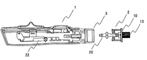
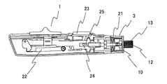
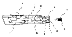
- wearing the puncture device with the puncture needle cartridge concerning one Embodiment of this invention The perspective view of the puncture needle cartridge concerning one Embodiment of this invention
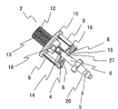
- the perspective view of the puncture needle cartridge concerning one Embodiment of this invention The front view of the puncture needle cartridge concerning one Embodiment of this invention
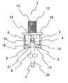
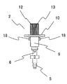
- the side view of the puncture needle cartridge concerning one Embodiment of this invention The top view of the puncture needle cartridge concerning one Embodiment of this invention
- separated the protective cap The reverse view which shows the state which mounted
- the front view which shows the state which discards the puncture needle cartridge concerning one Embodiment of this invention from a puncture device.
- reference numeral 1 denotes a puncture device, and a holding portion 3 into which a puncture needle cartridge 2 is inserted is provided on the distal end side thereof.
- the puncture needle cartridge 2 has a lancet body 6, a skin contact portion 10, and a protective cap 13 as shown in FIGS. 2 to 6.
- the lancet body 6 has a cylindrical shape.
- the lancet body 6 has a puncture needle holding part 4 for holding a puncture needle 7 (see FIGS. 8 and 10 etc.) on the front end side, and has a puncture device mounting part 5 on the rear end side.
- the rear end side of the protective cap 13 is connected to the puncture needle holding portion 4 of the lancet body 6 via the separation portion 14.
- the protective cap 13 covers the tip of the puncture needle 7.
- a cylindrical operation unit 12 is provided on the front end side of the protective cap 13.
- a guide projection 18 for rotating the operation unit 12 is provided behind the operation unit 12.
- the skin contact portion 10 has a disk shape orthogonal to the puncture needle 7 in front of the puncture needle 7 (see FIG. 6 and the like).
- the skin contact portion 10 has an example of a disc shape, but the shape is not limited to a disc and may be a quadrangle or the like.
- the skin contact portion 10 is formed with a circular through hole 11 through which the protective cap 13 is passed.
- the through hole 11 is formed with a notch portion 17 that is notched outward from the through hole 11. Two notches 17 are formed at positions facing each other across the center of the through hole 11. As is understood from FIGS. 6 and 9, the notch 17 is provided for the guide protrusion 18 to pass when the protective cap 13 is removed.
- An extension body 9 extending toward the rear end side is provided near the outer periphery of the skin contact portion 10.
- the extension body 9 is provided in a substantially parallel state with the lancet body 6 at a position facing the through hole 11.
- the extension body 9 is an elongated plate-like member, and the rear side thereof is freely deformable toward the lancet body 6 side.
- the lancet body 6 and the extension body 9 are connected by an elastic body 8.
- One end of the elastic body 8 is integrally connected to the distal end portion of the lancet body 6, and the other end is integrally connected to the rear end portion of the extension body 9.
- the elastic body 8 has a shape in which an elongated plate-like member is folded.
- the elastic body urges the puncture needle so that the tip of the puncture needle is located on the rear end side of the skin contact portion 10 as will be described later with reference to FIGS.
- the elastic body 8 includes a first bent portion 15 bent in a convex shape toward the lancet body 6 and a second bent in a convex shape toward the extended body 9 between the lancet body 6 and the extended body 9.
- a bent portion 16 is provided. Spaces are provided between the first bent portion 15 and the lancet body 6 and between the second bent portion 16 and the extension body 9. For this reason, the rear side of the extension body 9 is freely deformable toward the lancet body 6 side.
- the extension body 9 and two elastic bodies 8 that connect the extension body 9 are provided.
- the number of the extension bodies 9 and the elastic bodies 8 is not limited to two, and three, four, and the like. One or more.
- FIG. 6 is a view of the puncture needle cartridge 2 as viewed from the operation portion 12 side of the protective cap 13
- FIG. 9 is a view of the puncture needle cartridge 2 as viewed from the puncture device mounting portion 5 side.
- a recess 19 is provided on the outer rear surface of the extension body 9 (on the side opposite to the side where the lancet body 6 is provided). The concave portion 19 and the concave portion 20 of the puncture device mounting portion 5 are held by the puncture device 1.
- the lancet body 6, the elastic body 8, the extension body 9, the skin contact portion 10, and the protective cap 13 are integrally formed of synthetic resin.
- the puncture needle cartridge 2 is held by the holding portion 3 of the puncture device 1.
- the rear end side of the puncture needle cartridge 2 is inserted into the holding portion 3, thereby resulting in the state shown in FIG.
- a projection 21 provided on the holding portion 3 is fitted into the recess 19 of the extension 9 of the puncture needle cartridge 2, and a projection (not shown) is fitted into the recess 20 of the puncture device mounting portion 5. Maru. As a result, the puncture needle cartridge 2 is held by the holding portion 3 of the puncture device 1.
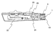
- the urging body 22 is extended from the state shown in FIG. 1 as shown in FIG. As a result, the urging force for pushing the lancet body 6 of the puncture needle cartridge 2 forward is accumulated in the urging body 22.
- the puncture needle 7 since the puncture needle 7 is retracted to the rear side of the skin contact portion 10 and is not exposed, the puncture needle 7 does not damage the finger or the like at this time.
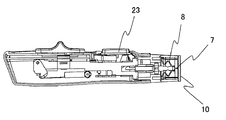
- the puncture needle cartridge 2 is taken out from the holding portion 3 of the puncture device 1 as shown in FIG.
- the discharge operation lever 26 is operated forward, the lancet body 6 of the puncture needle cartridge 2 is pushed forward via a coupling mechanism (not shown). By this extrusion, the holding of the concave portion 19 and the concave portion 20 by the holding portion 3 is easily released. As a result, the puncture needle cartridge 2 can be easily discharged from the holding portion 3 of the puncture device 1 as shown in FIG.
- the puncture needle cartridge 2 discharged from the holding unit 3 of the puncture device 1 is in a state where the skin contact portion 10 covers the front of the puncture needle 7, as shown in FIG.
- the puncture needle cartridge 2 is pinched and inserted into a disposal box (not shown), the finger is not injured.
- the extension 9 part When the puncture needle cartridge 2 is pinched, for example, when it is put into the disposal box, the extension 9 part may be pinched with two fingers. In this case, as shown in FIG. 13, the rear portion of the extension body 9 is pushed and bent toward the lancet body 6 side.
- the elastic body 8 is connected to the rear portion of the extension body 9, and the elastic body 8 is provided with the first and second bent portions 15 and 16 as described above. ing. Therefore, when the rear portion of the extension body 9 is pushed and bent toward the lancet body 6, the first bent portion 15 is pressed against the lancet body 6 and the second bent portion 16 is extended to the extension body. 9 will be pressed.
- the lancet body 6 is substantially fixed to the extension body 9.
- the distal end side of the puncture needle 7 does not protrude forward from the through-hole 11 of the skin contact portion 10, and the safety is extremely high.
- the lancet body 6 is provided with a recess 27 into which the first bent portion 15 is fitted, thereby enhancing the effect of preventing the puncture needle 7 from protruding.
- the tip side of the puncture needle 7 does not protrude forward from the through hole 11 of the skin contact portion 10, and the safety is high.
- the disc-shaped skin contact portion 10 orthogonal to the puncture needle 7 is provided in front of the puncture needle 7. Therefore, when the puncture needle cartridge 2 is removed from the puncture device 1 and discarded, the puncture needle 7 does not accidentally hurt a hand or the like, and the safety becomes high.
- a planar skin contact portion orthogonal to the puncture needle is provided in front of the puncture needle. Therefore, when the puncture needle cartridge is removed from the puncture device and discarded, the hand is not accidentally damaged by the puncture needle, and the safety is improved.
Landscapes
- Health & Medical Sciences (AREA)
- Life Sciences & Earth Sciences (AREA)
- Heart & Thoracic Surgery (AREA)
- Medical Informatics (AREA)
- Biophysics (AREA)
- Pathology (AREA)
- Engineering & Computer Science (AREA)
- Biomedical Technology (AREA)
- Hematology (AREA)
- Physics & Mathematics (AREA)
- Molecular Biology (AREA)
- Surgery (AREA)
- Animal Behavior & Ethology (AREA)
- General Health & Medical Sciences (AREA)
- Public Health (AREA)
- Veterinary Medicine (AREA)
- Measurement Of The Respiration, Hearing Ability, Form, And Blood Characteristics Of Living Organisms (AREA)
Abstract
Description
図1において、1は穿刺器具を示し、その先端側には、穿刺針カートリッジ2が挿入される保持部3が設けられている。
2 穿刺針カートリッジ
3 保持部
4 穿刺針保持部
5 穿刺器具装着部
6 ランセット本体
7 穿刺針
8 弾性体
9 延長体
10 皮膚接触部
11 貫通孔
12 操作部
13 保護キャップ
14 分離部
15 第1の屈曲部
16 第2の屈曲部
17 切欠部
18 ガイド突起
19 凹部
20 凹部
21 突起
22 付勢体
23 操作ボタン
24 ロック機構
25 係止部
26 排出操作レバー
27 凹部
Claims (7)
- 先端側に穿刺針、後端側に穿刺器具装着部を有する柱状のランセット本体と、
前記穿刺針を覆うと共に先端側に延びる形状を有する保護キャップと、
前記穿刺針の先端より前方に配置され、この穿刺針と直交する平面形状を有すると共に前記保護キャップを通す貫通孔が形成された皮膚接触部と、
前記皮膚接触部から後端側に向かって延びる細長い板状の延長体と、
前記延長体と前記ランセット本体とを連結すると共に、前記穿刺針の先端が前記皮膚接触部より後端側に位置するように付勢する弾性体と、
を備える穿刺針カートリッジ。 - 前記延長体の後方はランセット本体側に変形自在とし、前記弾性体は、細長い板状部材が折り畳まれた形状を有しており、前記ランセット本体に向かって凸状に屈曲する屈曲部とランセット本体との間には、空間を有する請求項1に記載の穿刺針カートリッジ。
- 前記延長体の後方はランセット本体側に変形自在とし、前記弾性体は、細長い板状部材が折り畳まれた形状を有しており、前記延長体に向かって凸状に屈曲する屈曲部とランセット本体との間には、空間を有する請求項1または請求項2に記載の穿刺針カートリッジ。
- 前記ランセット本体と、前記弾性体と、前記延長体と、前記皮膚接触部と、前記保護キャップとは合成樹脂によって一体に形成されている請求項1から請求項3のいずれか一つに記載の穿刺針カートリッジ。
- 前記保護キャップは、前記ランセット本体の穿刺針を保持する穿刺針保持部に対して、破断可能な分離部を介して連結されており、
前記保護キャップは、先端側に操作部を有する請求項1から請求項4のいずれか一つに記載の穿刺針カートリッジ。 - 前記延長体を2つ有し、2つの延長体は、前記貫通孔を挟んで対向する位置に設けられている請求項1から請求項5のいずれか一つに記載の穿刺針カートリッジ。
- 請求項1から請求項6のいずれか一つに記載の穿刺針カートリッジを装着する穿刺器具であって、
前記穿刺針カートリッジの穿刺器具装着部が挿入される保持部と、
この保持部に前記穿刺針カートリッジが保持された状態で穿刺針カートリッジのランセット本体に対する付勢力が蓄積される付勢体と、
この付勢体の付勢力を解放する穿刺操作部と、
を有する穿刺器具。
Priority Applications (2)
| Application Number | Priority Date | Filing Date | Title |
|---|---|---|---|
| US14/401,983 US9486166B2 (en) | 2012-05-18 | 2013-04-05 | Puncturing needle cartridge and puncturing instrument |
| JP2014515474A JP5932991B2 (ja) | 2012-05-18 | 2013-04-05 | 穿刺針カートリッジ |
Applications Claiming Priority (2)
| Application Number | Priority Date | Filing Date | Title |
|---|---|---|---|
| JP2012-114375 | 2012-05-18 | ||
| JP2012114375 | 2012-05-18 |
Publications (1)
| Publication Number | Publication Date |
|---|---|
| WO2013171963A1 true WO2013171963A1 (ja) | 2013-11-21 |
Family
ID=49583396
Family Applications (1)
| Application Number | Title | Priority Date | Filing Date |
|---|---|---|---|
| PCT/JP2013/002367 Ceased WO2013171963A1 (ja) | 2012-05-18 | 2013-04-05 | 穿刺針カートリッジ及び穿刺器具 |
Country Status (3)
| Country | Link |
|---|---|
| US (1) | US9486166B2 (ja) |
| JP (2) | JP5932991B2 (ja) |
| WO (1) | WO2013171963A1 (ja) |
Families Citing this family (1)
| Publication number | Priority date | Publication date | Assignee | Title |
|---|---|---|---|---|
| GB2577869A (en) * | 2018-09-28 | 2020-04-15 | Owen Mumford Ltd | A blood sampling device |
Citations (3)
| Publication number | Priority date | Publication date | Assignee | Title |
|---|---|---|---|---|
| JP2009077871A (ja) * | 2007-09-26 | 2009-04-16 | National Institute Of Advanced Industrial & Technology | 針一体型センサ |
| JP2010110625A (ja) * | 2008-10-09 | 2010-05-20 | Panasonic Corp | 穿刺針カートリッジ |
| JP2012085686A (ja) * | 2010-10-15 | 2012-05-10 | Asahi Polyslider Co Ltd | ランセット穿刺デバイス |
Family Cites Families (19)
| Publication number | Priority date | Publication date | Assignee | Title |
|---|---|---|---|---|
| US4990154A (en) * | 1989-06-19 | 1991-02-05 | Miles Inc. | Lancet assembly |
| SE465012B (sv) * | 1989-12-08 | 1991-07-15 | Freja Invest Kommanditbolag | Haaltagningshjaelpmedel foer aastadkommande av punktering av kroppsdelar |
| US5085640A (en) * | 1990-04-06 | 1992-02-04 | Gibbs Andrew H | Non-reusable medical needle apparatus |
| DE4320463A1 (de) | 1993-06-21 | 1994-12-22 | Boehringer Mannheim Gmbh | Blutlanzettenvorrichtung zur Entnahme von Blut für Diagnosezwecke |
| KR0135178Y1 (ko) * | 1995-06-26 | 1999-03-20 | 김인환 | 채혈용 란셋 |
| CA2287757A1 (en) * | 1999-10-29 | 2001-04-29 | Medical Plastic Devices M.P.D. Inc. | Disposable lancet |
| DE10047419A1 (de) * | 2000-09-26 | 2002-04-11 | Roche Diagnostics Gmbh | Lanzettensystem |
| US7288102B2 (en) * | 2003-03-20 | 2007-10-30 | Facet Technologies, Llc | Lancing device with decoupled lancet |
| US20050015019A1 (en) * | 2003-07-18 | 2005-01-20 | Yamatake Corporation | Sampling syringe unit, sampling device and sampling method for sampling blood or body fluid |
| PL207804B1 (pl) * | 2003-07-29 | 2011-02-28 | Htl Strefa Społka Z Ograniczoną Odpowiedzialnością | Przyrząd do nakłuwania |
| US7481818B2 (en) * | 2003-10-20 | 2009-01-27 | Lifescan | Lancing device with a floating probe for control of penetration depth |
| JP2005312763A (ja) * | 2004-04-30 | 2005-11-10 | Arkray Inc | 穿刺針カートリッジ、穿刺器具、先端ユニットおよびアダプタ |
| US20050277849A1 (en) * | 2004-06-10 | 2005-12-15 | Daniel Wong | Vacuum sample expression device |
| US7955347B2 (en) * | 2004-06-25 | 2011-06-07 | Facet Technologies, Llc | Low cost safety lancet |
| DE102004058164B4 (de) * | 2004-12-02 | 2009-04-16 | Roche Diagnostics Gmbh | Stechvorrichtung zur Entnahme von Blut und Verfahren zur Herstellung dafür |
| PL216241B1 (pl) * | 2007-01-10 | 2014-03-31 | Htl Strefa Społka Akcyjna | Urządzenie do nakłuwania skóry pacjenta |
| CA2646261A1 (en) * | 2007-12-14 | 2009-06-14 | Tyco Healthcare Group Lp | Blood collection device with tube retaining structure |
| WO2009129349A2 (en) * | 2008-04-16 | 2009-10-22 | Kim Stanley I | Single-use disposable lancing apparatus and methods |
| US20120116436A1 (en) * | 2010-11-04 | 2012-05-10 | Roche Diagnostics Operations, Inc. | Safety lancet |
-
2013
- 2013-04-05 US US14/401,983 patent/US9486166B2/en active Active
- 2013-04-05 WO PCT/JP2013/002367 patent/WO2013171963A1/ja not_active Ceased
- 2013-04-05 JP JP2014515474A patent/JP5932991B2/ja active Active
-
2016
- 2016-04-28 JP JP2016089966A patent/JP2016179180A/ja active Pending
Patent Citations (3)
| Publication number | Priority date | Publication date | Assignee | Title |
|---|---|---|---|---|
| JP2009077871A (ja) * | 2007-09-26 | 2009-04-16 | National Institute Of Advanced Industrial & Technology | 針一体型センサ |
| JP2010110625A (ja) * | 2008-10-09 | 2010-05-20 | Panasonic Corp | 穿刺針カートリッジ |
| JP2012085686A (ja) * | 2010-10-15 | 2012-05-10 | Asahi Polyslider Co Ltd | ランセット穿刺デバイス |
Also Published As
| Publication number | Publication date |
|---|---|
| US20150142037A1 (en) | 2015-05-21 |
| JPWO2013171963A1 (ja) | 2016-01-12 |
| JP5932991B2 (ja) | 2016-06-08 |
| JP2016179180A (ja) | 2016-10-13 |
| US9486166B2 (en) | 2016-11-08 |
Similar Documents
| Publication | Publication Date | Title |
|---|---|---|
| CN101959459B (zh) | 穿刺装置 | |
| JP4799564B2 (ja) | 皮膚に刺す装置 | |
| CN100591292C (zh) | 利用多刺针单元的刺针装置 | |
| KR101716529B1 (ko) | 일회용 채혈 기구 | |
| EP2985049B1 (en) | Butterfly-type needle assembly and butterfly-type needle protective sleeve | |
| CN100484472C (zh) | 刺血针以及具有其的刺血针装置 | |
| JP2019524324A (ja) | 取換可能なブレードカートリッジを備える安全メス | |
| JP5561713B2 (ja) | 穿刺針カートリッジ | |
| CN103153187B (zh) | 穿刺装置以及构成该穿刺装置的柳叶刀组件和注射器组件 | |
| JP5932991B2 (ja) | 穿刺針カートリッジ | |
| JP6577534B2 (ja) | 穿刺針カートリッジ | |
| WO2015111693A1 (ja) | 穿刺器具 | |
| US9649060B2 (en) | Puncture needle cartridge and puncture device using same | |
| JP5948256B2 (ja) | ランセット・デバイス | |
| JP5930688B2 (ja) | ランセットカートリッジ | |
| CN109106377B (zh) | 注射器 | |
| JP6252981B2 (ja) | ランセットおよびそれを備える穿刺器具 | |
| JP2005253781A (ja) | 穿刺具用キャップ | |
| JP2018079126A (ja) | ランセット | |
| CN115998379A (zh) | 一种活检穿刺装置 | |
| US20090281562A1 (en) | Lancet | |
| CN106540353A (zh) | 蝴蝶针组件 | |
| JP4585040B2 (ja) | 穿刺針カートリッジ | |
| JP5122170B2 (ja) | プロテクタ | |
| JP6811482B2 (ja) | 鞘用抜け止め具 |
Legal Events
| Date | Code | Title | Description |
|---|---|---|---|
| 121 | Ep: the epo has been informed by wipo that ep was designated in this application |
Ref document number: 13791553 Country of ref document: EP Kind code of ref document: A1 |
|
| ENP | Entry into the national phase |
Ref document number: 2014515474 Country of ref document: JP Kind code of ref document: A |
|
| NENP | Non-entry into the national phase |
Ref country code: DE |
|
| WWE | Wipo information: entry into national phase |
Ref document number: 14401983 Country of ref document: US |
|
| 122 | Ep: pct application non-entry in european phase |
Ref document number: 13791553 Country of ref document: EP Kind code of ref document: A1 |