WO2013171821A1 - Dispositif de remplissage d'agent médical - Google Patents
Dispositif de remplissage d'agent médical Download PDFInfo
- Publication number
- WO2013171821A1 WO2013171821A1 PCT/JP2012/062280 JP2012062280W WO2013171821A1 WO 2013171821 A1 WO2013171821 A1 WO 2013171821A1 JP 2012062280 W JP2012062280 W JP 2012062280W WO 2013171821 A1 WO2013171821 A1 WO 2013171821A1
- Authority
- WO
- WIPO (PCT)
- Prior art keywords
- holding body
- container
- holding
- supply
- medicine
- Prior art date
Links
Images


Classifications
-
- A—HUMAN NECESSITIES
- A61—MEDICAL OR VETERINARY SCIENCE; HYGIENE
- A61J—CONTAINERS SPECIALLY ADAPTED FOR MEDICAL OR PHARMACEUTICAL PURPOSES; DEVICES OR METHODS SPECIALLY ADAPTED FOR BRINGING PHARMACEUTICAL PRODUCTS INTO PARTICULAR PHYSICAL OR ADMINISTERING FORMS; DEVICES FOR ADMINISTERING FOOD OR MEDICINES ORALLY; BABY COMFORTERS; DEVICES FOR RECEIVING SPITTLE
- A61J7/00—Devices for administering medicines orally, e.g. spoons; Pill counting devices; Arrangements for time indication or reminder for taking medicine
- A61J7/0076—Medicament distribution means
-
- B—PERFORMING OPERATIONS; TRANSPORTING
- B65—CONVEYING; PACKING; STORING; HANDLING THIN OR FILAMENTARY MATERIAL
- B65B—MACHINES, APPARATUS OR DEVICES FOR, OR METHODS OF, PACKAGING ARTICLES OR MATERIALS; UNPACKING
- B65B39/00—Nozzles, funnels or guides for introducing articles or materials into containers or wrappers
- B65B39/007—Guides or funnels for introducing articles into containers or wrappers
-
- B—PERFORMING OPERATIONS; TRANSPORTING
- B65—CONVEYING; PACKING; STORING; HANDLING THIN OR FILAMENTARY MATERIAL
- B65B—MACHINES, APPARATUS OR DEVICES FOR, OR METHODS OF, PACKAGING ARTICLES OR MATERIALS; UNPACKING
- B65B5/00—Packaging individual articles in containers or receptacles, e.g. bags, sacks, boxes, cartons, cans, jars
- B65B5/10—Filling containers or receptacles progressively or in stages by introducing successive articles, or layers of articles
- B65B5/101—Filling containers or receptacles progressively or in stages by introducing successive articles, or layers of articles by gravity
- B65B5/103—Filling containers or receptacles progressively or in stages by introducing successive articles, or layers of articles by gravity for packaging pills or tablets
-
- B—PERFORMING OPERATIONS; TRANSPORTING
- B65—CONVEYING; PACKING; STORING; HANDLING THIN OR FILAMENTARY MATERIAL
- B65B—MACHINES, APPARATUS OR DEVICES FOR, OR METHODS OF, PACKAGING ARTICLES OR MATERIALS; UNPACKING
- B65B57/00—Automatic control, checking, warning, or safety devices
- B65B57/02—Automatic control, checking, warning, or safety devices responsive to absence, presence, abnormal feed, or misplacement of binding or wrapping material, containers, or packages
- B65B57/06—Automatic control, checking, warning, or safety devices responsive to absence, presence, abnormal feed, or misplacement of binding or wrapping material, containers, or packages and operating to control, or to stop, the feed of articles or material to be packaged
-
- B—PERFORMING OPERATIONS; TRANSPORTING
- B65—CONVEYING; PACKING; STORING; HANDLING THIN OR FILAMENTARY MATERIAL
- B65G—TRANSPORT OR STORAGE DEVICES, e.g. CONVEYORS FOR LOADING OR TIPPING, SHOP CONVEYOR SYSTEMS OR PNEUMATIC TUBE CONVEYORS
- B65G43/00—Control devices, e.g. for safety, warning or fault-correcting
- B65G43/08—Control devices operated by article or material being fed, conveyed or discharged
-
- G—PHYSICS
- G05—CONTROLLING; REGULATING
- G05B—CONTROL OR REGULATING SYSTEMS IN GENERAL; FUNCTIONAL ELEMENTS OF SUCH SYSTEMS; MONITORING OR TESTING ARRANGEMENTS FOR SUCH SYSTEMS OR ELEMENTS
- G05B15/00—Systems controlled by a computer
- G05B15/02—Systems controlled by a computer electric
-
- A—HUMAN NECESSITIES
- A61—MEDICAL OR VETERINARY SCIENCE; HYGIENE
- A61J—CONTAINERS SPECIALLY ADAPTED FOR MEDICAL OR PHARMACEUTICAL PURPOSES; DEVICES OR METHODS SPECIALLY ADAPTED FOR BRINGING PHARMACEUTICAL PRODUCTS INTO PARTICULAR PHYSICAL OR ADMINISTERING FORMS; DEVICES FOR ADMINISTERING FOOD OR MEDICINES ORALLY; BABY COMFORTERS; DEVICES FOR RECEIVING SPITTLE
- A61J1/00—Containers specially adapted for medical or pharmaceutical purposes
- A61J1/03—Containers specially adapted for medical or pharmaceutical purposes for pills or tablets
Definitions
- the present invention relates to a drug filling device, and more particularly to a drug filling device for filling a container with a drug.
- a device for filling a container with a medicine a resin tablet case having a discharge drum for discharging the medicine from a storage container for storing the medicine, and a resin that directly receives the medicine discharged from the tablet case and guides it forward.
- a medicine supply device including a manufactured chute (see, for example, Japanese Patent Laid-Open No. 2002-291845 (Patent Document 1)).
- Patent Document 1 In the medicine supply device described in Japanese Patent Laid-Open No. 2002-291845 (Patent Document 1), when filling a container with a medicine, an operator needs to manually move the containers one by one under the chute outlet. Therefore, there was a problem that took time.
- the present invention has been made in view of the above problems, and a main object thereof is to provide a drug filling device that can reduce the labor of an operator when filling a container with a drug.
- the drug filling device includes a supply device, a holding body, a transport device, and a detection unit.
- the supply device supplies a target drug to a container that can be filled with the drug.
- the holding body has a plurality of holding portions capable of holding the container.
- the transport device transports the holding body.
- the transport device moves the holding body to a supply position where the medicine can be supplied from the supply device to the container held in any of the plurality of holding units.
- the detection unit detects a holding body located immediately upstream of the supply position.
- the holding body has a plurality of detected portions corresponding to each of the plurality of holding portions, and the detecting portion detects a detected portion of the holding portion located immediately upstream of the supply position. May be.
- the drug filling device may include a container detection unit that detects that the container is held by the holding unit.
- the medicine filling device further includes a control unit that controls the supply device and the transport device, and the control unit receives a detection result of the detection unit indicating that the holding body is located immediately upstream of the supply position.
- the transport device may be controlled to stop the holding body at the supply position.
- the medicine filling device includes a container detection unit that detects that the container is held in the holding unit, and the control unit holds the container in the holding unit when the holding body is stopped at the supply position.
- the supply device may be controlled in response to the detection result of the container detection unit indicating that the medicine is supplied from the supply device to the container.
- control unit may resume transport of the holding body by the transport device when the supply of the drug from the supply device to the container is completed.
- the transport device may have a belt, and the holding body may be placed on the belt and transported.
- the medicine filling apparatus of the present invention since the holder holding a container that can be filled with medicine can be transported and the medicine can be automatically supplied to the container from the supply device, the labor of the operator can be reduced. .
- FIG. 1 It is a side view which shows schematic structure of the chemical
- FIG. 1 is a side view showing a schematic configuration of a drug filling device 1 of the present embodiment.
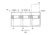
- FIG. 2 is an enlarged view of the holding body 20 shown in FIG.
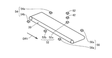
- FIG. 3 is a schematic diagram illustrating the arrangement of each detection unit with respect to the transport device 30.
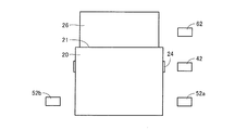
- FIG. 4 is a schematic diagram showing the arrangement of the detection units with respect to the holding body 20 and the container 26.
- the drug filling device 1 is a device for automating the operation of filling a container 26 with a solid drug such as a tablet or a capsule or a drug individually packaged for each administration unit.
- the drug filling device 1 includes a supply device 10 that supplies a target drug to a container 26 and a transport device 30 that transports a holding body 20 that holds the container 26.
- the container 26 has a rectangular box shape with a relatively small thickness in consideration of convenience during delivery. As long as the container 26 can be filled with the target medicine, the shape of the container 26 is not limited to a box shape.
- the container 26 may be a substantially cylindrical vial, or a container 26 having any other shape may be used.
- the supply device 10 has a medicine cassette in which various kinds of medicines are stored for each kind.
- the medicine cassette is detachably provided in the supply device 10.
- the supply device 10 may be capable of holding a plurality of drug cassettes such as 128 or 256 at the same time. In this case, a plurality of drugs can be easily dispensed from the supply device 10 for each type. Therefore, the dispensing of the medicine can be completed in a short time according to the prescription including a plurality of medicines.
- the supply device 10 may be configured to be able to hold one medicine cassette and the user who uses the device may replace the necessary medicine cassette each time. In this case, the supply device 10 can be downsized, so the supply device 10 cost reduction and space saving can be achieved.
- a discharge port for discharging the medicine is formed in the lower part, and a hopper 12 is arranged at a position facing the discharge port.
- the medicine dispensed from the medicine cassette is discharged from the discharge port, further falls via the hopper 12 provided below the supply device 10, and is supplied to the container 26.
- the transport device 30 transports the holding body 20, so that the container 26 moves below the supply device 10.
- An upper opening that communicates the inside and the outside of the container 26 is formed on the upper side of each container 26.
- the holding body 20 has a plurality of holding portions 22 that can hold the container 26.
- One holding part 22 holds one container 26, and the holding body 20 having a plurality of holding parts 22 holds a plurality of containers 26 as a whole.
- the plurality of containers 26 are arranged in the moving direction of the holding body 20 conveyed by the conveying device 30 and are held by the holding body 20.
- the plurality of holding portions 22 are formed side by side in the moving direction of the holding body 20.
- the internal space of the holding body 20 is partitioned into three sections by a partition wall 23, and each of the three sections is provided so as to accommodate the container 26. Accordingly, the holding body 20 is provided with three holding portions 22a, 22b, and 22c. Openings are formed in the holding portions 22a, 22b, and 22c on the ceiling portion 21 side of the holding body 20.
- the container 26 extends from the inside of the holding body 20 to the outside above the holding body 20 through the opening. The upper end portion of the container 26 is disposed outside the holding body 20.
- the outer wall surface of the side part of the holding body 20 is provided with a belt-like part extending along the transport direction DR1 of the holding body 20 by the transport device 30.
- the belt-like portion has light color portions having relatively light colors and dark color portions having relatively dark colors alternately in the transport direction DR1.
- the dark color portion is provided on the downstream side of the holding unit 22 in the transport direction DR1.
- the upstream end of the dark color portion in the transport direction DR1 is provided on the downstream side of the transport direction DR1 with respect to the center line of the holding unit 22 in the transport direction DR1.
- the end of the dark color portion on the upstream side in the transport direction DR1 has a function as the detected portion 24 detected by the holding body position detecting portion 42 described later.
- a plurality of the detected parts 24 are continuously provided with a predetermined interval in the transport direction DR1 of the holding body 20.
- the interval between adjacent detected parts 24 in the transport direction DR1 is typically substantially the same as the dimension of the holding part 22 in the transport direction DR1.
- the detected portion 24 is not limited to the configuration in which the color of the belt-shaped portion is formed, and the detected portion 24 may have any configuration as long as the position of the holding body 20 in the transport direction DR1 can be detected. Good.
- the transport device 30 moves the container 26 held by the holding unit 22 of the holding body 20 to a position where the medicine can be supplied from the supply device 10 to the container 26.
- the transport device 30 sequentially moves the plurality of containers 26 to a position where the medicine can be supplied from the supply device 10, and supplies the medicine to the containers 26 at the position.
- the holding body 20 is temporarily stopped.
- the holding body 20 is a known belt conveyor having a belt 32 and a pair of pulleys 34 and 36.
- the holding body 20 is placed on the upper side of the belt 32.
- the holding body 20 is conveyed in the conveyance direction DR1.
- the holding body 20 has a transport direction DR1 as a direction from one of the pair of pulleys 34 and 36 provided at both ends of the belt 32 toward the other, for example, a direction from the pulley 34 to the pulley 36. Transport.
- the transport device 30 may be capable of transporting the holding body 20 in both directions. That is, in addition to the transport direction DR1, the transport device 30 also holds the holding body in a direction from the other of the pair of pulleys 34, 36 in the direction opposite to the transport direction DR1, for example, from the pulley 36 to the pulley 34. 20 may be transportable. Since the transport device 30 is configured to be able to switch the direction in which the holding body 20 is transported, the user using the medicine filling device 1 can select either direction as the transport direction DR1. Thereby, according to the situation where the medicine filling device 1 is actually installed, the holding body 20 can be transported in a more appropriate direction and the container 26 can be filled with the medicine.
- the transport device 30 is not limited to a belt conveyor, and may have any configuration as long as the holder 20 can be transported in the transport direction DR1.
- the transport device 30 may have a robot arm whose position can be finely adjusted in the transport direction DR1, and the robot arm may hold the holding body 20 and move it in the transport direction DR1.
- the drug filling device 1 includes three sets of holding body detection units, that is, an upstream holding body detection unit 54, a central holding body detection unit 52, and a downstream holding body detection unit 56.
- the upstream holding body detection unit 54, the central holding body detection unit 52, and the downstream side holding body detection unit 56 are arranged in this order in the transport direction DR1.
- the upstream holding body detection unit 54 is provided on the upstream side in the transport direction DR1 with respect to the central holding body detection unit 52.
- the downstream holding body detection unit 56 is provided downstream of the central holding body detection unit 52 in the transport direction DR1.
- the central holding body detection unit 52 holds the holding body 20.
- the upstream holding body detection unit 54 detects the holding body 20 at the transfer start position where the transfer device 30 starts to transfer the holding body 20.
- the downstream holding body detection unit 56 detects the holding body 20 at the conveyance end position where the conveyance device 30 stops the holding body 20 and ends the conveyance of the holding body 20.
- the center holder detection unit 52 is a transmissive optical sensor having a light emitting unit 52a and a light receiving unit 52b.
- the upstream holding body detection unit 54 is a transmissive optical sensor having a light emitting unit 54a and a light receiving unit 54b.
- the downstream holding body detection unit 56 is a transmissive optical sensor having a light emitting unit 56a and a light receiving unit 56b.
- the light generated by each of the light emitting units 52a, 54a, and 56a is received by the light receiving units 52b, 54b, and 56b, respectively.
- the light emitting unit 52 a and the light receiving unit 52 b are arranged at positions facing the bottom side of the side surface of the holding body 20 in the vertical direction (vertical direction in FIG. 4).
- the other light emitting units 54a and 56a and the light receiving units 54b and 56b are also arranged at the same position as the light emitting unit 52a and the light receiving unit 52b shown in FIG. 4 in the vertical direction.
- the fact that the corresponding light receiving parts 52b, 54b, 56b receive the light generated by the light emitting parts 52a, 54a, 56a means that the holding body 20 does not exist at the position where each holding body detection part is provided.
- the fact that the corresponding light receiving portions 52b, 54b, 56b do not receive the light generated by any of the light emitting portions 52a, 54a, 56a means that the light is blocked by the holding body 20. That is, the holding body 20 exists at a position where the holding body detection unit having a light receiving unit that does not receive light is provided.
- the medicine filling device 1 includes a holding body position detection unit 42 as a detection unit that detects the detected part 24 provided in the holding body 20.
- the holding body position detection unit 42 is a reflection type optical sensor that irradiates light to the above-described band-shaped portion of the holding body 20 and detects light reflected by the band-shaped portion.
- the belt-shaped portion has a light color portion and a dark color portion, and the reflection of light from the light color portion is different from the light reflection from the dark color portion. It is possible to detect which of the light is irradiated.
- the end of the dark color part that forms the boundary from the dark color part to the light color part functions as the detected part 24, and the holder position detection unit 42 changes the reflected light from the dark color part to the reflected light from the light color part.
- the detected part 24 is detected by detecting the change in the above.
- the holding body 20 When the detected part 24 is detected by the holding body position detection unit 42, the holding body 20 is in the conveyance direction DR1 with respect to the container 26 to be held by the holding part 22 corresponding to the detected detected part 24. It exists immediately upstream of the position where the medicine can be supplied from the supply device 10.
- the medicine filling device 1 also includes a container detection unit 62 that detects that the container 26 is held by the holding unit 22 of the holding body 20.
- the container detection unit 62 is a reflection type optical sensor that irradiates light to the container 26 held by the holding unit 22 of the holding body 20 and detects light reflected by the outer wall surface of the container 26. If the container 26 is not held by the holding unit 22, the container detection unit 62 does not detect reflected light. On the other hand, if the container 26 is held by the holding unit 22, the light applied to the container 26 is reflected, and therefore the container detection unit 62 detects the presence or absence of the container 26 by detecting the reflected light.
- the container detection part 62 is arrange
- each detection unit is a magnetic sensor capable of detecting a change in the magnetic field
- a magnet is attached to the holding body 20 and the container 26, and the change in the magnetic field when the holding body 20 and the container 26 are close to the magnetic sensor is detected.
- the holder 20 and the container 26 may be detected.
- FIG. 5 is a block diagram showing a schematic configuration relating to the control of the medicine filling apparatus 1.
- the medicine filling device 1 includes a control device 80 that controls operations of the supply device 10 and the transport device 30.
- a detection result of the detected part 24 by the holding body position detection unit 42 that is, a signal indicating that the holding body position detection unit 42 detects or does not detect the detected part 24 is input to the control device 80.
- the detection result of the holding body 20 by the upstream holding body detection unit 54, the central holding body detection unit 52, and the downstream holding body detection unit 56 that is, a signal indicating which position the holding body 20 is in the transport direction DR1 is: Input to the controller 80.
- a detection result of the container 26 by the container detection unit 62 that is, a signal indicating that the container 26 is held or not held by the holding unit 22 of the holding body 20 is input to the control device 80.
- a user who operates the medicine filling device 1 controls each setting value such as the transport direction of the holding body 20 by the transport device 30 and the quantity of the medicine filled in the container 26 from the input unit 82 such as an input key or a touch panel. Enter 80.
- the supply device 10 includes a medicine detection unit 14.
- the medicine detection unit 14 detects the medicine actually supplied from the supply device 10 to the container 26.
- the medicine detection unit 14 is provided, for example, at a discharge port from which the medicine is discharged from the supply device 10 and detects a medicine that falls through the discharge port. Information on the medicine supplied from the supply device 10 to the container 26 detected by the medicine detection unit 14 is input to the control device 80.
- the supply device 10 has a supply motor 18 that is a power source for performing an operation of discharging the medicine from the supply device 10.
- the conveyance device 30 includes a conveyance motor 38 that is a power source for rotating one or both of the pulleys 34 and 36 to move the belt 32.
- the control device 80 transmits a control signal for controlling the rotational speed of the supply motor 18 to the supply motor 18, and transmits a control signal for controlling the rotational speed of the transport motor 38 to the transport motor 38.
- the control program for operating the medicine filling device 1 is recorded in the memory 84.
- the setting value input from the input unit 82 to the control device 80 and the detection result input from each detection unit to the control device 80 are also recorded in the memory 84.
- the control device 80 reads data from the memory 84 or writes data to the memory 84 as needed.
- the control device 80 controls the operation of the supply device 10 and the operation of the transport device 30 based on the control program and each detection result of each detection unit.
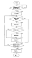
- FIG. 6 is a flowchart showing an operation of supplying a medicine from the supply device 10 to the container 26.
- step (S10) it is determined whether or not the holding body 20 is detected at the conveyance start position.
- the upstream holding body detection unit 54 described above is provided at the conveyance start position, and is held at the conveyance start position while the light receiving unit 54b receives the light generated by the light emitting unit 54a of the upstream holding body detection unit 54. It is determined that the body 20 does not exist.
- the determination in step (S10) is repeated until the holding body 20 is detected at the conveyance start position.
- step (S20) a control signal for driving the transfer motor 38 is sent from the control device 80 to the transfer motor 38, and the transfer of the holding body 20 by the transfer device 30 is performed. Is started.
- step (S30) it is determined whether or not the detected portion 24 has been detected.
- the holding body position detection unit 42 detects the detected part 24, the holding body 20 then moves by a predetermined distance, the conveyance device 30 stops at that position, and the holding body 20 stops conveyance (step (S ⁇ b> 40). )).
- control may be performed so that the holding body 20 continues to move for a predetermined time after the holding body position detection unit 42 detects the detected part 24.
- the control device 80 temporarily stops the transfer of the holding body 20 by the transfer device 30 based on the detection result.
- the holding body 20 is the holding unit 22 that is the most downstream in the transport direction DR1 among the plurality of holding units 22 (that is, the holding unit 22 that is the farthest from the transport start position and closest to the transport end position, and
- the container 26 held by the holding part 22a is stopped at a position where the medicine can be supplied from the supply device 10.
- the arrangement of the holding body 20 that can supply the medicine from the supply device 10 to the container 26 held in any of the plurality of holding units 22 is referred to as a supply position L.
- the container 26 to be held by any one of the plurality of holders 22 is present at a position where the medicine can be supplied from the supply device 10. To do.
- the container 26 When the holding body 20 is stopped at the supply position L, if the container 26 is held by the corresponding holding portion 22, the container 26 is disposed directly below the hopper 12, and is supplied via the hopper 12. The container 26 receives the medicine falling from 10 and can supply the medicine to the container 26. Even when the holding body 20 is stopped at the supply position L, if the container 26 is not held by the corresponding holding portion 22, the container 26 cannot receive the medicine falling from the supply device 10. Note that no drug is supplied from the device 10 to the container 26.
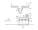
- FIG. 7 is a partial cross-sectional view showing a state in which the holding body 20 is located immediately upstream of the first supply position L1.
- the holding body 20 of the present embodiment described with reference to FIG. 2 has three holding portions 22, and a total of three containers 26 can be held in each holding portion 22. Therefore, there is a supply position L corresponding to each of the three containers 26.
- a supply position L at which the medicine can be supplied to the container 26 to be held by the holding portion 22a is defined as a first supply position L1.
- a supply position L at which the medicine can be supplied to the container 26 to be held by the holding portion 22b is defined as a second supply position L2.
- a supply position L at which the medicine can be supplied to the container 26 to be held by the holding portion 22c is defined as a third supply position L3.
- the holding body 20 is at a position slightly away from the first supply position L1 on the upstream side in the transport direction DR1.
- the holding body position detection unit 42 receives the reflected light from which the detection light 74 applied to the detected part 24 is reflected, so that the holding body 20 is positioned immediately before the first supply position L1 shown in FIG. Detect that The holding body position detection unit 42 detects the position of the holding body 20 by detecting the detected part 24, and inputs the detection result to the control device 80.
- the control device 80 receives the detection result of the holding body position detection unit 42, controls the conveyance device 30, reduces the conveyance speed, and stops the holding body 20 at the first supply position L1.
- the distance in the conveyance direction DR1 between the position of the holding body 20 where the detected part 24 is detected by the holding body position detection unit 42 and the supply position L is based on the detection result of the holding body position detection unit 42 and the transfer device 30.
- the distance is sufficient for the holder 20 to be reliably stopped at the supply position L. That is, the holding body 20 is sufficiently decelerated until the holding body 20 reaches the supply position L after the holding body position detection unit 42 detects the detected part 24, and the holding body 20 is surely brought to the supply position L. It is necessary to secure a distance that can be stopped.
- step (S50) it is determined whether or not the container 26 has been detected.
- the holding body 20 is stopped at the first supply position L1 by the conveyance stop in step (S40). At this time, it is determined based on the detection result of the container detection unit 62 whether the container 26 is held by the corresponding holding unit 22a.
- the container detection unit 62 detects the container 26
- the container 26 is present at a position facing the hopper 12, so that the process proceeds to step (S60), and the supply device 10 moves to the container 26 held by the holding unit 22a.
- the drug is supplied.
- step (S60) a control signal is sent from the control device 80 shown in FIG. 5 to the supply motor 18, the supply motor 18 is driven, and a predetermined type and quantity of medicine are discharged from the supply device 10.
- the medicine detection unit 14 detects that a predetermined quantity of medicine has been discharged from the supply device 10, the supply motor 18 stops and the supply of medicine stops.
- step (S70) the conveyance of the holding body 20 by the conveyance device 30 is resumed.
- step (S50) if the container detection unit 62 does not detect the container 26, the container 26 is not held in the holding unit 22a, so that the medicine supply in step (S60) is not performed and the step (S50) is performed as it is. Proceeding to S70), the conveyance of the holder 20 is resumed.
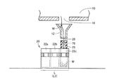
- FIG. 8 is a partial cross-sectional view showing a state in which the holding body 20 is located at the first supply position L1.
- the detection light 76 of the container detection unit 62 is irradiated to a position where the container 26 to be held by the holding unit 22a protrudes upward from the holding unit 22.
- the detection light 76 of the container detection unit 62 is not reflected on the outer surface of the container 26, and the container detection unit 62 does not detect the reflected light. Accordingly, the container detection unit 62 detects that the container 26 is not held by the holding unit 22a, and inputs the detection result to the control device 80.
- the control device 80 receives the detection result of the container detection unit 62, and controls the supply device 10 so as not to supply the medicine at the first supply position L1. As a result, the medicine is not discharged from the supply device 10 when the holding body 20 is in the first supply position L1. Therefore, in the flowchart of FIG. 6, NO is determined in step (S50), step (S60) is skipped, and the process proceeds directly from step (S50) to step (S70), and the conveyance of holding body 20 is resumed. .
- step (S80) After resuming the conveyance of the holding body 20, it is next determined in step (S80) whether or not the holding body 20 has been detected at the conveyance end position.
- the downstream holding body detection unit 56 described above is provided at the conveyance end position, and is held at the conveyance end position while the light receiving unit 56b receives light generated by the light emitting unit 56a of the downstream holding body detection unit 56. It is determined that the body 20 does not exist. If the holding body 20 has not reached the conveyance end position, the process returns to step (S30), and it is determined again whether or not the detected portion 24 has been detected.
- the holding body position detection unit 42 detects the next second detected part 24, the holding body 20 is stopped from being conveyed in step (S40).
- the holding body 20 stops at the second supply position L2 among the supply positions L. That is, in the holding body 20, the container 26 is held by the second holding portion 22 from the downstream side in the transport direction DR1 among the plurality of holding portions 22 (that is, the holding portion 22b of the three holding portions 22 shown in FIG. 2). Assuming that the medicine is supplied from the supply device 10 to the container 26 held by the holding portion 22b, the operation stops.
- FIG. 9 is a partial cross-sectional view showing a state in which the holding body 20 is located immediately upstream of the second supply position L2.
- the holding body 20 shown in FIG. 9 is located immediately upstream in the transport direction DR1 with respect to the second supply position L2.
- the holding body 20 is at a position slightly away from the second supply position L2 in the transport direction DR1 on the upstream side.
- the detection light 74 for detecting the position of the holding body 20 is irradiated from the holding body position detection unit 42 to the holding body 20 at the position shown in FIG. 9, the detection light 74 is applied to the second detected part 24. Irradiated.
- the holding body position detection unit 42 receives the reflected light reflected from the detection light 74 irradiated to the second detected part 24, so that the holding body 20 immediately before the second supply position L2 shown in FIG. It is detected that it is located at. Accordingly, the holding body position detection unit 42 detects the position of the holding body 20 and inputs the detection result to the control device 80.
- the control device 80 receives the detection result of the holding body position detection unit 42, controls the conveyance device 30, reduces the conveyance speed, and stops the holding body 20 at the second supply position L2.
- step (S50) the container 26 is detected in step (S50), and if the container 26 is held by the holding unit 22b, the medicine is supplied to the container 26 held in the holding unit 22b in step (S60). .
- step (S70) the conveyance of the holder 20 is resumed (step (S70)).
- FIG. 10 is a partial cross-sectional view showing a state in which the holding body 20 is located at the second supply position L2.
- the detection light 76 of the container detecting unit 62 is irradiated to a position where the container 26 to be held by the holding unit 22b protrudes upward from the holding unit 22.
- the detection light 76 of the container detection unit 62 is not reflected on the outer surface of the container 26, and the container detection unit 62 does not detect the reflected light. Accordingly, the container detection unit 62 detects that the container 26 is not held by the holding unit 22 b and inputs the detection result to the control device 80.
- the control device 80 receives the detection result of the container detection unit 62, and controls the supply device 10 so as not to supply the medicine at the second supply position L2. As a result, the medicine is not discharged from the supply device 10 when the holding body 20 is in the second supply position L2. Therefore, in the flowchart of FIG. 6, NO is determined in step (S50), step (S60) is skipped, and the process proceeds directly from step (S50) to step (S70), and the conveyance of holding body 20 is resumed. .
- step (S80) it is determined again whether the holding body 20 is detected at the conveyance end position. At this time, since the holding body 20 has not yet reached the conveyance end position, the process returns to step (S30), and the container 26 is held by the third holding portion 22 (holding portion 22c shown in FIG. 2) according to the above-described steps. If so, the medicine is supplied to the container 26 held by the holding part 22c.
- FIG. 11 is a partial cross-sectional view showing a state in which the holding body 20 is located immediately upstream of the third supply position L3.
- the holding body 20 shown in FIG. 11 is located immediately upstream in the transport direction DR1 with respect to the third supply position L3.
- the holding body 20 is at a position slightly away from the third supply position L3 in the transport direction DR1 on the upstream side.
- the holding body position detection unit 42 receives the reflected light reflected by the detection light 74 applied to the third detected part 24, so that the holding body 20 immediately before the third supply position L3 shown in FIG. It is detected that it is located at. Accordingly, the holding body position detection unit 42 detects the position of the holding body 20 and inputs the detection result to the control device 80.
- the control device 80 receives the detection result of the holding body position detection unit 42, controls the conveyance device 30, reduces the conveyance speed, and stops the holding body 20 at the third supply position L3.
- FIG. 12 is a partial cross-sectional view showing a state in which the holding body 20 is located at the third supply position L3.
- the detection light 76 of the container detection unit 62 is irradiated to a position where the container 26 held by the holding unit 22c protrudes upward from the holding unit 22.
- the detection light 76 of the container detection unit 62 is reflected by the outer surface of the container 26, and the container detection unit 62 detects the reflected light. Accordingly, the container detection unit 62 detects that the container 26 is held by the holding unit 22 c and inputs the detection result to the control device 80. Therefore, in the flowchart of FIG. 6, a determination of YES is made in step (S50), the process proceeds from step (S50) to step (S60), and the medicine is supplied to the container 26.
- the control device 80 receives the detection result of the container detection unit 62, and controls the supply device 10 so as to supply the medicine at the third supply position L3.
- a control signal for driving the supply motor 18 is sent from the control device 80 to the supply motor 18, and the medicine M is discharged from the supply device 10.
- the drug M is discharged from the supply device 10 via the discharge port 16 formed in the supply device 10, and the drug M dropped from the supply device 10 is received by the hopper 12.
- the drug M passes through the hopper 12 and further falls, and is supplied into the container 26 held by the holding unit 22c via the upper opening 28 formed in the container 26. In this way, a predetermined type and quantity of medicine M is filled in the container 26 held in the holding portion 22c.
- step (S70) the conveyance of the holder 20 is resumed.
- step (S80) In the determination at the third step (S80) immediately after the subsequent resumption of conveyance, the holding body 20 has not reached the conveyance end position, so that the process returns to step (S30) again and the detected portion 24 is detected. Judgment is made. At this time, since the holding body 20 has three holding portions 22 and the conveyance stop of the holding body 20 at the three supply positions L corresponding to the three holding portions 22 has already been completed, the detected portion 24 thereafter detects It will never be done. Therefore, the process proceeds directly from step (S30) to step (S80), and the determination in step (S80) is performed again.
- the downstream holding body detection unit 56 described above is provided at the conveyance end position, and is held at the conveyance end position while the light receiving unit 56b receives light generated by the light emitting unit 56a of the downstream holding body detection unit 56. It is determined that the body 20 does not exist.
- the holding body 20 continues to be conveyed until the holding body 20 reaches the conveyance end position and the holding body 20 is detected at the conveyance end position.
- the process proceeds to step (S90), and the conveyance of the holding body 20 is completed. In this way, the operation of the medicine filling apparatus 1 that supplies medicine from the supply apparatus 10 to the container 26 is completed.
- the holding body 20 has a plurality of holding portions 22, each holding portion 22 is provided so as to hold a container 26, and the transport device 30 is The holding unit 22 capable of holding a plurality of containers 26 is conveyed. In this way, each of the one or a plurality of containers 26 held by the holding body 20 is filled with an appropriate quantity of an appropriate type of drug, so that an optimum group in the type and / or quantity of the drug is obtained. It can be managed as a unit.
- a plurality of types of drugs to be administered to one patient can be collected in one holder 20 by filling a plurality of containers 26 held in one holder 20 with different types of drugs.
- the prescription before handing the medicine to the patient can be easily compared with the medicine.
- one or a plurality of holding bodies 20 are assigned to each pharmacy or hospital so that the type and quantity of the missing drug can be easily verified. Can do.
- it is possible to appropriately manage the supply of medicine by assigning the holding body 20 to each ward or ward, in addition to the hospital as one unit.
- the holding body 20 is conveyed by the conveying device 30, and the holding body 20 stops at the supply position L.
- the control device 80 controls the transport device 30 so that the holding body 20 is stopped at the supply position L according to the detection result of the holding body position detection unit 42 detecting the detected portion 24. Accordingly, the holder 20 can be reliably stopped at a position where the medicine can be supplied from the supply device 10 to the container 26, and the medicine can be automatically and sequentially supplied to the plurality of containers 26. Since the holding body 20 holding the container 26 that can be filled with the medicine is transported by the transport device 30 and the medicine can be automatically supplied from the supply device 10 to the container 26, the operator when filling the container 26 with the medicine Can be greatly reduced.
- the holding body 20 is provided with a plurality of detected portions 24 corresponding to the plurality of holding portions 22, and the detected portions 24 are provided downstream of the holding portion 22 in the transport direction DR1.
- the holding body position detection unit 42 detects the detected part 24, it is reliably detected that the holding body 20 is immediately upstream of the supply position L.
- the holding body 20 is stopped at a position advanced by a predetermined distance, whereby the stop position of the holding body 20 is changed to the supply position L.
- the holding body 20 is temporarily stopped at each of the plurality of supply positions L, and the medicine is transferred from the supply device 10 to the container 26. Can be supplied.
- the container detection unit 62 detects that the container 26 is held by the holding unit 22. Based on the detection result of the container detection unit 62 when the holding body 20 is stopped at the supply position L, when it is detected that the container 26 is held by the target holding unit 22, the medicine is placed in the container 26. Supplied. When the container detection unit 62 does not detect the container 26, the medicine is not supplied from the supply device 10. Thereby, it is possible to reliably prevent the medicine from being discharged from the supply device 10 when there is no container 26 that can receive the medicine supplied from the supply device 10.
- FIG. 13 is a graph showing the relationship between the position of the holding body 20 and the conveyance speed.
- the horizontal axis of the graph shown in FIG. 13 indicates the position in the transport direction DR1 of the holding body 20 transported by the transport apparatus 30, and the vertical axis indicates the transport speed of the transport apparatus 30 that transports the holding body 20.
- the medicine filling device 1 is provided with the upstream holding body detection unit 54 that detects the holding body 20 at the transfer start position upstream of the supply position L in the transfer direction DR1.
- the control device 80 starts conveying the holding body 20 by the transfer device 30.
- the control device 80 sets the conveyance speed of the holding body 20 by the conveyance device 30 to the first conveyance speed V1. While the upstream holding body detection unit 54 detects the holding body, the transfer speed of the transfer device 30 is maintained at the first transfer speed V1. When the upstream holding body detection unit 54 does not detect the holding body 20, the control device 80 reduces the conveyance speed of the conveyance apparatus 30 to the second conveyance speed V ⁇ b> 2 that is lower than the first conveyance speed V ⁇ b> 1.
- the holding body 20 is transported at the first transport speed V1 having a relatively high transport speed in a predetermined distance after the transport of the holding body 20 to the supply position L after the start of transport. Therefore, the time required for transporting the holding body 20 from the transport start position to the supply position L can be shortened.
- the conveyance speed is controlled to be reduced to the second conveyance speed V2 so that the holding body 20 is conveyed.
- the medicine filling device 1 is provided with a central holding body detection unit 52 that can detect the holding body 20 when the holding body 20 is at the supply position L, and the control device 80 includes a central holding body detection unit 52 that holds the holding body 20. During the detection, the set value of the transport speed when transporting the holding body 20 is kept at the second transport speed V2. Accordingly, it is possible to more easily stop the holding body 20 at the supply position L when the detected portion 24 is detected.
- the conveyance of the holding body 20 is stopped.
- the holding body 20 of the present embodiment has three holding portions 22 and has three detected portions 24 corresponding to the holding portions 22. Therefore, the holding body 20 is temporarily stopped at the three positions of the first supply position L1, the second supply position L2, and the third supply position L3.
- the set value of the conveyance speed before deceleration for stopping the holding body 20 at the supply position L is the second conveyance speed V2, and the set value of the conveyance speed after acceleration after resuming the conveyance from the supply position L is the same as that of the second conveyance speed V2.
- the control device 80 sets the transport speed of the transport device 30 to the third transport speed V3 that is higher than the second transport speed V2 when the central holder detection unit 52 no longer detects the retainer 20.
- the holder 20 is transported at the third transport speed V3 having a relatively high transport speed while moving from the supply position L to the transport end position. .
- the third transport speed V3 may be a speed different from the first transport speed V1, as shown in FIG. 13, or may be the same speed as the first transport speed V1.
- the drug filling device 1 is provided with a downstream holding body detection unit 56 that detects the holding body 20 at a conveyance end position downstream of the supply position L in the conveyance direction DR1.
- the control device 80 ends the conveyance of the holding body 20 by the conveyance device 30 and stops the holding body 20.
- the control device 80 further prohibits the conveyance of the holding body 20 by the conveyance device 30 while the downstream holding body detection unit 56 detects the holding body 20. If the transport device 30 inadvertently starts transporting the retainer 20 when the retainer 20 is at the transport end position, the retainer 20 may fall from the transport device 30. By prohibiting resumption of conveyance when the holding body 20 is at the conveyance end position, it is possible to reliably prevent the holding body 20 from dropping from the conveyance device 30.
- the holding body 20 is provided with the three holding portions 22 and the holding body 20 can hold up to three containers 26 at the same time, but is not limited to this configuration.
- the holding body 20 may have a larger number of holding parts 22 and may hold a larger number of containers 26 at the same time as the number of holding parts 22 increases.
- a plurality of types of holding bodies 20 having different quantities of holding portions 22 may be prepared, and a user operating the medicine filling device 1 may be able to select the holding bodies 20 as appropriate.
- 1 drug filling device 10 supply device, 18 supply motor, 20 holding body, 22, 22a, 22b, 22c holding unit, 24 detected unit, 26 container, 30 transporting device, 38 transporting motor, 42 holding unit position detecting unit, 52 central holding body detection unit, 54 upstream holding body detection unit, 56 downstream holding body detection unit, 62 container detection unit, 80 control device, DR1 transport direction, L supply position, L1 first supply position, L2 second Supply position, L3 third supply position, M drug, V1 first transport speed, V2 second transport speed, V3 third transport speed.
Landscapes
- Engineering & Computer Science (AREA)
- Mechanical Engineering (AREA)
- General Engineering & Computer Science (AREA)
- Physics & Mathematics (AREA)
- General Physics & Mathematics (AREA)
- Automation & Control Theory (AREA)
- Health & Medical Sciences (AREA)
- Life Sciences & Earth Sciences (AREA)
- Animal Behavior & Ethology (AREA)
- General Health & Medical Sciences (AREA)
- Public Health (AREA)
- Veterinary Medicine (AREA)
- Medical Preparation Storing Or Oral Administration Devices (AREA)
- Basic Packing Technique (AREA)
- Control Of Conveyors (AREA)
Abstract
Priority Applications (9)
| Application Number | Priority Date | Filing Date | Title |
|---|---|---|---|
| AU2012379892A AU2012379892A1 (en) | 2012-05-14 | 2012-05-14 | Medicinal agent filling device |
| KR1020147033564A KR101846616B1 (ko) | 2012-05-14 | 2012-05-14 | 약제 충전 장치 |
| EP12876642.5A EP2851059A4 (fr) | 2012-05-14 | 2012-05-14 | Dispositif de remplissage d'agent médical |
| CN201280073182.4A CN104334148B (zh) | 2012-05-14 | 2012-05-14 | 药剂填充装置 |
| JP2014515365A JP6043921B2 (ja) | 2012-05-14 | 2012-05-14 | 薬剤充填装置および容器の保持体 |
| CA 2872825 CA2872825A1 (fr) | 2012-05-14 | 2012-05-14 | Dispositif de remplissage d'agent medical |
| PCT/JP2012/062280 WO2013171821A1 (fr) | 2012-05-14 | 2012-05-14 | Dispositif de remplissage d'agent médical |
| US14/396,298 US20150120039A1 (en) | 2012-05-14 | 2012-05-14 | Medicinal agent filling device |
| HK15104953.0A HK1204260A1 (en) | 2012-05-14 | 2015-05-26 | Medicinal agent filling device |
Applications Claiming Priority (1)
| Application Number | Priority Date | Filing Date | Title |
|---|---|---|---|
| PCT/JP2012/062280 WO2013171821A1 (fr) | 2012-05-14 | 2012-05-14 | Dispositif de remplissage d'agent médical |
Publications (1)
| Publication Number | Publication Date |
|---|---|
| WO2013171821A1 true WO2013171821A1 (fr) | 2013-11-21 |
Family
ID=49583268
Family Applications (1)
| Application Number | Title | Priority Date | Filing Date |
|---|---|---|---|
| PCT/JP2012/062280 WO2013171821A1 (fr) | 2012-05-14 | 2012-05-14 | Dispositif de remplissage d'agent médical |
Country Status (9)
| Country | Link |
|---|---|
| US (1) | US20150120039A1 (fr) |
| EP (1) | EP2851059A4 (fr) |
| JP (1) | JP6043921B2 (fr) |
| KR (1) | KR101846616B1 (fr) |
| CN (1) | CN104334148B (fr) |
| AU (1) | AU2012379892A1 (fr) |
| CA (1) | CA2872825A1 (fr) |
| HK (1) | HK1204260A1 (fr) |
| WO (1) | WO2013171821A1 (fr) |
Cited By (3)
| Publication number | Priority date | Publication date | Assignee | Title |
|---|---|---|---|---|
| WO2015194212A1 (fr) * | 2014-06-19 | 2015-12-23 | ブラザー工業株式会社 | Dispositif de conditionnement |
| JP2019051102A (ja) * | 2017-09-15 | 2019-04-04 | 株式会社タカゾノテクノロジー | 秤量装置 |
| WO2021210624A1 (fr) * | 2020-04-18 | 2021-10-21 | 株式会社湯山製作所 | Réceptacle de comprimés et dispositif de distribution de médicament |
Families Citing this family (4)
| Publication number | Priority date | Publication date | Assignee | Title |
|---|---|---|---|---|
| US9639668B2 (en) * | 2014-07-23 | 2017-05-02 | Express Scripts, Inc. | Systems and methods for a check / exception station |
| CN106976574B (zh) * | 2017-04-05 | 2019-02-22 | 浙江大学 | 一种中药配方颗粒供料装置及其应用 |
| CA3134804A1 (fr) | 2019-04-05 | 2020-10-08 | Blue Sky Ventures (Ontario) Inc. | Ensemble capteur pour articles mobiles et machine et procedes de remplissage associes |
| CA3111534A1 (fr) | 2020-03-10 | 2021-09-10 | Blue Sky Ventures (Ontario) Inc. | Systeme de remplissage a mouvement continu et machine et methodes de remplissage |
Citations (3)
| Publication number | Priority date | Publication date | Assignee | Title |
|---|---|---|---|---|
| JPH11301601A (ja) * | 1998-04-22 | 1999-11-02 | Takenaka Komuten Co Ltd | 錠剤検査計数充填機 |
| JP2002291845A (ja) | 2001-03-30 | 2002-10-08 | Sanyo Electric Co Ltd | 薬剤供給装置 |
| JP2004290237A (ja) * | 2003-03-25 | 2004-10-21 | Sanyo Electric Co Ltd | 薬剤容器及びそれを用いた薬剤供給装置 |
Family Cites Families (17)
| Publication number | Priority date | Publication date | Assignee | Title |
|---|---|---|---|---|
| CA2013280C (fr) * | 1989-05-08 | 1994-04-19 | Thomas George Kotsiopoulos | Appareil et methode d'insertion de coupons |
| JPH03226403A (ja) * | 1989-07-24 | 1991-10-07 | Japan Tobacco Inc | 液体充填方法及び充填装置 |
| JPH0818601B2 (ja) * | 1989-12-18 | 1996-02-28 | 大正製薬株式会社 | 油性ゲル軟膏剤組成物の充填方法及び充填装置 |
| FI300U1 (fi) * | 1992-06-05 | 1992-10-08 | Halton System Oy | Placeringsanordning foer korg i en korglaeggningsanordning |
| US5660305A (en) * | 1994-08-02 | 1997-08-26 | Medco Containment Services, Inc. | Automatic prescription dispensing system |
| US5771657A (en) * | 1996-05-07 | 1998-06-30 | Merck Medco Managed Care, Inc. | Automatic prescription filling, sorting and packaging system |
| CA2265537A1 (fr) * | 1996-09-06 | 1998-03-12 | Adrian Neil Bargh | Ligne de conditionnement specifique-client |
| EP0943546B1 (fr) * | 1998-03-20 | 2002-07-03 | Rovema Verpackungsmaschinen GmbH | Procédé et dispositif pour introduire des objets dans un convoyeur circulant en mouvement |
| US6597969B2 (en) * | 2001-06-22 | 2003-07-22 | Shlomo Greenwald | Hospital drug distribution system |
| JP3880823B2 (ja) * | 2001-07-13 | 2007-02-14 | 株式会社湯山製作所 | 薬剤供給ユニット |
| US6681550B1 (en) * | 2002-08-13 | 2004-01-27 | Aylward Enterprises, Inc. | Apparatus and methods for filling containers with pills |
| US7295890B2 (en) * | 2002-09-26 | 2007-11-13 | Stratamed Labs, Inc. | Prescription drug compliance monitoring system |
| JP2004136954A (ja) * | 2002-10-18 | 2004-05-13 | Kanebo Ltd | 内容物充填方法及びそれに用いる装置 |
| DE102006030433A1 (de) * | 2006-05-03 | 2007-11-08 | CFS Bühl GmbH | Zuführvorrichtung für einen Traysealer |
| US7765776B1 (en) * | 2006-10-19 | 2010-08-03 | Medco Health Solutions, Inc. | Systems and methods for dispensing pharmaceutical/medical product and branding pharmaceutical/medical containers |
| WO2012005039A1 (fr) * | 2010-07-07 | 2012-01-12 | 株式会社トーショー | Système pour distribuer un médicament |
| WO2012064940A1 (fr) * | 2010-11-12 | 2012-05-18 | Gen-Probe Incorporated | Système et procédé de suivi d'articles pendant un processus |
-
2012
- 2012-05-14 KR KR1020147033564A patent/KR101846616B1/ko active IP Right Grant
- 2012-05-14 WO PCT/JP2012/062280 patent/WO2013171821A1/fr active Application Filing
- 2012-05-14 CA CA 2872825 patent/CA2872825A1/fr not_active Abandoned
- 2012-05-14 EP EP12876642.5A patent/EP2851059A4/fr not_active Withdrawn
- 2012-05-14 AU AU2012379892A patent/AU2012379892A1/en not_active Abandoned
- 2012-05-14 US US14/396,298 patent/US20150120039A1/en not_active Abandoned
- 2012-05-14 JP JP2014515365A patent/JP6043921B2/ja not_active Expired - Fee Related
- 2012-05-14 CN CN201280073182.4A patent/CN104334148B/zh not_active Expired - Fee Related
-
2015
- 2015-05-26 HK HK15104953.0A patent/HK1204260A1/xx unknown
Patent Citations (3)
| Publication number | Priority date | Publication date | Assignee | Title |
|---|---|---|---|---|
| JPH11301601A (ja) * | 1998-04-22 | 1999-11-02 | Takenaka Komuten Co Ltd | 錠剤検査計数充填機 |
| JP2002291845A (ja) | 2001-03-30 | 2002-10-08 | Sanyo Electric Co Ltd | 薬剤供給装置 |
| JP2004290237A (ja) * | 2003-03-25 | 2004-10-21 | Sanyo Electric Co Ltd | 薬剤容器及びそれを用いた薬剤供給装置 |
Non-Patent Citations (1)
| Title |
|---|
| See also references of EP2851059A4 |
Cited By (5)
| Publication number | Priority date | Publication date | Assignee | Title |
|---|---|---|---|---|
| WO2015194212A1 (fr) * | 2014-06-19 | 2015-12-23 | ブラザー工業株式会社 | Dispositif de conditionnement |
| JP2016003054A (ja) * | 2014-06-19 | 2016-01-12 | ブラザー工業株式会社 | 包装装置 |
| JP2019051102A (ja) * | 2017-09-15 | 2019-04-04 | 株式会社タカゾノテクノロジー | 秤量装置 |
| JP7045682B2 (ja) | 2017-09-15 | 2022-04-01 | 株式会社タカゾノ | 秤量装置 |
| WO2021210624A1 (fr) * | 2020-04-18 | 2021-10-21 | 株式会社湯山製作所 | Réceptacle de comprimés et dispositif de distribution de médicament |
Also Published As
| Publication number | Publication date |
|---|---|
| EP2851059A4 (fr) | 2016-01-20 |
| AU2012379892A1 (en) | 2014-10-30 |
| HK1204260A1 (en) | 2015-11-13 |
| US20150120039A1 (en) | 2015-04-30 |
| JP6043921B2 (ja) | 2016-12-14 |
| KR20150013642A (ko) | 2015-02-05 |
| CN104334148B (zh) | 2018-06-29 |
| KR101846616B1 (ko) | 2018-04-06 |
| EP2851059A1 (fr) | 2015-03-25 |
| JPWO2013171821A1 (ja) | 2016-01-07 |
| CA2872825A1 (fr) | 2013-11-21 |
| CN104334148A (zh) | 2015-02-04 |
Similar Documents
| Publication | Publication Date | Title |
|---|---|---|
| JP6043921B2 (ja) | 薬剤充填装置および容器の保持体 | |
| KR101801442B1 (ko) | 약제 충전 장치 | |
| CN110121325B (zh) | 药物供给器 | |
| KR20070088822A (ko) | 약제 공급장치 | |
| EP3235737A1 (fr) | Dispositif d'emballage de médicaments | |
| KR101014874B1 (ko) | 약제포장장치의 자유형상정제 자동배출기 및 정제공급방법 | |
| WO2019004154A1 (fr) | Dispositif de distribution de médicament | |
| KR20240027007A (ko) | 별개의 약제들을 디스펜싱하는 방법, 컴퓨터 프로그램 제품 및 디스펜싱 장치 | |
| EP3235738A1 (fr) | Cassette pour le conditionnement de médicaments | |
| JP2017209499A (ja) | 制御装置 | |
| KR100966621B1 (ko) | 약제포장장치의 자유형상정제 자동공급기 및 이의 정제공급방법 | |
| WO2015011765A1 (fr) | Dispositif de transvasement de médicaments, et support de contenant | |
| EP3235744A1 (fr) | Unité de conditionnement de médicaments et procédé de transfert de médicaments associé | |
| WO2015011764A1 (fr) | Dispositif de remplissage de médicament | |
| WO2015011766A1 (fr) | Procédé de manipulation de récipients à médicaments | |
| KR20170060865A (ko) | 약품 자동 포장장치 | |
| US20230020340A1 (en) | Method, computer program product and dispensing device for dispensing discrete medicaments | |
| KR20160057179A (ko) | 약제 포장 장치 및 약제 관리 방법 | |
| JP2020103592A (ja) | 薬剤分包装置 | |
| KR20150141800A (ko) | 약제 분배 포장장치 | |
| KR20190100128A (ko) | 약제 자동 포장장치 | |
| KR20160012263A (ko) | 약제 불출 장치 |
Legal Events
| Date | Code | Title | Description |
|---|---|---|---|
| 121 | Ep: the epo has been informed by wipo that ep was designated in this application |
Ref document number: 12876642 Country of ref document: EP Kind code of ref document: A1 |
|
| WWE | Wipo information: entry into national phase |
Ref document number: 14396298 Country of ref document: US |
|
| ENP | Entry into the national phase |
Ref document number: 2014515365 Country of ref document: JP Kind code of ref document: A |
|
| ENP | Entry into the national phase |
Ref document number: 2012379892 Country of ref document: AU Date of ref document: 20120514 Kind code of ref document: A |
|
| ENP | Entry into the national phase |
Ref document number: 2872825 Country of ref document: CA |
|
| WWE | Wipo information: entry into national phase |
Ref document number: 2012876642 Country of ref document: EP |
|
| NENP | Non-entry into the national phase |
Ref country code: DE |
|
| ENP | Entry into the national phase |
Ref document number: 20147033564 Country of ref document: KR Kind code of ref document: A |