WO2013168681A1 - Dispositif de guidage et système de guidage de dispositif médical à capsule - Google Patents
Dispositif de guidage et système de guidage de dispositif médical à capsule Download PDFInfo
- Publication number
- WO2013168681A1 WO2013168681A1 PCT/JP2013/062784 JP2013062784W WO2013168681A1 WO 2013168681 A1 WO2013168681 A1 WO 2013168681A1 JP 2013062784 W JP2013062784 W JP 2013062784W WO 2013168681 A1 WO2013168681 A1 WO 2013168681A1
- Authority
- WO
- WIPO (PCT)
- Prior art keywords
- magnetic field
- unit
- guidance
- capsule endoscope
- subject
- Prior art date
Links
Images


Classifications
-
- A—HUMAN NECESSITIES
- A61—MEDICAL OR VETERINARY SCIENCE; HYGIENE
- A61B—DIAGNOSIS; SURGERY; IDENTIFICATION
- A61B1/00—Instruments for performing medical examinations of the interior of cavities or tubes of the body by visual or photographical inspection, e.g. endoscopes; Illuminating arrangements therefor
- A61B1/00147—Holding or positioning arrangements
- A61B1/00158—Holding or positioning arrangements using magnetic field
-
- A—HUMAN NECESSITIES
- A61—MEDICAL OR VETERINARY SCIENCE; HYGIENE
- A61B—DIAGNOSIS; SURGERY; IDENTIFICATION
- A61B1/00—Instruments for performing medical examinations of the interior of cavities or tubes of the body by visual or photographical inspection, e.g. endoscopes; Illuminating arrangements therefor
- A61B1/00002—Operational features of endoscopes
- A61B1/00004—Operational features of endoscopes characterised by electronic signal processing
- A61B1/00006—Operational features of endoscopes characterised by electronic signal processing of control signals
-
- A—HUMAN NECESSITIES
- A61—MEDICAL OR VETERINARY SCIENCE; HYGIENE
- A61B—DIAGNOSIS; SURGERY; IDENTIFICATION
- A61B1/00—Instruments for performing medical examinations of the interior of cavities or tubes of the body by visual or photographical inspection, e.g. endoscopes; Illuminating arrangements therefor
- A61B1/00002—Operational features of endoscopes
- A61B1/00043—Operational features of endoscopes provided with output arrangements
- A61B1/00055—Operational features of endoscopes provided with output arrangements for alerting the user
-
- A—HUMAN NECESSITIES
- A61—MEDICAL OR VETERINARY SCIENCE; HYGIENE
- A61B—DIAGNOSIS; SURGERY; IDENTIFICATION
- A61B1/00—Instruments for performing medical examinations of the interior of cavities or tubes of the body by visual or photographical inspection, e.g. endoscopes; Illuminating arrangements therefor
- A61B1/04—Instruments for performing medical examinations of the interior of cavities or tubes of the body by visual or photographical inspection, e.g. endoscopes; Illuminating arrangements therefor combined with photographic or television appliances
- A61B1/041—Capsule endoscopes for imaging
-
- A—HUMAN NECESSITIES
- A61—MEDICAL OR VETERINARY SCIENCE; HYGIENE
- A61B—DIAGNOSIS; SURGERY; IDENTIFICATION
- A61B34/00—Computer-aided surgery; Manipulators or robots specially adapted for use in surgery
- A61B34/70—Manipulators specially adapted for use in surgery
-
- A—HUMAN NECESSITIES
- A61—MEDICAL OR VETERINARY SCIENCE; HYGIENE
- A61B—DIAGNOSIS; SURGERY; IDENTIFICATION
- A61B5/00—Measuring for diagnostic purposes; Identification of persons
- A61B5/70—Means for positioning the patient in relation to the detecting, measuring or recording means
- A61B5/704—Tables
-
- A—HUMAN NECESSITIES
- A61—MEDICAL OR VETERINARY SCIENCE; HYGIENE
- A61B—DIAGNOSIS; SURGERY; IDENTIFICATION
- A61B1/00—Instruments for performing medical examinations of the interior of cavities or tubes of the body by visual or photographical inspection, e.g. endoscopes; Illuminating arrangements therefor
- A61B1/00002—Operational features of endoscopes
- A61B1/0002—Operational features of endoscopes provided with data storages
-
- A—HUMAN NECESSITIES
- A61—MEDICAL OR VETERINARY SCIENCE; HYGIENE
- A61B—DIAGNOSIS; SURGERY; IDENTIFICATION
- A61B34/00—Computer-aided surgery; Manipulators or robots specially adapted for use in surgery
- A61B34/70—Manipulators specially adapted for use in surgery
- A61B34/73—Manipulators for magnetic surgery
- A61B2034/731—Arrangement of the coils or magnets
-
- A—HUMAN NECESSITIES
- A61—MEDICAL OR VETERINARY SCIENCE; HYGIENE
- A61B—DIAGNOSIS; SURGERY; IDENTIFICATION
- A61B5/00—Measuring for diagnostic purposes; Identification of persons
- A61B5/06—Devices, other than using radiation, for detecting or locating foreign bodies ; determining position of probes within or on the body of the patient
- A61B5/061—Determining position of a probe within the body employing means separate from the probe, e.g. sensing internal probe position employing impedance electrodes on the surface of the body
- A61B5/062—Determining position of a probe within the body employing means separate from the probe, e.g. sensing internal probe position employing impedance electrodes on the surface of the body using magnetic field
Definitions
- the present invention relates to a guiding device for guiding a capsule medical device introduced into a subject and a capsule medical device guiding system.
- a capsule endoscope has an imaging function and a wireless communication function inside a capsule-type housing. After being swallowed from the subject's mouth, the subject moves while moving in the digestive tract by peristalsis or the like. Sequentially acquire image data of an image inside the organ (hereinafter also referred to as an in-vivo image) and wirelessly transmit it to a receiving device outside the subject. Image data received by the receiving device is taken into the image display device and subjected to predetermined image processing. Thereby, the in-vivo image is displayed as a still image or a moving image on the display. A user such as a doctor or nurse observes the in-vivo image displayed on the image display device in this way, and diagnoses the state of the organ of the subject.
- a guidance system including a guidance device that guides a capsule endoscope inside a subject by magnetic force (hereinafter referred to as magnetic guidance) has been proposed (for example, see Patent Document 1).
- a permanent magnet hereinafter also referred to as an internal permanent magnet
- the guidance device includes a magnetic field generator such as an electromagnet or a permanent magnet (hereinafter also referred to as an extracorporeal permanent magnet), applies a magnetic field to the capsule endoscope introduced into the subject, and applies the magnetic field from the applied magnetic field.
- the capsule endoscope is magnetically guided to a desired position by the generated magnetic attractive force.
- the guidance system is provided with a display unit that can receive the image data acquired by the capsule endoscope and display the in-vivo image in real time, and the user refers to the in-vivo image displayed on the display unit.
- the magnetic guidance of the capsule endoscope can be operated using the operation input unit provided in the guidance system.
- the present invention has been made in view of the above, and an object thereof is to provide a guidance device and a capsule medical device guidance system that can improve the operability of the guidance system by a user.
- a guidance device introduces a capsule medical device in which a permanent magnet is arranged into a subject, and the capsule endoscope In the guidance device for guiding the capsule medical device in the subject by applying a magnetic field, a magnetic field generating unit, a translation mechanism that translates the magnetic field generating unit relative to the subject, Rotation mechanism for rotating the magnetic field generator relative to the subject, first information regarding an operation for changing the position of the capsule medical device, and an operation for changing the posture of the capsule medical device
- An input unit that receives input of second information regarding the control unit, and controls the translation mechanism and the rotation mechanism based on the first information and the second information, so that the magnetic field generation unit is placed on the subject.
- the change in the position of the capsule medical device caused by the correction is corrected by translating the magnetic field generator relative to the subject.
- the rotation mechanism includes a mechanism that rotates the magnetic field generation unit relative to the subject within a vertical plane including a magnetization direction of the magnetic field generation unit
- the control unit includes: Based on the second information, when the magnetic field generation unit is rotated by the mechanism, a change in the position of the capsule medical device caused by the rotation of the magnetic field generation unit, the magnetic field generation unit, The correction is performed by translating relative to the subject in a direction parallel to the line of intersection between the vertical plane and the horizontal plane.
- the rotation mechanism rotates the magnetic field generation unit relative to the subject about the vertical axis in a state where the magnetization direction of the magnetic field generation unit is inclined with respect to the vertical axis.
- the capsule has a second mechanism, and the control unit is caused by rotation of the magnetic field generation unit when the magnetic field generation unit is rotated by the second mechanism based on the second information.
- the position change of the medical device is corrected by translating the magnetic field generator relative to the subject in a horizontal plane.
- the guidance device further includes a mounting table on which the subject into which the capsule medical device is introduced, and the translation mechanism translates the first translation mechanism that translates the magnetic field generation unit and the mounting table.
- a part of the translation is translated by the first translation mechanism, and the remaining part of the translation amount is translated by the second translation mechanism.
- control unit changes the position of the capsule medical device caused by rotation of the magnetic field generation unit with respect to the subject when the input unit receives input of second information. Is corrected by translating only the first translation mechanism.
- control unit distributes the total translation amount into a translation amount by the first translation mechanism and a translation amount by the second translation mechanism at a predetermined ratio. .
- control unit determines the total translation amount based on the translation amount by the first translation mechanism and the second translation amount according to the upper limit speeds of the first translation mechanism and the second translation mechanism. It distributes to the amount of translation by the translation mechanism.
- the guidance device further includes a position detection unit that detects the position of the capsule medical device, and the control unit is based on a detection result in the position detection unit and a rotation angle at which the magnetic field generation unit rotates. A translation amount for translating the magnetic field generator relative to the subject is calculated.
- the guidance device includes a position detection unit that detects a position of the capsule medical device, a distance between the capsule medical device and the magnetic field generation unit, a rotation angle of the magnetic field generation unit, and the magnetic field generation unit.
- the apparatus further includes a storage unit that stores a relationship with a translation amount that is translated relative to the subject, and the control unit calculates the capsule medical device and the magnetic field generated from the detection result of the position detection unit.
- the translation amount is extracted from the storage unit based on a distance between the storage unit and a rotation angle of the magnetic field generation unit controlled according to the second information received by the input unit.
- the guidance device further includes a storage unit that stores a relationship between a rotation angle of the magnetic field generation unit and a representative value of a translation amount that translates the magnetic field generation unit relative to the subject, and the control unit Is characterized in that the translation amount is extracted from the storage unit based on a rotation angle of the magnetic field generation unit controlled according to the second information received by the input unit.
- the guidance device includes a distance between the capsule medical device and the magnetic field generation unit, a rotation angle of the magnetic field generation unit, and a translation amount that translates the magnetic field generation unit relative to the subject.
- a storage unit for storing a relationship; the input unit further accepts input of information regarding a distance between the capsule medical device and the magnetic field generation unit; and the control unit receives the input received by the input unit
- the translation amount is extracted from the storage unit based on information on the distance and a rotation angle of the magnetic field generation unit controlled according to the second information.
- the input unit further accepts input of information related to the guidance mode of the capsule medical device, and the guidance mode, the rotation angle of the magnetic field generation unit, and the magnetic field generation unit with respect to the subject.
- a storage unit that stores a relationship with a translation amount that is relatively translated; and the control unit extracts the translation amount from the storage unit based on information on the guidance mode received by the input unit.
- the guidance device further includes a position detection unit that detects a position of the capsule medical device, and the control unit is configured to target the capsule medical device based on at least the second information received by the input unit. Position information is acquired, and the position of the capsule medical device is controlled based on the target position information and the detection result of the position detection unit.
- the magnetic field generating unit is a permanent magnet.
- the capsule medical device guidance system includes a capsule medical device in which a permanent magnet is disposed, and the guidance device.
- the change in the position of the capsule medical device caused by the rotation of the magnetic field generation unit is detected with respect to the subject. Therefore, it is possible to improve the operability of the capsule medical device magnetic guidance system by the user.
- FIG. 1 is a diagram showing a configuration example of a capsule medical device guidance system according to Embodiment 1 of the present invention.
- FIG. 2 is a schematic diagram illustrating a configuration example of the appearance of the guidance device illustrated in FIG. 1.
- FIG. 3 is a schematic diagram for explaining an installation state of the extracorporeal permanent magnet shown in FIG.
- FIG. 4 is a schematic cross-sectional view showing an example of the internal structure of the capsule endoscope shown in FIG.
- FIG. 5 is a schematic diagram for explaining the relative positional relationship between the imaging element and the permanent magnet in the capsule endoscope.
- FIG. 6 is a conceptual diagram for explaining the state of the capsule endoscope in a state where the liquid is introduced into the subject (a state where no magnetic field is applied).
- FIG. 1 is a diagram showing a configuration example of a capsule medical device guidance system according to Embodiment 1 of the present invention.
- FIG. 2 is a schematic diagram illustrating a configuration example of the appearance of the guidance device illustrated in FIG. 1.
- FIG. 7 is a conceptual diagram for explaining a state of the capsule endoscope (a state in which a magnetic field is applied) in a state where the liquid is introduced into the subject.
- FIG. 8 is a diagram illustrating an example of an image displayed on the display screen of the display unit illustrated in FIG. 1.
- FIG. 9 is a schematic diagram for explaining a position control method in the vertical direction of the capsule endoscope.
- FIG. 10 is a schematic diagram illustrating a position control method in the horizontal direction of the capsule endoscope.
- FIG. 11 is a diagram illustrating an example of the operation input unit illustrated in FIG. 1.
- FIG. 12 is a diagram for explaining magnetic guidance of the capsule medical device that can be operated by the operation input unit illustrated in FIG. 1.
- FIG. 13 is a diagram illustrating a menu screen displayed on the display unit.
- FIG. 14 is a conceptual diagram for explaining the principle of correction of the constraint position of the capsule endoscope.
- FIG. 15 is a schematic diagram for explaining evaluation items in a simulation for obtaining a relationship between the shape of the extracorporeal permanent magnet and the generated magnetic field.
- FIG. 16 is a table showing the ratio of the lengths of the sides of the permanent magnet used in the simulation.
- FIG. 17 is a graph showing the magnetic field strength of each permanent magnet shown in FIG.
- FIG. 18 is a graph showing the magnetic gradient in the z-axis direction generated by each permanent magnet shown in FIG.
- FIG. 19 is a graph showing a magnetic gradient in the x-axis direction generated by each permanent magnet shown in FIG.
- FIG. 15 is a schematic diagram for explaining evaluation items in a simulation for obtaining a relationship between the shape of the extracorporeal permanent magnet and the generated magnetic field.
- FIG. 16 is a table showing the ratio of the lengths of the sides of the permanent magnet used in the simulation.
- FIG. 17 is
- FIG. 20 is a graph showing a magnetic gradient in the y-axis direction generated by each permanent magnet shown in FIG.
- FIG. 21 is a table showing the ratio of the lengths of the sides of the permanent magnet used in another simulation.
- FIG. 22 is a graph showing the magnetic field strength of each permanent magnet shown in FIG.
- FIG. 23 is a graph showing the magnetic gradient in the z-axis direction generated by each permanent magnet shown in FIG.
- FIG. 24 is a graph showing the magnetic gradient in the x-axis direction generated by each permanent magnet shown in FIG.
- FIG. 25 is a graph showing a magnetic gradient in the y-axis direction generated by each permanent magnet shown in FIG. FIG.
- FIG. 26 shows the ratio of the length in the y-axis direction to the length in the z-axis direction, and the ratio of the magnetic field strength of the permanent magnet having each dimension ratio to the magnetic field strength of the permanent magnet of type yxz (33). It is a graph which shows the relationship.
- FIG. 27 is a diagram illustrating an example of an operation input unit according to Modification 1-5.
- FIG. 28 is a diagram for explaining magnetic guidance of the capsule medical device that can be operated by the operation input unit shown in FIG.
- FIG. 29 is a diagram showing a configuration example of a capsule medical device magnetic guidance system according to Embodiment 2 of the present invention.
- FIG. 30 is a perspective view schematically showing the appearance of the guidance device shown in FIG.
- FIG. 31 is a schematic diagram showing a configuration example of a capsule medical device guidance system according to Embodiment 3 of the present invention.
- a capsule endoscope guidance system using a capsule endoscope that is orally introduced into a subject and drifts in a liquid stored in the stomach of the subject as a capsule medical device is not limited to this embodiment. That is, the present invention relates to various capsule medical devices such as a capsule endoscope that moves in the lumen from the esophagus of the subject to the anus and a capsule endoscope that is introduced from the anus together with an isotonic solution. It is possible to use.
- FIG. 1 is a schematic diagram showing a configuration example of a capsule medical device guidance system according to Embodiment 1 of the present invention.
- FIG. 2 is a schematic diagram illustrating an example of the appearance of the guidance device illustrated in FIG. 1.
- a capsule medical device guidance system 1 according to Embodiment 1 is a capsule medical device that is introduced into a body cavity of a subject, and is a capsule-type endoscope provided with a permanent magnet inside.
- a mirror 10 and a guidance device 20 for magnetically guiding the capsule endoscope 10 introduced into the subject by generating a three-dimensional magnetic field 100 are provided.
- the capsule endoscope 10 is introduced into the organ of the subject together with a predetermined liquid by oral ingestion or the like, then moves inside the digestive tract, and is finally discharged outside the subject. In the meantime, the capsule endoscope 10 floats in the liquid introduced into the organ of the subject (for example, inside the stomach), sequentially images the inside of the subject while being magnetically guided by the magnetic field 100, and the in-vivo image acquired by the imaging.
- the image information (image data) corresponding to is sequentially wirelessly transmitted.
- the detailed structure of the capsule endoscope 10 will be described later.
- the guidance device 20 performs wireless communication with the capsule endoscope 10 and receives a wireless signal including image information acquired by the capsule endoscope 10 and receives from the capsule endoscope 10. Based on the obtained radio signal, the position detection unit 22 for detecting the position of the capsule endoscope 10 in the subject, and the image information is acquired from the radio signal received by the reception unit 21, and a predetermined signal is transmitted to the image information.
- the in-vivo image is displayed on the screen by performing the processing, and the display unit 23 that displays the position of the capsule endoscope 10 in the subject on the screen, and the input of information for instructing various operations in the capsule medical device guidance system 1
- An operation input unit 24 that receives the capsule endoscope 10, a guidance magnetic field generation unit 25 that generates a magnetic field for guiding the capsule endoscope 10, a control unit 26 that controls these units, and a capsule endoscope 0 and a storage unit 27 for storing an image information captured by.
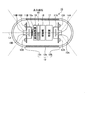
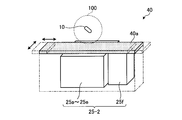
- FIG. 2 is a perspective view schematically showing the appearance of the guidance device 20.
- the guidance device 20 is provided with a bed 20a as a mounting table on which the subject is mounted.
- An induction magnetic field generation unit 25 that generates the magnetic field 100 is disposed at least below the bed 20a.
- the receiving unit 21 includes a plurality of antennas 21a, and sequentially receives radio signals from the capsule endoscope 10 via the plurality of antennas 21a.
- the receiving unit 21 selects the antenna having the highest received electric field strength from the plurality of antennas 21a, and performs a demodulation process or the like on the radio signal from the capsule endoscope 10 received via the selected antenna. Thereby, the receiving unit 21 extracts image data related to the inside of the subject from this wireless signal.
- the receiving unit 21 outputs an image signal including the extracted image data to the display unit 23.
- the position detection unit 22 performs a calculation for estimating the position of the capsule endoscope 10 in the subject based on the signal strength of the radio signal received by the reception unit 21.
- the display unit 23 includes various displays such as a liquid crystal display, and generates a screen including an in-vivo image based on the image data input from the receiving unit 21 and other various information and displays the screen on the display.
- the display unit 23 displays, for example, an in-vivo image group of the subject imaged by the capsule endoscope 10, and information on the position and posture of the capsule endoscope 10 and information on guidance operation. indicate.
- the display unit 23 may display the position and posture of the capsule endoscope 10 estimated from the magnetic field generated by the guidance device 20, or display based on the position detection result of the position detection unit 22.
- a position in the subject corresponding to the internal in-vivo image may be displayed on the screen.
- the display unit 23 displays, for example, a reduced image of the in-vivo image selected under the control of the control unit 26, patient information, examination information, and the like of the subject.
- the operation input unit 24 is realized by an input device such as a joystick, a console with various buttons and various switches, a keyboard, and the like, and provides guidance information for guiding the capsule endoscope 10 magnetically and the guidance device 20. And receiving various information such as setting information for setting a predetermined mode.
- the guidance instruction information is information for controlling the posture and position of the capsule endoscope 10 that is the object of the magnetic guidance operation. Specifically, the guidance instruction information includes an operation for changing the position of the capsule endoscope 10 and a capsule type.
- Information related to the operation of changing the tilt angle (angle with respect to the vertical axis) of the endoscope 10 and the azimuth angle (angle around the vertical axis) of the visual field (imaging units 11A and 11B described later) of the capsule endoscope 10 are changed.
- Information on the operation to be performed is included.
- the azimuth angle of the visual field is simply referred to as azimuth angle.
- the operation input unit 24 inputs the received information to the control unit 26.
- the guidance magnetic field generation unit 25 generates a magnetic field for changing the position, tilt angle, and azimuth angle of the capsule endoscope 10 introduced into the subject relative to the subject. More specifically, the induction magnetic field generation unit 25 includes an extracorporeal permanent magnet 25a as a magnetic field generation unit that generates a magnetic field, a first planar position changing unit 25b as a mechanism for translating and rotating the extracorporeal permanent magnet 25a, It has a position changing unit 25c, an elevation angle changing unit 25d, and a turning angle changing unit 25e.
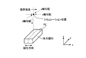
- FIG. 3 is a schematic diagram for explaining an installation state of the extracorporeal permanent magnet 25a.
- the extracorporeal permanent magnet 25a is realized by, for example, a bar magnet having a rectangular parallelepiped shape, and is one of four surfaces parallel to its magnetization direction (hereinafter also referred to as a capsule facing surface PL).
- the capsule endoscope 10 is constrained in a region opposite to.
- the extracorporeal permanent magnet 25a is arranged so that the capsule facing surface PL is parallel to the horizontal plane in the initial state.
- the arrangement of the extracorporeal permanent magnet 25a when the extracorporeal permanent magnet 25a is in the initial state is set as a reference arrangement, the magnetization direction at this time is the X axis direction, the direction in the horizontal plane perpendicular to the magnetization direction is the Y axis direction, and the vertical direction Is the Z-axis direction.
- the extracorporeal permanent magnet 25a has a length in the horizontal plane direction (Y-axis direction in FIG. 3) perpendicular to the magnetization direction among the lengths of the three directions of the rectangular parallelepiped shape. , X-axis direction) and a direction (Z direction in FIG. 3) perpendicular to the capsule facing surface PL.
- the extracorporeal permanent magnet 25a has a flat plate shape having the shortest length in the direction orthogonal to the capsule facing surface PL among the lengths of the three sides of the rectangular parallelepiped shape. The shape of the extracorporeal permanent magnet 25a will be described in detail later.
- the first plane position changing unit 25b is a translation mechanism that translates the extracorporeal permanent magnet 25a in a horizontal plane. That is, the movement is performed in the horizontal plane while the relative position of the two magnetic poles magnetized in the extracorporeal permanent magnet 25a is secured.
- the vertical position changing unit 25c is a translation mechanism that translates the extracorporeal permanent magnet 25a in the vertical direction.
- the elevation angle changing unit 25d is a rotating mechanism that rotates the permanent magnet in the vertical plane including the extracorporeal permanent magnet 25a to change the angle of the magnetization direction with respect to the horizontal plane.
- the elevation angle changing unit 25d preferably rotates the extracorporeal permanent magnet 25a with respect to an axis (hereinafter referred to as a rotation axis Y C ) parallel to the capsule facing surface PL and orthogonal to the magnetization direction and passing through the center of the extracorporeal permanent magnet 25a.
- an elevation angle ⁇ the angle between the extracorporeal permanent magnet 25a and the horizontal plane.
- the turning angle changing unit 25e rotates the extracorporeal permanent magnet 25a with respect to a vertical axis passing through the center of the extracorporeal permanent magnet 25a.
- the rotational movement of the extracorporeal permanent magnet 25a with respect to the vertical axis is referred to as a turning movement.
- an angle at which the extracorporeal permanent magnet 25a turns with respect to the reference arrangement is defined as a turning angle ⁇ .
- the control unit 26 controls the operation of each unit of the guidance magnetic field generation unit 25 based on the detection result of the position detection unit 22 and the guidance instruction information received by the operation input unit 24, so that the capsule endoscope 10 is moved to the user. Guide to the desired position and posture. At this time, the control unit 26 calculates the correction direction and the correction amount in order to correct the position change of the capsule endoscope 10 which is not intended by the user due to the rotation of the extracorporeal permanent magnet 25a, and the calculated correction direction and correction amount. Based on the above, the operation of the first plane position changing unit 25b is controlled.
- the storage unit 27 is realized by using a storage medium that stores information in a rewritable manner such as a flash memory or a hard disk.
- the storage unit 27 stores information such as various programs and various parameters for the control unit 26 to control each unit of the guidance device 20 in addition to the image data of the in-vivo image group of the subject imaged by the capsule endoscope 10. To do.
- FIG. 4 is a schematic cross-sectional view showing an example of the internal structure of the capsule endoscope 10.
- the capsule endoscope 10 captures images of subjects in different imaging directions from the capsule-type casing 12 that is an exterior formed in a size that can be easily introduced into the organ of a subject.
- Imaging units 11A and 11B that generate image information are provided.
- the capsule endoscope 10 includes a wireless communication unit 16 that wirelessly transmits image information generated by the imaging units 11A and 11B to the outside, and a control unit 17 that controls each component of the capsule endoscope 10.
- a power supply unit 18 that supplies power to each component of the capsule endoscope 10.
- the capsule endoscope 10 includes a permanent magnet 19 for enabling magnetic guidance by the guidance device 20.
- the capsule-type housing 12 is an outer case formed in a size that can be introduced into an organ of a subject, and is realized by closing both side opening ends of the cylindrical housing 12a with dome-shaped housings 12b and 12c.
- the dome-shaped casings 12b and 12c are dome-shaped optical members that are transparent to light of a predetermined wavelength band such as visible light.
- the cylindrical housing 12a is a colored housing that is substantially opaque to visible light.
- the capsule housing 12 formed by the cylindrical housing 12a and the dome-shaped housings 12b and 12c includes an imaging unit 11A, 11B, a wireless communication unit 16, a control unit 17, and a power supply unit. 18 and the permanent magnet 19 are enclosed in a liquid-tight manner.
- the imaging unit 11A includes an illumination unit 13A such as an LED, an optical system 14A such as a condenser lens, and an imaging element 15A such as a CMOS image sensor or a CCD.
- the illuminating unit 13A emits illumination light such as white light to the imaging field of the image sensor 15A, and illuminates the subject in the imaging field through the dome-shaped housing 12b.
- the optical system 14A condenses the reflected light from the imaging field of view on the imaging surface of the imaging element 15A to form a subject image in the imaging field of view.
- the imaging element 15A receives reflected light from the imaging field focused on the imaging surface, performs photoelectric conversion processing on the received optical signal, and obtains image information representing the subject image in the imaging field, that is, the in-vivo image of the subject. Generate.
- the imaging unit 11B includes an illumination unit 13B such as an LED, an optical system 14B such as a condenser lens, and an imaging element 15B such as a CMOS image sensor or a CCD.
- an illumination unit 13B such as an LED
- an optical system 14B such as a condenser lens
- an imaging element 15B such as a CMOS image sensor or a CCD.
- each of the imaging units 11A and 11B has an optical axis.
- the capsule housing 12 is arranged so as to be substantially parallel or substantially coincident with the long axis La, which is the central axis in the longitudinal direction of the capsule housing 12, and the imaging fields of view are directed in opposite directions. That is, the imaging units 11A and 11B are mounted so that the imaging surfaces of the imaging elements 15A and 15B are orthogonal to the long axis La.
- the wireless communication unit 16 includes an antenna 16a, and sequentially wirelessly transmits the image information acquired by the imaging units 11A and 11B described above to the outside via the antenna 16a. Specifically, the wireless communication unit 16 acquires an image signal based on the image information generated by the imaging unit 11A or the imaging unit 11B from the control unit 17, performs a modulation process on the image signal, and performs this image processing. A radio signal obtained by modulating the signal is generated. The wireless communication unit 16 transmits this wireless signal to the external receiving unit 21 via the antenna 16a.
- the control unit 17 controls each operation of the imaging units 11A and 11B and the wireless communication unit 16, and controls input / output of signals between these components. Specifically, the control unit 17 causes the imaging device 15A to image the subject in the imaging field illuminated by the illumination unit 13A, and causes the imaging device 15B to image the subject in the imaging field illuminated by the illumination unit 13B.
- the control unit 17 has a signal processing function for generating an image signal.
- the control unit 17 acquires image information from the image sensors 15A and 15B, and performs predetermined signal processing on the image information each time to generate an image signal including image data. Further, the control unit 17 controls the wireless communication unit 16 so as to sequentially wirelessly transmit such image signals to the outside along a time series.
- the power supply unit 18 is a power storage unit such as a button-type battery or a capacitor, and has a switch unit such as a magnetic switch or an optical switch.
- the power supply unit 18 switches the on / off state of the power supply by a magnetic field applied from the outside.
- the power of the power storage unit is transferred to each component of the capsule endoscope 10 (imaging units 11A and 11B, wireless communication unit 16 and the control unit 17). Further, the power supply unit 18 stops the power supply to each component of the capsule endoscope 10 when it is in the off state.
- the permanent magnet 19 is for enabling the magnetic guidance of the capsule endoscope 10 by the magnetic field 100 generated by the induction magnetic field generation unit 25, and the magnetization direction has an inclination with respect to the long axis La. It is fixedly arranged inside the capsule-type housing 12. Specifically, the permanent magnet 19 is arranged so that the magnetization direction is orthogonal to the long axis La. The permanent magnet 19 operates following a magnetic field applied from the outside. As a result, magnetic guidance of the capsule endoscope 10 by the guidance magnetic field generation unit 25 is realized.
- the permanent magnet 19 is fixedly arranged inside the capsule casing 12 in a state of being fixed relatively to the above-described imaging units 11A and 11B. More specifically, the permanent magnet 19 is arranged such that its magnetization direction is fixed relative to the vertical direction of the imaging surfaces of the imaging elements 15A and 15B. Specifically, as shown in FIG. 5, the permanent magnet 19 is arranged such that the magnetization direction Ym thereof is parallel to the vertical direction Yu of the imaging surfaces of the imaging elements 15A and 15B.
- FIG. 6 is a conceptual diagram for explaining the state of the capsule endoscope 10 with the liquid W introduced into the subject. 6 shows a state in which the magnetic field from the induction magnetic field generation unit 25 for controlling the position and posture of the capsule endoscope 10 is not acting on the permanent magnet 19 in the capsule endoscope 10. FIG. Yes.
- the capsule endoscope 10 illustrated in the first embodiment is designed to float in the liquid W.
- the center of gravity G of the capsule endoscope 10 is from the geometric center C of the capsule endoscope 10 to the long axis La of the capsule endoscope 10 (the central axis in the longitudinal direction of the capsule endoscope 10: (See FIG. 4).
- the center of gravity G of the capsule endoscope 10 is a position on the long axis La by adjusting the arrangement of the respective components such as the power supply unit 18 and the permanent magnet 19, and the capsule housing 12. Is set to a position deviated from the geometric center C of the image pickup unit 11B.
- the capsule endoscope 10 floats in the liquid W in a state where its long axis La is substantially parallel to the vertical direction (that is, the gravity direction). In other words, the capsule endoscope 10 floats in the liquid W in a state where a straight line connecting the geometric center C and the center of gravity G is upright. In such an upright posture, the capsule endoscope 10 directs the imaging field of the imaging unit 11A vertically upward and the imaging field of the imaging unit 11B vertically downward.
- the liquid W is a liquid that is harmless to the human body, such as water or physiological saline.
- the permanent magnet 19 is arranged so that the magnetization direction Ym (see FIG. 5) is orthogonal to the long axis La. That is, the magnetization direction Ym of the permanent magnet 19 coincides with the radial direction of the capsule endoscope 10. Therefore, when the magnetic field for controlling the position and posture of the capsule endoscope 10 is not acting on the permanent magnet 19, the capsule endoscope 10 is in a state where the magnetization direction Ym coincides with the horizontal direction. Drift inside. At this time, a plane passing through the magnetization direction Ym and a line connecting the geometric center C and the center of gravity G of the capsule housing 12 is a vertical plane.
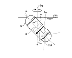
- FIG. 7 is a conceptual diagram for explaining the state of the capsule endoscope 10 with the liquid W introduced into the subject.
- a magnetic field for controlling the tilt angle of the capsule endoscope 10 is illustrated.
- the state which is made to act on the permanent magnet 19 is shown.
- the inclination of the long axis La of the capsule endoscope 10 with respect to the gravity direction Dg can be controlled by applying a magnetic field to the permanent magnet 19 of the capsule endoscope 10 from the outside.
- a magnetic field having the direction of the magnetic force line to the horizontal plane on the permanent magnet 19
- the capsule endoscope 10 is gravity-induced so that the magnetization direction Ym of the permanent magnet 19 is substantially parallel to the magnetic force line. It can be inclined with respect to the direction Dg.
- the orientation of the capsule endoscope 10 changes while maintaining the state in which the magnetization direction Ym is included in the vertical plane.
- the magnetic field for performing such control is realized by changing the elevation angle ⁇ of the extracorporeal permanent magnet 25a by the elevation angle changing unit 25d of the guidance device 20 (see FIGS. 1 and 3).
- the capsule endoscope 10 is turned around the gravity direction Dg as shown by an arrow by applying a magnetic field that turns around the gravity direction Dg while the capsule endoscope 10 is tilted.
- An in-vivo image around the mold endoscope 10 can be easily acquired.
- the magnetic field for performing such control is realized by turning the extracorporeal permanent magnet 25a by the turning angle changing unit 25e of the guidance device 20 (see FIGS. 1 and 3).
- the display unit 23 of the guidance device 20 displays the capsule endoscope in a display mode in which the vertical direction of the subject in the in-vivo image accompanying the magnetic guidance of the capsule endoscope 10 matches the vertical direction of the display screen. 10 shows the in-vivo image of the subject.
- the liquid level Ws imaged by the element in the upper region Pu of the imaging device 15A of the capsule endoscope 10 corresponds to the imaging unit 11A. Displayed at the top of the image.
- the direction parallel to the magnetization direction Ym of the permanent magnet 19 is on the display screen of the display unit 23. It coincides with the vertical direction.
- the translational movement in the horizontal direction of the capsule endoscope 10 causes a magnetic field (see FIG. 9A) having a magnetic field strength peak in the capsule facing surface PL to be applied to the capsule endoscope 10. It can be controlled by acting on the permanent magnet 19 and attracting the permanent magnet 19 to the peak position of the magnetic field to restrain the capsule endoscope 10 (see FIG. 9B). Specifically, such a magnetic field is realized by moving the extracorporeal permanent magnet 25a in the horizontal plane by the first plane position changing unit 25b of the guidance device 20.
- the translational motion in the vertical direction of the capsule endoscope 10 causes the magnetic field of the capsule endoscope 10 to change according to the distance in the direction perpendicular to the capsule facing surface PL. It can be controlled by acting on the permanent magnet 19. Specifically, such a magnetic field is realized by moving the extracorporeal permanent magnet 25 a in the vertical direction by the vertical position changing unit 25 c of the guidance device 20.
- FIG. 10A when the capsule facing surface PL is made horizontal, a magnetic field whose magnetic gradient becomes weaker as the vertical position becomes higher is applied to the permanent magnet 19.
- FIG. 10B when the extracorporeal permanent magnet 25a is moved upward to relatively lower the vertical position of the permanent magnet 19, the magnetic attractive force applied to the permanent magnet 19 becomes stronger, and the capsule The mold endoscope 10 is biased downward.
- the position of the capsule endoscope 10 in the vertical direction is determined by the buoyancy of the capsule endoscope 10 with respect to the liquid W, the gravity applied to the capsule endoscope 10, and the magnetic attractive force applied by the extracorporeal permanent magnet 25a. It is almost maintained at a balanced position.
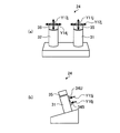
- FIG. 11A is a front view of the operation input unit 24, and FIG. 11B is a right side view of the operation input unit 24.
- FIG. 12 is a diagram illustrating the movement of the capsule endoscope 10 instructed by the operation of each component of the operation input unit 24.
- the operation input unit 24 includes two joysticks 31 and 32 for three-dimensionally operating the magnetic guidance of the capsule endoscope 10 by the guidance magnetic field generation unit 25.
- the joysticks 31 and 32 can be tilted in the vertical direction and the horizontal direction.
- an up button 34U and a down button 34B are provided on the back of the joystick 31.
- guidance instruction information that instructs the capsule endoscope 10 to be guided upward is input to the control unit 26, and when the down button 34B is pressed, the capsule endoscope 10 is moved.
- Guidance instruction information for instructing downward guidance is input to the control unit 26.
- a capture button 35 is provided on the joystick 31. When the capture button 35 is pressed, the in-vivo image displayed on the display unit 23 is captured.
- an approach button 36 is provided on the upper part of the joystick 32. When the approach button 36 is pressed, it controls guidance instruction information for guiding the capsule endoscope 10 to bring the imaging unit 11A side of the capsule endoscope 10 closer to the imaging target of the imaging unit 11A. Input to the unit 26.
- the vertical tilt direction of the joystick 31 indicated by the arrow Y11j is such that the tip of the capsule endoscope 10 passes through the vertical axis Az as indicated by the arrow Y11 in FIG. Corresponds to the tilting guidance direction to shake.
- the control unit 26 moves in the tilt direction of the joystick 31 based on the guidance instruction information. Accordingly, the guide direction on the absolute coordinate system of the tip of the capsule endoscope 10 is calculated, and the guide amount is calculated according to the tilting operation of the joystick 31.
- generation part 25 controls the elevation angle change part 25d so that the elevation angle (theta) of the extracorporeal permanent magnet 25a may be changed according to the calculated induction
- the horizontal tilt direction indicated by the arrow Y12j of the joystick 31 is the rotation guiding direction in which the capsule endoscope 10 rotates about the vertical axis Az as indicated by the arrow Y12 in FIG.
- the control unit 26 moves the joystick 31 in the tilting direction based on the guidance instruction information. Accordingly, the guidance direction on the absolute coordinate system of the tip of the capsule endoscope 10 is calculated, the guidance amount is calculated according to the tilting operation of the joystick 31, and further, for example, the calculated guidance amount is calculated in the calculated guidance direction. Accordingly, the turning angle changing unit 25e is controlled to turn the extracorporeal permanent magnet 25a.
- the vertical tilt direction indicated by the arrow Y13j of the joystick 32 is the direction in which the major axis La of the capsule endoscope 10 is projected onto the horizontal plane Hp as indicated by the arrow Y13 in FIG. Corresponds to the forward backward guidance direction or the horizontal forward guidance direction.
- guidance instruction information corresponding to the tilting operation of the arrow Y13j of the joystick 32 is input from the operation input unit 24 to the control unit 26, the control unit 26 moves the joystick 32 in the tilting direction based on the guidance instruction information.
- the first planar position changing unit calculates the guidance direction and the guidance amount on the absolute coordinate system of the tip of the capsule endoscope 10 and translates the extracorporeal permanent magnet 25a in accordance with the computed guidance direction and guidance quantity. 25b is controlled.
- the horizontal tilt direction indicated by the arrow Y14j of the joystick 32 is such that the capsule endoscope 10 is in the horizontal plane Hp and the long axis La is in the horizontal plane Hp as indicated by the arrow Y14 in FIG. Corresponds to a horizontal light guiding direction or a horizontal left guiding direction that runs perpendicular to the projected direction.
- the control unit 26 moves the joystick 32 in the tilting direction based on the guidance instruction information.
- the first planar position changing unit calculates the guidance direction and the guidance amount on the absolute coordinate system of the tip of the capsule endoscope 10 and translates the extracorporeal permanent magnet 25a in accordance with the computed guidance direction and guidance quantity. 25b is controlled.
- an up button 34U and a down button 34B are provided on the back of the joystick 32.
- an up operation is designated that proceeds upward as indicated by an arrow Y15 along the vertical axis Az shown in FIG.
- an arrow Y16j in FIG. 11B when the down button 34B is pressed, a down operation is instructed to proceed downward as shown by an arrow Y16 along the vertical axis Az shown in FIG. .
- the control unit 26 uses the guidance instruction information.
- the guidance direction and the guidance amount on the absolute coordinate system of the tip of the capsule endoscope 10 are calculated according to the pressed button, and the extracorporeal permanent magnet 25a is translated in the vertical direction according to the calculated guidance direction and the guidance amount.
- the vertical position changing unit 25c is controlled so as to make it. For example, when the up button 34U is pressed, the vertical position changing unit 25c translates the extracorporeal permanent magnet 25a downward in the vertical axis Az (in a direction away from the capsule endoscope 10).
- the capsule endoscope 10 is raised as indicated by an arrow Y15.
- the vertical position changing unit 25c translates the extracorporeal permanent magnet 25a in the upward direction of the vertical axis Az (direction approaching the capsule endoscope 10).
- the capsule endoscope 10 is lowered as indicated by an arrow Y16.
- the operation input unit 24 may further include an input device including various operation buttons, a keyboard, and the like in addition to the joysticks 31 and 32.
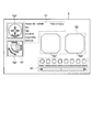
- FIG. 13 is a schematic diagram showing a display example of the menu screen S displayed on the display unit 23.
- each subject information such as the patient name, patient ID, date of birth, sex, age, etc. of the subject is displayed in the upper left region S1, and in the central region S2, the imaging unit 11A is displayed.
- the captured biological image Sg1 is displayed on the left side
- the biological image Sg2 captured by 11B is displayed on the right side
- each image captured by the pressing operation of the capture button 35 is captured in the region S3 below the region S2.
- the left side region S4 displays a posture diagram Sg3 in the vertical plane and a posture diagram Sg4 in the horizontal plane as posture diagrams of the capsule endoscope 10.
- the posture of the capsule endoscope 10 displayed in the posture diagrams Sg3 and Sg4 is a posture corresponding to the guidance instruction information of the operation input unit 24.
- the displayed posture of the capsule endoscope 10 is almost the same as the actual posture of the capsule endoscope 10. It can be considered the same, and the guidance instruction assistance for the operator is also improved.
- directions in which the capsule endoscope 10 can be guided are indicated by arrows, and when there is an operation input in any one of the guidance directions, it corresponds to the input direction. The display color of the arrow is changed to assist the operator's operation.
- the control unit 26 changes the amount of change caused by the rotation of the extracorporeal permanent magnet 25a. Control is performed to move the capsule endoscope 10 in a direction (correction direction) opposite to the direction of position change of the capsule endoscope 10 by an amount corresponding to (correction amount). Thereby, the change in the restraint position of the capsule endoscope 10 is canceled.
- the correction direction is the opposite direction of the rotation direction of the extracorporeal permanent magnet 25a by the elevation angle changing unit 25d on the axis where the vertical plane including the magnetization direction of the extracorporeal permanent magnet 25a intersects the horizontal plane.
- the correction amount D n is distributed to the correction amount in the X-axis direction and the correction amount in the Y-axis direction according to the turning angle ⁇ of the extracorporeal permanent magnet 25a that gives the azimuth angle of the capsule endoscope 10. .
- the control unit 26 acquires the position in the vertical direction of the capsule endoscope 10 (corresponding to the distances H 1 and H 2 shown in FIG. 14) from the detection result output from the position detection unit 22. To do. Further, the control unit 26 uses the guidance instruction information input from the operation input unit 24, and the extracorporeal permanent magnet 25a necessary for realizing the change and movement of the azimuth angle and inclination angle of the capsule endoscope 10 desired by the user. , Turning angle ⁇ , elevation angle ⁇ , translation direction, and translation amount.
- the correction amount is calculated using the elevation angle (theta).
- the calculation formula used at this time is stored in the storage unit 27 in advance.
- the control unit 26 corrects the translation direction and the translation amount of the extracorporeal permanent magnet 25a based on the guidance instruction information using the calculated correction direction and correction amount. Then, the control unit 26 changes the rotation and rotation of the extracorporeal permanent magnet 25a with the calculated turning angle ⁇ and elevation angle ⁇ , and generates an induced magnetic field so as to translate the extracorporeal permanent magnet 25a with the corrected translation direction and translation amount.
- Each part of the part 25 is controlled.
- control unit 26 does not calculate the correction direction and the correction amount but corrects the rotation angle ⁇ and the elevation angle ⁇ of the extracorporeal permanent magnet 25a and the position of the capsule endoscope 10 in the vertical direction.
- the direction and the correction amount are stored in the storage unit 27 in advance, and when the guidance instruction information for rotating the capsule endoscope 10 is input from the operation input unit 24, the input guidance instruction information and the detection of the position detection unit 22 are performed.
- a necessary correction direction and correction amount may be extracted from the storage unit 27 based on the result (the position of the capsule endoscope 10 in the vertical direction).
- control unit 26 makes the extracorporeal permanent in accordance with the translation amount so that the movement of the capsule endoscope 10 is completed within a predetermined time. Control for adjusting the translation speed of the magnet 25a may be performed.
- FIG. 15 is a schematic diagram for explaining evaluation items in this simulation. As shown in FIG. 15, in this simulation, the magnetization direction of the permanent magnet is the x-axis direction, the direction orthogonal to the magnetization direction of the surface PL ′ facing the simulation position is the y-axis direction, and the direction orthogonal to the surface PL ′.
- the magnetic strength is involved in guidance when changing the azimuth angle and the tilt angle with respect to the capsule endoscope 10.
- the magnetic gradient in the z-axis direction is involved in guidance in the z-axis direction with respect to the capsule endoscope 10.
- the magnetic gradient in the x-axis direction is involved in guidance in the x-axis direction with respect to the capsule endoscope 10.
- the magnetic gradient in the y-axis direction is involved in guidance in the y-axis direction with respect to the capsule endoscope 10.
- FIG. 16 is a table showing the ratio of the lengths of the sides of the permanent magnet used in the simulation.
- the “length in the x-axis direction” shown in FIG. 16 corresponds to the length of the side parallel to the x-axis
- the “length in the y-axis direction” corresponds to the length of the side parallel to the y-axis.
- “Axial length” corresponds to the length of the side parallel to the z-axis.
- long sides of the sides of each permanent magnet are shown in order from the left.
- the type “xyz” indicates a rectangular parallelepiped shape having the longest side parallel to the x-axis and the shortest side parallel to the z-axis. Note that the type “xyz” indicates a cube in which all sides have the same length.
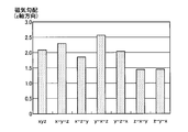
- FIG. 17 is a graph showing the magnetic field strength of each permanent magnet shown in FIG.
- FIG. 18 is a graph showing the magnetic gradient in the z-axis direction generated by each permanent magnet shown in FIG.
- FIG. 19 is a graph showing a magnetic gradient in the x-axis direction generated by each permanent magnet shown in FIG.
- FIG. 20 is a graph showing a magnetic gradient in the y-axis direction generated by each permanent magnet shown in FIG.
- the value of the magnetic field strength is normalized.
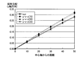
- the magnetic gradient values are normalized through FIGS. 19 and 20, the horizontal axis indicates a value obtained by normalizing the distance from the axis (center axis) in the z-axis direction passing through the center of the permanent magnet.
- the magnetic field intensity generated by the permanent magnet is strong.
- the magnets that obtained a relatively large magnetic field strength were the type yz and the type xy. Therefore, it can be seen that the shape suitable for controlling the azimuth angle and the tilt angle of the capsule endoscope 10 is a shape in which the length in the z-axis direction is shorter than the length in the y-axis direction. Furthermore, it can be said that a flat shape in which the length in the z-axis direction is shorter than the length in the x-axis direction and the y-axis direction is more preferable.
- the projected area on the zx plane orthogonal to the y axis is small because the moving area of the permanent magnet during rotation can be reduced. . Therefore, it is better to shorten the length in the x-axis direction.
- the permanent magnet can be installed closer to the subject, a high-intensity magnetic field can be efficiently generated in the subject, and the induction magnetic field generation unit 25 can be reduced in size.
- the magnetic gradient in the vertical direction is large.
- the magnets that obtained a relatively large magnetic gradient in the z-axis direction were the type yz and the type xy. Therefore, it can be seen that the shape suitable for the position control in the vertical direction of the capsule endoscope 10 is a flat shape with a short length in the z-axis direction.
- the magnetic gradient in the horizontal direction is large.
- the magnets that obtained a relatively large magnetic gradient in the x-axis direction were of type yz and type yzx.
- the magnets having a relatively large magnetic gradient in the y-axis direction were of type yxz and type xyz.
- the shape suitable for the horizontal control of the capsule endoscope 10 is a shape having a longer length in the y-axis direction than in the x-axis direction and the z-axis direction. Further, it can be said that the length in the x-axis direction is preferably not so long as compared with the y-axis direction and the z-axis direction.
- the shape of the extracorporeal permanent magnet 25a suitable for controlling the capsule endoscope 10 is a flat plate having the longest length in the y-axis direction and the shortest length in the z-axis direction. all right. Therefore, the inventors subsequently performed another simulation for obtaining a suitable ratio of the lengths of the sides of the extracorporeal permanent magnet 25a.
- FIG. 21 is a table showing the ratio of the lengths of the sides of the permanent magnet used in another simulation.
- the “length in the x-axis direction” shown in FIG. 21 corresponds to the length of the side parallel to the x-axis
- the “length in the y-axis direction” corresponds to the length of the side parallel to the y-axis.
- “Axial length” corresponds to the length of the side parallel to the z-axis.
- the longer ones of the sides of each permanent magnet are shown in order from the left, and the numerical values in parentheses are the values in the z-axis direction with respect to the length in the x-axis direction.
- the ratio of length is shown.
- a cuboid permanent magnet having the longest side parallel to the y-axis direction and the shortest side parallel to the z-axis direction is used.
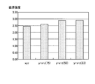
- FIG. 22 is a graph showing the magnetic field strength of each permanent magnet shown in FIG.
- FIG. 23 is a graph showing the magnetic gradient in the z-axis direction generated by each permanent magnet shown in FIG.
- FIG. 24 is a graph showing the magnetic gradient in the x-axis direction generated by each permanent magnet shown in FIG.
- FIG. 25 is a graph showing a magnetic gradient in the y-axis direction generated by each permanent magnet shown in FIG.
- the value of the magnetic field strength is normalized.
- the magnetic gradient values are normalized through FIGS. 24 and 25, the horizontal axis indicates a value obtained by normalizing the distance from the axis (center axis) in the z-axis direction passing through the center of the permanent magnet.
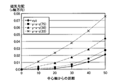
- FIG. 26 shows the ratio of the length in the y-axis direction to the length in the z-axis direction (the ratio of the length), and the permanent magnet having the above-described ratios to the magnetic field strength of the permanent magnet of type yxz (33). It is a graph which shows the relationship with the ratio of the magnetic field intensity of. As shown in FIG. 26, when the length in the y-axis direction is 1.5 times the length in the z-axis direction, the permanent magnet of type yxz (33), that is, the length in the z-axis direction A magnetic field strength of about 90% can be generated with respect to the magnetic field strength generated by a permanent magnet having a sufficiently long length in the y-axis direction.
- the length in the y-axis direction with respect to the length in the z-axis direction is three times or more, the ratio of the magnetic field strength becomes 95%. Therefore, as a preferable shape of the permanent magnet, the length in the y-axis direction with respect to the length in the z-axis direction is preferably 1.5 times or more or 3 times or more.
- the change in the restraint position of the capsule endoscope 10 caused by the rotation of the extracorporeal permanent magnet 25a is controlled under the control of the control unit 26. Since it correct
- the capsule endoscope 10 since the capsule endoscope 10 is guided in a state where the capsule endoscope 10 is floated on the liquid into which the liquid is introduced into the subject, the capsule endoscope 10 is guided.
- the induction magnetic field generating unit 25 for doing so can be disposed below the bed 20a on which the subject is placed, and the entire guidance device 20 can be downsized.
- a compound eye capsule in which the imaging units 11A and 11B are provided at both ends of the capsule endoscope 10 is used.
- an imaging unit is provided at one end of the capsule endoscope.
- a provided monocular capsule may be used.
- the capsule endoscope that captures only an image below the water surface (underwater) can be realized by bringing the center of gravity G of the capsule endoscope closer to the end on the side where the imaging unit is not provided.
- the permanent magnet 19 is arranged so that the magnetization direction is orthogonal to the long axis La of the capsule endoscope 10, but the magnetization direction matches the direction of the long axis La.
- the permanent magnet 19 may be arranged as described above.
- the center of gravity G may be installed at a position shifted in the radial direction with respect to the geometric center C of the capsule endoscope 10. In this case, the posture of the capsule endoscope 10 can be uniquely controlled in the liquid W.
- the center of gravity G when the magnetic field is not applied, the center of gravity G is placed on the long axis La so that the capsule endoscope 10 floats with the long axis La oriented in the vertical direction.
- the position of the center of gravity G may be set to be shifted from the long axis La so that the capsule endoscope 10 floats with the long axis La inclined with respect to the vertical direction without applying a magnetic field.
- the azimuth angle and tilt angle of the capsule endoscope 10 in the liquid W can be uniquely controlled.
- the center of gravity G of the capsule endoscope may be set so as to be shifted from the geometric center C in a direction different from the magnetization direction of the permanent magnet 19. Also in this case, the azimuth angle and tilt angle of the capsule endoscope 10 in the liquid W can be uniquely controlled.
- an electromagnet that generates a magnetic field similar to the above-described external permanent magnet 25a may be used.
- the extracorporeal permanent magnet 25a has a rectangular parallelepiped shape.
- the length in the horizontal direction perpendicular to the magnetization direction of the extracorporeal permanent magnet 25a is longer than the length in the magnetization direction and the length in the direction perpendicular to the magnetization direction and the horizontal direction perpendicular to the magnetization direction. If it has, you may make it a shape other than a rectangular parallelepiped.
- the extracorporeal permanent magnet 25a may have a shape in which the length in the direction perpendicular to the magnetization direction and the horizontal direction perpendicular to the magnetization direction is the shortest of the three directions. In this case, a strong magnetic field can be generated.
- the magnetization direction and the lengths in the first and second directions may be defined by the diameter, the length of the long axis, or the length of the short axis.
- the control unit 26 indicates that the position detection unit 22 indicates the correction direction and the correction amount necessary for correcting the change in the restraint position of the capsule endoscope 10 due to the rotation of the extracorporeal permanent magnet 25a. Calculation was made based on the detected vertical position of the capsule endoscope 10 and the turning angle ⁇ and the elevation angle ⁇ of the extracorporeal permanent magnet 25a based on the guidance instruction information, or extracted from values stored in the storage unit 27 in advance. However, the control unit 26 may acquire the correction direction and the correction amount based only on the guidance instruction information.
- the correction direction and the correction amount corresponding to the turning angle ⁇ and the elevation angle ⁇ of the internal permanent magnet 25a are stored in the storage unit 27 in advance.
- the correction direction and correction amount stored in the storage unit 27 are representative values calculated in advance for each turning angle ⁇ and elevation angle ⁇ (for example, the average of correction amounts corresponding to the vertical positions of the capsule endoscope 10). Value and maximum value).
- the control unit 26 calculates the turning angle ⁇ , the elevation angle ⁇ , the translation direction, and the translation amount of the extracorporeal permanent magnet 25a based on the guidance instruction information. Then, the correction direction and the correction amount are extracted from the storage unit 27 based on the calculated turning angle ⁇ and the elevation angle ⁇ , and the translation direction and the translation amount based on the guidance instruction information are corrected using the extracted correction direction and correction amount. . Further, the control unit 26 controls each unit of the induced magnetic field generation unit 25 so as to rotate and translate the extracorporeal permanent magnet 25a with the turning angle ⁇ and the elevation angle ⁇ based on the guidance instruction information, and the corrected translation direction and translation amount. To do.
- the correction direction and the correction amount are obtained without using the detection result of the position detection unit 22, so that the induction magnetic field generation unit 25 can be controlled at high speed.
- Modification 1-2 is characterized in that the vertical position H of the capsule endoscope 10 used for calculation of the correction amount is manually set in a stepwise manner.
- the display unit 23 displays, on the screen, a plurality of options representing the vertical position H of the capsule endoscope 10 under the control of the control unit 26.
- the operation input unit 24 receives an input of a selection signal for selecting one of a plurality of options by a user operation, and inputs the selection signal to the control unit 26.
- the control unit 26 sets the vertical position H corresponding to the input selection signal as the current vertical position of the capsule endoscope 10.
- the storage unit 27 stores in advance the correction direction and the correction amount corresponding to the turning angle ⁇ , the vertical position H, and the elevation angle ⁇ of the internal permanent magnet 25a.
- the control unit 26 acquires the turning angle ⁇ , the elevation angle ⁇ , the translation direction, and the translation amount for controlling the extracorporeal permanent magnet 25a based on the guidance instruction information. To do. Then, based on the acquired turning angle ⁇ and elevation angle ⁇ and the currently set vertical position H of the capsule endoscope 10, the correction direction and the correction amount are extracted from the storage unit 27. Further, the control unit 26 corrects the translation direction and the translation amount based on the guidance instruction information using the extracted correction direction and correction amount, and makes the extracorporeal permanent with the turning angle ⁇ , the elevation angle ⁇ , the corrected correction direction and the correction amount. Each part of the induction magnetic field generation unit 25 is controlled to rotate and translate the magnet 25a.
- the correction direction and the correction amount are acquired using the vertical position of the capsule endoscope 10 set in stages, so that the induction magnetic field generation unit 25 can be controlled at high speed. And the correction accuracy can be improved.
- the guidance device 20 may be provided with at least two guidance modes for guiding the capsule endoscope 10 and selectable by the user.
- the display unit 23 displays a plurality of options representing the guidance mode of the capsule endoscope 10 on the screen under the control of the control unit 26.
- Examples of the guide mode that can be selected by the user include the following (a) to (c).
- the operation input unit 24 receives an input of a selection signal for selecting one of a plurality of options by a user operation and inputs it to the control unit 26.
- the control unit 26 sets the guidance mode corresponding to the input selection signal as the current guidance mode, and controls the guidance magnetic field generation unit 25 to guide the capsule endoscope 10 in the set guidance mode.
- the control unit 26 calculates the turning angle ⁇ , the elevation angle ⁇ , the translation direction, and the translation amount for controlling the extracorporeal permanent magnet 25a, and the calculated turning angle.
- the correction direction and the correction amount are acquired according to ⁇ , the elevation angle ⁇ , and the current guidance mode (see Embodiment 1 and Modifications 1-1 to 1-3).
- the control unit 26 acquires the correction direction and the correction amount in consideration of the state of the capsule endoscope 10 or adjusts the acquired correction direction and correction amount.
- Modification 1-4 of Embodiment 1 will be described.
- the control unit 26 based on the guidance instruction information input from the operation input unit 24, the azimuth angle and inclination angle of the capsule endoscope 10 desired by the user (the inclination of the long axis La) And information on the target position (the coordinates in the XYZ axis directions).
- the extracorporeal permanent magnet 25a is rotated (the turning angle ⁇ and the elevation angle ⁇ are changed) to change the field of view of the capsule endoscope 10, and based on the position detection result output from the position detection unit 22 at any time, the capsule Feedback control is performed so that the position of the mold endoscope 10 matches the target position.
- FIG. 27A is a front view of the operation input unit 24 according to Modification 1-5
- FIG. 27B is a right side view of the operation input unit 24, and
- FIG. It is a figure which shows the other example of the operation
- each operation of the operation input unit 24 and the guidance operation of the capsule endoscope 10 are not performed along the plane orthogonal to the long axis La of the capsule endoscope 10 instead of the horizontal plane Hp.
- the endoscope 10 may be associated so that it can be guided.
- the movement of the capsule endoscope 10 corresponding to the guiding operation when the capsule endoscope 10 is guided along a plane orthogonal to the long axis La of the capsule endoscope 10 will be described.
- the vertical tilt direction indicated by the arrow Y23j of the joystick 32 is such that the capsule endoscope 10 has a plane perpendicular to the long axis La as indicated by the arrow Y23, as shown in FIG. A down guidance direction or an up guidance direction proceeding to is indicated.
- operation information corresponding to the tilting operation of the arrow Y23j of the joystick 32 is input from the operation input unit 24 to the control unit 26, the induced magnetic field generation unit 25 moves in the tilting direction of the joystick 32 based on this operation information.
- the guidance direction and the guidance amount on the absolute coordinate system of the distal end of the capsule endoscope 10 are calculated, and the first planar position changing unit 25b is translated so as to translate the extracorporeal permanent magnet 25a according to the calculated guidance direction and guidance amount. And the vertical position change part 25c is controlled.
- the horizontal tilt direction indicated by the arrow Y24j of the joystick 32 is such that the capsule endoscope 10 has a plane perpendicular to the long axis La as indicated by the arrow Y24, as shown in FIG. A right guidance direction or a left guidance direction to go to is designated.
- operation information corresponding to the tilting operation of the arrow Y24j of the joystick 32 is input from the operation input unit 24 to the control unit 26, the control unit 26 responds to the tilting direction of the joystick 32 based on the operation information.
- the first planar position changing unit 25b is controlled so that the guidance direction and the guidance amount on the absolute coordinate system of the distal end of the capsule endoscope 10 are calculated, and the extracorporeal permanent magnet 25a is translated according to the calculated guidance direction and guidance amount. To do.
- the guidance direction and the guidance amount on the absolute coordinate system of the distal end of the capsule endoscope 10 are calculated, and the first extracorporeal permanent magnet 25a is translated according to the calculated guidance direction and the calculation amount.
- the plane position changing unit 25b and the vertical position changing unit 25c are controlled.
- the vertical tilt direction of the joystick 31 indicated by the arrow Y21j is such that the tip of the capsule endoscope 10 passes through the vertical axis Az as indicated by the arrow Y21 in FIG.
- the tilting direction of the joystick 31 in the left-right direction indicated by the arrow Y22j is the rotation guidance in which the capsule endoscope 10 rotates about the vertical axis Az as indicated by the arrow Y22 in FIG. Corresponds to the direction.
- Modification 1-6 of Embodiment 1 will be described.
- the position detection of the capsule endoscope 10 in the subject may be performed by various methods other than the method based on the strength of the radio signal received from the capsule endoscope 10 described in the first embodiment. good.
- a method of detecting the position of the capsule endoscope 10 based on the acceleration applied to the capsule endoscope 10 may be used.
- an acceleration sensor that three-dimensionally detects the acceleration applied to the capsule endoscope 10 is provided inside the capsule endoscope 10, and the detection result of the acceleration sensor is superimposed on a radio signal and transmitted as needed.
- the guidance device 20 integrates the acceleration applied to the capsule endoscope 10 based on the detection result of the acceleration sensor superimposed on the received radio signal, and the relative change amount of the position of the capsule endoscope 10 is calculated. And the current position of the capsule endoscope 10 is calculated from the amount of change.
- Modification 1-7 of Embodiment 1 will be described.
- a method for detecting the position of the capsule endoscope 10 in the subject a method for detecting an alternating magnetic field may be used.
- an AC magnetic field generator that generates an AC magnetic field is provided inside the capsule endoscope 10.
- a plurality of magnetic field sensors for detecting an alternating magnetic field are provided on the induction device 20 side.
- the guiding device 20 detects the AC magnetic field generated by the capsule endoscope 10 by a plurality of magnetic field sensors installed at a plurality of locations, and based on the detection results, the position and position of the capsule endoscope 10 are detected.
- the direction can be calculated continuously.
- Modification 1-8 of Embodiment 1 will be described.
- a method for detecting the position of the capsule endoscope 10 in the subject another method for detecting an alternating magnetic field will be described.
- an LC circuit that resonates by an alternating magnetic field is provided inside the capsule endoscope 10.
- a plurality of magnetic field sensors for detecting an alternating magnetic field are provided on the induction device 20 side.
- the guidance device 20 generates an LC circuit in the capsule endoscope 10 when the capsule endoscope 10 is not located in the measurement region of the subject (the magnetic field region generated by the guiding magnetic field generation unit 25).
- the first resonance magnetic field to be detected is detected in advance.
- the second resonance magnetic field generated by the LC circuit in the capsule endoscope 10 is detected, and the first resonance magnetic field is detected.
- a difference value between the detected value of the second resonance magnetic field and the detected value of the second resonance magnetic field are continuously obtained. Further, based on these difference values, the position coordinates of the capsule endoscope 10 in the three-dimensional space are continuously calculated.
- FIG. 29 is a diagram illustrating a configuration example of a capsule medical device magnetic guidance system according to the second embodiment.
- the capsule medical device magnetic guidance system 2 according to the second embodiment includes a guidance device 40 having a guidance magnetic field generation unit 25-2 instead of the guidance device 20 shown in FIG.
- the induced magnetic field generating unit 25-2 further includes a second plane position changing unit 25f with respect to the induced magnetic field generating unit 25 shown in FIG.
- the configuration other than the second planar position changing unit 25f in the capsule medical device magnetic guidance system 2 is the same as that described in the first embodiment.
- FIG. 30 is a perspective view schematically showing the appearance of the guidance device 40.
- the guiding device 40 is provided with a bed 40a that can be translated in the horizontal direction as a mounting table on which the subject is mounted.
- An induction magnetic field generation unit 25-2 that generates the magnetic field 100 is disposed below the bed 40a.
- the second plane position changing unit 25f is a translation mechanism that translates the bed 40a in the horizontal direction.
- the second plane position changing unit 25f moves the bed 40a with the subject placed thereon, whereby the subject position relative to the capsule endoscope 10 constrained by the magnetic field 100 generated by the extracorporeal permanent magnet 25a, in other words, The relative position of the capsule endoscope 10 with respect to the subject is changed.
- the control unit 26 When the guidance instruction information for translating the capsule endoscope 10 is input from the operation input unit 24, the control unit 26 translates the bed 40a by the second plane position changing unit 25f based on the input guidance instruction information. The position of the capsule endoscope 10 relative to the subject is moved relatively.
- the control unit 26 determines the turning angle ⁇ of the extracorporeal permanent magnet 25a based on the input guidance instruction information.
- the elevation angle ⁇ is calculated, and the correction direction and the correction amount for correcting the change in the restraint position of the capsule endoscope 10 due to the rotation of the extracorporeal permanent magnet 25a are calculated.
- the extracorporeal permanent magnet 25a is translated with respect to the first plane position changing unit 25b based on the calculated correction direction and correction amount.
- the user grasps the change in the restraint position of the capsule endoscope 10 that occurs when the tilt angle of the capsule endoscope 10 is changed, and the correction direction and correction amount for correcting this change. I can't. Therefore, the correction operation that cannot be grasped by the user is realized by translation of the extracorporeal permanent magnet 25a installed at the lower part of the bed 40a, and the translation of the capsule endoscope 10 by the user's own operation is relative to the bed 40a. It is realized by dynamic movement. In this case, since the user can predict the movement of the bed 40a, the capsule endoscopy can be performed without a sense of incongruity. Further, since the extracorporeal permanent magnet 25a can be translated at a higher speed than the bed 40a on which the subject is placed, the inductivity of the capsule endoscope 10 can be improved.
- the translation of the capsule endoscope 10 in the horizontal direction is realized by the translation of the extracorporeal permanent magnet 25a and the translation of the bed 40a, and therefore the translation amount of the extracorporeal permanent magnet 25a. Therefore, it is possible to suppress an increase in the size of the entire guiding device 40.
- the translation of the capsule endoscope 10 based on the user's operation is realized by the translational movement of the bed 40a, and the correction of the capsule endoscope 10 that is not conscious of the user is performed by the extracorporeal permanent magnet 25a. Therefore, the user operability can be improved.
- Modification 2-1 Next, Modification 2-1 of Embodiment 2 will be described.
- the translational motion for correcting the restraint position of the capsule endoscope 10 and the translational motion of the capsule endoscope 10 based on the guidance instruction information are applied to the extracorporeal permanent magnet 25a and the bed 40a. Each was assigned. However, the total translational movement of the capsule endoscope 10 may be distributed to the extracorporeal permanent magnet 25a and the bed 40a at a predetermined ratio.
- the control unit 26 determines the turning angle ⁇ , the elevation angle ⁇ , the translation direction, and the translation amount for controlling the extracorporeal permanent magnet 25a based on the guidance instruction information. get. Further, in the same manner as in the first embodiment and its modifications 1-1 to 1-3, the correction direction and the correction amount for correcting the change in the restraint position of the capsule endoscope 10 due to the rotation of the extracorporeal permanent magnet 25a. To get. And the control part 26 correct
- This ratio is not particularly limited, and may be equally distributed between the extracorporeal permanent magnet 25a and the bed 40a, or may be given priority to translation by the extracorporeal permanent magnet 25a, or may be given priority to translation by the bed 40a. May be.
- the translation speeds of the extracorporeal permanent magnet 25a and the bed 40a are respectively set according to the translation amounts of the extracorporeal permanent magnet 25a and the bed 40a so that the movement of the capsule endoscope 10 is completed within a predetermined time. You may adjust it.
- the size of the guiding device 40 can be further suppressed.
- the upper limit speed or the upper limit translation amount defined according to the speed is set in either the extracorporeal permanent magnet 25a or the bed 40a.
- the translation amount on the side exceeding the upper limit speed for example, the bed 40a
- the upper limit speed for example, the extracorporeal permanent magnet 25a
- the upper limit speed of the extracorporeal permanent magnet 25a may be set larger than the upper limit speed of the bed 40a. This is because the external permanent magnet 25a can be translated at a higher speed than the bed 40a on which the subject is placed. By setting in this way, the translation amount on the side of the extracorporeal permanent magnet 25a can be increased to increase the speed, and the inductivity of the capsule endoscope 10 can be improved.
- FIG. 31 is a schematic diagram illustrating a configuration example of a capsule medical device guidance system according to the third embodiment.
- the capsule medical device magnetic guidance system 3 according to the third embodiment incorporates a permanent magnet 19, a capsule endoscope 10 introduced into the subject 101, and the subject 101.
- Permanent magnets 51 and 52 arranged facing both sides, drive units 53 and 54 that drive the permanent magnets 51 and 52, respectively, and a control unit 55 that controls the operation of the drive units 53 and 54.
- the capsule endoscope 10 is restrained by the magnetic field formed in the subject 101 by the permanent magnets 51 and 52, and the position and posture are controlled by the operation of the permanent magnets 51 and 52.
- Permanent magnets 51 and 52 are permanent magnets having the same type and the same rectangular parallelepiped shape.
- the permanent magnets 51 and 52 are parallel to each other so that one of four surfaces parallel to the respective magnetization directions (hereinafter referred to as capsule facing surfaces PL3 and PL4) faces the subject 101 and is mirror-symmetrical. Has been placed. Note that these permanent magnets 51 and 52 are arranged with the magnetization direction in the vertical direction (Z-axis direction) in the initial state.
- the direction orthogonal to the capsule facing surfaces PL3 and PL4 is the X-axis direction
- the direction parallel to the capsule facing surfaces PL3 and PL4 is The Y-axis direction
- Each of the permanent magnets 51 and 52 has a length of a side in a direction (Y-axis direction in FIG. 31) in the capsule facing surfaces PL3 and PL4 orthogonal to the magnetization direction among the lengths of the three sides of the rectangular parallelepiped shape. However, it has a shape longer than the magnetization direction (Z-axis direction in FIG. 31) and the direction orthogonal to the capsule facing surfaces PL3 and PL4 (X-axis direction in FIG. 31).
- each of the permanent magnets 51 and 52 has a flat plate shape having the shortest length in the direction orthogonal to the capsule facing surfaces PL3 and PL4 among the lengths of the three sides of the rectangular parallelepiped shape.
- the permanent magnets 51 and 52 are configured to be able to translate along the horizontal direction and the vertical direction, and thereby the position of the capsule endoscope 10 in the subject 101 can be controlled.
- the position of the capsule endoscope 10 in the vertical plane changes by translating the permanent magnets 51 and 52 in the vertical plane.
- the position of the capsule endoscope 10 in the horizontal plane changes by translating the permanent magnets 51 and 52 in the horizontal plane.
- the permanent magnets 51 and 52 are orthogonal to the capsule facing surfaces PL3 and PL4, and are directed to the axes R 0 passing through the centers of the permanent magnets 51 and 52 and the axes R 1 and R 2 in the capsule facing surfaces PL3 and PL4 orthogonal to the magnetization direction. It is configured to be rotatable. Thereby, the azimuth angle and the tilt angle of the capsule endoscope 10 in the subject 101 can be controlled. For example, when the permanent magnets 51 and 52 are rotated (turned) with respect to the axis R 0 while maintaining the mutual positional relationship, the capsule endoscope 10 follows and changes the azimuth angle. In addition, when the permanent magnets 51 and 52 are tilted with respect to the axes R 1 and R 2 while maintaining the mutual positional relationship, the capsule endoscope 10 also tilts following.
- a capsule-type medical device in which a permanent magnet is arranged and introduced into a subject A guidance device for guiding the capsule medical device in the subject by applying a magnetic field to the capsule endoscope, A magnetic field generator, A translation mechanism that translates the magnetic field generator relative to the subject; A rotation mechanism for rotating the magnetic field generator relative to the subject;
- An input unit that receives input of first information relating to an operation of changing the position of the capsule medical device and second information relating to an operation of changing the posture of the capsule medical device;
- a control unit that controls the translation mechanism and the rotation mechanism based on the first information and the second information to translate and rotate the magnetic field generation unit relative to the subject; With When the input unit receives the input of the second information, the control unit changes the position of the capsule medical device caused by the rotation of the magnetic field generation unit with respect to the subject.
- a guiding device that corrects the generating unit by translating the subject relative to the subject; and
- a capsule medical device guidance system comprising:
- Appendix 2 The capsule medical device guidance system according to appendix 1, wherein the permanent magnet of the capsule medical device is arranged such that its magnetization direction has an angle with the major axis direction of the capsule medical device. .
- Capsule Type Medical Device Guidance System 10 Capsule Endoscope 11A, 11B Imaging Unit 12 Capsule Type Housing 12a Cylindrical Case 12b, 12c Dome Shaped Case 13A, 13B Illumination Unit 14A, 14B Optical System 15A, 15B Image sensor 16 Wireless communication unit 16a Antenna 17 Control unit 18 Power supply unit 19 Permanent magnet 20, 40 Guiding device 20a, 40a Bed 21 Reception unit 21a Antenna 22 Position detection unit 23 Display unit 24 Operation input unit 25 Induction magnetic field generation unit 25a, 25a -1 Extracorporeal permanent magnet 25a-2 Coil 25b First plane position change unit 25c Vertical position change unit 25d Elevation angle change unit 25e Turning angle change unit 25f Second plane position change unit 26, 55 Control unit 27 Storage unit 31, 32 Joystick 34U Up button 34B Down button 35 Cha button 36 approaches buttons 51, 52 the permanent magnets 53, 54 drive unit 100 magnetic field 101 subjects
Landscapes
- Health & Medical Sciences (AREA)
- Life Sciences & Earth Sciences (AREA)
- Surgery (AREA)
- Engineering & Computer Science (AREA)
- General Health & Medical Sciences (AREA)
- Veterinary Medicine (AREA)
- Public Health (AREA)
- Animal Behavior & Ethology (AREA)
- Molecular Biology (AREA)
- Medical Informatics (AREA)
- Biomedical Technology (AREA)
- Heart & Thoracic Surgery (AREA)
- Nuclear Medicine, Radiotherapy & Molecular Imaging (AREA)
- Biophysics (AREA)
- Physics & Mathematics (AREA)
- Pathology (AREA)
- Radiology & Medical Imaging (AREA)
- Optics & Photonics (AREA)
- Signal Processing (AREA)
- Robotics (AREA)
- Endoscopes (AREA)
Abstract
Priority Applications (4)
| Application Number | Priority Date | Filing Date | Title |
|---|---|---|---|
| EP13787588.6A EP2848185B8 (fr) | 2012-05-07 | 2013-05-02 | Dispositif de guidage et système de guidage de dispositif médical à capsule |
| CN201380017380.3A CN104203072B (zh) | 2012-05-07 | 2013-05-02 | 引导装置以及胶囊型医疗装置引导系统 |
| JP2013550430A JP5475207B1 (ja) | 2012-05-07 | 2013-05-02 | 誘導装置及びカプセル型医療装置誘導システム |
| US14/090,324 US9155450B2 (en) | 2012-05-07 | 2013-11-26 | Guiding apparatus and capsule medical device guiding system |
Applications Claiming Priority (2)
| Application Number | Priority Date | Filing Date | Title |
|---|---|---|---|
| JP2012106332 | 2012-05-07 | ||
| JP2012-106332 | 2012-05-07 |
Related Child Applications (1)
| Application Number | Title | Priority Date | Filing Date |
|---|---|---|---|
| US14/090,324 Continuation US9155450B2 (en) | 2012-05-07 | 2013-11-26 | Guiding apparatus and capsule medical device guiding system |
Publications (1)
| Publication Number | Publication Date |
|---|---|
| WO2013168681A1 true WO2013168681A1 (fr) | 2013-11-14 |
Family
ID=49550718
Family Applications (1)
| Application Number | Title | Priority Date | Filing Date |
|---|---|---|---|
| PCT/JP2013/062784 WO2013168681A1 (fr) | 2012-05-07 | 2013-05-02 | Dispositif de guidage et système de guidage de dispositif médical à capsule |
Country Status (5)
| Country | Link |
|---|---|
| US (1) | US9155450B2 (fr) |
| EP (1) | EP2848185B8 (fr) |
| JP (1) | JP5475207B1 (fr) |
| CN (1) | CN104203072B (fr) |
| WO (1) | WO2013168681A1 (fr) |
Cited By (5)
| Publication number | Priority date | Publication date | Assignee | Title |
|---|---|---|---|---|
| WO2016027518A1 (fr) * | 2014-08-20 | 2016-02-25 | オリンパス株式会社 | Dispositif de guidage et système de guidage d'un dispositif médical de type capsule |
| WO2016111160A1 (fr) * | 2015-01-06 | 2016-07-14 | オリンパス株式会社 | Appareil de guidage et système de guidage d'appareil médical encapsulé |
| WO2016157596A1 (fr) * | 2015-03-31 | 2016-10-06 | オリンパス株式会社 | Système de guidage d'endoscope à capsule et appareil de guidage d'endoscope à capsule |
| JP2019528939A (ja) * | 2016-09-23 | 2019-10-17 | アンコン メディカル テクノロジーズ (シャンハイ) カンパニー リミテッドAnkon Medical Technologies (Shanghai) Co.,Ltd | カプセル装置を使用するためのシステムおよび方法 |
| JP2019528937A (ja) * | 2016-09-23 | 2019-10-17 | アンコン メディカル テクノロジーズ (シャンハイ) カンパニー リミテッドAnkon Medical Technologies (Shanghai) Co.,Ltd | カプセル装置を使用するためのシステムおよび方法 |
Families Citing this family (13)
| Publication number | Priority date | Publication date | Assignee | Title |
|---|---|---|---|---|
| TWI520708B (zh) * | 2013-09-26 | 2016-02-11 | 連吉時 | 膠囊內視鏡磁控系統 |
| CN107072475A (zh) * | 2014-12-08 | 2017-08-18 | 奥林巴斯株式会社 | 胶囊型内窥镜系统 |
| WO2016151914A1 (fr) * | 2015-03-25 | 2016-09-29 | オリンパス株式会社 | Système de détection de position et système de guidage |
| CN107529960B (zh) | 2015-05-12 | 2020-10-02 | 亚伯拉罕·莱维 | 动态视野内窥镜 |
| US20170119236A1 (en) * | 2015-10-29 | 2017-05-04 | Elwha Llc | Lumen traveling device |
| EP3793462B1 (fr) * | 2018-05-18 | 2024-05-01 | Max-Planck-Gesellschaft zur Förderung der Wissenschaften e.V. | Générateur de champ magnétique |
| CN114680797A (zh) * | 2018-06-02 | 2022-07-01 | 上海安翰医疗技术有限公司 | 胶囊内窥镜控制设备 |
| CN211511733U (zh) * | 2019-06-17 | 2020-09-18 | 深圳硅基智控科技有限公司 | 胶囊内窥镜的磁控装置 |
| CN110327011B (zh) * | 2019-06-26 | 2021-04-20 | 大连理工大学 | 一种基于磁矢量误差标定图像的双半球胶囊机器人姿态检测方法 |
| CN111035349B (zh) * | 2020-03-11 | 2020-07-17 | 上海安翰医疗技术有限公司 | 胶囊内窥镜的姿态定位方法及胶囊内窥镜系统 |
| CN111481420B (zh) * | 2020-06-01 | 2022-08-09 | 上海安翰医疗技术有限公司 | 振动胶囊的控制方法 |
| CN112515610B (zh) * | 2020-11-30 | 2021-10-22 | 元化智能科技(深圳)有限公司 | 无线胶囊内窥镜的驱动方法、装置及系统 |
| AU2021240322B2 (en) * | 2021-01-07 | 2023-08-17 | Joji AONUMA | Versatile camera device mountable to pole |
Citations (5)
| Publication number | Priority date | Publication date | Assignee | Title |
|---|---|---|---|---|
| JP2007044285A (ja) * | 2005-08-10 | 2007-02-22 | Yaskawa Electric Corp | 非接触搬送装置 |
| JP2008503310A (ja) | 2004-06-21 | 2008-02-07 | コリア インスティテュート オブ サイエンス アンド テクノロジー | カプセル型内視鏡の制御システム |
| WO2010122823A1 (fr) * | 2009-04-20 | 2010-10-28 | オリンパスメディカルシステムズ株式会社 | Systeme d'examen interne d'un patient |
| JP2011147785A (ja) * | 2010-01-22 | 2011-08-04 | Novineon Healthcare Technology Partners Gmbh | 磁気駆動部を含むカプセル型内視鏡 |
| WO2011118253A1 (fr) * | 2010-03-26 | 2011-09-29 | オリンパスメディカルシステムズ株式会社 | Système de guidage d'un dispositif médical de type capsule et méthode associée |
Family Cites Families (4)
| Publication number | Priority date | Publication date | Assignee | Title |
|---|---|---|---|---|
| US8721655B2 (en) * | 2002-04-10 | 2014-05-13 | Stereotaxis, Inc. | Efficient closed loop feedback navigation |
| DE10341092B4 (de) * | 2003-09-05 | 2005-12-22 | Siemens Ag | Anlage zur berührungsfreien Bewegung und/oder Fixierung eines magnetischen Körpers in einem Arbeitsraum unter Verwendung eines Magnetspulensystems |
| DE102005032577B4 (de) * | 2005-07-11 | 2012-09-20 | Siemens Ag | Verfahren zur Positionsbestimmung eines Endoroboters |
| JP5100336B2 (ja) * | 2007-11-29 | 2012-12-19 | オリンパスメディカルシステムズ株式会社 | カプセル型医療装置 |
-
2013
- 2013-05-02 EP EP13787588.6A patent/EP2848185B8/fr not_active Not-in-force
- 2013-05-02 JP JP2013550430A patent/JP5475207B1/ja active Active
- 2013-05-02 WO PCT/JP2013/062784 patent/WO2013168681A1/fr active Application Filing
- 2013-05-02 CN CN201380017380.3A patent/CN104203072B/zh active Active
- 2013-11-26 US US14/090,324 patent/US9155450B2/en active Active
Patent Citations (5)
| Publication number | Priority date | Publication date | Assignee | Title |
|---|---|---|---|---|
| JP2008503310A (ja) | 2004-06-21 | 2008-02-07 | コリア インスティテュート オブ サイエンス アンド テクノロジー | カプセル型内視鏡の制御システム |
| JP2007044285A (ja) * | 2005-08-10 | 2007-02-22 | Yaskawa Electric Corp | 非接触搬送装置 |
| WO2010122823A1 (fr) * | 2009-04-20 | 2010-10-28 | オリンパスメディカルシステムズ株式会社 | Systeme d'examen interne d'un patient |
| JP2011147785A (ja) * | 2010-01-22 | 2011-08-04 | Novineon Healthcare Technology Partners Gmbh | 磁気駆動部を含むカプセル型内視鏡 |
| WO2011118253A1 (fr) * | 2010-03-26 | 2011-09-29 | オリンパスメディカルシステムズ株式会社 | Système de guidage d'un dispositif médical de type capsule et méthode associée |
Non-Patent Citations (1)
| Title |
|---|
| See also references of EP2848185A4 * |
Cited By (12)
| Publication number | Priority date | Publication date | Assignee | Title |
|---|---|---|---|---|
| WO2016027518A1 (fr) * | 2014-08-20 | 2016-02-25 | オリンパス株式会社 | Dispositif de guidage et système de guidage d'un dispositif médical de type capsule |
| JP5953451B1 (ja) * | 2014-08-20 | 2016-07-20 | オリンパス株式会社 | 誘導装置及びカプセル型医療装置誘導システム |
| US9968243B2 (en) | 2014-08-20 | 2018-05-15 | Olympus Corporation | Guiding device for changing magnetic field to change restrained position for restraining capsule medical device relative to position of capsule medical device, and capsule medical device guiding system |
| WO2016111160A1 (fr) * | 2015-01-06 | 2016-07-14 | オリンパス株式会社 | Appareil de guidage et système de guidage d'appareil médical encapsulé |
| JP6028132B1 (ja) * | 2015-01-06 | 2016-11-16 | オリンパス株式会社 | 誘導装置及びカプセル型医療装置誘導システム |
| US20170164816A1 (en) * | 2015-01-06 | 2017-06-15 | Olympus Corporation | Guidance device and capsule medical device guidance system |
| US10750935B2 (en) | 2015-01-06 | 2020-08-25 | Olympus Corporation | Guidance device and capsule medical device guidance system |
| WO2016157596A1 (fr) * | 2015-03-31 | 2016-10-06 | オリンパス株式会社 | Système de guidage d'endoscope à capsule et appareil de guidage d'endoscope à capsule |
| JP2019528939A (ja) * | 2016-09-23 | 2019-10-17 | アンコン メディカル テクノロジーズ (シャンハイ) カンパニー リミテッドAnkon Medical Technologies (Shanghai) Co.,Ltd | カプセル装置を使用するためのシステムおよび方法 |
| JP2019528937A (ja) * | 2016-09-23 | 2019-10-17 | アンコン メディカル テクノロジーズ (シャンハイ) カンパニー リミテッドAnkon Medical Technologies (Shanghai) Co.,Ltd | カプセル装置を使用するためのシステムおよび方法 |
| JP7189130B2 (ja) | 2016-09-23 | 2022-12-13 | アンコン メディカル テクノロジーズ (シャンハイ) カンパニー リミテッド | 磁気カプセルシステム |
| JP7437338B2 (ja) | 2016-09-23 | 2024-02-22 | アンコン メディカル テクノロジーズ (シャンハイ) カンパニー リミテッド | 磁気カプセルをナビゲートする外部磁気制御システムの作動方法 |
Also Published As
| Publication number | Publication date |
|---|---|
| EP2848185A4 (fr) | 2015-07-22 |
| CN104203072A (zh) | 2014-12-10 |
| EP2848185B1 (fr) | 2016-07-13 |
| EP2848185A1 (fr) | 2015-03-18 |
| US9155450B2 (en) | 2015-10-13 |
| JP5475207B1 (ja) | 2014-04-16 |
| EP2848185B8 (fr) | 2016-10-05 |
| JPWO2013168681A1 (ja) | 2016-01-07 |
| US20140148643A1 (en) | 2014-05-29 |
| CN104203072B (zh) | 2016-06-29 |
Similar Documents
| Publication | Publication Date | Title |
|---|---|---|
| JP5475207B1 (ja) | 誘導装置及びカプセル型医療装置誘導システム | |
| JP4932971B2 (ja) | カプセル型医療装置用誘導システム | |
| JP5458225B1 (ja) | 誘導装置 | |
| JP6028132B1 (ja) | 誘導装置及びカプセル型医療装置誘導システム | |
| JP5385035B2 (ja) | カプセル型医療装置誘導システム | |
| EP2371263B1 (fr) | Système et procédé de guidage d'un dispositif médical du type à capsule | |
| US8460177B2 (en) | Capsule medical device guidance system and method for guiding capsule medical device | |
| JPWO2011055578A1 (ja) | カプセル型医療装置用誘導システム | |
| US9931022B2 (en) | Capsule medical device guidance system | |
| JP6169303B1 (ja) | 位置検出システム及び位置検出システムの作動方法 | |
| WO2017094415A1 (fr) | Système de détection de position et procédé de détection de position | |
| JP6022112B2 (ja) | カプセル型内視鏡誘導システム、誘導装置、及び誘導装置の作動方法 | |
| WO2016157596A1 (fr) | Système de guidage d'endoscope à capsule et appareil de guidage d'endoscope à capsule | |
| JP5948524B1 (ja) | カプセル型医療装置誘導システム | |
| JP2015116412A (ja) | 永久磁石旋回機構 |
Legal Events
| Date | Code | Title | Description |
|---|---|---|---|
| ENP | Entry into the national phase |
Ref document number: 2013550430 Country of ref document: JP Kind code of ref document: A |
|
| 121 | Ep: the epo has been informed by wipo that ep was designated in this application |
Ref document number: 13787588 Country of ref document: EP Kind code of ref document: A1 |
|
| NENP | Non-entry into the national phase |
Ref country code: DE |
|
| REEP | Request for entry into the european phase |
Ref document number: 2013787588 Country of ref document: EP |
|
| WWE | Wipo information: entry into national phase |
Ref document number: 2013787588 Country of ref document: EP |