WO2013160955A1 - Grain-oriented electrical steel sheet and method for manufacturing same - Google Patents
Grain-oriented electrical steel sheet and method for manufacturing same Download PDFInfo
- Publication number
- WO2013160955A1 WO2013160955A1 PCT/JP2012/002875 JP2012002875W WO2013160955A1 WO 2013160955 A1 WO2013160955 A1 WO 2013160955A1 JP 2012002875 W JP2012002875 W JP 2012002875W WO 2013160955 A1 WO2013160955 A1 WO 2013160955A1
- Authority
- WO
- WIPO (PCT)
- Prior art keywords
- rolling
- steel sheet
- grain
- groove
- oriented electrical
- Prior art date
Links
- 229910001224 Grain-oriented electrical steel Inorganic materials 0.000 title claims abstract description 29
- 238000004519 manufacturing process Methods 0.000 title claims description 18
- 238000000034 method Methods 0.000 title description 35
- 229910000831 Steel Inorganic materials 0.000 claims abstract description 44
- 238000005096 rolling process Methods 0.000 claims abstract description 44
- 239000010959 steel Substances 0.000 claims abstract description 44
- 229910052742 iron Inorganic materials 0.000 claims abstract description 36
- 239000011248 coating agent Substances 0.000 claims abstract description 22
- 238000000576 coating method Methods 0.000 claims abstract description 22
- 229910052839 forsterite Inorganic materials 0.000 claims abstract description 11
- HCWCAKKEBCNQJP-UHFFFAOYSA-N magnesium orthosilicate Chemical compound [Mg+2].[Mg+2].[O-][Si]([O-])([O-])[O-] HCWCAKKEBCNQJP-UHFFFAOYSA-N 0.000 claims abstract description 11
- 239000000126 substance Substances 0.000 claims abstract description 11
- 238000000137 annealing Methods 0.000 claims description 62
- 238000005097 cold rolling Methods 0.000 claims description 24
- XLYOFNOQVPJJNP-UHFFFAOYSA-N water Substances O XLYOFNOQVPJJNP-UHFFFAOYSA-N 0.000 claims description 10
- 238000005261 decarburization Methods 0.000 claims description 9
- 229910052717 sulfur Inorganic materials 0.000 claims description 9
- 238000000866 electrolytic etching Methods 0.000 claims description 8
- 229910052802 copper Inorganic materials 0.000 claims description 7
- 238000005098 hot rolling Methods 0.000 claims description 7
- 239000012535 impurity Substances 0.000 claims description 7
- 229910052787 antimony Inorganic materials 0.000 claims description 6
- 238000002156 mixing Methods 0.000 claims description 6
- 229910052757 nitrogen Inorganic materials 0.000 claims description 6
- 238000005554 pickling Methods 0.000 claims description 6
- 229910052797 bismuth Inorganic materials 0.000 claims description 5
- 229910052804 chromium Inorganic materials 0.000 claims description 5
- 229910052750 molybdenum Inorganic materials 0.000 claims description 5
- 229910052759 nickel Inorganic materials 0.000 claims description 5
- 229910052718 tin Inorganic materials 0.000 claims description 5
- 229910052748 manganese Inorganic materials 0.000 claims description 4
- 229910052799 carbon Inorganic materials 0.000 claims description 3
- XEEYBQQBJWHFJM-UHFFFAOYSA-N Iron Chemical compound [Fe] XEEYBQQBJWHFJM-UHFFFAOYSA-N 0.000 abstract description 76
- 230000005381 magnetic domain Effects 0.000 abstract description 26
- 239000011859 microparticle Substances 0.000 abstract 2
- 230000000694 effects Effects 0.000 description 23
- 239000000047 product Substances 0.000 description 12
- 238000001953 recrystallisation Methods 0.000 description 12
- 230000015572 biosynthetic process Effects 0.000 description 11
- 239000013078 crystal Substances 0.000 description 10
- 230000009467 reduction Effects 0.000 description 9
- 239000003112 inhibitor Substances 0.000 description 8
- 238000012360 testing method Methods 0.000 description 8
- 239000002002 slurry Substances 0.000 description 7
- 229910052711 selenium Inorganic materials 0.000 description 6
- 239000000203 mixture Substances 0.000 description 5
- 239000002245 particle Substances 0.000 description 5
- 230000000704 physical effect Effects 0.000 description 5
- IJGRMHOSHXDMSA-UHFFFAOYSA-N Atomic nitrogen Chemical compound N#N IJGRMHOSHXDMSA-UHFFFAOYSA-N 0.000 description 4
- 238000010438 heat treatment Methods 0.000 description 4
- 230000002401 inhibitory effect Effects 0.000 description 4
- 229910010413 TiO 2 Inorganic materials 0.000 description 3
- 239000000654 additive Substances 0.000 description 3
- 230000000996 additive effect Effects 0.000 description 3
- 238000013467 fragmentation Methods 0.000 description 3
- 238000006062 fragmentation reaction Methods 0.000 description 3
- 230000035699 permeability Effects 0.000 description 3
- 239000002244 precipitate Substances 0.000 description 3
- 238000001556 precipitation Methods 0.000 description 3
- 238000003825 pressing Methods 0.000 description 3
- 239000007787 solid Substances 0.000 description 3
- 239000007858 starting material Substances 0.000 description 3
- 229910019142 PO4 Inorganic materials 0.000 description 2
- 229910004283 SiO 4 Inorganic materials 0.000 description 2
- VYPSYNLAJGMNEJ-UHFFFAOYSA-N Silicium dioxide Chemical compound O=[Si]=O VYPSYNLAJGMNEJ-UHFFFAOYSA-N 0.000 description 2
- FAPWRFPIFSIZLT-UHFFFAOYSA-M Sodium chloride Chemical compound [Na+].[Cl-] FAPWRFPIFSIZLT-UHFFFAOYSA-M 0.000 description 2
- 229910001347 Stellite Inorganic materials 0.000 description 2
- 230000009471 action Effects 0.000 description 2
- AHICWQREWHDHHF-UHFFFAOYSA-N chromium;cobalt;iron;manganese;methane;molybdenum;nickel;silicon;tungsten Chemical compound C.[Si].[Cr].[Mn].[Fe].[Co].[Ni].[Mo].[W] AHICWQREWHDHHF-UHFFFAOYSA-N 0.000 description 2
- 239000011162 core material Substances 0.000 description 2
- 230000007423 decrease Effects 0.000 description 2
- 230000002542 deteriorative effect Effects 0.000 description 2
- 238000005530 etching Methods 0.000 description 2
- 239000010419 fine particle Substances 0.000 description 2
- 230000006872 improvement Effects 0.000 description 2
- 230000005764 inhibitory process Effects 0.000 description 2
- 238000009413 insulation Methods 0.000 description 2
- 230000000873 masking effect Effects 0.000 description 2
- 238000007645 offset printing Methods 0.000 description 2
- NBIIXXVUZAFLBC-UHFFFAOYSA-K phosphate Chemical compound [O-]P([O-])([O-])=O NBIIXXVUZAFLBC-UHFFFAOYSA-K 0.000 description 2
- 239000010452 phosphate Substances 0.000 description 2
- 239000000843 powder Substances 0.000 description 2
- 238000007639 printing Methods 0.000 description 2
- 230000008569 process Effects 0.000 description 2
- 238000012545 processing Methods 0.000 description 2
- 238000010992 reflux Methods 0.000 description 2
- 238000010998 test method Methods 0.000 description 2
- 229910000976 Electrical steel Inorganic materials 0.000 description 1
- 239000002253 acid Substances 0.000 description 1
- 239000007864 aqueous solution Substances 0.000 description 1
- 230000008901 benefit Effects 0.000 description 1
- 238000005266 casting Methods 0.000 description 1
- 238000005524 ceramic coating Methods 0.000 description 1
- 230000008859 change Effects 0.000 description 1
- 238000005229 chemical vapour deposition Methods 0.000 description 1
- 238000007796 conventional method Methods 0.000 description 1
- 230000007547 defect Effects 0.000 description 1
- 230000006866 deterioration Effects 0.000 description 1
- 238000011161 development Methods 0.000 description 1
- 238000010894 electron beam technology Methods 0.000 description 1
- 238000005516 engineering process Methods 0.000 description 1
- 238000011156 evaluation Methods 0.000 description 1
- 230000005669 field effect Effects 0.000 description 1
- 230000004907 flux Effects 0.000 description 1
- 238000005242 forging Methods 0.000 description 1
- 230000009036 growth inhibition Effects 0.000 description 1
- 230000036571 hydration Effects 0.000 description 1
- 238000006703 hydration reaction Methods 0.000 description 1
- 230000005415 magnetization Effects 0.000 description 1
- 238000005259 measurement Methods 0.000 description 1
- 238000005121 nitriding Methods 0.000 description 1
- 238000005240 physical vapour deposition Methods 0.000 description 1
- 238000000746 purification Methods 0.000 description 1
- 238000005204 segregation Methods 0.000 description 1
- 239000000377 silicon dioxide Substances 0.000 description 1
- 239000011780 sodium chloride Substances 0.000 description 1
- 239000006104 solid solution Substances 0.000 description 1
- 239000000243 solution Substances 0.000 description 1
- 230000000087 stabilizing effect Effects 0.000 description 1
- 230000001629 suppression Effects 0.000 description 1
- 230000009466 transformation Effects 0.000 description 1
- 238000004804 winding Methods 0.000 description 1
Images


Classifications
-
- H—ELECTRICITY
- H01—ELECTRIC ELEMENTS
- H01F—MAGNETS; INDUCTANCES; TRANSFORMERS; SELECTION OF MATERIALS FOR THEIR MAGNETIC PROPERTIES
- H01F1/00—Magnets or magnetic bodies characterised by the magnetic materials therefor; Selection of materials for their magnetic properties
- H01F1/01—Magnets or magnetic bodies characterised by the magnetic materials therefor; Selection of materials for their magnetic properties of inorganic materials
- H01F1/03—Magnets or magnetic bodies characterised by the magnetic materials therefor; Selection of materials for their magnetic properties of inorganic materials characterised by their coercivity
- H01F1/12—Magnets or magnetic bodies characterised by the magnetic materials therefor; Selection of materials for their magnetic properties of inorganic materials characterised by their coercivity of soft-magnetic materials
- H01F1/14—Magnets or magnetic bodies characterised by the magnetic materials therefor; Selection of materials for their magnetic properties of inorganic materials characterised by their coercivity of soft-magnetic materials metals or alloys
- H01F1/147—Alloys characterised by their composition
- H01F1/14766—Fe-Si based alloys
- H01F1/14775—Fe-Si based alloys in the form of sheets
-
- B—PERFORMING OPERATIONS; TRANSPORTING
- B21—MECHANICAL METAL-WORKING WITHOUT ESSENTIALLY REMOVING MATERIAL; PUNCHING METAL
- B21B—ROLLING OF METAL
- B21B3/00—Rolling materials of special alloys so far as the composition of the alloy requires or permits special rolling methods or sequences ; Rolling of aluminium, copper, zinc or other non-ferrous metals
- B21B3/02—Rolling special iron alloys, e.g. stainless steel
-
- C—CHEMISTRY; METALLURGY
- C21—METALLURGY OF IRON
- C21D—MODIFYING THE PHYSICAL STRUCTURE OF FERROUS METALS; GENERAL DEVICES FOR HEAT TREATMENT OF FERROUS OR NON-FERROUS METALS OR ALLOYS; MAKING METAL MALLEABLE, e.g. BY DECARBURISATION OR TEMPERING
- C21D1/00—General methods or devices for heat treatment, e.g. annealing, hardening, quenching or tempering
- C21D1/26—Methods of annealing
-
- C—CHEMISTRY; METALLURGY
- C21—METALLURGY OF IRON
- C21D—MODIFYING THE PHYSICAL STRUCTURE OF FERROUS METALS; GENERAL DEVICES FOR HEAT TREATMENT OF FERROUS OR NON-FERROUS METALS OR ALLOYS; MAKING METAL MALLEABLE, e.g. BY DECARBURISATION OR TEMPERING
- C21D8/00—Modifying the physical properties by deformation combined with, or followed by, heat treatment
- C21D8/12—Modifying the physical properties by deformation combined with, or followed by, heat treatment during manufacturing of articles with special electromagnetic properties
- C21D8/1244—Modifying the physical properties by deformation combined with, or followed by, heat treatment during manufacturing of articles with special electromagnetic properties the heat treatment(s) being of interest
-
- C—CHEMISTRY; METALLURGY
- C21—METALLURGY OF IRON
- C21D—MODIFYING THE PHYSICAL STRUCTURE OF FERROUS METALS; GENERAL DEVICES FOR HEAT TREATMENT OF FERROUS OR NON-FERROUS METALS OR ALLOYS; MAKING METAL MALLEABLE, e.g. BY DECARBURISATION OR TEMPERING
- C21D8/00—Modifying the physical properties by deformation combined with, or followed by, heat treatment
- C21D8/12—Modifying the physical properties by deformation combined with, or followed by, heat treatment during manufacturing of articles with special electromagnetic properties
- C21D8/1277—Modifying the physical properties by deformation combined with, or followed by, heat treatment during manufacturing of articles with special electromagnetic properties involving a particular surface treatment
- C21D8/1283—Application of a separating or insulating coating
-
- C—CHEMISTRY; METALLURGY
- C22—METALLURGY; FERROUS OR NON-FERROUS ALLOYS; TREATMENT OF ALLOYS OR NON-FERROUS METALS
- C22C—ALLOYS
- C22C38/00—Ferrous alloys, e.g. steel alloys
-
- C—CHEMISTRY; METALLURGY
- C22—METALLURGY; FERROUS OR NON-FERROUS ALLOYS; TREATMENT OF ALLOYS OR NON-FERROUS METALS
- C22C—ALLOYS
- C22C38/00—Ferrous alloys, e.g. steel alloys
- C22C38/001—Ferrous alloys, e.g. steel alloys containing N
-
- C—CHEMISTRY; METALLURGY
- C22—METALLURGY; FERROUS OR NON-FERROUS ALLOYS; TREATMENT OF ALLOYS OR NON-FERROUS METALS
- C22C—ALLOYS
- C22C38/00—Ferrous alloys, e.g. steel alloys
- C22C38/002—Ferrous alloys, e.g. steel alloys containing In, Mg, or other elements not provided for in one single group C22C38/001 - C22C38/60
-
- C—CHEMISTRY; METALLURGY
- C22—METALLURGY; FERROUS OR NON-FERROUS ALLOYS; TREATMENT OF ALLOYS OR NON-FERROUS METALS
- C22C—ALLOYS
- C22C38/00—Ferrous alloys, e.g. steel alloys
- C22C38/004—Very low carbon steels, i.e. having a carbon content of less than 0,01%
-
- C—CHEMISTRY; METALLURGY
- C22—METALLURGY; FERROUS OR NON-FERROUS ALLOYS; TREATMENT OF ALLOYS OR NON-FERROUS METALS
- C22C—ALLOYS
- C22C38/00—Ferrous alloys, e.g. steel alloys
- C22C38/008—Ferrous alloys, e.g. steel alloys containing tin
-
- C—CHEMISTRY; METALLURGY
- C22—METALLURGY; FERROUS OR NON-FERROUS ALLOYS; TREATMENT OF ALLOYS OR NON-FERROUS METALS
- C22C—ALLOYS
- C22C38/00—Ferrous alloys, e.g. steel alloys
- C22C38/02—Ferrous alloys, e.g. steel alloys containing silicon
-
- C—CHEMISTRY; METALLURGY
- C22—METALLURGY; FERROUS OR NON-FERROUS ALLOYS; TREATMENT OF ALLOYS OR NON-FERROUS METALS
- C22C—ALLOYS
- C22C38/00—Ferrous alloys, e.g. steel alloys
- C22C38/04—Ferrous alloys, e.g. steel alloys containing manganese
-
- C—CHEMISTRY; METALLURGY
- C22—METALLURGY; FERROUS OR NON-FERROUS ALLOYS; TREATMENT OF ALLOYS OR NON-FERROUS METALS
- C22C—ALLOYS
- C22C38/00—Ferrous alloys, e.g. steel alloys
- C22C38/06—Ferrous alloys, e.g. steel alloys containing aluminium
-
- C—CHEMISTRY; METALLURGY
- C22—METALLURGY; FERROUS OR NON-FERROUS ALLOYS; TREATMENT OF ALLOYS OR NON-FERROUS METALS
- C22C—ALLOYS
- C22C38/00—Ferrous alloys, e.g. steel alloys
- C22C38/12—Ferrous alloys, e.g. steel alloys containing tungsten, tantalum, molybdenum, vanadium, or niobium
-
- C—CHEMISTRY; METALLURGY
- C22—METALLURGY; FERROUS OR NON-FERROUS ALLOYS; TREATMENT OF ALLOYS OR NON-FERROUS METALS
- C22C—ALLOYS
- C22C38/00—Ferrous alloys, e.g. steel alloys
- C22C38/16—Ferrous alloys, e.g. steel alloys containing copper
-
- C—CHEMISTRY; METALLURGY
- C22—METALLURGY; FERROUS OR NON-FERROUS ALLOYS; TREATMENT OF ALLOYS OR NON-FERROUS METALS
- C22C—ALLOYS
- C22C38/00—Ferrous alloys, e.g. steel alloys
- C22C38/18—Ferrous alloys, e.g. steel alloys containing chromium
- C22C38/34—Ferrous alloys, e.g. steel alloys containing chromium with more than 1.5% by weight of silicon
-
- C—CHEMISTRY; METALLURGY
- C22—METALLURGY; FERROUS OR NON-FERROUS ALLOYS; TREATMENT OF ALLOYS OR NON-FERROUS METALS
- C22C—ALLOYS
- C22C38/00—Ferrous alloys, e.g. steel alloys
- C22C38/18—Ferrous alloys, e.g. steel alloys containing chromium
- C22C38/40—Ferrous alloys, e.g. steel alloys containing chromium with nickel
- C22C38/42—Ferrous alloys, e.g. steel alloys containing chromium with nickel with copper
-
- C—CHEMISTRY; METALLURGY
- C22—METALLURGY; FERROUS OR NON-FERROUS ALLOYS; TREATMENT OF ALLOYS OR NON-FERROUS METALS
- C22C—ALLOYS
- C22C38/00—Ferrous alloys, e.g. steel alloys
- C22C38/60—Ferrous alloys, e.g. steel alloys containing lead, selenium, tellurium, or antimony, or more than 0.04% by weight of sulfur
-
- C—CHEMISTRY; METALLURGY
- C25—ELECTROLYTIC OR ELECTROPHORETIC PROCESSES; APPARATUS THEREFOR
- C25F—PROCESSES FOR THE ELECTROLYTIC REMOVAL OF MATERIALS FROM OBJECTS; APPARATUS THEREFOR
- C25F1/00—Electrolytic cleaning, degreasing, pickling or descaling
- C25F1/02—Pickling; Descaling
- C25F1/04—Pickling; Descaling in solution
- C25F1/06—Iron or steel
-
- C—CHEMISTRY; METALLURGY
- C25—ELECTROLYTIC OR ELECTROPHORETIC PROCESSES; APPARATUS THEREFOR
- C25F—PROCESSES FOR THE ELECTROLYTIC REMOVAL OF MATERIALS FROM OBJECTS; APPARATUS THEREFOR
- C25F3/00—Electrolytic etching or polishing
- C25F3/02—Etching
- C25F3/06—Etching of iron or steel
-
- C—CHEMISTRY; METALLURGY
- C25—ELECTROLYTIC OR ELECTROPHORETIC PROCESSES; APPARATUS THEREFOR
- C25F—PROCESSES FOR THE ELECTROLYTIC REMOVAL OF MATERIALS FROM OBJECTS; APPARATUS THEREFOR
- C25F3/00—Electrolytic etching or polishing
- C25F3/02—Etching
- C25F3/14—Etching locally
-
- H—ELECTRICITY
- H01—ELECTRIC ELEMENTS
- H01F—MAGNETS; INDUCTANCES; TRANSFORMERS; SELECTION OF MATERIALS FOR THEIR MAGNETIC PROPERTIES
- H01F1/00—Magnets or magnetic bodies characterised by the magnetic materials therefor; Selection of materials for their magnetic properties
- H01F1/01—Magnets or magnetic bodies characterised by the magnetic materials therefor; Selection of materials for their magnetic properties of inorganic materials
- H01F1/03—Magnets or magnetic bodies characterised by the magnetic materials therefor; Selection of materials for their magnetic properties of inorganic materials characterised by their coercivity
- H01F1/12—Magnets or magnetic bodies characterised by the magnetic materials therefor; Selection of materials for their magnetic properties of inorganic materials characterised by their coercivity of soft-magnetic materials
- H01F1/14—Magnets or magnetic bodies characterised by the magnetic materials therefor; Selection of materials for their magnetic properties of inorganic materials characterised by their coercivity of soft-magnetic materials metals or alloys
- H01F1/16—Magnets or magnetic bodies characterised by the magnetic materials therefor; Selection of materials for their magnetic properties of inorganic materials characterised by their coercivity of soft-magnetic materials metals or alloys in the form of sheets
-
- C—CHEMISTRY; METALLURGY
- C21—METALLURGY OF IRON
- C21D—MODIFYING THE PHYSICAL STRUCTURE OF FERROUS METALS; GENERAL DEVICES FOR HEAT TREATMENT OF FERROUS OR NON-FERROUS METALS OR ALLOYS; MAKING METAL MALLEABLE, e.g. BY DECARBURISATION OR TEMPERING
- C21D2201/00—Treatment for obtaining particular effects
- C21D2201/05—Grain orientation
-
- C—CHEMISTRY; METALLURGY
- C21—METALLURGY OF IRON
- C21D—MODIFYING THE PHYSICAL STRUCTURE OF FERROUS METALS; GENERAL DEVICES FOR HEAT TREATMENT OF FERROUS OR NON-FERROUS METALS OR ALLOYS; MAKING METAL MALLEABLE, e.g. BY DECARBURISATION OR TEMPERING
- C21D8/00—Modifying the physical properties by deformation combined with, or followed by, heat treatment
- C21D8/12—Modifying the physical properties by deformation combined with, or followed by, heat treatment during manufacturing of articles with special electromagnetic properties
- C21D8/1216—Modifying the physical properties by deformation combined with, or followed by, heat treatment during manufacturing of articles with special electromagnetic properties the working step(s) being of interest
- C21D8/1233—Cold rolling
-
- Y—GENERAL TAGGING OF NEW TECHNOLOGICAL DEVELOPMENTS; GENERAL TAGGING OF CROSS-SECTIONAL TECHNOLOGIES SPANNING OVER SEVERAL SECTIONS OF THE IPC; TECHNICAL SUBJECTS COVERED BY FORMER USPC CROSS-REFERENCE ART COLLECTIONS [XRACs] AND DIGESTS
- Y10—TECHNICAL SUBJECTS COVERED BY FORMER USPC
- Y10T—TECHNICAL SUBJECTS COVERED BY FORMER US CLASSIFICATION
- Y10T428/00—Stock material or miscellaneous articles
- Y10T428/24—Structurally defined web or sheet [e.g., overall dimension, etc.]
- Y10T428/24479—Structurally defined web or sheet [e.g., overall dimension, etc.] including variation in thickness
- Y10T428/24521—Structurally defined web or sheet [e.g., overall dimension, etc.] including variation in thickness with component conforming to contour of nonplanar surface
- Y10T428/24545—Containing metal or metal compound
Definitions
- the present invention relates to a grain-oriented electrical steel sheet used for an iron core material such as a transformer and a manufacturing method thereof.
- the grain-oriented electrical steel sheet is mainly used as an iron core of a transformer, and is required to have excellent magnetization characteristics, particularly low iron loss.
- it is important to highly align the secondary recrystallized grains in the steel sheet in the (110) [001] orientation (so-called Goth orientation) and to reduce impurities in the product steel sheet.
- Goth orientation the secondary recrystallized grains in the steel sheet in the (110) [001] orientation
- control of crystal orientation and reduction of impurities are limited in view of the manufacturing cost. Therefore, a measure for reducing iron loss by introducing a linear strain to a grain-oriented electrical steel sheet to narrow the magnetic domain width is widely known.
- Patent Document 1 As a method of improving the iron loss by narrowing the magnetic domain width as described above, a non-heat-resistant magnetic domain subdivision method (see, for example, Patent Document 1 and Patent Document 2), and a steel plate surface.
- a heat-resistant magnetic domain fragmentation method (see, for example, Patent Document 3 and Patent Document 4) in which a linear groove having a predetermined depth is provided.
- Patent Document 3 describes a means for forming a groove by a gear-type roll
- Patent Document 4 describes a means for forming a groove by pressing a blade edge against a steel plate after final finish annealing. .
- These means have the advantage that even if heat treatment is performed, the magnetic domain refinement effect applied to the steel sheet does not disappear, and it can be applied to a wound iron core or the like.
- Japanese Patent Publication No.57-2252 Japanese Patent Publication No. 6-72266 Japanese Examined Patent Publication No. 62-53579 Japanese Patent Publication No. 3-69968 Japanese Examined Patent Publication No. 62-54873
- the present invention has been developed in view of the above-described situation, and a grain-oriented electrical steel sheet having low iron loss characteristics by performing magnetic domain subdivision processing by groove formation on a grain-oriented electrical steel sheet by chemical means. And an advantageous manufacturing method for obtaining the steel sheet.
- the inventors have found that in order to stably obtain a low iron loss when a magnetic domain is subdivided by a linear groove, a portion where the groove is formed
- the tension of the base film (forsterite film) of the secondary recrystallized grains facing the rolling direction of the steel sheet and the angle ( ⁇ angle) formed with the ⁇ 100> axis rolling surface is set to a predetermined value or less.
- the present inventors have obtained the knowledge that the formation of fine crystal grains under the groove should be suppressed as much as possible, and have reached the present invention.
- the present invention is based on the above findings.
- the gist configuration of the present invention is as follows. 1. It is a grain-oriented electrical steel sheet having a linear groove having an angle of 45 ° or less with the direction perpendicular to the rolling on the surface, and the length in the rolling direction at the bottom of the groove: the presence frequency of fine grains of 1 mm or less is 10 %, Including a case where fine grains are not present, and the groove has a forsterite coating of 0.6 g / m 2 or more in terms of the Mg basis weight per side of the steel sheet, and further the rolling direction of the steel sheet
- C 0.01-0.20%
- Si 2.0-5.0%
- Mn 0.03-0.20%
- sol.Al 0.010-0.05%
- N 0.0010-0.020%
- the total of one or two types selected from: 0.005 to 0.040%, the balance of the steel slab composed of Fe and inevitable impurities is made the final thickness by a rolling process including cold rolling, and then by chemical means, After forming a linearly extending groove with an angle of 45 ° or less with the direction perpendicular to rolling, decarburization annealing is performed, and then a final finishing annealing is performed after applying an annealing separator mainly composed of MgO.
- the MgO having a viscosity satisfying the range of 20 to 100 cP after 30 minutes of mixing with water is used, and in the final cold rolling step in the cold rolling, a rolling stand Of the inlet and outlet temperatures, the higher temperature is 170 ° C or less.
- a manufacturing method of a grain-oriented electrical steel sheet is subjected at least twice rolling the 200 ° C. or more rolling that.
- the steel slab is further, in mass%, Cu: 0.01 to 0.2%, Ni: 0.01 to 0.5%, Cr: 0.01 to 0.5%, Sb: 0.01 to 0.1%, Sn: 0.01 to 0.5%, Mo: 0.01 to 3.
- the steel slab is heated and then hot-rolled, and then subjected to hot-rolled sheet annealing, and then cold rolling is performed twice or more including intermediate annealing. 5.
- a grain-oriented electrical steel sheet having excellent iron loss reduction effect can be obtained by forming grooves by chemical means.
- the present invention will be specifically described.
- assuring the tension of the underlying coating in the groove portion can be ensured by controlling the amount of forsterite Mg 2 SiO 4 formed by the following means.
- ⁇ angle when the angle formed with the ⁇ 100> axis rolling surface of the secondary recrystallized grains facing the rolling direction of the steel sheet (hereinafter simply referred to as ⁇ angle), a lancet magnetic domain is formed in the vicinity of the groove. Since the magnetic domain refinement effect by magnetic poles on the groove wall surface is reduced, the ⁇ angle needs to be set to a predetermined value or less.
- the angle formed by the linear groove in the direction perpendicular to the rolling needs to be 45 ° or less. This is because the effect of reducing iron loss decreases when the angle formed with the direction perpendicular to the rolling exceeds 45 °.
- the groove formed on the surface of the steel sheet preferably has a width of 50 to 300 ⁇ m, a depth of 10 to 50 ⁇ m, and a spacing of about 1.5 to 10.0 mm.
- “linear” includes not only a solid line but also a dotted line and a broken line.
- the demagnetizing field effect of the groove itself and the amount of magnetic pole generated at the grain boundary between the secondary recrystallized grains and the fine grains become excessive, and the magnetic permeability As a result, the iron loss improvement effect by the groove is not sufficient.
- the desired iron loss reduction effect cannot be obtained simply by reducing the fine grains under the groove. That is, as in the present invention, by forming a sufficient base coating inside the groove, the tension inside the magnetic domain sufficiently increases the tension exerted on the ground iron, and further, the inside of the groove that becomes the base point of the 180 ° magnetic domain other than the groove portion. It is important to sufficiently bring out the magnetic domain refinement effect of the linear grooves by finely controlling the magnetic domains.
- the fine grains in the present invention are crystal grains having a crystal grain size of 1 mm or less. It is. Further, the presence frequency of fine grains under the groove in the present invention is the frequency (ratio) at which fine grains are present when the cross-sectional structure of crystal grains is observed in the groove portion of the steel sheet. Specifically, as shown in FIG. 1, it is determined whether or not there is a crystal grain having a length of 1 mm or less in the rolling direction among the crystal grains in contact with the groove bottom, and this is the case in the investigated cross section. The ratio of the presence of fine crystal grains (fine grains) is 10% or less.
- the fine grains are those in which at least a part of the crystal grains is applied to the bottom of the groove, and the crystal grains whose length in the rolling direction is 1 mm or less are counted.
- the field of view for cross-sectional observation is preferably 20 fields or more (preferably a part separated by 2 mm or more along the linear groove) from the viewpoint of ensuring evaluation accuracy.
- Amount of forsterite film on groove (shown in terms of Mg weight)
- Mg weight the amount of forsterite film on groove
- the undercoat is sufficiently formed inside the groove.
- the Mg basis weight of the groove is set to 0.6 g / m 2 or more in terms of the Mg basis weight per side of the steel plate.
- the upper limit value of the basis weight of Mg is not particularly limited, but is preferably about 3.0 g / m 2 from the viewpoint of preventing the appearance of the coating other than the groove from deteriorating.
- the amount of Mg per unit area of the groove is calculated by measuring and quantifying the X-ray or electron beam, the amount of Mg per unit area other than the whole steel plate and groove, and the area ratio of the groove. It can be determined by the method to do. In the present invention, even if Ti, Al, Ca, Sr, etc. are contained in the forsterite film, there is no problem as long as the total amount is 15% by mass or less.
- the average value of ⁇ angle of the whole steel sheet is large, the probability that the ⁇ angle near the groove also increases, and the lancet magnetic domain (reflux magnetic domain) is generated, The magnetic domain refinement effect of the magnetic pole generated on the groove wall surface is not reached. For this reason, in this invention, it is necessary to set it as 3 degrees or less as an average of (beta) angle.
- the vicinity of the groove is within a range of 500 ⁇ m from the groove as a range in which the influence of the radius of curvature of the coil at the time of secondary recrystallization annealing does not act greatly.
- the ⁇ angle of the secondary recrystallized grains is of course reduced, but at the same time, a strong inhibitor is used and the secondary recrystallized grain size is reduced. Is effective. Furthermore, it is particularly important to suppress the formation of secondary recrystallized grains whose orientation is shifted from the periphery of the groove. In this case, in the method of forming the groove after the decarburization annealing, nitriding during the final finish annealing becomes remarkable in the groove portion, so that secondary recrystallized grains having a large ⁇ angle are easily generated from the groove portion.
- the method of forming grooves by pressing protrusions on a rolled plate is not desirable because secondary recrystallized grains having a large ⁇ angle are easily generated from the grooves. Therefore, in order to reduce the ⁇ angle, a method of forming a linear groove by etching on a cold-rolled sheet is suitable in combination with the necessity of suppressing the generation frequency of fine grains under the previous groove.
- C 0.01-0.20%
- C is not only an element useful for improving the hot-rolled structure by utilizing transformation, but also an element useful for generating Goss orientation nuclei, and is preferably contained at least 0.01% in the starting material. .
- C in the starting material is preferably in the range of 0.01 to 0.20%.
- Si 2.0-5.0%
- Si is an element useful for increasing the electrical resistance to lower the iron loss and stabilizing the ⁇ phase of iron to enable high-temperature heat treatment, and the content is preferably at least 2.0%.
- Si is preferably in the range of 2.0 to 5.0%.
- Mn 0.03-0.20% Mn not only effectively contributes to the improvement of hot brittleness of steel, but when S and Se are mixed, precipitates such as MnS and MnSe are formed and function as an inhibitor. However, if the amount of Mn is less than 0.03%, the above effect is insufficient. On the other hand, if it exceeds 0.20%, the particle size of precipitates such as MnSe becomes coarse and the effect as an inhibitor is lost. It is preferable to be in the range of ⁇ 0.20%.
- S and Se are useful components that combine with Mn and Cu to form MnS, MnSe, Cu 2-X S, and Cu 2-X Se, and exhibit an inhibitory action as a dispersed second phase in steel. If the total amount of S and Se is less than 0.005%, the effect of addition is poor. On the other hand, if it exceeds 0.040%, not only is the solid solution during slab heating incomplete, but it also causes defects on the product surface. These are preferably added in a range of 0.005 to 0.040% in total in the case of single addition or combined addition.
- sol.Al 0.010-0.05%
- Al is a useful element that forms AlN in steel and exhibits an inhibitory action as a dispersed second phase.
- the Al content is less than 0.010%, a sufficient amount of precipitation cannot be secured.
- Al is added in excess of 0.05%, AlN precipitates coarsely and loses its action as an inhibitor, so sol.Al is preferably in the range of 0.010 to 0.05%.
- the start temperature of secondary recrystallization is increased in accordance with the cold rolling conditions described above, and secondary recrystallization nuclei with a small ⁇ angle are selectively used. Therefore, it is essential as an additive for producing the electrical steel sheet of the present invention.
- N 0.0015-0.020%
- N is an element that forms AlN when added to steel simultaneously with Al. If the amount of N added is less than 0.0015%, precipitation of AlN and BN becomes insufficient and the effect of inhibition cannot be sufficiently obtained. On the other hand, if added over 0.020%, blistering or the like occurs during slab heating, so the N content is preferably in the range of 0.0015 to 0.020%.
- the element described below can be contained suitably other than this in this invention.
- At least one selected from these is a grain boundary segregation type inhibitor element, but by adding these auxiliary inhibitor elements, the growth inhibition power of normal grains is further strengthened, and the ⁇ angle is small. From this, it becomes possible to grow secondary recrystallization preferentially.
- the content of any of the elements Cu, Ni, Cr, Sb, Sn, Mo and Bi described above is below the lower limit value, a sufficient grain growth inhibitory force assisting effect cannot be obtained.
- the addition exceeds the upper limit value, the saturation magnetic flux density is lowered and the precipitation state of the main inhibitor such as AlN is changed to cause deterioration of the magnetic properties.
- the balance other than the above components is preferably inevitable impurities and Fe mixed in the manufacturing process.
- the slab having the above-described component composition is heated and subjected to hot rolling according to a conventional method, but may be immediately hot rolled after casting without being heated.
- hot rolling may be performed, or the hot rolling may be omitted and the process may proceed as it is.
- the hot rolled sheet annealing temperature is preferably in the range of 800 to 1100 ° C.
- the hot-rolled sheet annealing temperature is less than 800 ° C, the band structure in hot rolling remains, making it difficult to achieve a sized primary recrystallization structure and inhibiting the development of secondary recrystallization.
- the hot-rolled sheet annealing temperature exceeds 1100 ° C., the grain size after the hot-rolled sheet annealing becomes too coarse, and it becomes difficult to realize a sized primary recrystallized structure.
- each cold rolling is performed with a Sendzimer rolling mill or a tandem rolling mill.
- decarburization annealing is performed, and an annealing separator mainly composed of MgO is applied.
- a final finish annealing is performed for the purpose of forming secondary recrystallization and forsterite coating.
- the annealing separator “MgO mainly” means that other known annealing separator components and property improving components may be contained within a range that does not hinder the formation of the forsterite film that is the object of the present invention. This means that it is good and examples of specific compositions will be described later.
- the amount of C, S, Se, and N in the obtained steel sheet (not including the coating) is reduced to 0.005% or less, and the Al content is reduced to 0.01% or less.
- the composition is almost the same as the slab.
- Groove formation by chemical means by forming a groove in the final cold-rolled sheet, in the subsequent decarburization annealing, a subscale is formed inside the groove, and sufficient groove is formed in the groove after the final finish annealing.
- a stellite film can be formed.
- a chemical method is suitable as a method that does not change the strain of the steel sheet and the generation form of the subscale, and methods such as electrolytic etching and pickling are particularly preferable.
- Electrolytic Etching Method As the procedure of the electrolytic etching method in the present invention, any conventionally known method can be used. In particular, a method of performing electrolytic etching with a NaCl aqueous solution after printing a masking portion by gravure offset printing is desirable.
- Pickling method As the procedure of the pickling method in the present invention, any conventionally known method can be used. In particular, after printing a masking film having acid resistance by gravure offset printing, pickling treatment with an aqueous HCl solution is performed. The method is desirable.
- MgO used for annealing separator In order to produce the grain-oriented electrical steel sheet of the present invention, it is important to proceed with the formation of a base film in the groove. For this purpose, it is important to properly control the viscosity among the physical properties of MgO, which is the main component of the annealing separator.
- MgO is normally a powder form
- pure MgO may be used and MgO containing the impurity produced industrially may be used.
- industrially produced MgO for example, there is one disclosed in JP-B-54-14566.
- an annealing separator mainly composed of MgO is applied in a water slurry state in the presence of grooves on the surface of the steel sheet.
- the viscosity of the annealing separator is too high, the forging inside the grooves is performed. Stellite formation is insufficient. This is presumably because the slurry-like annealing separator did not sufficiently penetrate into the groove and did not adhere.
- the viscosity of the MgO slurry was low, the amount of adhesion on the groove and the steel plate surface was too small, and a sufficient undercoat was not formed.
- the viscosity of MgO which is the main component of the annealing separator.
- the viscosity of MgO (mixed with 250 g of water and 20 g of MgO at 20 ° C.) (After 30 minutes at 60 rpm), the appropriate range was 20-100 cP. Therefore, in the present invention, the viscosity of MgO slurry is used as an index as a physical property of MgO used for the annealing separator, and the range of 20 to 100 cP is 30 minutes after mixing with water. The range is preferably 30 to 80 cP.
- the viscosity of the MgO slurry may be adjusted by using a normal method for adjusting the viscosity of the slurry. For example, it is conceivable to adjust the hydration amount of MgO by changing the particle size, particle shape, or the like.
- the annealing separator such as TiO 2 and SrSO 4
- the additive component other than the above MgO is in a total amount, about 30% by weight in the solid component of the annealing separator Can be added.
- the viscosity as the annealing separator is preferably in the range of about 20 to 100 cP.
- the average value of ⁇ angles needs to be 3 ° or less as described above.
- the condition of final cold rolling is controlled to make the secondary recrystallization grain size fine. It is good.
- the formation frequency of the goth orientation part used as the seed of the secondary recrystallized grain in a rolling structure can be raised, and the particle size of a secondary recrystallized grain can be made small.
- the rolling temperature at which the higher one of the entrance and exit temperatures of the rolling stand in cold rolling becomes 170 ° C. or less is performed at least once, and rolling at 200 ° C. or more is performed at least twice. It is possible to make the secondary recrystallization grain size finer without deteriorating the secondary recrystallization orientation.
- the core of the Goth orientation has finally increased due to the combined action of the processed structure introduced at a low temperature and the processed structure introduced at a high temperature.
- the upper limit temperature of the higher side is preferably 280 ° C. or lower.
- the lower limit is set to room temperature or higher.
- an insulating coating can be applied to the surface of the steel sheet before or after planarization annealing.
- this insulating coating means a coating (hereinafter also referred to as tension coating) that can apply tension to the steel sheet in order to reduce iron loss.
- the tension coating include silica-containing inorganic coating, physical vapor deposition, and ceramic coating by chemical vapor deposition.
- purification process is applicable.
- Example 1 Contains C: 0.06%, Si: 3.3%, Mn: 0.08%, S: 0.023%, Al: 0.03%, N: 0.007%, Cu: 0.2% and Sb: 0.02%, the balance being Fe and inevitable impurities
- the steel slab was heated at 1430 ° C for 30 minutes, hot-rolled to a hot-rolled sheet with a thickness of 2.2 mm, annealed at 1000 ° C for 1 minute, and then cooled to a thickness of 1.5 mm. After subjecting to hot rolling and intermediate annealing at 1100 ° C. for 2 minutes, the final thickness was 0.23 mm by cold rolling. Next, a linear groove was formed by electrolytic etching or reduction by a protruding roll.
- decarburization annealing is performed at 840 ° C. for 2 minutes, and MgO having a physical property value shown in Table 1 (after mixing with water for 30 minutes): 90% by mass and 10% by mass of TiO 2 is mixed.
- the powder was mixed with water (solid content ratio: 15% by mass) and stirred for 30 minutes to form a slurry, which was used as an annealing separator having the viscosity shown in Table 1.
- flattening annealing for the purpose of coating and baking of phosphate-based insulation tension coating and flattening of the steel strip To give a product.
- Epstein test specimens were collected from the product thus obtained and subjected to strain relief annealing in nitrogen at 800 ° C. for 3 hours, and then the iron loss W 17/50 was measured by the Epstein test method.
- the measurement results of the magnetic properties of the products obtained as described above are also shown in Table 1.
- 2 to 4 show the relationship between the iron loss and the viscosity of MgO as physical properties (after 30 minutes from mixing with water), the basis weight of Mg in the groove, the average value of ⁇ angle, and iron loss.
- FIG. 5 shows the relationship between the combination of cold rolling temperature conditions and the iron loss value.
- the grain-oriented electrical steel sheets (test Nos. 2, 4 to 7, 14 to 18, and 21 to 25) according to the method of the present invention are all excellent with W 17/50 ⁇ 0.72 W / kg. Products with magnetic properties have been obtained.
- the above test No. Under the conditions of 26, although the fine grains under the grooves disappeared, the base coating of the grooves was peeled off by the rolling by the projecting roll, and the Mg basis weight determined in the present invention was not sufficiently ensured. did not become.
- Test No. which does not satisfy any of the scope of the present invention. All of 1, 3, 8 to 13, 19, and 20 were inferior in iron loss.
- Example 2 Steel slabs containing the components shown in Table 2-1 and Table 2-2 were heated at 1430 ° C for 30 minutes and hot-rolled to a hot-rolled sheet having a thickness of 2.2 mm, and annealed at 1000 ° C for 1 minute. After cold rolling, cold rolling to a sheet thickness of 1.5mm, further annealing at 1100 ° C for 2 minutes, and cold rolling conditions shown in Table 3 (maximum temperature on the input and output sides of 170 ° C or less) The final plate thickness was 0.23 mm by two passes and three passes with the maximum temperature on the input / output side of 200 ° C. or more, and then linear grooves were formed by electrolytic etching.
- MgO viscosity (after 30 minutes after mixing with water) is 40 cP) is the main component (93% by mass)
- TiO 2 is 6% by mass
- An annealing separator added with 1% by mass of SrSO 4 was mixed with water (solid content ratio: 15% by mass) and stirred for 30 minutes to form a slurry (viscosity 30 cP).
- the product was wound on a coil and subjected to final finish annealing, followed by flattening annealing for the purpose of applying and baking a phosphate-based insulating tension coating and flattening the steel strip.
- Epstein test pieces were collected from the product thus obtained, and subjected to strain relief annealing in nitrogen at 800 ° C. for 3 hours, and then the iron loss W 17/50 was measured by the Epstein test method.
- the magnetic characteristics of the products obtained as described above are shown in Tables 2-1 and 2-2.
- the grain-oriented electrical steel sheets (test Nos. 2, 3, 6 to 8, 11 to 13, 16 to 21, 24 to 26, 29 to 32, 34 to 41) according to the method of the present invention all have W 17/50 ⁇
- a product with excellent magnetic properties of 0.72 W / kg has been obtained, and as described above, by adding a predetermined amount of Cu, Ni, Cr, Sb, Sn, Mo and Bi, lower iron loss can be achieved. You can see that the product is available.
- Test No. which does not satisfy any of the scope of the present invention. As for 1,4,5,9,10,14,15,22,23,27,28,33, all were inferior to iron loss.
Abstract
Description
そのためには、鋼板中の二次再結晶粒を、(110)[001]方位(いわゆる、ゴス方位)に高度に揃えることや、製品鋼板中の不純物を低減することが重要である。
しかしながら、結晶方位の制御や、不純物を低減することは、製造コストとの兼ね合い等で限界がある。そこで、方向性電磁鋼板に対し、線状の歪を導入して、磁区幅を狭くすることで鉄損を低減する方策が広く知られている。 The grain-oriented electrical steel sheet is mainly used as an iron core of a transformer, and is required to have excellent magnetization characteristics, particularly low iron loss.
For this purpose, it is important to highly align the secondary recrystallized grains in the steel sheet in the (110) [001] orientation (so-called Goth orientation) and to reduce impurities in the product steel sheet.
However, control of crystal orientation and reduction of impurities are limited in view of the manufacturing cost. Therefore, a measure for reducing iron loss by introducing a linear strain to a grain-oriented electrical steel sheet to narrow the magnetic domain width is widely known.
ここに、特許文献3には、歯車型ロールによる溝の形成手段が、また特許文献4には、最終仕上げ焼鈍後の鋼板に対して刃先を押し付けることで溝を形成する手段が記載されている。これらの手段は、熱処理を行っても鋼板に施した磁区細分化効果が消失せず、巻き鉄心などにも適用可能であるという利点を有している。 As a method of improving the iron loss by narrowing the magnetic domain width as described above, a non-heat-resistant magnetic domain subdivision method (see, for example,
Here,
まず、前掲した特許文献1や特許文献2に記載されたような、従来の非耐熱型の磁区細分化方法では、溝底の下地被膜の形成が不十分なために、溝部とその近傍の地鉄は、下地被膜や絶縁張力コーティングから受ける張力が不十分となって、十分な鉄損低減効果が得られないことが多かった。 We have discovered the following issues with respect to these conventional technologies.
First, in the conventional non-heat-resistant magnetic domain subdivision methods as described in the above-mentioned
本発明は上記知見に立脚するものである。 As a result of studying measures for improving the problems of the prior art, the inventors have found that in order to stably obtain a low iron loss when a magnetic domain is subdivided by a linear groove, a portion where the groove is formed The tension of the base film (forsterite film) of the secondary recrystallized grains facing the rolling direction of the steel sheet and the angle (β angle) formed with the <100> axis rolling surface is set to a predetermined value or less, The present inventors have obtained the knowledge that the formation of fine crystal grains under the groove should be suppressed as much as possible, and have reached the present invention.
The present invention is based on the above findings.
1. 表面に、圧延直角方向となす角度が45°以内の線状の溝を有する方向性電磁鋼板であって、該溝底部における、圧延方向への長さ:1mm以下の微細粒の存在頻度が10%以下(微細粒が存在しない場合も含む)であって、かつ該溝に、鋼板の片面あたりのMg目付量にして0.6g/m2以上のフォルステライト被膜を具え、さらに鋼板の圧延方向を向く二次再結晶粒の〈100〉軸と圧延面とのなす角(β角)が平均値で3°以下である方向性電磁鋼板。 That is, the gist configuration of the present invention is as follows.
1. It is a grain-oriented electrical steel sheet having a linear groove having an angle of 45 ° or less with the direction perpendicular to the rolling on the surface, and the length in the rolling direction at the bottom of the groove: the presence frequency of fine grains of 1 mm or less is 10 %, Including a case where fine grains are not present, and the groove has a forsterite coating of 0.6 g / m 2 or more in terms of the Mg basis weight per side of the steel sheet, and further the rolling direction of the steel sheet A grain-oriented electrical steel sheet in which the angle (β angle) formed between the <100> axis of the secondary recrystallized grains facing and the rolling surface is 3 ° or less on average.
まず、溝部分の下地被膜の張力確保であるが、これは、フォルステライト(forsterite)Mg2SiO4の形成量を以下に示す手段で制御することで確保することができる。
次に、本発明では、鋼板の圧延方向を向く二次再結晶粒の〈100〉軸の圧延面となす角(以下、単にβ角という)が大きいと、溝近傍にランセット(Lancet)磁区が生成して溝壁面の磁極による磁区細分化効果が減ぜられるので、β角を所定値以下にする必要がある。しかしながら、β角が所定値以下であっても、上記した溝部の被膜が地鉄に及ぼす張力が小さい場合には、溝部近傍に還流磁区が生成して180°磁区の幅を広げてしまうので十分な鉄損低減効果が得られない。従って、上記した下地被膜の張力確保とβ角の制御は同時に行う必要がある。 Hereinafter, the present invention will be specifically described.
First, assuring the tension of the underlying coating in the groove portion can be ensured by controlling the amount of forsterite Mg 2 SiO 4 formed by the following means.
Next, in the present invention, when the angle formed with the <100> axis rolling surface of the secondary recrystallized grains facing the rolling direction of the steel sheet (hereinafter simply referred to as β angle), a lancet magnetic domain is formed in the vicinity of the groove. Since the magnetic domain refinement effect by magnetic poles on the groove wall surface is reduced, the β angle needs to be set to a predetermined value or less. However, even if the β angle is less than or equal to a predetermined value, if the tension applied to the ground iron by the groove coating described above is small, a reflux magnetic domain is generated in the vicinity of the groove and the width of the 180 ° magnetic domain is widened. The effect of reducing iron loss cannot be obtained. Therefore, it is necessary to simultaneously ensure the tension of the undercoat and control the β angle.
すなわち、本発明では、上記した下地被膜の張力確保とβ角の制御および溝下の微細粒の低減を、同時に達成することが最も重要なことである。 Also, under such conditions where the tension of the undercoat of the groove portion is sufficiently increased, a sufficient magnetic domain fragmentation effect can be expected. However, if fine grains are formed under the groove, secondary recrystallization occurs. Since the magnetic pole amount generated at the grain boundary between the grains and the fine grains becomes excessive and the magnetic permeability is lowered, the iron loss is deteriorated. Therefore, it is necessary to reduce the frequency of the presence of fine particles.
That is, in the present invention, it is most important to simultaneously achieve the above-described tension securing of the base coating, control of the β angle, and reduction of fine grains under the groove.
本発明では、溝部壁面に磁極を生成させて磁区を細分化するために、線状溝が圧延直角方向となす角度を45°以下とする必要がある。というのは、圧延直角方向となす角度が45°を超えると鉄損低減効果が減少するからである。
また、本発明で鋼板表面に形成する溝は、幅:50~300μm、深さ:10~50μm および間隔:1.5~10.0mm程度とすることが好ましい。なお、本発明において、「線状」とは、実線だけでなく、点線や破線なども含むものとする。 In the present invention, in order to generate magnetic poles on the wall surface of the groove and subdivide the magnetic domain, the angle formed by the linear groove in the direction perpendicular to the rolling needs to be 45 ° or less. This is because the effect of reducing iron loss decreases when the angle formed with the direction perpendicular to the rolling exceeds 45 °.
In the present invention, the groove formed on the surface of the steel sheet preferably has a width of 50 to 300 μm, a depth of 10 to 50 μm, and a spacing of about 1.5 to 10.0 mm. In the present invention, “linear” includes not only a solid line but also a dotted line and a broken line.
溝下に、微細粒が過度に存在すると、溝自体の反磁場効果と二次再結晶粒と微細粒間の粒界に生じる磁極量とが過度になって透磁率が減少し、その結果、溝による鉄損改善効果が十分ではなくなる。しかしながら、単に溝下の微細粒を低減したのみでは、所望の鉄損低減効果は得られない。すなわち、本発明のように、溝内部に十分な下地被膜を形成させることによって、磁区内部の被膜が地鉄に及ぼす張力を十分に高め、さらに溝部以外の180°磁区の基点となる溝内部の磁区を微細に制御することによって、線状の溝が有する磁区細分化効果を十分に引き出すことが肝要である。 Frequency of fine grains under the groove If there are excessive fine grains under the groove, the demagnetizing field effect of the groove itself and the amount of magnetic pole generated at the grain boundary between the secondary recrystallized grains and the fine grains become excessive, and the magnetic permeability As a result, the iron loss improvement effect by the groove is not sufficient. However, the desired iron loss reduction effect cannot be obtained simply by reducing the fine grains under the groove. That is, as in the present invention, by forming a sufficient base coating inside the groove, the tension inside the magnetic domain sufficiently increases the tension exerted on the ground iron, and further, the inside of the groove that becomes the base point of the 180 ° magnetic domain other than the groove portion. It is important to sufficiently bring out the magnetic domain refinement effect of the linear grooves by finely controlling the magnetic domains.
なお、断面観察する視野としては20視野以上(線状の溝に沿って2mm以上離れた部分とするのが好ましい)とするのが、評価精度の確保の点から望ましい。 As described above, the suppression of the formation of fine grains at the bottom of the groove is advantageous for obtaining a stable iron loss reduction effect. The fine grains in the present invention are crystal grains having a crystal grain size of 1 mm or less. It is. Further, the presence frequency of fine grains under the groove in the present invention is the frequency (ratio) at which fine grains are present when the cross-sectional structure of crystal grains is observed in the groove portion of the steel sheet. Specifically, as shown in FIG. 1, it is determined whether or not there is a crystal grain having a length of 1 mm or less in the rolling direction among the crystal grains in contact with the groove bottom, and this is the case in the investigated cross section. The ratio of the presence of fine crystal grains (fine grains) is 10% or less. FIG. 1 is a schematic view of a groove cross section viewed from the direction perpendicular to the rolling direction when 20 fields of view are observed at intervals of 5 mm in the direction along the groove. Therefore, the frequency is 5/20 × 100 = 25%. As shown in FIG. 1, the fine grains here are those in which at least a part of the crystal grains is applied to the bottom of the groove, and the crystal grains whose length in the rolling direction is 1 mm or less are counted.
The field of view for cross-sectional observation is preferably 20 fields or more (preferably a part separated by 2 mm or more along the linear groove) from the viewpoint of ensuring evaluation accuracy.
前述したように、線状の溝による鉄損低減効果を十分に引き出すには、後述する溝部近傍のβ角だけでなく、溝部近傍の被膜張力を十分に確保する必要があり、このためには溝の内部に下地被膜が十分に形成されていることが重要である。ここで溝部分にかかる被膜張力を十分に高くするには、下地被膜(フォルステライト被膜)を十分に形成させることが重要である。これは、下地被膜自体による張力付与効果に加えて、上塗りされる絶縁張力コーティングとの密着性を改善し、これらの合計として地鉄に及ぼす張力を強化することができるからである。 Amount of forsterite film on groove (shown in terms of Mg weight)
As described above, in order to sufficiently bring out the iron loss reduction effect due to the linear groove, it is necessary to secure not only the β angle near the groove part described later but also the film tension near the groove part. It is important that the undercoat is sufficiently formed inside the groove. Here, in order to sufficiently increase the film tension applied to the groove portion, it is important to sufficiently form a base film (forsterite film). This is because, in addition to the effect of imparting tension by the undercoat itself, the adhesion to the overlying insulating tension coating can be improved, and the tension exerted on the steel can be strengthened as the sum of these.
鋼板全体のβ角の平均値が大きい場合、溝部近傍のβ角も大きくなる確率が増大し、ランセット磁区(還流磁区)が生成することで、溝から離れた部分には、溝壁面で生じた磁極の磁区細分化効果が及ばなくなる。このため、本発明では、β角の平均として、3°以下とする必要がある。ここで、溝部近傍とは、二次再結晶焼鈍時のコイルの曲率半径の影響が大きく作用しない範囲として、溝から500μm以内とする。 Average value of β angle When the average value of β angle of the whole steel sheet is large, the probability that the β angle near the groove also increases, and the lancet magnetic domain (reflux magnetic domain) is generated, The magnetic domain refinement effect of the magnetic pole generated on the groove wall surface is not reached. For this reason, in this invention, it is necessary to set it as 3 degrees or less as an average of (beta) angle. Here, the vicinity of the groove is within a range of 500 μm from the groove as a range in which the influence of the radius of curvature of the coil at the time of secondary recrystallization annealing does not act greatly.
この場合、脱炭焼鈍後に溝を形成する方法では、最終仕上げ焼鈍中の窒化が溝部で顕著となるので、溝部からβ角の大きい二次再結晶粒が生成しやすくなる。また、圧延板に突起を押し付けて溝を形成する方法でも溝部からβ角の大きい二次再結晶粒が生成しやすくなるので望ましくない。従って、β角を小さくするためには、先の溝下の微細粒の生成頻度を抑制する必要性と合わせて、冷間圧延板にエッチングで線状溝を形成させる方法が好適である。 In order to reduce the β angle near the groove, the β angle of the secondary recrystallized grains is of course reduced, but at the same time, a strong inhibitor is used and the secondary recrystallized grain size is reduced. Is effective. Furthermore, it is particularly important to suppress the formation of secondary recrystallized grains whose orientation is shifted from the periphery of the groove.
In this case, in the method of forming the groove after the decarburization annealing, nitriding during the final finish annealing becomes remarkable in the groove portion, so that secondary recrystallized grains having a large β angle are easily generated from the groove portion. Further, the method of forming grooves by pressing protrusions on a rolled plate is not desirable because secondary recrystallized grains having a large β angle are easily generated from the grooves. Therefore, in order to reduce the β angle, a method of forming a linear groove by etching on a cold-rolled sheet is suitable in combination with the necessity of suppressing the generation frequency of fine grains under the previous groove.
まず、本発明の方向性電磁鋼板用スラブ(本発明の出発材料)の基本成分の例について述べると次のとおりである。なお、以下、鋼板の成分組成を示す%表示は質量%を表すものとする。
C:0.01~0.20%
Cは、変態を利用して熱延組織を改善するのに有用な元素であるだけでなく、ゴス方位核の発生に有用な元素であり、出発材料中には少なくとも0.01%含有させることが好ましい。一方、0.20%を超えると、脱炭焼鈍において脱炭不良を起こす可能性があるので、出発材料中のCは0.01~0.20%の範囲とすることが好ましい。 Next, the manufacturing conditions of the grain-oriented electrical steel sheet according to the present invention will be specifically described.
First, an example of basic components of the slab for grain-oriented electrical steel sheets according to the present invention (starting material according to the present invention) will be described as follows. In addition, hereinafter, “%” indicating the component composition of the steel sheet represents “% by mass”.
C: 0.01-0.20%
C is not only an element useful for improving the hot-rolled structure by utilizing transformation, but also an element useful for generating Goss orientation nuclei, and is preferably contained at least 0.01% in the starting material. . On the other hand, if it exceeds 0.20%, decarburization failure may occur in the decarburization annealing. Therefore, C in the starting material is preferably in the range of 0.01 to 0.20%.
Siは、電気抵抗を高めて鉄損を低下させると共に、鉄のα相を安定化させて高温の熱処理を可能とするために有用な元素であり、少なくとも2.0%の含有が好ましい。一方、5.0%を超えると加工性が低下し、冷延が困難となるので、Siは2.0~5.0%の範囲とすることが好ましい。 Si: 2.0-5.0%
Si is an element useful for increasing the electrical resistance to lower the iron loss and stabilizing the α phase of iron to enable high-temperature heat treatment, and the content is preferably at least 2.0%. On the other hand, if it exceeds 5.0%, the workability decreases and cold rolling becomes difficult, so Si is preferably in the range of 2.0 to 5.0%.
Mnは、鋼の熱間脆性の改善に有効に寄与するだけでなく、SやSeが混在している場合には、MnSやMnSe等の析出物を形成しインヒビタとしての機能を発揮する。しかしながら、Mn量が0.03%より少ないと上記の効果が不十分であり、一方、0.20%を超えるとMnSe等の析出物の粒径が粗大化してインヒビタとしての効果が失われるため、Mnは0.03~0.20%の範囲とすることが好ましい。 Mn: 0.03-0.20%
Mn not only effectively contributes to the improvement of hot brittleness of steel, but when S and Se are mixed, precipitates such as MnS and MnSe are formed and function as an inhibitor. However, if the amount of Mn is less than 0.03%, the above effect is insufficient. On the other hand, if it exceeds 0.20%, the particle size of precipitates such as MnSe becomes coarse and the effect as an inhibitor is lost. It is preferable to be in the range of ~ 0.20%.
SやSeは、MnやCuと結合してMnS、MnSe、Cu2-XS,Cu2-XSeを形成し、鋼中の分散第二相としてインヒビタの作用を発揮する有用成分である。これらS、Seの合計量が0.005%に満たないとその添加効果に乏しく、一方0.040%を超えるとスラブ加熱時の固溶が不完全となるだけでなく、製品表面の欠陥の原因ともなるため、これらは単独添加または複合添加のいずれの場合でも合計で0.005~0.040%の範囲とすることが好ましい。 Total of one or two selected from S and Se: 0.005 to 0.040%
S and Se are useful components that combine with Mn and Cu to form MnS, MnSe, Cu 2-X S, and Cu 2-X Se, and exhibit an inhibitory action as a dispersed second phase in steel. If the total amount of S and Se is less than 0.005%, the effect of addition is poor. On the other hand, if it exceeds 0.040%, not only is the solid solution during slab heating incomplete, but it also causes defects on the product surface. These are preferably added in a range of 0.005 to 0.040% in total in the case of single addition or combined addition.
Alは、鋼中でAlNを形成して分散第二相としてインヒビタの作用を発現する有用元素であるが、Al量が0.010%に満たないと十分な析出量が確保できない。一方、Alを、0.05%を超えて添加するとAlNが粗大に析出してインヒビタとしての作用が失われるため、sol.Alは0.010~0.05%の範囲とすることが好ましい。
なお、強力なインヒビション効果を有するAlNを用いることで、前述した冷間圧延条件と合わせて、二次再結晶の開始温度が高温化して、β角の小さい二次再結晶核が選択的に成長することになるので、本発明の電磁鋼板を製造するための添加剤としては必須である。 sol.Al: 0.010-0.05%
Al is a useful element that forms AlN in steel and exhibits an inhibitory action as a dispersed second phase. However, if the Al content is less than 0.010%, a sufficient amount of precipitation cannot be secured. On the other hand, if Al is added in excess of 0.05%, AlN precipitates coarsely and loses its action as an inhibitor, so sol.Al is preferably in the range of 0.010 to 0.05%.
In addition, by using AlN having a strong inhibition effect, the start temperature of secondary recrystallization is increased in accordance with the cold rolling conditions described above, and secondary recrystallization nuclei with a small β angle are selectively used. Therefore, it is essential as an additive for producing the electrical steel sheet of the present invention.
Nは、Alと同時に鋼中に添加することによってAlNを形成する元素である。N添加量が0.0015%を下回ると、AlNやBNの析出が不十分となりインヒビション効果が十分に得られない。一方0.020%を超えて添加すると、スラブ加熱時にふくれ等を生じるため、N量は0.0015~0.020%の範囲とすることが好ましい。 N: 0.0015-0.020%
N is an element that forms AlN when added to steel simultaneously with Al. If the amount of N added is less than 0.0015%, precipitation of AlN and BN becomes insufficient and the effect of inhibition cannot be sufficiently obtained. On the other hand, if added over 0.020%, blistering or the like occurs during slab heating, so the N content is preferably in the range of 0.0015 to 0.020%.
Cu:0.01~0.2%,Ni:0.01~0.5%,Cr:0.01~0.5%,Sb:0.01~0.1%,Sn:0.01~0.5%,Mo:0.01~0.5%およびBi:0.001~0.1%のうちから選んだ少なくとも1種
これらはいずれも、粒界偏析型のインヒビタ元素であるが、これらの補助的インヒビタ元素を添加することによって、正常粒の成長抑制力がさらに強化され、β角が小さい核から優先的に二次再結晶を成長させることが可能となる。 As mentioned above, although the example of the basic component was demonstrated, the element described below can be contained suitably other than this in this invention.
Cu: 0.01-0.2%, Ni: 0.01-0.5%, Cr: 0.01-0.5%, Sb: 0.01-0.1%, Sn: 0.01-0.5%, Mo: 0.01-0.5% and Bi: 0.001-0.1% At least one selected from these is a grain boundary segregation type inhibitor element, but by adding these auxiliary inhibitor elements, the growth inhibition power of normal grains is further strengthened, and the β angle is small. From this, it becomes possible to grow secondary recrystallization preferentially.
なお、上記成分以外の残部は、製造工程において混入する不可避的不純物およびFeとすることが好ましい。 Further, if the content of any of the elements Cu, Ni, Cr, Sb, Sn, Mo and Bi described above is below the lower limit value, a sufficient grain growth inhibitory force assisting effect cannot be obtained. On the other hand, if the addition exceeds the upper limit value, the saturation magnetic flux density is lowered and the precipitation state of the main inhibitor such as AlN is changed to cause deterioration of the magnetic properties.
The balance other than the above components is preferably inevitable impurities and Fe mixed in the manufacturing process.
ついで化学的な手段により、前述したような圧延直角方向となす角度が45°以下の線状溝を形成させたのち、脱炭焼鈍を行い、MgOを主体とする焼鈍分離剤を塗布する。焼鈍分離剤を塗布した後に、二次再結晶の形成およびフォルステライト被膜の形成を目的として最終仕上げ焼鈍を施す。
なお、焼鈍分離剤が「MgOを主体とする」とは、本発明の目的とするフォルステライト被膜の形成を阻害しない範囲で、他の公知の焼鈍分離剤成分や特性改善成分を含有してもよいことを意味し、具体的組成の例示については後述する。
前記組成のスラブを用いた場合、得られた鋼板中(被膜を含まない)のC、S、Se、Nの量はそれぞれ0.005%以下に、またAl量は0.01%以下に低減され、その他の組成はスラブとほぼ同じとなる。 After hot-rolled sheet annealing, one cold rolling or two or more cold rollings sandwiching intermediate annealing are performed to obtain a final sheet thickness. In general, each cold rolling is performed with a Sendzimer rolling mill or a tandem rolling mill.
Next, after forming a linear groove having an angle of 45 ° or less with the perpendicular direction of rolling as described above by chemical means, decarburization annealing is performed, and an annealing separator mainly composed of MgO is applied. After applying the annealing separator, a final finish annealing is performed for the purpose of forming secondary recrystallization and forsterite coating.
The annealing separator “MgO mainly” means that other known annealing separator components and property improving components may be contained within a range that does not hinder the formation of the forsterite film that is the object of the present invention. This means that it is good and examples of specific compositions will be described later.
When a slab having the above composition is used, the amount of C, S, Se, and N in the obtained steel sheet (not including the coating) is reduced to 0.005% or less, and the Al content is reduced to 0.01% or less. The composition is almost the same as the slab.
本発明では最終冷延板に溝を形成することにより、続く脱炭焼鈍において、溝内部にサブスケールを形成させて、最終仕上げ焼鈍後に溝の内部にも十分なフォルステライト被膜を形成させることができる。
なお、溝形成の方法としては、鋼板の歪やサブスケールの発生形態を変化させない方法として化学的な方法が適しており、特に、電解エッチングや酸洗などの方法が望ましい。 Groove formation by chemical means In the present invention, by forming a groove in the final cold-rolled sheet, in the subsequent decarburization annealing, a subscale is formed inside the groove, and sufficient groove is formed in the groove after the final finish annealing. A stellite film can be formed.
As a method for forming the groove, a chemical method is suitable as a method that does not change the strain of the steel sheet and the generation form of the subscale, and methods such as electrolytic etching and pickling are particularly preferable.
本発明における電解エッチング方法の手順は、従来公知の方法がいずれも使用できるが、特に、グラビアオフセット印刷によりマスキング部を印刷してから、NaCl水溶液による電解エッチングを施す方法が望ましい。 Electrolytic Etching Method As the procedure of the electrolytic etching method in the present invention, any conventionally known method can be used. In particular, a method of performing electrolytic etching with a NaCl aqueous solution after printing a masking portion by gravure offset printing is desirable.
本発明における酸洗方法の手順は、従来公知の方法がいずれも使用できるが、特に、グラビアオフセット印刷により耐酸性を有するマスキング膜を印刷してから、HCl水溶液にて酸洗処理する方法が望ましい。 Pickling method As the procedure of the pickling method in the present invention, any conventionally known method can be used. In particular, after printing a masking film having acid resistance by gravure offset printing, pickling treatment with an aqueous HCl solution is performed. The method is desirable.
本発明の方向性電磁鋼板を製造するためには、溝部の下地被膜形成を進行させることが重要である。そのためには、焼鈍分離剤の主成分であるMgOの物性のうち、粘度を適正に制御することが肝要である。なお、MgOは、通常、粉末状であるが、以下の定義に従い求めた粘度を、本発明ではMgOの物性として扱うものとする。
また、ここで言うMgOとしては純粋なMgOを用いてもよいし、工業的に生産された、不純物を含むMgOを用いてもよい。工業的に生産されるMgOとしては、例えば、特公昭54-14566に開示されたものがある。
本発明では、鋼板表面に溝が存在する状態で、MgOを主成分とする焼鈍分離剤を水スラリ状態として塗布するが、焼鈍分離剤の粘度が高すぎた場合には、溝内部でのフォルステライト形成が不十分となる。これは、スラリ状態の焼鈍分離剤が溝内部に十分に浸透せずに、付着しなかったためと考えられる。一方、MgOスラリの粘度が低いと、溝部および鋼板表面での付着量が過小となり、十分な下地被膜形成がなされなかった。これらの理由から、焼鈍分離剤の主成分であるMgOの粘度を規制する必要があり、具体的には、MgOの粘度(20℃にて水250gとMgO:40gを混合し、B型粘度計で60rpmにて30分経過後)で20~100cPとなる範囲が適正範囲であった。従って、本発明では、焼鈍分離剤に用いるMgOの物性としてMgOスラリの粘度をその指標とし、水と混合後30分経過後において、20~100cPの範囲とした。好ましくは30~80cPの範囲である。
MgOスラリの粘度の調整は、通常のスラリの粘度の調整法を用いればよい。例えば、MgOの水和量を粒径や粒形状等を変化させることにより調整することが考えられる。
なお、焼鈍分離剤としては、TiO2やSrSO4など、従来公知の添加成分を含有することができるが、これらMgO以外の添加成分は、総量で、焼鈍分離剤の固形成分中30質量%程度まで添加することができる。また、焼鈍分離剤としての粘度は、概ね20~100cP程度の範囲が好ましい。 Properties of MgO used for annealing separator In order to produce the grain-oriented electrical steel sheet of the present invention, it is important to proceed with the formation of a base film in the groove. For this purpose, it is important to properly control the viscosity among the physical properties of MgO, which is the main component of the annealing separator. In addition, although MgO is normally a powder form, the viscosity calculated | required according to the following definitions shall be handled as a physical property of MgO in this invention.
Moreover, as MgO said here, pure MgO may be used and MgO containing the impurity produced industrially may be used. As industrially produced MgO, for example, there is one disclosed in JP-B-54-14566.
In the present invention, an annealing separator mainly composed of MgO is applied in a water slurry state in the presence of grooves on the surface of the steel sheet. However, if the viscosity of the annealing separator is too high, the forging inside the grooves is performed. Stellite formation is insufficient. This is presumably because the slurry-like annealing separator did not sufficiently penetrate into the groove and did not adhere. On the other hand, when the viscosity of the MgO slurry was low, the amount of adhesion on the groove and the steel plate surface was too small, and a sufficient undercoat was not formed. For these reasons, it is necessary to regulate the viscosity of MgO, which is the main component of the annealing separator. Specifically, the viscosity of MgO (mixed with 250 g of water and 20 g of MgO at 20 ° C.) (After 30 minutes at 60 rpm), the appropriate range was 20-100 cP. Therefore, in the present invention, the viscosity of MgO slurry is used as an index as a physical property of MgO used for the annealing separator, and the range of 20 to 100 cP is 30 minutes after mixing with water. The range is preferably 30 to 80 cP.
The viscosity of the MgO slurry may be adjusted by using a normal method for adjusting the viscosity of the slurry. For example, it is conceivable to adjust the hydration amount of MgO by changing the particle size, particle shape, or the like.
As the annealing separator, such as TiO 2 and SrSO 4, but may contain a conventionally known additive component, the additive component other than the above MgO is in a total amount, about 30% by weight in the solid component of the annealing separator Can be added. The viscosity as the annealing separator is preferably in the range of about 20 to 100 cP.
本発明では、β角の平均値を、前述したように3°以下とする必要がある。このための手法として、AlNをインヒビタとして用いる必要がある。さらに、二次再結晶焼鈍の際に生じるコイルの曲率半径を起因とするβ角の増加を防止する必要があるため、最終冷間圧延の条件を制御して二次再結晶粒径を細かくするのがよい。 Final cold rolling temperature / number of times In the present invention, the average value of β angles needs to be 3 ° or less as described above. As a technique for this purpose, it is necessary to use AlN as an inhibitor. Furthermore, since it is necessary to prevent an increase in β angle caused by the radius of curvature of the coil that occurs during secondary recrystallization annealing, the condition of final cold rolling is controlled to make the secondary recrystallization grain size fine. It is good.
圧延スタンドの入側・出側温度のうち、高い方の温度が200℃以上となる圧延については、当該高い方の上限温度を280℃以下とすることが操業上好ましい。一方、当該高い方の温度が170℃以下の圧延については、その下限を室温以上とすることが操業上好ましい。 As a specific procedure for achieving the above steel sheet structure, it is conceivable to raise the temperature of the final cold rolling. By doing so, the formation frequency of the goth orientation part used as the seed of the secondary recrystallized grain in a rolling structure can be raised, and the particle size of a secondary recrystallized grain can be made small. However, the rolling temperature at which the higher one of the entrance and exit temperatures of the rolling stand in cold rolling becomes 170 ° C. or less is performed at least once, and rolling at 200 ° C. or more is performed at least twice. It is possible to make the secondary recrystallization grain size finer without deteriorating the secondary recrystallization orientation. Although the reason for this is not clear, it is presumed that the core of the Goth orientation has finally increased due to the combined action of the processed structure introduced at a low temperature and the processed structure introduced at a high temperature.
Of the entrance side and exit side temperatures of the rolling stand, for rolling in which the higher temperature is 200 ° C. or higher, the upper limit temperature of the higher side is preferably 280 ° C. or lower. On the other hand, for the rolling at which the higher temperature is 170 ° C. or lower, it is preferable in operation that the lower limit is set to room temperature or higher.
C:0.06%、Si:3.3%、Mn:0.08%、S:0.023%、Al:0.03%、N:0.007%、Cu:0.2%およびSb:0.02%を含有し、残部Feおよび不可避不純物である鋼スラブを、1430℃、30分加熱後、熱間圧延して2.2mmの板厚の熱延板とした後、1000℃、1分間の焼鈍を施し、ついで、板厚:1.5mmまでの冷間圧延と、1100℃、2分間の中間焼鈍とを施したのち、冷間圧延で0.23mmの最終板厚とした。次に、電解エッチングあるいは突起ロールによる圧下により線状溝を形成させた。その後、840℃、2分間の脱炭焼鈍を行い、表1に示す粘度(水と混合後30分経過後)の物性値を持つMgO:90質量%に、TiO2を10質量%含有する混合粉末を、水と混合して(固形分比率:15質量%)30分撹拌することによりスラリ状にして、表1に併記する粘度の焼鈍分離剤とした。ついで、鋼板に、上記焼鈍分離剤を塗布してコイルに巻き取り、最終仕上げ焼鈍を行ったのち、リン酸塩系の絶縁張力コーティングの塗布焼付けと鋼帯の平坦化を目的とする平坦化焼鈍を施して製品とした。 [Example 1]
Contains C: 0.06%, Si: 3.3%, Mn: 0.08%, S: 0.023%, Al: 0.03%, N: 0.007%, Cu: 0.2% and Sb: 0.02%, the balance being Fe and inevitable impurities The steel slab was heated at 1430 ° C for 30 minutes, hot-rolled to a hot-rolled sheet with a thickness of 2.2 mm, annealed at 1000 ° C for 1 minute, and then cooled to a thickness of 1.5 mm. After subjecting to hot rolling and intermediate annealing at 1100 ° C. for 2 minutes, the final thickness was 0.23 mm by cold rolling. Next, a linear groove was formed by electrolytic etching or reduction by a protruding roll. Thereafter, decarburization annealing is performed at 840 ° C. for 2 minutes, and MgO having a physical property value shown in Table 1 (after mixing with water for 30 minutes): 90% by mass and 10% by mass of TiO 2 is mixed. The powder was mixed with water (solid content ratio: 15% by mass) and stirred for 30 minutes to form a slurry, which was used as an annealing separator having the viscosity shown in Table 1. Next, after applying the above annealing separator to the steel sheet, winding it on a coil and performing final finish annealing, flattening annealing for the purpose of coating and baking of phosphate-based insulation tension coating and flattening of the steel strip To give a product.
以上のようにして得られた製品の磁気特性の測定結果を表1に併記する。
また、物性値としてのMgOの粘度(水と混合後30分経過後)、溝部のMg目付け量およびβ角の平均値と鉄損の関係を、それぞれ図2~4に示す。また、図5に、冷間圧延の温度条件の組み合わせと鉄損値の関係を示す。 Epstein test specimens were collected from the product thus obtained and subjected to strain relief annealing in nitrogen at 800 ° C. for 3 hours, and then the iron loss W 17/50 was measured by the Epstein test method.
The measurement results of the magnetic properties of the products obtained as described above are also shown in Table 1.
2 to 4 show the relationship between the iron loss and the viscosity of MgO as physical properties (after 30 minutes from mixing with water), the basis weight of Mg in the groove, the average value of β angle, and iron loss. FIG. 5 shows the relationship between the combination of cold rolling temperature conditions and the iron loss value.

なお、上記した試験No.26の条件では、溝下の微細粒は消失するものの、突起ロールによる圧下により溝部の下地被膜が剥離したことで、本発明で定めたMg目付け量が十分に確保されなかったため、低鉄損とならなかった。また、本発明の範囲をいずれか満足しない試験No.1,3,8~13,19,20も、そのすべてが鉄損に劣っていた。 As shown in the table, the grain-oriented electrical steel sheets (test Nos. 2, 4 to 7, 14 to 18, and 21 to 25) according to the method of the present invention are all excellent with W 17/50 ≦ 0.72 W / kg. Products with magnetic properties have been obtained.
The above test No. Under the conditions of 26, although the fine grains under the grooves disappeared, the base coating of the grooves was peeled off by the rolling by the projecting roll, and the Mg basis weight determined in the present invention was not sufficiently ensured. did not become. In addition, Test No. which does not satisfy any of the scope of the present invention. All of 1, 3, 8 to 13, 19, and 20 were inferior in iron loss.
表2-1および表2-2に示す成分を含有する鋼スラブを、1430℃、30分加熱後、熱間圧延して2.2mmの板厚の熱延板とし、1000℃、1分間の焼鈍を施した後、冷間圧延により板厚:1.5mmまでの冷間圧延、さらに1100℃、2分間の中間焼鈍を施し、表3に示す冷間圧延条件(入出側の最高温度を170℃以下としたパス回数2回、入出側の最高温度を200℃以上としたパス回数3回)により0.23mmの最終板厚としてから、電解エッチングにより線状溝を形成した。
続いて、840℃、2分間の脱炭焼鈍を行った後、MgO(粘度(水と混合後30分経過後)が40cP)を主成分(93質量%)とし、TiO2を6質量%、SrSO4を1質量%それぞれ添加した焼鈍分離剤を、水と混ぜて(固形分比率:15質量%)30分間撹拌し、スラリ状(粘度30cP)としてから塗布した。ついで、コイルに巻き取り、最終仕上げ焼鈍を行い、続いてリン酸塩系の絶縁張力コーティングの塗布焼付けと鋼帯の平坦化を目的とする平坦化焼鈍を施して製品とした。 [Example 2]
Steel slabs containing the components shown in Table 2-1 and Table 2-2 were heated at 1430 ° C for 30 minutes and hot-rolled to a hot-rolled sheet having a thickness of 2.2 mm, and annealed at 1000 ° C for 1 minute. After cold rolling, cold rolling to a sheet thickness of 1.5mm, further annealing at 1100 ° C for 2 minutes, and cold rolling conditions shown in Table 3 (maximum temperature on the input and output sides of 170 ° C or less) The final plate thickness was 0.23 mm by two passes and three passes with the maximum temperature on the input / output side of 200 ° C. or more, and then linear grooves were formed by electrolytic etching.
Subsequently, after decarburization annealing at 840 ° C. for 2 minutes, MgO (viscosity (after 30 minutes after mixing with water) is 40 cP) is the main component (93% by mass), TiO 2 is 6% by mass, An annealing separator added with 1% by mass of SrSO 4 was mixed with water (solid content ratio: 15% by mass) and stirred for 30 minutes to form a slurry (viscosity 30 cP). Subsequently, the product was wound on a coil and subjected to final finish annealing, followed by flattening annealing for the purpose of applying and baking a phosphate-based insulating tension coating and flattening the steel strip.
以上のようにして得られた製品の磁気特性を表2-1、表2-2に併記する。 Epstein test pieces were collected from the product thus obtained, and subjected to strain relief annealing in nitrogen at 800 ° C. for 3 hours, and then the iron loss W 17/50 was measured by the Epstein test method.
The magnetic characteristics of the products obtained as described above are shown in Tables 2-1 and 2-2.

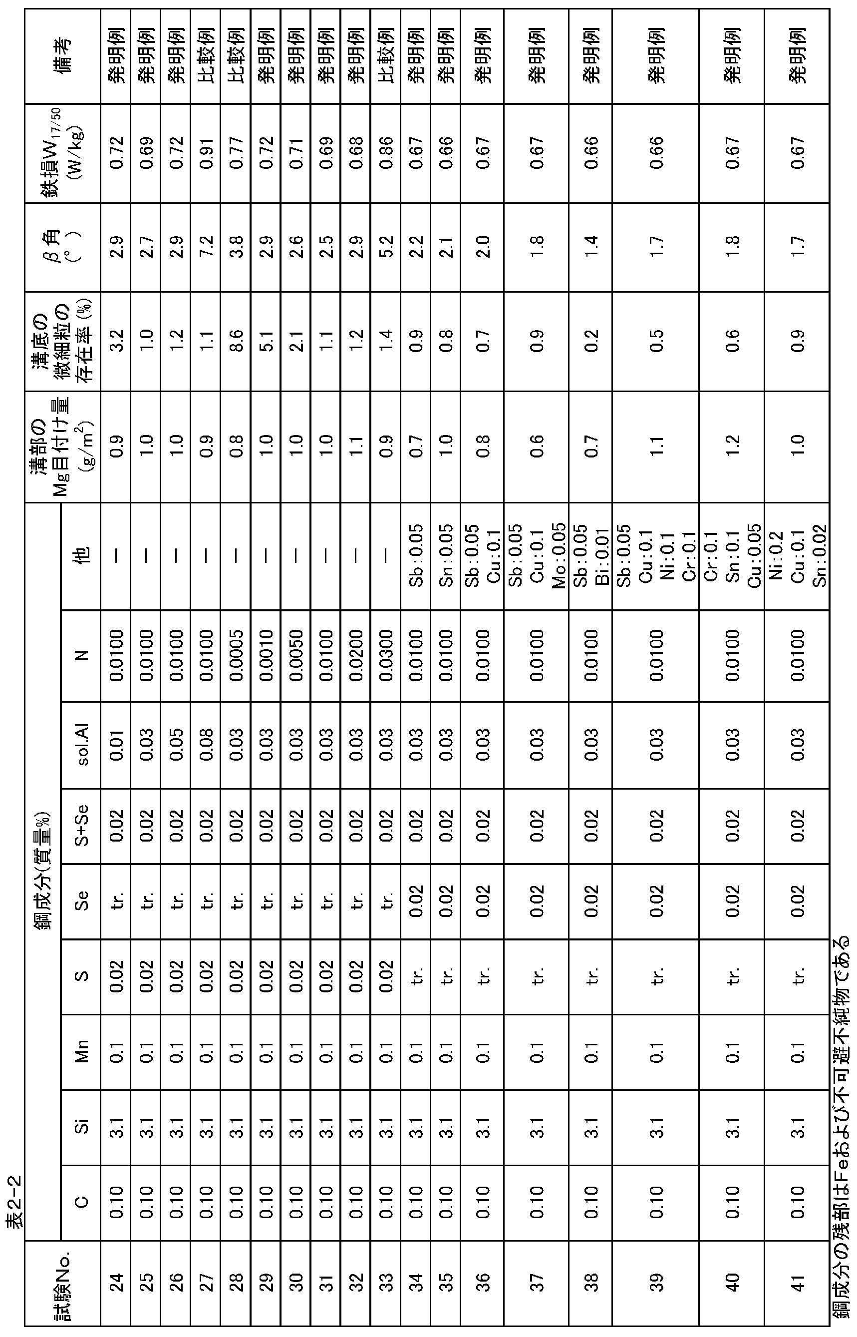

Claims (5)
- 表面に、圧延直角方向となす角度が45°以内の線状の溝を有する方向性電磁鋼板であって、該溝底部における、圧延方向への長さ:1mm以下の微細粒の存在頻度が10%以下(微細粒が存在しない場合も含む)であって、かつ該溝に、鋼板の片面あたりのMg目付量にして0.6g/m2以上のフォルステライト被膜を具え、さらに鋼板の圧延方向を向く二次再結晶粒の〈100〉軸と圧延面とのなす角(β角)が平均値で3°以下である方向性電磁鋼板。 It is a grain-oriented electrical steel sheet having a linear groove having an angle of 45 ° or less with the direction perpendicular to the rolling on the surface, and the length in the rolling direction at the bottom of the groove: the presence frequency of fine grains of 1 mm or less is 10 %, Including a case where fine grains are not present, and the groove has a forsterite coating of 0.6 g / m 2 or more in terms of the Mg basis weight per side of the steel sheet, and further the rolling direction of the steel sheet A grain-oriented electrical steel sheet in which the angle (β angle) formed between the <100> axis of the secondary recrystallized grains facing and the rolling surface is 3 ° or less on average.
- 質量%で、C:0.01~0.20%、Si:2.0~5.0%、Mn:0.03~0.20%、sol.Al:0.010~0.05%およびN:0.0010~0.020%を含有し、かつSおよびSeのうちから選んだ1種または2種の合計:0.005~0.040%を含み、残部はFeおよび不可避不純物からなる鋼スラブを、冷間圧延を含む圧延工程によって最終板厚とし、ついで化学的な手段により、圧延直角方向となす角度が45°以内の線状に伸びる溝を形成したのち、脱炭焼鈍し、その後MgOを主体とする焼鈍分離剤を塗布してから最終仕上げ焼鈍を施す一連の工程からなる方向性電磁鋼板の製造方法において、上記MgOとして、その粘度が水との混合後30分経過時に20~100cPの範囲を満たすものを用い、かつ上記冷間圧延における最終冷延工程において、圧延スタンドの入側・出側温度のうち、高い方の温度が170℃以下となる圧延を少なくとも1回、また200℃以上となる圧延を少なくとも2回施す方向性電磁鋼板の製造方法。 In mass%, C: 0.01-0.20%, Si: 2.0-5.0%, Mn: 0.03-0.20%, sol.Al: 0.010-0.05% and N: 0.0010-0.020%, and among S and Se A total of one or two selected from: 0.005 to 0.040%, and the balance of steel slab consisting of Fe and inevitable impurities is made the final thickness by a rolling process including cold rolling, and then by chemical means, After forming a linearly extending groove with an angle of 45 ° or less with the direction perpendicular to rolling, decarburization annealing is performed, and then a final finishing annealing is performed after applying an annealing separator mainly composed of MgO. In the method for producing grain-oriented electrical steel sheets, the MgO having a viscosity satisfying the range of 20 to 100 cP after 30 minutes of mixing with water is used, and in the final cold rolling step in the cold rolling, a rolling stand Of the inlet and outlet temperatures, the higher temperature is 170 ° C or less At least once, also a manufacturing method of a grain-oriented electrical steel sheet is subjected at least twice rolling the 200 ° C. or more rolling made.
- 前記鋼スラブが、さらに、質量%で、Cu:0.01~0.2%,Ni:0.01~0.5%,Cr:0.01~0.5%,Sb:0.01~0.1%,Sn:0.01~0.5%,Mo:0.01~0.5%およびBi:0.001~0.1%のうちから選んだ少なくとも1種を含有する請求項2に記載の方向性電磁鋼板の製造方法。 The steel slab is further, in mass%, Cu: 0.01 to 0.2%, Ni: 0.01 to 0.5%, Cr: 0.01 to 0.5%, Sb: 0.01 to 0.1%, Sn: 0.01 to 0.5%, Mo: 0.01 to The method for producing a grain-oriented electrical steel sheet according to claim 2, comprising at least one selected from 0.5% and Bi: 0.001 to 0.1%.
- 前記化学的な手段が、電解エッチングまたは酸洗処理である請求項2または3に記載の方向性電磁鋼板の製造方法。 4. The method for producing a grain-oriented electrical steel sheet according to claim 2, wherein the chemical means is electrolytic etching or pickling treatment.
- 前記冷間圧延を含む圧延工程が、前記鋼スラブを、加熱後、熱間圧延し、ついで熱延板焼鈍を施したのち、1回の冷間圧延、または中間焼鈍を含む2回以上の冷間圧延によって最終板厚とする工程である請求項2~4のいずれかに記載の方向性電磁鋼板の製造方法。 In the rolling process including the cold rolling, the steel slab is heated and then hot-rolled, and then subjected to hot-rolled sheet annealing, and then cold-cooled twice or more including intermediate annealing. The method for producing a grain-oriented electrical steel sheet according to any one of claims 2 to 4, which is a step of obtaining a final sheet thickness by hot rolling.
Priority Applications (8)
| Application Number | Priority Date | Filing Date | Title |
|---|---|---|---|
| IN1807MUN2014 IN2014MN01807A (en) | 2012-04-26 | 2012-04-26 | |
| CN201280072609.9A CN104284994B (en) | 2012-04-26 | 2012-04-26 | Orientation electromagnetic steel plate and its manufacture method |
| RU2014147446/02A RU2601022C2 (en) | 2012-04-26 | 2012-04-26 | Textured electrical steel sheet and method of its producing |
| KR1020147029128A KR101636191B1 (en) | 2012-04-26 | 2012-04-26 | Grain-oriented electrical steel sheet and method for manufacturing same |
| EP12875534.5A EP2843069B1 (en) | 2012-04-26 | 2012-04-26 | Grain-oriented electrical steel sheet and method for manufacturing same |
| PCT/JP2012/002875 WO2013160955A1 (en) | 2012-04-26 | 2012-04-26 | Grain-oriented electrical steel sheet and method for manufacturing same |
| US14/395,900 US9704626B2 (en) | 2012-04-26 | 2012-04-26 | Grain-oriented electrical steel sheet and method of manufacturing same |
| US15/606,074 US10629346B2 (en) | 2012-04-26 | 2017-05-26 | Method of manufacturing grain-oriented electrical steel sheet |
Applications Claiming Priority (1)
| Application Number | Priority Date | Filing Date | Title |
|---|---|---|---|
| PCT/JP2012/002875 WO2013160955A1 (en) | 2012-04-26 | 2012-04-26 | Grain-oriented electrical steel sheet and method for manufacturing same |
Related Child Applications (2)
| Application Number | Title | Priority Date | Filing Date |
|---|---|---|---|
| US14/395,900 A-371-Of-International US9704626B2 (en) | 2012-04-26 | 2012-04-26 | Grain-oriented electrical steel sheet and method of manufacturing same |
| US15/606,074 Division US10629346B2 (en) | 2012-04-26 | 2017-05-26 | Method of manufacturing grain-oriented electrical steel sheet |
Publications (1)
| Publication Number | Publication Date |
|---|---|
| WO2013160955A1 true WO2013160955A1 (en) | 2013-10-31 |
Family
ID=49482332
Family Applications (1)
| Application Number | Title | Priority Date | Filing Date |
|---|---|---|---|
| PCT/JP2012/002875 WO2013160955A1 (en) | 2012-04-26 | 2012-04-26 | Grain-oriented electrical steel sheet and method for manufacturing same |
Country Status (7)
| Country | Link |
|---|---|
| US (1) | US9704626B2 (en) |
| EP (1) | EP2843069B1 (en) |
| KR (1) | KR101636191B1 (en) |
| CN (1) | CN104284994B (en) |
| IN (1) | IN2014MN01807A (en) |
| RU (1) | RU2601022C2 (en) |
| WO (1) | WO2013160955A1 (en) |
Cited By (5)
| Publication number | Priority date | Publication date | Assignee | Title |
|---|---|---|---|---|
| KR101538778B1 (en) * | 2013-12-24 | 2015-07-22 | 주식회사 포스코 | Grain-oriented electrical steel sheet and method for manufacturing the same |
| EP3205738A4 (en) * | 2014-10-06 | 2017-08-30 | JFE Steel Corporation | Low-core-loss grain-oriented electromagnetic steel sheet and method for manufacturing same |
| WO2019065645A1 (en) * | 2017-09-28 | 2019-04-04 | Jfeスチール株式会社 | Grain-oriented electrical steel sheet |
| JP2021025128A (en) * | 2019-07-31 | 2021-02-22 | Jfeスチール株式会社 | Grain oriented electrical steel sheet |
| JP2022509866A (en) * | 2018-11-30 | 2022-01-24 | ポスコ | Directional electrical steel sheet and its manufacturing method |
Families Citing this family (16)
| Publication number | Priority date | Publication date | Assignee | Title |
|---|---|---|---|---|
| KR101693516B1 (en) | 2014-12-24 | 2017-01-06 | 주식회사 포스코 | Grain-orientied electrical steel sheet and method for manufacturing the smae |
| WO2016105053A1 (en) * | 2014-12-24 | 2016-06-30 | 주식회사 포스코 | Grain-oriented electrical steel plate and production method therefor |
| JP6233334B2 (en) | 2015-03-04 | 2017-11-22 | Jfeスチール株式会社 | Continuous electrolytic etching method for directional electrical steel strip and continuous electrolytic etching apparatus for directional electrical steel strip |
| US10434606B2 (en) | 2015-04-20 | 2019-10-08 | Nippon Steel Corporation | Grain-oriented electrical steel sheet |
| KR102010166B1 (en) * | 2015-04-20 | 2019-08-12 | 닛폰세이테츠 가부시키가이샤 | Directional electromagnetic steel plate |
| CN106282512B (en) * | 2015-05-11 | 2018-03-30 | 宝山钢铁股份有限公司 | Low noise level transformer orientation silicon steel piece making method |
| CN105244135B (en) * | 2015-09-24 | 2018-03-30 | 国网智能电网研究院 | A kind of electrical sheet sheet material and preparation method thereof |
| KR101701193B1 (en) | 2015-10-20 | 2017-02-01 | 주식회사 포스코 | Composition for forming insulation film of oriented electrical steel sheet, method for forming insulating film using the same, and insulation film formed oriented electrical steel sheet |
| JP6572855B2 (en) * | 2016-09-21 | 2019-09-11 | Jfeスチール株式会社 | Oriented electrical steel sheet and manufacturing method thereof |
| JP6372581B1 (en) * | 2017-02-17 | 2018-08-15 | Jfeスチール株式会社 | Oriented electrical steel sheet |
| US11236427B2 (en) | 2017-12-06 | 2022-02-01 | Polyvision Corporation | Systems and methods for in-line thermal flattening and enameling of steel sheets |
| KR102448815B1 (en) * | 2018-01-31 | 2022-09-29 | 닛폰세이테츠 가부시키가이샤 | grain-oriented electrical steel sheet |
| KR102360385B1 (en) * | 2018-01-31 | 2022-02-08 | 제이에프이 스틸 가부시키가이샤 | Grain-oriented electrical steel sheet and method for manufacturing the wound iron core and the wound iron core of a transformer made using the same |
| RU2764010C1 (en) * | 2018-07-31 | 2022-01-12 | Ниппон Стил Корпорейшн | Sheet of electrical steel with oriented grain structure |
| KR102176348B1 (en) * | 2018-11-30 | 2020-11-09 | 주식회사 포스코 | Grain oriented electrical steel sheet and manufacturing method of the same |
| KR102164329B1 (en) * | 2018-12-19 | 2020-10-12 | 주식회사 포스코 | Grain oriented electrical steel sheet and method for manufacturing therof |
Citations (7)
| Publication number | Priority date | Publication date | Assignee | Title |
|---|---|---|---|---|
| JPS55110732A (en) * | 1979-02-16 | 1980-08-26 | Kawasaki Steel Corp | Formation of uniform insulating film on grain-oriented silicone steel plate |
| JPH09157745A (en) * | 1995-12-01 | 1997-06-17 | Kawasaki Steel Corp | Manufacture of grain oriented silicon steel sheet excellent in magnetic property |
| JPH10226819A (en) * | 1996-12-13 | 1998-08-25 | Kawasaki Steel Corp | Production of grain oriented silicon steel sheet excellent in core loss characteristic |
| JP2007246973A (en) * | 2006-03-15 | 2007-09-27 | Jfe Steel Kk | Annealing-separating agent slurry for grain-oriented magnetic steel sheet and preparing method therefor, and method for producing grain-oriented magnetic steel sheet |
| JP2012036446A (en) * | 2010-08-06 | 2012-02-23 | Jfe Steel Corp | Grain-oriented electrical steel sheet and method for producing the same |
| JP2012077380A (en) * | 2010-09-10 | 2012-04-19 | Jfe Steel Corp | Grain-oriented electromagnetic steel sheet, and method for manufacturing the same |
| JP2012126973A (en) * | 2010-12-16 | 2012-07-05 | Jfe Steel Corp | Grain-oriented electromagnetic steel sheet, and method for manufacturing the same |
Family Cites Families (16)
| Publication number | Priority date | Publication date | Assignee | Title |
|---|---|---|---|---|
| CA1061161A (en) * | 1974-09-12 | 1979-08-28 | Joseph J. Piascinski | Method for making an etch-resistant stencil |
| JPS5518566A (en) | 1978-07-26 | 1980-02-08 | Nippon Steel Corp | Improving method for iron loss characteristic of directional electrical steel sheet |
| GR75219B (en) | 1980-04-21 | 1984-07-13 | Merck & Co Inc | |
| JPS61117218A (en) | 1984-11-10 | 1986-06-04 | Nippon Steel Corp | Manufacture of grain oriented magnetic steel sheet of low iron loss |
| JPS61117284A (en) | 1984-11-10 | 1986-06-04 | Nippon Steel Corp | Production of low-iron loss grain-oriented electromagnetic steel sheet |
| JPS6253579A (en) | 1985-09-03 | 1987-03-09 | Seiko Epson Corp | Portable receiver |
| JPS6254873A (en) | 1985-09-03 | 1987-03-10 | Sanyo Electric Co Ltd | Fixed-head type digital magnetic reproducing device |
| JPH0369968A (en) | 1989-08-09 | 1991-03-26 | Canon Inc | Copying device |
| JP3082460B2 (en) | 1992-08-31 | 2000-08-28 | タカタ株式会社 | Airbag device |
| JP3726289B2 (en) | 1994-03-31 | 2005-12-14 | Jfeスチール株式会社 | Oriented electrical steel sheet with low iron loss |
| JP3470475B2 (en) * | 1995-11-27 | 2003-11-25 | Jfeスチール株式会社 | Grain-oriented electrical steel sheet with extremely low iron loss and its manufacturing method |
| EP0892072B1 (en) * | 1997-07-17 | 2003-01-22 | Kawasaki Steel Corporation | Grain-oriented electrical steel sheet excellent in magnetic characteristics and production process for same |
| JP2002220642A (en) | 2001-01-29 | 2002-08-09 | Kawasaki Steel Corp | Grain-oriented electromagnetic steel sheet with low iron loss and manufacturing method therefor |
| JP4331900B2 (en) * | 2001-03-30 | 2009-09-16 | 新日本製鐵株式会社 | Oriented electrical steel sheet and method and apparatus for manufacturing the same |
| JP5181651B2 (en) * | 2007-12-14 | 2013-04-10 | Jfeスチール株式会社 | Method for adjusting annealing separator slurry for grain-oriented electrical steel sheet and method for producing grain-oriented electrical steel sheet |
| RU2371521C1 (en) * | 2008-03-06 | 2009-10-27 | Федеральное государственное унитарное предприятие "Научно-производственное предприятие "Исток" (ФГУП НПП "Исток") | Manufacturing method of precision products from molybdenum and its alloys and solution for photochemical etching |
-
2012
- 2012-04-26 KR KR1020147029128A patent/KR101636191B1/en active IP Right Grant
- 2012-04-26 US US14/395,900 patent/US9704626B2/en active Active
- 2012-04-26 WO PCT/JP2012/002875 patent/WO2013160955A1/en active Application Filing
- 2012-04-26 CN CN201280072609.9A patent/CN104284994B/en active Active
- 2012-04-26 RU RU2014147446/02A patent/RU2601022C2/en active
- 2012-04-26 IN IN1807MUN2014 patent/IN2014MN01807A/en unknown
- 2012-04-26 EP EP12875534.5A patent/EP2843069B1/en active Active
Patent Citations (7)
| Publication number | Priority date | Publication date | Assignee | Title |
|---|---|---|---|---|
| JPS55110732A (en) * | 1979-02-16 | 1980-08-26 | Kawasaki Steel Corp | Formation of uniform insulating film on grain-oriented silicone steel plate |
| JPH09157745A (en) * | 1995-12-01 | 1997-06-17 | Kawasaki Steel Corp | Manufacture of grain oriented silicon steel sheet excellent in magnetic property |
| JPH10226819A (en) * | 1996-12-13 | 1998-08-25 | Kawasaki Steel Corp | Production of grain oriented silicon steel sheet excellent in core loss characteristic |
| JP2007246973A (en) * | 2006-03-15 | 2007-09-27 | Jfe Steel Kk | Annealing-separating agent slurry for grain-oriented magnetic steel sheet and preparing method therefor, and method for producing grain-oriented magnetic steel sheet |
| JP2012036446A (en) * | 2010-08-06 | 2012-02-23 | Jfe Steel Corp | Grain-oriented electrical steel sheet and method for producing the same |
| JP2012077380A (en) * | 2010-09-10 | 2012-04-19 | Jfe Steel Corp | Grain-oriented electromagnetic steel sheet, and method for manufacturing the same |
| JP2012126973A (en) * | 2010-12-16 | 2012-07-05 | Jfe Steel Corp | Grain-oriented electromagnetic steel sheet, and method for manufacturing the same |
Cited By (9)
| Publication number | Priority date | Publication date | Assignee | Title |
|---|---|---|---|---|
| KR101538778B1 (en) * | 2013-12-24 | 2015-07-22 | 주식회사 포스코 | Grain-oriented electrical steel sheet and method for manufacturing the same |
| EP3205738A4 (en) * | 2014-10-06 | 2017-08-30 | JFE Steel Corporation | Low-core-loss grain-oriented electromagnetic steel sheet and method for manufacturing same |
| WO2019065645A1 (en) * | 2017-09-28 | 2019-04-04 | Jfeスチール株式会社 | Grain-oriented electrical steel sheet |
| JPWO2019065645A1 (en) * | 2017-09-28 | 2019-11-14 | Jfeスチール株式会社 | Oriented electrical steel sheet |
| EP3690067A4 (en) * | 2017-09-28 | 2020-08-05 | JFE Steel Corporation | Grain-oriented electrical steel sheet |
| US11198916B2 (en) | 2017-09-28 | 2021-12-14 | Jfe Steel Corporation | Grain-oriented electrical steel sheet |
| JP2022509866A (en) * | 2018-11-30 | 2022-01-24 | ポスコ | Directional electrical steel sheet and its manufacturing method |
| JP2021025128A (en) * | 2019-07-31 | 2021-02-22 | Jfeスチール株式会社 | Grain oriented electrical steel sheet |
| JP7147810B2 (en) | 2019-07-31 | 2022-10-05 | Jfeスチール株式会社 | Oriented electrical steel sheet |
Also Published As
| Publication number | Publication date |
|---|---|
| KR20140135833A (en) | 2014-11-26 |
| RU2601022C2 (en) | 2016-10-27 |
| US9704626B2 (en) | 2017-07-11 |
| US20150111004A1 (en) | 2015-04-23 |
| CN104284994B (en) | 2017-03-01 |
| RU2014147446A (en) | 2016-06-10 |
| CN104284994A (en) | 2015-01-14 |
| KR101636191B1 (en) | 2016-07-04 |
| IN2014MN01807A (en) | 2015-07-03 |
| EP2843069A1 (en) | 2015-03-04 |
| EP2843069B1 (en) | 2019-06-05 |
| EP2843069A4 (en) | 2015-09-09 |
Similar Documents
| Publication | Publication Date | Title |
|---|---|---|
| WO2013160955A1 (en) | Grain-oriented electrical steel sheet and method for manufacturing same | |
| JP5754097B2 (en) | Oriented electrical steel sheet and manufacturing method thereof | |
| JP5793859B2 (en) | Oriented electrical steel sheet and manufacturing method thereof | |
| KR101600724B1 (en) | Method of producing grain-oriented electrical steel sheet having excellent iron loss properties | |
| RU2706990C1 (en) | Textured electrical steel sheet and method of its manufacturing | |
| WO2016056501A1 (en) | Low-core-loss grain-oriented electromagnetic steel sheet and method for manufacturing same | |
| JP5668893B2 (en) | Method for producing grain-oriented electrical steel sheet | |
| WO2013058239A1 (en) | Oriented electromagnetic steel sheet and method for manufacturing same | |
| US10629346B2 (en) | Method of manufacturing grain-oriented electrical steel sheet | |
| JP2017222898A (en) | Production method of grain oriented magnetic steel sheet | |
| CN108699621B (en) | Method for producing grain-oriented electromagnetic steel sheet | |
| JP6443355B2 (en) | Method for producing grain-oriented electrical steel sheet | |
| JP2012126980A (en) | Electromagnetic steel sheet and method for manufacturing the same | |
| JP6191568B2 (en) | Method for producing grain-oriented electrical steel sheet | |
| JP2017106111A (en) | Manufacturing method of oriented electromagnetic steel sheet | |
| WO2019131974A1 (en) | Oriented electromagnetic steel sheet | |
| JP3390345B2 (en) | Grain-oriented electrical steel sheet having excellent magnetic properties and method for producing the same | |
| JP4258185B2 (en) | Oriented electrical steel sheet and manufacturing method thereof | |
| JP6690244B2 (en) | Bidirectional electrical steel sheet and method for manufacturing bidirectional electrical steel sheet | |
| JP7352082B2 (en) | Non-oriented electrical steel sheet | |
| EP4174194A1 (en) | Production method for grain-oriented electrical steel sheet | |
| JP2011063829A (en) | Method for manufacturing grain-oriented magnetic steel sheet | |
| JP2003193141A (en) | Method of producing grain oriented silicon steel sheet having excellent coating property | |
| JP2004115858A (en) | Method for manufacturing grain-oriented electromagnetic steel sheet superior in magnetic property | |
| JP7338511B2 (en) | Manufacturing method of grain-oriented electrical steel sheet |
Legal Events
| Date | Code | Title | Description |
|---|---|---|---|
| 121 | Ep: the epo has been informed by wipo that ep was designated in this application |
Ref document number: 12875534 Country of ref document: EP Kind code of ref document: A1 |
|
| ENP | Entry into the national phase |
Ref document number: 20147029128 Country of ref document: KR Kind code of ref document: A |
|
| WWE | Wipo information: entry into national phase |
Ref document number: 14395900 Country of ref document: US Ref document number: 2012875534 Country of ref document: EP |
|
| NENP | Non-entry into the national phase |
Ref country code: DE |
|
| ENP | Entry into the national phase |
Ref document number: 2014147446 Country of ref document: RU Kind code of ref document: A |
|
| NENP | Non-entry into the national phase |
Ref country code: JP |