WO2013157239A1 - Ralentisseur - Google Patents
Ralentisseur Download PDFInfo
- Publication number
- WO2013157239A1 WO2013157239A1 PCT/JP2013/002541 JP2013002541W WO2013157239A1 WO 2013157239 A1 WO2013157239 A1 WO 2013157239A1 JP 2013002541 W JP2013002541 W JP 2013002541W WO 2013157239 A1 WO2013157239 A1 WO 2013157239A1
- Authority
- WO
- WIPO (PCT)
- Prior art keywords
- induction motor
- transmission
- speed sensor
- rotational speed
- control
- Prior art date
Links
Images

Classifications
-
- B—PERFORMING OPERATIONS; TRANSPORTING
- B60—VEHICLES IN GENERAL
- B60L—PROPULSION OF ELECTRICALLY-PROPELLED VEHICLES; SUPPLYING ELECTRIC POWER FOR AUXILIARY EQUIPMENT OF ELECTRICALLY-PROPELLED VEHICLES; ELECTRODYNAMIC BRAKE SYSTEMS FOR VEHICLES IN GENERAL; MAGNETIC SUSPENSION OR LEVITATION FOR VEHICLES; MONITORING OPERATING VARIABLES OF ELECTRICALLY-PROPELLED VEHICLES; ELECTRIC SAFETY DEVICES FOR ELECTRICALLY-PROPELLED VEHICLES
- B60L7/00—Electrodynamic brake systems for vehicles in general
- B60L7/10—Dynamic electric regenerative braking
- B60L7/14—Dynamic electric regenerative braking for vehicles propelled by ac motors
-
- B—PERFORMING OPERATIONS; TRANSPORTING
- B60—VEHICLES IN GENERAL
- B60K—ARRANGEMENT OR MOUNTING OF PROPULSION UNITS OR OF TRANSMISSIONS IN VEHICLES; ARRANGEMENT OR MOUNTING OF PLURAL DIVERSE PRIME-MOVERS IN VEHICLES; AUXILIARY DRIVES FOR VEHICLES; INSTRUMENTATION OR DASHBOARDS FOR VEHICLES; ARRANGEMENTS IN CONNECTION WITH COOLING, AIR INTAKE, GAS EXHAUST OR FUEL SUPPLY OF PROPULSION UNITS IN VEHICLES
- B60K6/00—Arrangement or mounting of plural diverse prime-movers for mutual or common propulsion, e.g. hybrid propulsion systems comprising electric motors and internal combustion engines ; Control systems therefor, i.e. systems controlling two or more prime movers, or controlling one of these prime movers and any of the transmission, drive or drive units Informative references: mechanical gearings with secondary electric drive F16H3/72; arrangements for handling mechanical energy structurally associated with the dynamo-electric machine H02K7/00; machines comprising structurally interrelated motor and generator parts H02K51/00; dynamo-electric machines not otherwise provided for in H02K see H02K99/00
- B60K6/20—Arrangement or mounting of plural diverse prime-movers for mutual or common propulsion, e.g. hybrid propulsion systems comprising electric motors and internal combustion engines ; Control systems therefor, i.e. systems controlling two or more prime movers, or controlling one of these prime movers and any of the transmission, drive or drive units Informative references: mechanical gearings with secondary electric drive F16H3/72; arrangements for handling mechanical energy structurally associated with the dynamo-electric machine H02K7/00; machines comprising structurally interrelated motor and generator parts H02K51/00; dynamo-electric machines not otherwise provided for in H02K see H02K99/00 the prime-movers consisting of electric motors and internal combustion engines, e.g. HEVs
- B60K6/42—Arrangement or mounting of plural diverse prime-movers for mutual or common propulsion, e.g. hybrid propulsion systems comprising electric motors and internal combustion engines ; Control systems therefor, i.e. systems controlling two or more prime movers, or controlling one of these prime movers and any of the transmission, drive or drive units Informative references: mechanical gearings with secondary electric drive F16H3/72; arrangements for handling mechanical energy structurally associated with the dynamo-electric machine H02K7/00; machines comprising structurally interrelated motor and generator parts H02K51/00; dynamo-electric machines not otherwise provided for in H02K see H02K99/00 the prime-movers consisting of electric motors and internal combustion engines, e.g. HEVs characterised by the architecture of the hybrid electric vehicle
- B60K6/48—Parallel type
-
- B—PERFORMING OPERATIONS; TRANSPORTING
- B60—VEHICLES IN GENERAL
- B60L—PROPULSION OF ELECTRICALLY-PROPELLED VEHICLES; SUPPLYING ELECTRIC POWER FOR AUXILIARY EQUIPMENT OF ELECTRICALLY-PROPELLED VEHICLES; ELECTRODYNAMIC BRAKE SYSTEMS FOR VEHICLES IN GENERAL; MAGNETIC SUSPENSION OR LEVITATION FOR VEHICLES; MONITORING OPERATING VARIABLES OF ELECTRICALLY-PROPELLED VEHICLES; ELECTRIC SAFETY DEVICES FOR ELECTRICALLY-PROPELLED VEHICLES
- B60L15/00—Methods, circuits, or devices for controlling the traction-motor speed of electrically-propelled vehicles
- B60L15/20—Methods, circuits, or devices for controlling the traction-motor speed of electrically-propelled vehicles for control of the vehicle or its driving motor to achieve a desired performance, e.g. speed, torque, programmed variation of speed
- B60L15/2009—Methods, circuits, or devices for controlling the traction-motor speed of electrically-propelled vehicles for control of the vehicle or its driving motor to achieve a desired performance, e.g. speed, torque, programmed variation of speed for braking
-
- B—PERFORMING OPERATIONS; TRANSPORTING
- B60—VEHICLES IN GENERAL
- B60L—PROPULSION OF ELECTRICALLY-PROPELLED VEHICLES; SUPPLYING ELECTRIC POWER FOR AUXILIARY EQUIPMENT OF ELECTRICALLY-PROPELLED VEHICLES; ELECTRODYNAMIC BRAKE SYSTEMS FOR VEHICLES IN GENERAL; MAGNETIC SUSPENSION OR LEVITATION FOR VEHICLES; MONITORING OPERATING VARIABLES OF ELECTRICALLY-PROPELLED VEHICLES; ELECTRIC SAFETY DEVICES FOR ELECTRICALLY-PROPELLED VEHICLES
- B60L50/00—Electric propulsion with power supplied within the vehicle
- B60L50/10—Electric propulsion with power supplied within the vehicle using propulsion power supplied by engine-driven generators, e.g. generators driven by combustion engines
- B60L50/16—Electric propulsion with power supplied within the vehicle using propulsion power supplied by engine-driven generators, e.g. generators driven by combustion engines with provision for separate direct mechanical propulsion
-
- B—PERFORMING OPERATIONS; TRANSPORTING
- B60—VEHICLES IN GENERAL
- B60K—ARRANGEMENT OR MOUNTING OF PROPULSION UNITS OR OF TRANSMISSIONS IN VEHICLES; ARRANGEMENT OR MOUNTING OF PLURAL DIVERSE PRIME-MOVERS IN VEHICLES; AUXILIARY DRIVES FOR VEHICLES; INSTRUMENTATION OR DASHBOARDS FOR VEHICLES; ARRANGEMENTS IN CONNECTION WITH COOLING, AIR INTAKE, GAS EXHAUST OR FUEL SUPPLY OF PROPULSION UNITS IN VEHICLES
- B60K6/00—Arrangement or mounting of plural diverse prime-movers for mutual or common propulsion, e.g. hybrid propulsion systems comprising electric motors and internal combustion engines ; Control systems therefor, i.e. systems controlling two or more prime movers, or controlling one of these prime movers and any of the transmission, drive or drive units Informative references: mechanical gearings with secondary electric drive F16H3/72; arrangements for handling mechanical energy structurally associated with the dynamo-electric machine H02K7/00; machines comprising structurally interrelated motor and generator parts H02K51/00; dynamo-electric machines not otherwise provided for in H02K see H02K99/00
- B60K6/20—Arrangement or mounting of plural diverse prime-movers for mutual or common propulsion, e.g. hybrid propulsion systems comprising electric motors and internal combustion engines ; Control systems therefor, i.e. systems controlling two or more prime movers, or controlling one of these prime movers and any of the transmission, drive or drive units Informative references: mechanical gearings with secondary electric drive F16H3/72; arrangements for handling mechanical energy structurally associated with the dynamo-electric machine H02K7/00; machines comprising structurally interrelated motor and generator parts H02K51/00; dynamo-electric machines not otherwise provided for in H02K see H02K99/00 the prime-movers consisting of electric motors and internal combustion engines, e.g. HEVs
- B60K6/42—Arrangement or mounting of plural diverse prime-movers for mutual or common propulsion, e.g. hybrid propulsion systems comprising electric motors and internal combustion engines ; Control systems therefor, i.e. systems controlling two or more prime movers, or controlling one of these prime movers and any of the transmission, drive or drive units Informative references: mechanical gearings with secondary electric drive F16H3/72; arrangements for handling mechanical energy structurally associated with the dynamo-electric machine H02K7/00; machines comprising structurally interrelated motor and generator parts H02K51/00; dynamo-electric machines not otherwise provided for in H02K see H02K99/00 the prime-movers consisting of electric motors and internal combustion engines, e.g. HEVs characterised by the architecture of the hybrid electric vehicle
- B60K6/48—Parallel type
- B60K2006/4808—Electric machine connected or connectable to gearbox output shaft
-
- B—PERFORMING OPERATIONS; TRANSPORTING
- B60—VEHICLES IN GENERAL
- B60L—PROPULSION OF ELECTRICALLY-PROPELLED VEHICLES; SUPPLYING ELECTRIC POWER FOR AUXILIARY EQUIPMENT OF ELECTRICALLY-PROPELLED VEHICLES; ELECTRODYNAMIC BRAKE SYSTEMS FOR VEHICLES IN GENERAL; MAGNETIC SUSPENSION OR LEVITATION FOR VEHICLES; MONITORING OPERATING VARIABLES OF ELECTRICALLY-PROPELLED VEHICLES; ELECTRIC SAFETY DEVICES FOR ELECTRICALLY-PROPELLED VEHICLES
- B60L2210/00—Converter types
- B60L2210/40—DC to AC converters
-
- B—PERFORMING OPERATIONS; TRANSPORTING
- B60—VEHICLES IN GENERAL
- B60L—PROPULSION OF ELECTRICALLY-PROPELLED VEHICLES; SUPPLYING ELECTRIC POWER FOR AUXILIARY EQUIPMENT OF ELECTRICALLY-PROPELLED VEHICLES; ELECTRODYNAMIC BRAKE SYSTEMS FOR VEHICLES IN GENERAL; MAGNETIC SUSPENSION OR LEVITATION FOR VEHICLES; MONITORING OPERATING VARIABLES OF ELECTRICALLY-PROPELLED VEHICLES; ELECTRIC SAFETY DEVICES FOR ELECTRICALLY-PROPELLED VEHICLES
- B60L2220/00—Electrical machine types; Structures or applications thereof
- B60L2220/10—Electrical machine types
- B60L2220/12—Induction machines
-
- B—PERFORMING OPERATIONS; TRANSPORTING
- B60—VEHICLES IN GENERAL
- B60L—PROPULSION OF ELECTRICALLY-PROPELLED VEHICLES; SUPPLYING ELECTRIC POWER FOR AUXILIARY EQUIPMENT OF ELECTRICALLY-PROPELLED VEHICLES; ELECTRODYNAMIC BRAKE SYSTEMS FOR VEHICLES IN GENERAL; MAGNETIC SUSPENSION OR LEVITATION FOR VEHICLES; MONITORING OPERATING VARIABLES OF ELECTRICALLY-PROPELLED VEHICLES; ELECTRIC SAFETY DEVICES FOR ELECTRICALLY-PROPELLED VEHICLES
- B60L2240/00—Control parameters of input or output; Target parameters
- B60L2240/10—Vehicle control parameters
- B60L2240/12—Speed
-
- B—PERFORMING OPERATIONS; TRANSPORTING
- B60—VEHICLES IN GENERAL
- B60L—PROPULSION OF ELECTRICALLY-PROPELLED VEHICLES; SUPPLYING ELECTRIC POWER FOR AUXILIARY EQUIPMENT OF ELECTRICALLY-PROPELLED VEHICLES; ELECTRODYNAMIC BRAKE SYSTEMS FOR VEHICLES IN GENERAL; MAGNETIC SUSPENSION OR LEVITATION FOR VEHICLES; MONITORING OPERATING VARIABLES OF ELECTRICALLY-PROPELLED VEHICLES; ELECTRIC SAFETY DEVICES FOR ELECTRICALLY-PROPELLED VEHICLES
- B60L2240/00—Control parameters of input or output; Target parameters
- B60L2240/40—Drive Train control parameters
- B60L2240/42—Drive Train control parameters related to electric machines
- B60L2240/421—Speed
-
- B—PERFORMING OPERATIONS; TRANSPORTING
- B60—VEHICLES IN GENERAL
- B60L—PROPULSION OF ELECTRICALLY-PROPELLED VEHICLES; SUPPLYING ELECTRIC POWER FOR AUXILIARY EQUIPMENT OF ELECTRICALLY-PROPELLED VEHICLES; ELECTRODYNAMIC BRAKE SYSTEMS FOR VEHICLES IN GENERAL; MAGNETIC SUSPENSION OR LEVITATION FOR VEHICLES; MONITORING OPERATING VARIABLES OF ELECTRICALLY-PROPELLED VEHICLES; ELECTRIC SAFETY DEVICES FOR ELECTRICALLY-PROPELLED VEHICLES
- B60L2240/00—Control parameters of input or output; Target parameters
- B60L2240/40—Drive Train control parameters
- B60L2240/42—Drive Train control parameters related to electric machines
- B60L2240/423—Torque
-
- B—PERFORMING OPERATIONS; TRANSPORTING
- B60—VEHICLES IN GENERAL
- B60L—PROPULSION OF ELECTRICALLY-PROPELLED VEHICLES; SUPPLYING ELECTRIC POWER FOR AUXILIARY EQUIPMENT OF ELECTRICALLY-PROPELLED VEHICLES; ELECTRODYNAMIC BRAKE SYSTEMS FOR VEHICLES IN GENERAL; MAGNETIC SUSPENSION OR LEVITATION FOR VEHICLES; MONITORING OPERATING VARIABLES OF ELECTRICALLY-PROPELLED VEHICLES; ELECTRIC SAFETY DEVICES FOR ELECTRICALLY-PROPELLED VEHICLES
- B60L2240/00—Control parameters of input or output; Target parameters
- B60L2240/40—Drive Train control parameters
- B60L2240/42—Drive Train control parameters related to electric machines
- B60L2240/425—Temperature
-
- B—PERFORMING OPERATIONS; TRANSPORTING
- B60—VEHICLES IN GENERAL
- B60L—PROPULSION OF ELECTRICALLY-PROPELLED VEHICLES; SUPPLYING ELECTRIC POWER FOR AUXILIARY EQUIPMENT OF ELECTRICALLY-PROPELLED VEHICLES; ELECTRODYNAMIC BRAKE SYSTEMS FOR VEHICLES IN GENERAL; MAGNETIC SUSPENSION OR LEVITATION FOR VEHICLES; MONITORING OPERATING VARIABLES OF ELECTRICALLY-PROPELLED VEHICLES; ELECTRIC SAFETY DEVICES FOR ELECTRICALLY-PROPELLED VEHICLES
- B60L2240/00—Control parameters of input or output; Target parameters
- B60L2240/40—Drive Train control parameters
- B60L2240/44—Drive Train control parameters related to combustion engines
- B60L2240/441—Speed
-
- B—PERFORMING OPERATIONS; TRANSPORTING
- B60—VEHICLES IN GENERAL
- B60L—PROPULSION OF ELECTRICALLY-PROPELLED VEHICLES; SUPPLYING ELECTRIC POWER FOR AUXILIARY EQUIPMENT OF ELECTRICALLY-PROPELLED VEHICLES; ELECTRODYNAMIC BRAKE SYSTEMS FOR VEHICLES IN GENERAL; MAGNETIC SUSPENSION OR LEVITATION FOR VEHICLES; MONITORING OPERATING VARIABLES OF ELECTRICALLY-PROPELLED VEHICLES; ELECTRIC SAFETY DEVICES FOR ELECTRICALLY-PROPELLED VEHICLES
- B60L2240/00—Control parameters of input or output; Target parameters
- B60L2240/40—Drive Train control parameters
- B60L2240/44—Drive Train control parameters related to combustion engines
- B60L2240/443—Torque
-
- B—PERFORMING OPERATIONS; TRANSPORTING
- B60—VEHICLES IN GENERAL
- B60L—PROPULSION OF ELECTRICALLY-PROPELLED VEHICLES; SUPPLYING ELECTRIC POWER FOR AUXILIARY EQUIPMENT OF ELECTRICALLY-PROPELLED VEHICLES; ELECTRODYNAMIC BRAKE SYSTEMS FOR VEHICLES IN GENERAL; MAGNETIC SUSPENSION OR LEVITATION FOR VEHICLES; MONITORING OPERATING VARIABLES OF ELECTRICALLY-PROPELLED VEHICLES; ELECTRIC SAFETY DEVICES FOR ELECTRICALLY-PROPELLED VEHICLES
- B60L2240/00—Control parameters of input or output; Target parameters
- B60L2240/40—Drive Train control parameters
- B60L2240/48—Drive Train control parameters related to transmissions
- B60L2240/486—Operating parameters
-
- B—PERFORMING OPERATIONS; TRANSPORTING
- B60—VEHICLES IN GENERAL
- B60W—CONJOINT CONTROL OF VEHICLE SUB-UNITS OF DIFFERENT TYPE OR DIFFERENT FUNCTION; CONTROL SYSTEMS SPECIALLY ADAPTED FOR HYBRID VEHICLES; ROAD VEHICLE DRIVE CONTROL SYSTEMS FOR PURPOSES NOT RELATED TO THE CONTROL OF A PARTICULAR SUB-UNIT
- B60W2510/00—Input parameters relating to a particular sub-units
- B60W2510/02—Clutches
- B60W2510/0208—Clutch engagement state, e.g. engaged or disengaged
-
- B—PERFORMING OPERATIONS; TRANSPORTING
- B60—VEHICLES IN GENERAL
- B60W—CONJOINT CONTROL OF VEHICLE SUB-UNITS OF DIFFERENT TYPE OR DIFFERENT FUNCTION; CONTROL SYSTEMS SPECIALLY ADAPTED FOR HYBRID VEHICLES; ROAD VEHICLE DRIVE CONTROL SYSTEMS FOR PURPOSES NOT RELATED TO THE CONTROL OF A PARTICULAR SUB-UNIT
- B60W2510/00—Input parameters relating to a particular sub-units
- B60W2510/06—Combustion engines, Gas turbines
- B60W2510/0638—Engine speed
- B60W2510/0652—Speed change rate
-
- B—PERFORMING OPERATIONS; TRANSPORTING
- B60—VEHICLES IN GENERAL
- B60W—CONJOINT CONTROL OF VEHICLE SUB-UNITS OF DIFFERENT TYPE OR DIFFERENT FUNCTION; CONTROL SYSTEMS SPECIALLY ADAPTED FOR HYBRID VEHICLES; ROAD VEHICLE DRIVE CONTROL SYSTEMS FOR PURPOSES NOT RELATED TO THE CONTROL OF A PARTICULAR SUB-UNIT
- B60W2510/00—Input parameters relating to a particular sub-units
- B60W2510/10—Change speed gearings
- B60W2510/1005—Transmission ratio engaged
- B60W2510/101—Transmission neutral state
-
- Y—GENERAL TAGGING OF NEW TECHNOLOGICAL DEVELOPMENTS; GENERAL TAGGING OF CROSS-SECTIONAL TECHNOLOGIES SPANNING OVER SEVERAL SECTIONS OF THE IPC; TECHNICAL SUBJECTS COVERED BY FORMER USPC CROSS-REFERENCE ART COLLECTIONS [XRACs] AND DIGESTS
- Y02—TECHNOLOGIES OR APPLICATIONS FOR MITIGATION OR ADAPTATION AGAINST CLIMATE CHANGE
- Y02T—CLIMATE CHANGE MITIGATION TECHNOLOGIES RELATED TO TRANSPORTATION
- Y02T10/00—Road transport of goods or passengers
- Y02T10/60—Other road transportation technologies with climate change mitigation effect
- Y02T10/62—Hybrid vehicles
-
- Y—GENERAL TAGGING OF NEW TECHNOLOGICAL DEVELOPMENTS; GENERAL TAGGING OF CROSS-SECTIONAL TECHNOLOGIES SPANNING OVER SEVERAL SECTIONS OF THE IPC; TECHNICAL SUBJECTS COVERED BY FORMER USPC CROSS-REFERENCE ART COLLECTIONS [XRACs] AND DIGESTS
- Y02—TECHNOLOGIES OR APPLICATIONS FOR MITIGATION OR ADAPTATION AGAINST CLIMATE CHANGE
- Y02T—CLIMATE CHANGE MITIGATION TECHNOLOGIES RELATED TO TRANSPORTATION
- Y02T10/00—Road transport of goods or passengers
- Y02T10/60—Other road transportation technologies with climate change mitigation effect
- Y02T10/64—Electric machine technologies in electromobility
-
- Y—GENERAL TAGGING OF NEW TECHNOLOGICAL DEVELOPMENTS; GENERAL TAGGING OF CROSS-SECTIONAL TECHNOLOGIES SPANNING OVER SEVERAL SECTIONS OF THE IPC; TECHNICAL SUBJECTS COVERED BY FORMER USPC CROSS-REFERENCE ART COLLECTIONS [XRACs] AND DIGESTS
- Y02—TECHNOLOGIES OR APPLICATIONS FOR MITIGATION OR ADAPTATION AGAINST CLIMATE CHANGE
- Y02T—CLIMATE CHANGE MITIGATION TECHNOLOGIES RELATED TO TRANSPORTATION
- Y02T10/00—Road transport of goods or passengers
- Y02T10/60—Other road transportation technologies with climate change mitigation effect
- Y02T10/7072—Electromobility specific charging systems or methods for batteries, ultracapacitors, supercapacitors or double-layer capacitors
-
- Y—GENERAL TAGGING OF NEW TECHNOLOGICAL DEVELOPMENTS; GENERAL TAGGING OF CROSS-SECTIONAL TECHNOLOGIES SPANNING OVER SEVERAL SECTIONS OF THE IPC; TECHNICAL SUBJECTS COVERED BY FORMER USPC CROSS-REFERENCE ART COLLECTIONS [XRACs] AND DIGESTS
- Y02—TECHNOLOGIES OR APPLICATIONS FOR MITIGATION OR ADAPTATION AGAINST CLIMATE CHANGE
- Y02T—CLIMATE CHANGE MITIGATION TECHNOLOGIES RELATED TO TRANSPORTATION
- Y02T10/00—Road transport of goods or passengers
- Y02T10/60—Other road transportation technologies with climate change mitigation effect
- Y02T10/72—Electric energy management in electromobility
Definitions
- the present invention relates to a retarder used in an automobile, and more particularly to a retarder including an induction motor capable of braking, generating power, and generating torque.
- an eddy current method or a fluid method is generally known.
- the conventional eddy current type retarder cannot generate power by itself and is generated during braking. It was not possible to regenerate the energy to be regenerated, so it was not possible to meet the recent demands for reducing fuel consumption. Furthermore, since the retarder itself could not generate the driving torque that urges the output of the engine, it could not be used as auxiliary power for the vehicle.
- Patent Documents 1 and 2 a retarder having an induction motor capable of braking, generating power and generating torque has been proposed as an eddy current type retarder.
- the principle of sensorless control that has been proposed in the past is to detect the difference between the theoretical value and the actual value of the induced electromotive force generated in the stator when the rotor is controlled to rotate at a predetermined rotational speed.
- the rotational speed command value By controlling the rotational speed command value based on the amount of deviation, the rotational speed of the rotor is estimated and the rotational speed of the rotor is controlled.
- the present invention has been made in view of the above problems, and an object of the present invention is to provide a retarder including an induction motor that can perform accurate sensorless control regardless of the operation state of the motor. .
- the retarder of the present invention is a retarder used in an automobile in which an axle is driven by an internal combustion engine via a transmission, and is detected by an induction motor connected to the output shaft of the transmission and a rotation speed sensor of the internal combustion engine provided in the automobile.
- Control means for deriving the rotation speed of the induction motor based on the obtained information and information indicating the gear state of the transmission acquired from the vehicle, and for controlling the induction motor based on the derived rotation speed. .
- the transmission may be any type of transmission such as MT (Manual Transmission), AT (Automatic Transmission), CVT (Continuously Variable Transmission).
- MT Manual Transmission
- AT Automatic Transmission
- CVT Continuous Variable Transmission
- information detected by the rotational speed sensor of the internal combustion engine (engine) means an output signal of the engine rotational speed sensor itself (for example, a signal called a so-called rotational pulse signal), CAN (Controller Area Network), or the like. Any signal corresponding to the engine rotation speed such as a digital signal corresponding to the engine rotation speed that is flowed in the in-vehicle digital communication system may be used.
- the “information indicating the gear state” is information that can finally specify the reduction ratio in the transmission, such as information on the number of gears (including neutral), information indicating the current reduction ratio of the transmission, and the like. Such a form may be sufficient.
- Deriving the rotational speed of the induction motor based on the information detected by the rotational speed sensor of the internal combustion engine and the information indicating the gear state of the transmission acquired from the automobile means, for example, that the rotational speed of the internal combustion engine is decelerated from the transmission. It means that speed information proportional to the rotational speed of the output shaft of the transmission is obtained by dividing by the ratio.
- the retarder when the clutch included in the automobile is disengaged or the gear is in a neutral state and the driving force is not transmitted between the internal combustion engine and the output shaft of the transmission, induction is performed. It is difficult to accurately derive the rotation speed of the motor. Therefore, when the amount of change in the rotational speed of the internal combustion engine per unit time exceeds a predetermined threshold value, that is, when the rotational speed of the internal combustion engine suddenly increases, the control means is in a state where the clutch is disengaged or the gear. May be regarded as a neutral state, and the induction motor may be in an uncontrolled state in which all control is stopped, or may be controlled so that neither driving nor braking torque is generated.
- control means when acquiring information that the clutch provided in the car is disengaged, or when the transmission gear is neutral, puts the control in an uncontrolled state in which all control on the induction motor is stopped, or drives -It is good also as what controls so that braking torque does not arise.
- the induction motor can be controlled based on information detected by the vehicle speed sensor.
- the induction motor is controlled by a simpler process than deriving the rotation speed of the induction motor (that is, the rotation speed of the output shaft of the transmission) based on information detected by the engine rotation speed sensor and information indicating the gear state of the transmission. It is possible.
- a vehicle speed sensor that uses a rotation detection sensor such as a tachometer generator generally does not have high speed detection accuracy in a low speed (low rotation) region, and therefore may not be able to control the induction motor with high accuracy in a low speed region.
- the speed sensor of the internal combustion engine which is the same sensor as the vehicle speed sensor, is not as accurate in the low speed range as the vehicle speed sensor, but it is more internal than the vehicle speed sensor unless the transmission reduction ratio is less than 1. Since the engine speed sensor has a higher speed, in this state, the speed of the induction motor is derived based on information detected by the engine speed sensor and information indicating the transmission gear state. However, the speed detection accuracy can be increased.
- control means further includes a function of controlling the induction motor based on information detected by a vehicle speed sensor included in the automobile, and is based on at least one information among information detected by the vehicle speed sensor and information indicating a gear state of the transmission.
- the induction motor may be controlled based on the information detected by the rotation speed sensor and the information indicating the gear state of the transmission, or the induction motor may be controlled based on the information detected by the vehicle speed sensor.
- the “information detected by the vehicle speed sensor included in the automobile” refers to the output signal itself of the vehicle speed sensor (for example, a signal called a so-called vehicle speed pulse signal) or in-vehicle digital communication systems such as CAN (Controller Area Network). Any signal corresponding to the vehicle speed, such as a digital signal corresponding to the vehicle speed, can be used.
- controlling the induction motor based on the information detected by the vehicle speed sensor means controlling the induction motor based on the above information, for example, controlling the induction motor based on the vehicle speed pulse signal.
- the retarder control circuit is a rotational speed sensor such as a resolver conventionally provided in the induction motor.
- the induction motor is controlled based on the output signal of the vehicle, and when the output signal of the rotational speed sensor conventionally provided in the induction motor and the vehicle speed pulse signal are equivalent signals, the received vehicle speed pulse signal is Use the control circuit of the conventional induction motor as it is, considering it as the output signal of the rotation speed sensor It can be.
- the retarder control circuit control means
- the induction motor is conventionally provided.
- the output signal of the rotational speed sensor is different from the vehicle speed pulse signal, or when receiving a digital signal corresponding to the vehicle speed that is flowed in the in-vehicle digital communication system such as CAN (Controller Area Network)
- the received signal is It is necessary to perform conversion so as to correspond to a signal indicating the rotation speed of the induction motor in the control circuit of the induction motor.
- control means may derive the rotation speed of the induction motor based on the information detected by the vehicle speed sensor, and control the induction motor based on the derived rotation speed.
- the control method of the present invention is a method for controlling an induction motor connected to an output shaft of a transmission in a retarder used in an automobile in which an axle is driven via a transmission by an internal combustion engine, the rotation of the internal combustion engine provided in the automobile
- the rotational speed of the induction motor is derived based on information detected by the speed sensor and information indicating the gear state of the transmission acquired from the vehicle, and the induction motor is controlled based on the derived rotational speed.
- the induction motor when the amount of change in the rotational speed of the internal combustion engine per unit time exceeds a predetermined threshold, the induction motor is brought into an uncontrolled state in which all control is stopped or driven. -You may control so that neither braking torque will arise.
- the induction motor is put into an uncontrolled state in which all control is stopped, or the driving / braking torque You may control so that neither may arise.
- the information detected by the vehicle speed sensor included in the automobile is further acquired, and the information detected by the rotational speed sensor and the information on the transmission are based on at least one of the information detected by the vehicle speed sensor and the information indicating the gear state of the transmission. You may make it switch whether an induction motor is controlled based on the information which shows a gear state, or an induction motor is controlled based on the information which the vehicle speed sensor detected.
- the rotation speed of the induction motor may be derived based on information detected by the vehicle speed sensor, and the induction motor may be controlled based on the derived rotation speed.
- the rotational speed of the induction motor is derived based on the information detected by the rotational speed sensor of the internal combustion engine provided in the automobile and the information indicating the gear state of the transmission acquired from the automobile. Since the induction motor is controlled based on the rotation speed so that the rotation speed of the induction motor can be acquired without mounting a rotation speed sensor on the induction motor, the cost is low and the operation state of the motor is affected. Therefore, accurate sensorless control can be performed.
- the retarder of the present invention can be applied to any vehicle type regardless of the vehicle type to be mounted.
- the clutch is disengaged or the gear is in the neutral state.
- the retarder is put into a dangerous operating state based on inaccurate information by setting the induction motor to an uncontrolled state in which all control is stopped or controlling so that neither driving nor braking torque occurs. It can be prevented from falling.
- the induction motor is put into an uncontrolled state in which all control is stopped, or both driving and braking torque Even if it is controlled so as not to occur, the same effect as described above can be obtained.
- the information detected by the vehicle speed sensor included in the automobile is further acquired, and the information detected by the rotational speed sensor and the information on the transmission are based on at least one of the information detected by the vehicle speed sensor and the information indicating the gear state of the transmission.
- the process is based on the information detected by the vehicle speed sensor.
- the low-speed (low-rotation) region where the speed detection accuracy decreases while controlling the induction motor using the method of controlling the induction motor, guidance is performed based on information detected by the rotational speed sensor and information indicating the gear state of the transmission.
- Speed detection accuracy is improved by using a motor control method. Since it is Rukoto, it becomes possible to control efficiently induction motor.
- the induction motor can be accurately controlled.
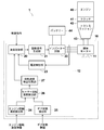
- FIG. 1 is a schematic configuration diagram of an automobile equipped with a retarder according to a first embodiment of the present invention. Graph showing the characteristics of the induction motor mounted on the retarder The schematic block diagram of the motor vehicle carrying the retarder of the 2nd Embodiment of this invention Graph showing the relationship between engine speed and motor speed
- FIG. 1 is a schematic configuration diagram of an automobile equipped with a retarder according to the first embodiment of the present invention
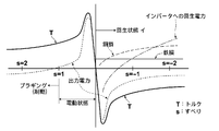
- FIG. 2 is a graph showing characteristics of an induction motor mounted on the retarder.
- the automobile 1 mainly connects / disconnects an engine 40 for driving an axle, a transmission 42 that converts an output rotational speed and torque of the engine 40 by a combination of gears, and a connection between the engine 40 and the transmission 42.
- a retarder 10 for applying braking or torque to the rotation of the main shaft of the engine 40 (the output shaft 43 of the transmission 42) or generating power by rotating the main shaft of the engine 40, and storing electric power -It is comprised by the battery 44 etc. for supply.
- the retarder 10 is capable of any of braking, power generation, and torque generation.
- the induction motor 11 connected to the output shaft 43 of the transmission 42 and the control for controlling the induction motor 11. Part (control means) 12.
- the control unit 12 receives an operation control command from the automobile 1 side (outside the retarder 10) and controls a speed control unit 20 that controls the speed of the induction motor 11, and an inverter circuit 22 described later based on an instruction from the speed control unit 20.
- a drive signal generation unit 21 that generates a drive signal for driving, an inverter circuit 22 for controlling the induction motor 11 and transmitting electric power generated in the induction motor 11 to the battery 44, and the induction motor 11
- a current detector 23 for detecting the amount of current flowing in / out.
- control unit 12 includes an engine rotation speed detection unit 24 that receives information detected by the rotation speed sensor of the engine 40 from the vehicle 1 side (outside the retarder 10), and the transmission 42 from the vehicle 1 side (outside the retarder 10). Based on the gear state detector 25 that receives information indicating the gear state (information indicating the number of gears in the present embodiment), information detected by the rotational speed sensor of the engine 40, and information indicating the gear state of the transmission 42. , The motor rotation speed calculation unit 26 that converts the signal into a form in which the speed control unit 20 can correctly recognize the rotation speed of the induction motor 11, and the rotation speed acquired by the motor rotation speed calculation unit 26 for the speed control unit 20. And a rotation speed detection switching unit 27 for switching whether or not to send a signal.
- engine rotation speed detection unit 24 that receives information detected by the rotation speed sensor of the engine 40 from the vehicle 1 side (outside the retarder 10), and the transmission 42 from the vehicle 1 side (outside the retarder 10). Based on the gear state detector 25 that receives information indicating the gear
- the rotation speed of the induction motor 11 can be acquired.
- the information received by the engine rotation speed detection unit 24 and the gear state detection unit 25 is a digital signal that is flowed in an in-vehicle digital communication system such as a CAN (Controller Area Network) in the automobile 1.
- an in-vehicle digital communication system such as a CAN (Controller Area Network) in the automobile 1.
- the engine rotation speed detection unit 24 and the gear state detection unit 25 are independently shown as a functional block diagram. However, the information detected by the rotation speed sensor of the engine 40 and the transmission 42 are detected by the same signal reception unit. Information indicating the gear state may be received.
- the motor rotation speed calculation unit 26 has information on the reduction ratio at each gear stage in advance, and divides the rotation speed of the engine 40 by the current reduction ratio of the transmission 42 to calculate the rotation speed of the output shaft of the transmission 42. A numerical value is calculated, and based on the numerical value, the speed control unit 20 converts it into a signal form that can correctly recognize the rotation speed of the induction motor 11, and outputs the converted rotation speed signal to the speed control unit 20.
- the speed control unit 20 is based on the rotation speed signal sent from the motor rotation speed calculation unit 26 according to the characteristics of the induction motor as shown in FIG. 2 based on the operation control command from the automobile 1 side (outside the retarder 10). Thus, the slip amount of the induction motor 11 is adjusted, and the induction motor 11 is appropriately controlled.
- the retarder 10 of the present embodiment is capable of any of braking, power generation, and torque generation, and controls the induction motor 11 so that the slip becomes a value larger than 1 during braking. Further, the induction motor 11 is controlled so that the slip is larger than 0 and smaller than 1 at the time of electric assist (torque generation).
- the induction motor 11 is controlled so that the slip becomes a value smaller than zero.
- the slip during the regenerative operation is set in a region where the amount of generated power is close to 0 (a region where the value of the regenerative power indicated by the alternate long and short dash line in FIG. 2 is small in the vertical axis direction). If the storage capacity of the battery 44 becomes full during operation, the regenerative operation cannot be continued. For this reason, when the storage capacity of the battery 44 becomes full during the regenerative operation, the slip is increased in the negative direction, and the power consumption exceeds the regenerative power (the value of the regenerative power indicated by the one-dot chain line in FIG. 2). By shifting to a positive region in the vertical axis direction, the regenerative operation can be continued without interrupting the regenerative operation.
- the rotational speed of the motor can be acquired without mounting a rotational speed sensor on the induction motor 11 itself, so that it is low-cost and accurate sensorless control regardless of the operating state of the motor. Can be performed.
- the clutch is disengaged when the information on the disengagement of the clutch 41 included in the automobile 1 is acquired, when the gear of the transmission 42 is neutral, or when the rotational speed of the engine 40 rapidly increases.
- the gear is in a neutral state and setting the induction motor 11 to be in an uncontrolled state in which all control is stopped, or controlling so that neither driving nor braking torque occurs.
- the retarder 10 can be prevented from falling into a dangerous operating state.
- FIG. 3 is a schematic configuration diagram of an automobile equipped with the retarder according to the second embodiment of the present invention
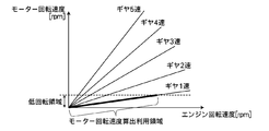
- FIG. 4 is a graph showing the relationship between the engine rotation speed and the motor rotation speed.
- the configuration of the control unit 12 is changed as compared with the first embodiment. Elements that are the same as those in FIG. 1 are given the same reference numerals, and descriptions thereof are omitted unless necessary, and only differences are mainly described.
- the control unit 12 receives an operation control command from the automobile 2 side (outside the retarder 10 ′) and controls the speed of the induction motor 11, and an inverter circuit 22 described later based on an instruction from the speed control unit 20.
- a drive signal generator 21 for generating a drive signal for driving the inverter, an inverter circuit 22 for controlling the induction motor 11 and transmitting the electric power generated in the induction motor 11 to the battery 44, and the induction motor 11.
- a current detector 23 for detecting the amount of current flowing in and out.
- the control unit 12 includes an engine rotation speed detection unit 24 that receives information detected by the rotation speed sensor of the engine 40 from the vehicle 2 side (outside of the retarder 10 ′), and a transmission from the vehicle 2 side (outside of the retarder 10 ′). Based on the information detected by the rotation speed sensor of the engine 40 and the information indicating the gear state of the transmission 42, the speed control unit 20 rotates the induction motor 11 based on the gear state detection unit 25 that receives information indicating the gear state of 42 and the information detected by the rotation speed sensor of the engine 40.
- a motor rotation speed calculation unit 26 that converts a signal into a form in which the speed can be correctly recognized, a vehicle speed detection unit 28 that receives information detected by a vehicle speed sensor included in the vehicle 2 from the vehicle 2 side (outside of the retarder 10 ′), a vehicle speed Based on the information (signal) detected by the sensor, the speed control unit 20 rotates the rotation speed of the induction motor 11.
- the motor rotation speed calculation unit 29 that converts the signal into a form that can be correctly recognized, and the rotation speed signal acquired by the motor rotation speed calculation unit 26 to the speed control unit 20 are sent, or the motor rotation speed calculation unit 29 And a rotation speed detection switching unit 27 for switching whether to transmit the acquired rotation speed signal or not to transmit the rotation speed signal.
- the information received by the engine rotation speed detection unit 24, the gear state detection unit 25, and the vehicle speed detection unit 28 is a digital signal that is sent in an in-vehicle digital communication system such as a CAN (Controller Area Network) in the automobile 2. It is.
- CAN Controller Area Network
- the engine speed detection unit 24, the gear state detection unit 25, and the vehicle speed detection unit 28 are shown independently as a functional block diagram, but the same signal receiving unit detects the rotation speed sensor of the engine 40.
- the received information, the information indicating the gear state of the transmission 42, and the information detected by the vehicle speed sensor may be received.
- the induction motor 11 can be controlled based on the information detected by the vehicle speed sensor.
- the rotation speed of the induction motor 11 (that is, the rotation speed of the output shaft of the transmission 42) is based on the information detected by the rotation speed sensor of the engine 40 and the information indicating the gear state of the transmission 42. It is possible to control the induction motor 11 with a simpler process than deriving.
- a vehicle speed sensor in which a rotation detection sensor such as a resolver is generally used does not have high speed detection accuracy in a low speed (low rotation) region, and therefore there is a possibility that the induction motor cannot be controlled with high accuracy in a low speed region.
- the rotational speed sensor of the engine 40 which is the same sensor as the vehicle speed sensor, is not as accurate in the low-speed region as the vehicle speed sensor.
- the reduction ratio of the transmission 42 is not less than 1, it is higher than the vehicle speed sensor. Since the rotational speed sensor of the engine 40 has a higher rotational speed, the rotational speed of the induction motor 11 is determined based on information detected by the rotational speed sensor of the engine 40 and information indicating the gear state of the transmission 42 in such a state. The derived speed can increase the speed detection accuracy.
- the rotational speed of the engine 40 is higher than the rotational speed of the induction motor 11 (that is, the rotational speed of the output shaft of the transmission 42), especially when the gear is first gear.
- a motor rotational speed calculation unit 26 is switched so that the rotational speed signal (rotational speed signal based on the rotational speed of the engine 40 and the gear state) acquired by the engine 26 is sent to the speed controller 20, and in other states, the motor rotational speed calculator 29 The rotational speed signal (rotational speed signal based on the vehicle speed sensor) acquired by the Then switched to deliver to.
- the rotational speed sensor of the engine 40 Since the rotational speed sensor of the engine 40 has a higher rotational speed than the vehicle speed sensor except for the number of gear stages with a reduction ratio of less than 1, the rotational speed signal of the rotational speed signal based on the vehicle speed sensor is low because the rotational speed of the induction motor 11 is low. In areas where the accuracy is not very high (areas below the dotted line in the graph in FIG. 4), the motor rotation speed is calculated not only for the 1st speed but also for all gear speeds except for the gear speed where the reduction ratio is less than 1.
- the rotation speed signal acquired by the unit 26 (the rotation speed signal based on the rotation speed of the engine 40 and the gear state) may be switched to be sent to the speed control unit 20.
- the speed control unit 20 Based on the operation control command from the automobile 2 side (outside the retarder 10 ′), the speed control unit 20 converts the rotation speed signal sent from the rotation speed detection switching unit 27 according to the characteristics of the induction motor as shown in FIG. Based on this, the slip amount of the induction motor 11 is adjusted, and the induction motor 11 is appropriately controlled.
- the induction motor 11 is used based on information detected by the rotation speed sensor of the engine 40 and information indicating the gear state of the transmission 42. Since the speed detection accuracy can be improved by using the control method, the induction motor 11 can be controlled efficiently.
- information detected by the rotation speed sensor of the engine 40 and information detected by the vehicle speed sensor are received from the vehicle side 1 and 2 (outside of the retarders 10 and 10 ').
- the information is not limited to the digital signal as described above, but may be the output signal itself of each sensor (a so-called rotation pulse signal or vehicle speed pulse signal).
- the received pulse signal may be converted by the speed control unit 20 into a signal that can correctly recognize the rotation speed of the induction motor 11 and output. Note that if the vehicle speed pulse signal has the same form as a signal that allows the speed controller 20 to correctly recognize the rotational speed of the induction motor 11, no conversion is necessary.
Landscapes
- Engineering & Computer Science (AREA)
- Transportation (AREA)
- Mechanical Engineering (AREA)
- Power Engineering (AREA)
- Chemical & Material Sciences (AREA)
- Combustion & Propulsion (AREA)
- Electric Propulsion And Braking For Vehicles (AREA)
- Hybrid Electric Vehicles (AREA)
- Control Of Ac Motors In General (AREA)
Abstract
Priority Applications (2)
| Application Number | Priority Date | Filing Date | Title |
|---|---|---|---|
| KR1020147029658A KR20150004811A (ko) | 2012-04-19 | 2013-04-15 | 리타더 |
| EP13777862.7A EP2840704A4 (fr) | 2012-04-19 | 2013-04-15 | Ralentisseur |
Applications Claiming Priority (2)
| Application Number | Priority Date | Filing Date | Title |
|---|---|---|---|
| JP2012-095472 | 2012-04-19 | ||
| JP2012095472A JP5964641B2 (ja) | 2012-04-19 | 2012-04-19 | リターダ |
Publications (1)
| Publication Number | Publication Date |
|---|---|
| WO2013157239A1 true WO2013157239A1 (fr) | 2013-10-24 |
Family
ID=49383210
Family Applications (1)
| Application Number | Title | Priority Date | Filing Date |
|---|---|---|---|
| PCT/JP2013/002541 WO2013157239A1 (fr) | 2012-04-19 | 2013-04-15 | Ralentisseur |
Country Status (4)
| Country | Link |
|---|---|
| EP (1) | EP2840704A4 (fr) |
| JP (1) | JP5964641B2 (fr) |
| KR (1) | KR20150004811A (fr) |
| WO (1) | WO2013157239A1 (fr) |
Cited By (1)
| Publication number | Priority date | Publication date | Assignee | Title |
|---|---|---|---|---|
| EP3139494A4 (fr) * | 2014-04-16 | 2017-12-20 | TBK Co., Ltd. | Système de moteur à résonance |
Families Citing this family (1)
| Publication number | Priority date | Publication date | Assignee | Title |
|---|---|---|---|---|
| JP6068560B2 (ja) * | 2015-06-03 | 2017-01-25 | 株式会社シマノ | 自転車用制御装置 |
Citations (7)
| Publication number | Priority date | Publication date | Assignee | Title |
|---|---|---|---|---|
| JPH0424156A (ja) * | 1990-05-18 | 1992-01-28 | Hino Motors Ltd | 自動車の電気制動および補助加速装置 |
| JPH0438200A (ja) * | 1990-05-31 | 1992-02-07 | Hino Motors Ltd | 自動車の電気制動および補助加速装置 |
| JPH04328024A (ja) * | 1991-04-26 | 1992-11-17 | Hino Motors Ltd | 自動車の補助制動加速装置 |
| JPH08126118A (ja) | 1987-02-18 | 1996-05-17 | Hino Motors Ltd | 電気制動装置 |
| JPH0968064A (ja) * | 1995-08-31 | 1997-03-11 | Hino Motors Ltd | エンジンの自動停止始動装置 |
| JPH1022509A (ja) | 1996-06-28 | 1998-01-23 | Omron Corp | センサ装置 |
| JP2010163872A (ja) * | 2009-01-13 | 2010-07-29 | Denso Corp | 内燃機関の始動停止制御装置及び回転機の制御装置 |
Family Cites Families (16)
| Publication number | Priority date | Publication date | Assignee | Title |
|---|---|---|---|---|
| JP3607960B2 (ja) * | 1996-02-14 | 2005-01-05 | トヨタ自動車株式会社 | モータ制御装置及び制御方法 |
| EP1018451B1 (fr) * | 1998-07-21 | 2007-11-28 | TOKYO R & D Co., Ltd. | Vehicule hybride et procede de gestion du deplacement du vehicule |
| JP3542932B2 (ja) * | 1999-08-04 | 2004-07-14 | 本田技研工業株式会社 | ハイブリッド車両の減速回生/充電の許可判定方法および装置 |
| JP3824821B2 (ja) * | 1999-10-08 | 2006-09-20 | 本田技研工業株式会社 | ハイブリッド車両の回生制御装置 |
| JP3656242B2 (ja) * | 1999-10-26 | 2005-06-08 | スズキ株式会社 | 車両のモータ制御装置 |
| US6543588B1 (en) * | 2000-02-02 | 2003-04-08 | Pacific Scientific-Electro Kinetics Division | Integrated retarder and accessory device |
| JP3485905B2 (ja) * | 2001-04-26 | 2004-01-13 | 本田技研工業株式会社 | モータ制御装置 |
| US6750626B2 (en) * | 2002-09-11 | 2004-06-15 | Ford Global Technologies, Llc | Diagnostic strategy for an electric motor using sensorless control and a position sensor |
| JP3777165B2 (ja) * | 2003-02-25 | 2006-05-24 | 日野自動車株式会社 | ハイブリッド自動車 |
| JP4230276B2 (ja) * | 2003-05-19 | 2009-02-25 | 本田技研工業株式会社 | ブラシレスdcモータの制御装置 |
| JP4609069B2 (ja) * | 2004-12-27 | 2011-01-12 | 日産自動車株式会社 | 電気車両の充放電制御装置 |
| JP4192992B2 (ja) * | 2007-02-15 | 2008-12-10 | トヨタ自動車株式会社 | 動力出力装置及びその動力出力装置を搭載したハイブリッド車 |
| JP5131051B2 (ja) * | 2008-06-23 | 2013-01-30 | 株式会社デンソー | 回転機の制御装置、及び回転機の制御システム |
| JP5412845B2 (ja) * | 2009-01-23 | 2014-02-12 | 日産自動車株式会社 | 車両用モータ制御装置及びその方法 |
| JP5240004B2 (ja) * | 2009-03-30 | 2013-07-17 | アイシン精機株式会社 | 車両制御装置 |
| US8535201B2 (en) * | 2010-09-30 | 2013-09-17 | Ford Global Technologies, Llc | Method and strategy to detect the lock-up of planetary gear in power split hybrid vehicles |
-
2012
- 2012-04-19 JP JP2012095472A patent/JP5964641B2/ja active Active
-
2013
- 2013-04-15 WO PCT/JP2013/002541 patent/WO2013157239A1/fr active Application Filing
- 2013-04-15 EP EP13777862.7A patent/EP2840704A4/fr not_active Withdrawn
- 2013-04-15 KR KR1020147029658A patent/KR20150004811A/ko not_active Application Discontinuation
Patent Citations (7)
| Publication number | Priority date | Publication date | Assignee | Title |
|---|---|---|---|---|
| JPH08126118A (ja) | 1987-02-18 | 1996-05-17 | Hino Motors Ltd | 電気制動装置 |
| JPH0424156A (ja) * | 1990-05-18 | 1992-01-28 | Hino Motors Ltd | 自動車の電気制動および補助加速装置 |
| JPH0438200A (ja) * | 1990-05-31 | 1992-02-07 | Hino Motors Ltd | 自動車の電気制動および補助加速装置 |
| JPH04328024A (ja) * | 1991-04-26 | 1992-11-17 | Hino Motors Ltd | 自動車の補助制動加速装置 |
| JPH0968064A (ja) * | 1995-08-31 | 1997-03-11 | Hino Motors Ltd | エンジンの自動停止始動装置 |
| JPH1022509A (ja) | 1996-06-28 | 1998-01-23 | Omron Corp | センサ装置 |
| JP2010163872A (ja) * | 2009-01-13 | 2010-07-29 | Denso Corp | 内燃機関の始動停止制御装置及び回転機の制御装置 |
Non-Patent Citations (1)
| Title |
|---|
| See also references of EP2840704A4 * |
Cited By (1)
| Publication number | Priority date | Publication date | Assignee | Title |
|---|---|---|---|---|
| EP3139494A4 (fr) * | 2014-04-16 | 2017-12-20 | TBK Co., Ltd. | Système de moteur à résonance |
Also Published As
| Publication number | Publication date |
|---|---|
| JP2013223399A (ja) | 2013-10-28 |
| EP2840704A4 (fr) | 2016-06-01 |
| JP5964641B2 (ja) | 2016-08-03 |
| EP2840704A1 (fr) | 2015-02-25 |
| KR20150004811A (ko) | 2015-01-13 |
Similar Documents
| Publication | Publication Date | Title |
|---|---|---|
| US8125169B2 (en) | Rotating electrical machine control system and vehicle drive system | |
| US7482769B2 (en) | Control apparatus for electric motor and abnormality detection method for electric motor control | |
| KR101558812B1 (ko) | 하이브리드 차량의 타행 주행시 모터 토크 제어 방법 | |
| EP2873576B1 (fr) | Dispositif de commande d'un véhicule hybride et procédé de commande d'un véhicule hybride | |
| JP4839960B2 (ja) | 車両用動力装置およびその制御装置 | |
| JP5964641B2 (ja) | リターダ | |
| JP4419996B2 (ja) | スリップ判定装置およびスリップ判定方法 | |
| JP4816243B2 (ja) | 車両用動力装置およびその制御装置 | |
| US9272697B2 (en) | Limiting regenerative torque for a hybrid electric powertrain | |
| JP2009153281A (ja) | 電動車両の制御装置 | |
| WO2007107091A1 (fr) | Compensateur de puissance de changement de vitesse | |
| JP2009077572A (ja) | 電気車制御装置 | |
| JP4797537B2 (ja) | モーター制御装置 | |
| WO2013157240A1 (fr) | Ralentisseur | |
| JP2011172324A (ja) | インバータ制御装置 | |
| KR102555514B1 (ko) | 병렬형 하이브리드 차량의 모터 제어 장치 및 그것의 모터 고장 진단 방법 | |
| JP6381723B1 (ja) | 回転電機の制御装置および制御方法 | |
| US9236816B2 (en) | Method for starting a synchronous machine | |
| JP3620137B2 (ja) | 電気自動車の補機駆動装置及び補機駆動方法 | |
| WO2021166418A1 (fr) | Dispositif de commande de véhicule | |
| JP7376323B2 (ja) | 制動制御装置 | |
| WO2023281560A1 (fr) | Dispositif de commande d'entraînement de véhicule électrique | |
| JP2014008883A (ja) | 車両駆動機構 | |
| JP2012091647A (ja) | ブレーキの診断装置 | |
| JP5397033B2 (ja) | エンジン始動装置 |
Legal Events
| Date | Code | Title | Description |
|---|---|---|---|
| 121 | Ep: the epo has been informed by wipo that ep was designated in this application |
Ref document number: 13777862 Country of ref document: EP Kind code of ref document: A1 |
|
| NENP | Non-entry into the national phase |
Ref country code: DE |
|
| ENP | Entry into the national phase |
Ref document number: 20147029658 Country of ref document: KR Kind code of ref document: A |
|
| REEP | Request for entry into the european phase |
Ref document number: 2013777862 Country of ref document: EP |
|
| WWE | Wipo information: entry into national phase |
Ref document number: 2013777862 Country of ref document: EP |