誘導モーターのコストを低減させるために、回転速度センサーを不要とするセンサーレス制御が提案されている。
In order to reduce the cost of induction motors, sensorless control that eliminates the need for a rotational speed sensor has been proposed.
従来提案されているセンサーレス制御の原理は、ローターに対して所定の回転速度で回転させるように制御した場合にステーターで発生する誘起起電力の理論値と実際値との乖離を検出し、この乖離の量に基づいて回転速度の指令値を制御することで、ローターの回転速度の推定およびローターの回転速度制御を行うものである。
The principle of sensorless control that has been proposed in the past is to detect the difference between the theoretical value and the actual value of the induced electromotive force generated in the stator when the rotor is controlled to rotate at a predetermined rotational speed. By controlling the rotational speed command value based on the amount of deviation, the rotational speed of the rotor is estimated and the rotational speed of the rotor is controlled.
ただし、この方法では、ローターが停止している状態から回転速度制御を行う場合には原理通りの制御を行うことができるが、ローターが回転している状態から回転速度制御を行う場合には、制御時のローターの動作状態により上記乖離量が過大となり安定した制御が困難となるため、原理通りの制御を行うことができない。
However, in this method, when the rotational speed control is performed from the state where the rotor is stopped, the control according to the principle can be performed, but when the rotational speed control is performed from the state where the rotor is rotating, According to the operating state of the rotor at the time of control, the divergence amount becomes excessive and stable control becomes difficult, so that the control according to the principle cannot be performed.
本発明は、上記問題に鑑みてなされたものであり、誘導モーターを備えたリターダにおいて、モーターの動作状態に関わらず正確なセンサーレス制御が可能なリターダを提供することを目的とするものである。
The present invention has been made in view of the above problems, and an object of the present invention is to provide a retarder including an induction motor that can perform accurate sensorless control regardless of the operation state of the motor. .
本発明のリターダは、内燃機関によりトランスミッションを介して車軸が駆動される自動車に用いられるリターダであって、トランスミッションの出力軸と連結される誘導モーターと、自動車が備える内燃機関の回転速度センサーが検出した情報および自動車から取得したトランスミッションのギア状態を示す情報に基づいて誘導モーターの回転速度を導出し、導出した回転速度に基づいて誘導モーターを制御する制御手段とを備えてなることを特徴とする。
The retarder of the present invention is a retarder used in an automobile in which an axle is driven by an internal combustion engine via a transmission, and is detected by an induction motor connected to the output shaft of the transmission and a rotation speed sensor of the internal combustion engine provided in the automobile. Control means for deriving the rotation speed of the induction motor based on the obtained information and information indicating the gear state of the transmission acquired from the vehicle, and for controlling the induction motor based on the derived rotation speed. .
本発明のリターダにおいてトランスミッションは、MT(Manual Transmission)、AT(Automatic Transmission)、CVT(Continuously Variable Transmission)等、どのような形態のトランスミッションでもよい。
In the retarder of the present invention, the transmission may be any type of transmission such as MT (Manual Transmission), AT (Automatic Transmission), CVT (Continuously Variable Transmission).
ここで、「内燃機関(エンジン)の回転速度センサーが検出した情報」とは、エンジン回転速度センサーの出力信号そのもの(例えば、いわゆる回転パルス信号と呼ばれる信号)や、CAN(Controller Area Network)等の車内デジタル通信システムにおいて流されるエンジン回転速度に対応したデジタル信号等、エンジン回転速度に対応した信号であればどのようなものでもよい。
Here, “information detected by the rotational speed sensor of the internal combustion engine (engine)” means an output signal of the engine rotational speed sensor itself (for example, a signal called a so-called rotational pulse signal), CAN (Controller Area Network), or the like. Any signal corresponding to the engine rotation speed such as a digital signal corresponding to the engine rotation speed that is flowed in the in-vehicle digital communication system may be used.
また、「ギア状態を示す情報」とは、ギア段数(ニュートラルを含む)の情報の他、トランスミッションの現在の減速比を示す情報等、最終的にトランスミッションにおける減速比を特定できる情報であればどのような形態でもよい。なお、制御手段においてギア段数のみを自動車側から取得する場合には、各ギア段数における減速比の情報は予め取得しておく必要がある。
The “information indicating the gear state” is information that can finally specify the reduction ratio in the transmission, such as information on the number of gears (including neutral), information indicating the current reduction ratio of the transmission, and the like. Such a form may be sufficient. In addition, when acquiring only the gear stage number from the vehicle side in the control means, it is necessary to previously acquire information on the reduction ratio at each gear stage number.
また、「内燃機関の回転速度センサーが検出した情報および自動車から取得したトランスミッションのギア状態を示す情報に基づいて誘導モーターの回転速度を導出する」とは、例えば内燃機関の回転速度をトランスミッションの減速比で除算する等して、トランスミッションの出力軸の回転速度に比例する速度情報を取得することを意味する。
“Deriving the rotational speed of the induction motor based on the information detected by the rotational speed sensor of the internal combustion engine and the information indicating the gear state of the transmission acquired from the automobile” means, for example, that the rotational speed of the internal combustion engine is decelerated from the transmission. It means that speed information proportional to the rotational speed of the output shaft of the transmission is obtained by dividing by the ratio.
本発明のリターダにおいては、自動車が備えるクラッチが切断されていたりギアがニュートラルの状態になっていたりして、内燃機関とトランスミッションの出力軸との間で駆動力が伝達されていない状態では、誘導モーターの回転速度を正確に導出することが難しい。従って、制御手段は、内燃機関の回転速度の単位時間当たりの変化量が所定の閾値を超えた場合、すなわち内燃機関の回転数が急激に上昇した場合には、クラッチが切断された状態もしくはギアがニュートラルの状態とみなして、誘導モーターに対して一切の制御を停止した無制御状態とするか、駆動・制動トルクとも生じぬように制御するものとしてもよい。
In the retarder according to the present invention, when the clutch included in the automobile is disengaged or the gear is in a neutral state and the driving force is not transmitted between the internal combustion engine and the output shaft of the transmission, induction is performed. It is difficult to accurately derive the rotation speed of the motor. Therefore, when the amount of change in the rotational speed of the internal combustion engine per unit time exceeds a predetermined threshold value, that is, when the rotational speed of the internal combustion engine suddenly increases, the control means is in a state where the clutch is disengaged or the gear. May be regarded as a neutral state, and the induction motor may be in an uncontrolled state in which all control is stopped, or may be controlled so that neither driving nor braking torque is generated.
また、制御手段は、自動車が備えるクラッチが切断された情報を取得した場合や、トランスミッションのギアがニュートラルである場合に、誘導モーターに対して一切の制御を停止した無制御状態とするか、駆動・制動トルクとも生じぬように制御するものとしてもよい。
In addition, the control means, when acquiring information that the clutch provided in the car is disengaged, or when the transmission gear is neutral, puts the control in an uncontrolled state in which all control on the induction motor is stopped, or drives -It is good also as what controls so that braking torque does not arise.
自動車が備える車速センサーは一般的にトランスミッションの出力軸の回転速度を検出するものであるため、車速センサーが検出した情報に基づいても誘導モーターを制御することが可能であり、この場合には内燃機関の回転速度センサーが検出した情報およびトランスミッションのギア状態を示す情報に基づいて誘導モーターの回転速度(すなわちトランスミッションの出力軸の回転速度)を導出するよりも簡単な処理で誘導モーターの制御を行うことが可能である。
Since a vehicle speed sensor provided in an automobile generally detects the rotational speed of the output shaft of the transmission, the induction motor can be controlled based on information detected by the vehicle speed sensor. The induction motor is controlled by a simpler process than deriving the rotation speed of the induction motor (that is, the rotation speed of the output shaft of the transmission) based on information detected by the engine rotation speed sensor and information indicating the gear state of the transmission. It is possible.
しかしながら、タコジェネレーター等の回転検出センサーが一般的に用いられる車速センサーは、低速(低回転)領域では速度検出精度が高くないため、低速領域では高精度に誘導モーターを制御できないおそれがある。車速センサーと同様のセンサーである内燃機関の回転速度センサーも、車速センサーと同様に低回転領域では速度検出精度は高くないが、トランスミッションの減速比が1未満とならない限りは、車速センサーよりも内燃機関の回転速度センサーの方が高い回転速度となるため、このような状態では内燃機関の回転速度センサーが検出した情報およびトランスミッションのギア状態を示す情報に基づいて誘導モーターの回転速度を導出した方が、速度検出精度を高くすることができる。
However, a vehicle speed sensor that uses a rotation detection sensor such as a tachometer generator generally does not have high speed detection accuracy in a low speed (low rotation) region, and therefore may not be able to control the induction motor with high accuracy in a low speed region. The speed sensor of the internal combustion engine, which is the same sensor as the vehicle speed sensor, is not as accurate in the low speed range as the vehicle speed sensor, but it is more internal than the vehicle speed sensor unless the transmission reduction ratio is less than 1. Since the engine speed sensor has a higher speed, in this state, the speed of the induction motor is derived based on information detected by the engine speed sensor and information indicating the transmission gear state. However, the speed detection accuracy can be increased.
従って、制御手段は、自動車が備える車速センサーが検出した情報に基づいて誘導モーターを制御する機能をさらに備え、車速センサーが検出した情報およびトランスミッションのギア状態を示す情報のうち少なくとも一つの情報に基づいて、回転速度センサーが検出した情報およびトランスミッションのギア状態を示す情報に基づいて誘導モーターを制御するか、車速センサーが検出した情報に基づいて誘導モーターを制御するかを切り替えるものとしてもよい。
Therefore, the control means further includes a function of controlling the induction motor based on information detected by a vehicle speed sensor included in the automobile, and is based on at least one information among information detected by the vehicle speed sensor and information indicating a gear state of the transmission. Thus, the induction motor may be controlled based on the information detected by the rotation speed sensor and the information indicating the gear state of the transmission, or the induction motor may be controlled based on the information detected by the vehicle speed sensor.
ここで、「自動車が備える車速センサーが検出した情報」とは、車速センサーの出力信号そのもの(例えば、いわゆる車速パルス信号と呼ばれる信号)や、CAN(Controller Area Network)等の車内デジタル通信システムにおいて流される車速に対応したデジタル信号等、車速に対応した信号であればどのようなものでもよい。
Here, the “information detected by the vehicle speed sensor included in the automobile” refers to the output signal itself of the vehicle speed sensor (for example, a signal called a so-called vehicle speed pulse signal) or in-vehicle digital communication systems such as CAN (Controller Area Network). Any signal corresponding to the vehicle speed, such as a digital signal corresponding to the vehicle speed, can be used.
また、「車速センサーが検出した情報に基づいて誘導モーターを制御する」とは、上記の情報に基づいて誘導モーターを制御することを意味し、例えば、車速パルス信号に基づいて誘導モーターを制御する場合、通常車速センサーは誘導モーターと連結されるトランスミッションの出力軸の回転速度を検出するものであるため、リターダの制御回路(制御手段)が、誘導モーターに従来備わっていたレゾルバ等の回転速度センサーの出力信号に基づいて誘導モーターを制御するように構成されているとともに、誘導モーターが従来備える回転速度センサーの出力信号と車速パルス信号が同等の信号である場合には、受信した車速パルス信号を回転速度センサーの出力信号とみなして、従来の誘導モーターの制御回路をそのまま利用することができる。
Further, “controlling the induction motor based on the information detected by the vehicle speed sensor” means controlling the induction motor based on the above information, for example, controlling the induction motor based on the vehicle speed pulse signal. In this case, since the normal vehicle speed sensor detects the rotational speed of the output shaft of the transmission connected to the induction motor, the retarder control circuit (control means) is a rotational speed sensor such as a resolver conventionally provided in the induction motor. The induction motor is controlled based on the output signal of the vehicle, and when the output signal of the rotational speed sensor conventionally provided in the induction motor and the vehicle speed pulse signal are equivalent signals, the received vehicle speed pulse signal is Use the control circuit of the conventional induction motor as it is, considering it as the output signal of the rotation speed sensor It can be.
また、リターダの制御回路(制御手段)が、誘導モーターに従来備わっていた回転速度センサーの出力信号に基づいて誘導モーターを制御するように構成されている場合であっても、誘導モーターが従来備える回転速度センサーの出力信号と車速パルス信号が異なる信号である場合や、CAN(Controller Area Network)等の車内デジタル通信システムにおいて流される車速に対応したデジタル信号を受信する場合には、受信した信号を誘導モーターの制御回路における誘導モーターの回転速度を示す信号と対応させるように変換する必要がある。
Further, even when the retarder control circuit (control means) is configured to control the induction motor based on the output signal of the rotation speed sensor that is conventionally provided in the induction motor, the induction motor is conventionally provided. When the output signal of the rotational speed sensor is different from the vehicle speed pulse signal, or when receiving a digital signal corresponding to the vehicle speed that is flowed in the in-vehicle digital communication system such as CAN (Controller Area Network), the received signal is It is necessary to perform conversion so as to correspond to a signal indicating the rotation speed of the induction motor in the control circuit of the induction motor.
従って、この場合、制御手段は、車速センサーが検出した情報に基づいて誘導モーターの回転速度を導出し、導出した回転速度に基づいて誘導モーターを制御するものとしてもよい。
Therefore, in this case, the control means may derive the rotation speed of the induction motor based on the information detected by the vehicle speed sensor, and control the induction motor based on the derived rotation speed.
本発明の制御方法は、内燃機関によりトランスミッションを介して車軸が駆動される自動車に用いられるリターダにおける、トランスミッションの出力軸と連結される誘導モーターの制御方法であって、自動車が備える内燃機関の回転速度センサーが検出した情報および自動車から取得したトランスミッションのギア状態を示す情報に基づいて誘導モーターの回転速度を導出し、導出した回転速度に基づいて誘導モーターを制御することを特徴とする。
The control method of the present invention is a method for controlling an induction motor connected to an output shaft of a transmission in a retarder used in an automobile in which an axle is driven via a transmission by an internal combustion engine, the rotation of the internal combustion engine provided in the automobile The rotational speed of the induction motor is derived based on information detected by the speed sensor and information indicating the gear state of the transmission acquired from the vehicle, and the induction motor is controlled based on the derived rotational speed.
本発明の制御方法においては、内燃機関の回転速度の単位時間当たりの変化量が所定の閾値を超えた場合に、誘導モーターに対して、一切の制御を停止した無制御状態とするか、駆動・制動トルクとも生じぬように制御してもよい。
In the control method of the present invention, when the amount of change in the rotational speed of the internal combustion engine per unit time exceeds a predetermined threshold, the induction motor is brought into an uncontrolled state in which all control is stopped or driven. -You may control so that neither braking torque will arise.
また、自動車が備えるクラッチが切断された情報を取得した場合や、トランスミッションのギアがニュートラルである場合に、誘導モーターに対して、一切の制御を停止した無制御状態とするか、駆動・制動トルクとも生じぬように制御してもよい。
In addition, when the information on the clutch of the vehicle is disengaged, or when the transmission gear is neutral, the induction motor is put into an uncontrolled state in which all control is stopped, or the driving / braking torque You may control so that neither may arise.
また、自動車が備える車速センサーが検出した情報をさらに取得し、車速センサーが検出した情報およびトランスミッションのギア状態を示す情報のうち少なくとも一つの情報に基づいて、回転速度センサーが検出した情報およびトランスミッションのギア状態を示す情報に基づいて誘導モーターを制御するか、車速センサーが検出した情報に基づいて誘導モーターを制御するかを切り替えるようにしてもよい。
Further, the information detected by the vehicle speed sensor included in the automobile is further acquired, and the information detected by the rotational speed sensor and the information on the transmission are based on at least one of the information detected by the vehicle speed sensor and the information indicating the gear state of the transmission. You may make it switch whether an induction motor is controlled based on the information which shows a gear state, or an induction motor is controlled based on the information which the vehicle speed sensor detected.
この場合、車速センサーが検出した情報に基づいて誘導モーターの回転速度を導出し、導出した回転速度に基づいて誘導モーターを制御してもよい。
In this case, the rotation speed of the induction motor may be derived based on information detected by the vehicle speed sensor, and the induction motor may be controlled based on the derived rotation speed.
本発明のリターダおよび制御方法によれば、自動車が備える内燃機関の回転速度センサーが検出した情報および自動車から取得したトランスミッションのギア状態を示す情報に基づいて誘導モーターの回転速度を導出し、導出した回転速度に基づいて誘導モーターを制御するようにして、誘導モーターに回転速度センサーを搭載しなくてもモーターの回転速度を取得できるようにしたので、低コストであり、かつモーターの動作状態に関わらず正確なセンサーレス制御を行うことが可能となる。なお、本発明のリターダは、搭載する車種を問わず、どのような車種に対しても適用することが可能である。
According to the retarder and the control method of the present invention, the rotational speed of the induction motor is derived based on the information detected by the rotational speed sensor of the internal combustion engine provided in the automobile and the information indicating the gear state of the transmission acquired from the automobile. Since the induction motor is controlled based on the rotation speed so that the rotation speed of the induction motor can be acquired without mounting a rotation speed sensor on the induction motor, the cost is low and the operation state of the motor is affected. Therefore, accurate sensorless control can be performed. The retarder of the present invention can be applied to any vehicle type regardless of the vehicle type to be mounted.
また、内燃機関の回転速度の単位時間当たりの変化量が所定の閾値を超えた場合、すなわち内燃機関の回転数が急激に上昇した場合には、クラッチが切断された状態もしくはギアがニュートラルの状態とみなして、誘導モーターに対して一切の制御を停止した無制御状態とするか、駆動・制動トルクとも生じぬように制御することにより、不正確な情報に基づいてリターダが危険な動作状態に陥るのを防止することができる。
Further, when the amount of change in the rotational speed of the internal combustion engine per unit time exceeds a predetermined threshold value, that is, when the rotational speed of the internal combustion engine suddenly increases, the clutch is disengaged or the gear is in the neutral state. As a result, the retarder is put into a dangerous operating state based on inaccurate information by setting the induction motor to an uncontrolled state in which all control is stopped or controlling so that neither driving nor braking torque occurs. It can be prevented from falling.
また、自動車が備えるクラッチが切断された情報を取得した場合や、トランスミッションのギアがニュートラルである場合に、誘導モーターに対して一切の制御を停止した無制御状態とするか、駆動・制動トルクとも生じぬように制御するようにしても、上記と同様の効果を得ることができる。
In addition, when information is obtained that the clutch of the car is disengaged, or when the gear of the transmission is neutral, the induction motor is put into an uncontrolled state in which all control is stopped, or both driving and braking torque Even if it is controlled so as not to occur, the same effect as described above can be obtained.
また、自動車が備える車速センサーが検出した情報をさらに取得し、車速センサーが検出した情報およびトランスミッションのギア状態を示す情報のうち少なくとも一つの情報に基づいて、回転速度センサーが検出した情報およびトランスミッションのギア状態を示す情報に基づいて誘導モーターを制御するか、車速センサーが検出した情報に基づいて誘導モーターを制御するかを切り替えるようにすれば、処理が簡単である車速センサーが検出した情報に基づいて誘導モーターを制御する方法を用いて誘導モーターを制御しつつ、速度検出精度が低下する低速(低回転)領域では、回転速度センサーが検出した情報およびトランスミッションのギア状態を示す情報に基づいて誘導モーターを制御する方法を用いて、速度検出精度を向上させることができるので、効率的に誘導モーターを制御することが可能となる。
Further, the information detected by the vehicle speed sensor included in the automobile is further acquired, and the information detected by the rotational speed sensor and the information on the transmission are based on at least one of the information detected by the vehicle speed sensor and the information indicating the gear state of the transmission. By switching between controlling the induction motor based on the information indicating the gear state or controlling the induction motor based on the information detected by the vehicle speed sensor, the process is based on the information detected by the vehicle speed sensor. In the low-speed (low-rotation) region where the speed detection accuracy decreases while controlling the induction motor using the method of controlling the induction motor, guidance is performed based on information detected by the rotational speed sensor and information indicating the gear state of the transmission. Speed detection accuracy is improved by using a motor control method. Since it is Rukoto, it becomes possible to control efficiently induction motor.
この場合、車速センサーが検出した情報に基づいて誘導モーターの回転速度を導出し、導出した回転速度に基づいて誘導モーターを制御するようにすれば、自動車側から受信した信号の態様と、誘導モーターの制御回路(制御手段)における誘導モーターの回転速度を示す信号の態様とが一致しない場合であっても、正確に誘導モーターを制御することが可能となる。
In this case, if the rotational speed of the induction motor is derived based on the information detected by the vehicle speed sensor, and the induction motor is controlled based on the derived rotational speed, the mode of the signal received from the vehicle side and the induction motor Even when the control signal (control means) of the control circuit (control means) does not match the signal mode indicating the rotational speed of the induction motor, the induction motor can be accurately controlled.
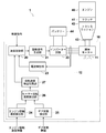
以下、図面を参照して本発明のリターダの第1の実施の形態について詳細に説明する。図1は本発明の第1の実施の形態のリターダを搭載した自動車の概略構成図、図2は上記リターダに搭載された誘導モーターの特性を示すグラフである。
Hereinafter, a first embodiment of the retarder of the present invention will be described in detail with reference to the drawings. FIG. 1 is a schematic configuration diagram of an automobile equipped with a retarder according to the first embodiment of the present invention, and FIG. 2 is a graph showing characteristics of an induction motor mounted on the retarder.
自動車1は、主として車軸を駆動するためのエンジン40と、エンジン40の出力回転速度とトルクを歯車の組み合わせにより変換するトランスミッション42と、エンジン40とトランスミッション42との間の接続を結合/分離するためのクラッチ41と、エンジン40の主軸(トランスミッション42の出力軸43)の回転に対して制動もしくはトルクの印加を行ったり、エンジン40の主軸の回転により発電を行うためのリターダ10と、電力を蓄電・供給するためのバッテリー44等により構成されている。
The automobile 1 mainly connects / disconnects an engine 40 for driving an axle, a transmission 42 that converts an output rotational speed and torque of the engine 40 by a combination of gears, and a connection between the engine 40 and the transmission 42. And a retarder 10 for applying braking or torque to the rotation of the main shaft of the engine 40 (the output shaft 43 of the transmission 42) or generating power by rotating the main shaft of the engine 40, and storing electric power -It is comprised by the battery 44 etc. for supply.
本実施の形態のリターダ10は、制動、発電、トルクの発生のいずれも可能なものであって、トランスミッション42の出力軸43と連結した誘導モーター11と、この誘導モーター11を制御するための制御部(制御手段)12から構成されている。
The retarder 10 according to the present embodiment is capable of any of braking, power generation, and torque generation. The induction motor 11 connected to the output shaft 43 of the transmission 42 and the control for controlling the induction motor 11. Part (control means) 12.
制御部12は、自動車1側(リターダ10外部)から動作制御指令を受けて誘導モーター11の速度制御を行う速度制御部20と、速度制御部20からの指示に基づいて後述のインバーター回路22を駆動するための駆動信号を生成する駆動信号生成部21と、誘導モーター11の制御を行ったり誘導モーター11において発電した電力をバッテリー44へ送出するためのインバーター回路22と、誘導モーター11に対して流入・流出する電流量を検出する電流検出部23とを備えている。
The control unit 12 receives an operation control command from the automobile 1 side (outside the retarder 10) and controls a speed control unit 20 that controls the speed of the induction motor 11, and an inverter circuit 22 described later based on an instruction from the speed control unit 20. A drive signal generation unit 21 that generates a drive signal for driving, an inverter circuit 22 for controlling the induction motor 11 and transmitting electric power generated in the induction motor 11 to the battery 44, and the induction motor 11 And a current detector 23 for detecting the amount of current flowing in / out.
また、制御部12は、自動車1側(リターダ10外部)からエンジン40の回転速度センサーが検出した情報を受信するエンジン回転速度検出部24と、同じく自動車1側(リターダ10外部)からトランスミッション42のギア状態を示す情報(本実施の形態においてはギア段数を示す情報)を受信するギア状態検出部25と、エンジン40の回転速度センサーが検出した情報およびトランスミッション42のギア状態を示す情報に基づいて、速度制御部20が誘導モーター11の回転速度を正しく認識できる形態に信号の変換を行うモーター回転速度算出部26と、速度制御部20に対してモーター回転速度算出部26により取得された回転速度信号を送出するか否かを切り替える回転速度検出切換部27とを備えている。
In addition, the control unit 12 includes an engine rotation speed detection unit 24 that receives information detected by the rotation speed sensor of the engine 40 from the vehicle 1 side (outside the retarder 10), and the transmission 42 from the vehicle 1 side (outside the retarder 10). Based on the gear state detector 25 that receives information indicating the gear state (information indicating the number of gears in the present embodiment), information detected by the rotational speed sensor of the engine 40, and information indicating the gear state of the transmission 42. , The motor rotation speed calculation unit 26 that converts the signal into a form in which the speed control unit 20 can correctly recognize the rotation speed of the induction motor 11, and the rotation speed acquired by the motor rotation speed calculation unit 26 for the speed control unit 20. And a rotation speed detection switching unit 27 for switching whether or not to send a signal.
誘導モーター11のローターはトランスミッション42の出力軸43と結合しており、誘導モーター11の回転速度と出力軸43の回転速度は同じであるため、エンジン40の回転速度センサーが検出した情報およびトランスミッション42のギア状態を示す情報に基づいて出力軸43の回転速度を算出することにより、誘導モーター11の回転速度を取得することが可能である。
Since the rotor of the induction motor 11 is coupled to the output shaft 43 of the transmission 42 and the rotational speed of the induction motor 11 and the rotational speed of the output shaft 43 are the same, the information detected by the rotational speed sensor of the engine 40 and the transmission 42 By calculating the rotation speed of the output shaft 43 based on the information indicating the gear state, the rotation speed of the induction motor 11 can be acquired.
本実施の形態において、エンジン回転速度検出部24およびギア状態検出部25が受信する情報は、自動車1内のCAN(Controller Area Network)等の車内デジタル通信システムにおいて流されるデジタル信号である。
In the present embodiment, the information received by the engine rotation speed detection unit 24 and the gear state detection unit 25 is a digital signal that is flowed in an in-vehicle digital communication system such as a CAN (Controller Area Network) in the automobile 1.
なお、図1では機能ブロック図としてエンジン回転速度検出部24とギア状態検出部25とを独立して示しているが、同一の信号受信部でエンジン40の回転速度センサーが検出した情報およびトランスミッション42のギア状態を示す情報を受信するようにしてもよい。
In FIG. 1, the engine rotation speed detection unit 24 and the gear state detection unit 25 are independently shown as a functional block diagram. However, the information detected by the rotation speed sensor of the engine 40 and the transmission 42 are detected by the same signal reception unit. Information indicating the gear state may be received.
モーター回転速度算出部26は、各ギア段数における減速比の情報を予め有しており、エンジン40の回転速度をトランスミッション42の現在の減速比で除算して、トランスミッション42の出力軸の回転速度の数値を算出し、その数値に基づいて速度制御部20が正しく誘導モーター11の回転速度を認識できる信号の形態に変換し、変換した回転速度信号を速度制御部20に出力する。
The motor rotation speed calculation unit 26 has information on the reduction ratio at each gear stage in advance, and divides the rotation speed of the engine 40 by the current reduction ratio of the transmission 42 to calculate the rotation speed of the output shaft of the transmission 42. A numerical value is calculated, and based on the numerical value, the speed control unit 20 converts it into a signal form that can correctly recognize the rotation speed of the induction motor 11, and outputs the converted rotation speed signal to the speed control unit 20.
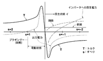
速度制御部20は、自動車1側(リターダ10外部)からの動作制御指令に基づいて、図2に示すような誘導モーターの特性に従い、モーター回転速度算出部26から送出された回転速度信号に基づいて誘導モーター11のすべり量を調整し、誘導モーター11の適切な制御を行う。
The speed control unit 20 is based on the rotation speed signal sent from the motor rotation speed calculation unit 26 according to the characteristics of the induction motor as shown in FIG. 2 based on the operation control command from the automobile 1 side (outside the retarder 10). Thus, the slip amount of the induction motor 11 is adjusted, and the induction motor 11 is appropriately controlled.
ここで「すべり」とは、同期速度NS(rpm)と実際の回転速度N(rpm)との差である相対速度と、同期速度NSとの比であり、下記(1)式で表される。
s=(NS-N)/NS ・・(1)
Here, the "slip" is a relative speed which is the difference between the synchronous speed N S (rpm) and the actual rotational speed N (rpm), the ratio between the synchronous speed N S, Table the following equation (1) Is done.
s = (N S −N) / N S (1)
本実施の形態のリターダ10は、制動、発電、トルクの発生のいずれも可能なものであり、制動時はすべりが1よりも大きい値となるように誘導モーター11の制御を行う。また、電動アシスト(トルク発生)時はすべりが0よりも大きく、かつ1よりも小さい値となるように誘導モーター11の制御を行う。
The retarder 10 of the present embodiment is capable of any of braking, power generation, and torque generation, and controls the induction motor 11 so that the slip becomes a value larger than 1 during braking. Further, the induction motor 11 is controlled so that the slip is larger than 0 and smaller than 1 at the time of electric assist (torque generation).
また、回生(発電)動作時は、すべりが0よりも小さい値となるように誘導モーター11の制御を行う。なお、回生動作中のすべりは0に近い発電量の大きい領域(図2中で一点鎖線で示す回生電力の値が縦軸方向で小さい領域)に設定されるのが一般的であるが、回生動作中においてバッテリー44の蓄電容量が一杯になると回生動作を継続させることができなくなってしまう。そのため、回生動作中にバッテリー44の蓄電容量が一杯になった場合には、すべりをマイナス方向に大きくして、回生電力より消費電力が上回る領域(図2中で一点鎖線で示す回生電力の値が縦軸方向でプラスとなる領域)まで移行させることにより、回生動作を中断させることなく、回生動作を継続させることができる。
Also, during regenerative (power generation) operation, the induction motor 11 is controlled so that the slip becomes a value smaller than zero. In general, the slip during the regenerative operation is set in a region where the amount of generated power is close to 0 (a region where the value of the regenerative power indicated by the alternate long and short dash line in FIG. 2 is small in the vertical axis direction). If the storage capacity of the battery 44 becomes full during operation, the regenerative operation cannot be continued. For this reason, when the storage capacity of the battery 44 becomes full during the regenerative operation, the slip is increased in the negative direction, and the power consumption exceeds the regenerative power (the value of the regenerative power indicated by the one-dot chain line in FIG. 2). By shifting to a positive region in the vertical axis direction, the regenerative operation can be continued without interrupting the regenerative operation.
このような態様とすることで、誘導モーター11自体に回転速度センサーを搭載しなくてもモーターの回転速度を取得できるため、低コストであり、かつモーターの動作状態に関わらず正確なセンサーレス制御を行うことが可能となる。
By adopting such a mode, the rotational speed of the motor can be acquired without mounting a rotational speed sensor on the induction motor 11 itself, so that it is low-cost and accurate sensorless control regardless of the operating state of the motor. Can be performed.
なお、自動車1が備えるクラッチ41が切断された情報を取得した場合や、トランスミッション42のギアがニュートラルである場合、さらにはエンジン40の回転数が急激に上昇した場合にはクラッチが切断された状態もしくはギアがニュートラルの状態とみなして、誘導モーター11に対して一切の制御を停止した無制御状態とするか、駆動・制動トルクとも生じぬように制御することにより、不正確な情報に基づいてリターダ10が危険な動作状態に陥るのを防止することができる。
Note that the clutch is disengaged when the information on the disengagement of the clutch 41 included in the automobile 1 is acquired, when the gear of the transmission 42 is neutral, or when the rotational speed of the engine 40 rapidly increases. Alternatively, based on inaccurate information by assuming that the gear is in a neutral state and setting the induction motor 11 to be in an uncontrolled state in which all control is stopped, or controlling so that neither driving nor braking torque occurs. The retarder 10 can be prevented from falling into a dangerous operating state.
次いで、本発明のリターダの第2の実施の形態について詳細に説明する。図3は本発明の第2の実施の形態のリターダを搭載した自動車の概略構成図、図4はエンジン回転速度とモーター回転速度との関係を示すグラフである。本実施の形態は上記第1の実施の形態と比較して制御部12の構成を変更したものである。なお、図1中の要素と同等の要素には同符合を付しており、それらについての説明は必要のない限り省略し、主として相違点のみ説明する。
Next, a second embodiment of the retarder of the present invention will be described in detail. FIG. 3 is a schematic configuration diagram of an automobile equipped with the retarder according to the second embodiment of the present invention, and FIG. 4 is a graph showing the relationship between the engine rotation speed and the motor rotation speed. In the present embodiment, the configuration of the control unit 12 is changed as compared with the first embodiment. Elements that are the same as those in FIG. 1 are given the same reference numerals, and descriptions thereof are omitted unless necessary, and only differences are mainly described.
制御部12は、自動車2側(リターダ10´外部)から動作制御指令を受けて誘導モーター11の速度制御を行う速度制御部20と、速度制御部20からの指示に基づいて後述のインバーター回路22を駆動するための駆動信号を生成する駆動信号生成部21と、誘導モーター11の制御を行ったり誘導モーター11において発電した電力をバッテリー44へ送出するためのインバーター回路22と、誘導モーター11に対して流入・流出する電流量を検出する電流検出部23とを備えている。
The control unit 12 receives an operation control command from the automobile 2 side (outside the retarder 10 ′) and controls the speed of the induction motor 11, and an inverter circuit 22 described later based on an instruction from the speed control unit 20. A drive signal generator 21 for generating a drive signal for driving the inverter, an inverter circuit 22 for controlling the induction motor 11 and transmitting the electric power generated in the induction motor 11 to the battery 44, and the induction motor 11. And a current detector 23 for detecting the amount of current flowing in and out.
また、制御部12は、自動車2側(リターダ10´外部)からエンジン40の回転速度センサーが検出した情報を受信するエンジン回転速度検出部24と、同じく自動車2側(リターダ10´外部)からトランスミッション42のギア状態を示す情報を受信するギア状態検出部25と、エンジン40の回転速度センサーが検出した情報およびトランスミッション42のギア状態を示す情報に基づいて、速度制御部20が誘導モーター11の回転速度を正しく認識できる形態に信号の変換を行うモーター回転速度算出部26と、自動車2側(リターダ10´外部)から自動車2が備える車速センサーが検出した情報を受信する車速検出部28と、車速センサーが検出した情報(信号)に基づいて、速度制御部20が誘導モーター11の回転速度を正しく認識できる形態に信号の変換を行うモーター回転速度算出部29と、速度制御部20に対してモーター回転速度算出部26により取得された回転速度信号を送出するか、モーター回転速度算出部29により取得された回転速度信号を送出するか、または回転速度信号を送出しないかを切り替える回転速度検出切換部27とを備えている。
The control unit 12 includes an engine rotation speed detection unit 24 that receives information detected by the rotation speed sensor of the engine 40 from the vehicle 2 side (outside of the retarder 10 ′), and a transmission from the vehicle 2 side (outside of the retarder 10 ′). Based on the information detected by the rotation speed sensor of the engine 40 and the information indicating the gear state of the transmission 42, the speed control unit 20 rotates the induction motor 11 based on the gear state detection unit 25 that receives information indicating the gear state of 42 and the information detected by the rotation speed sensor of the engine 40. A motor rotation speed calculation unit 26 that converts a signal into a form in which the speed can be correctly recognized, a vehicle speed detection unit 28 that receives information detected by a vehicle speed sensor included in the vehicle 2 from the vehicle 2 side (outside of the retarder 10 ′), a vehicle speed Based on the information (signal) detected by the sensor, the speed control unit 20 rotates the rotation speed of the induction motor 11. The motor rotation speed calculation unit 29 that converts the signal into a form that can be correctly recognized, and the rotation speed signal acquired by the motor rotation speed calculation unit 26 to the speed control unit 20 are sent, or the motor rotation speed calculation unit 29 And a rotation speed detection switching unit 27 for switching whether to transmit the acquired rotation speed signal or not to transmit the rotation speed signal.
本実施の形態において、エンジン回転速度検出部24、ギア状態検出部25および車速検出部28が受信する情報は、自動車2内のCAN(Controller Area Network)等の車内デジタル通信システムにおいて流されるデジタル信号である。
In the present embodiment, the information received by the engine rotation speed detection unit 24, the gear state detection unit 25, and the vehicle speed detection unit 28 is a digital signal that is sent in an in-vehicle digital communication system such as a CAN (Controller Area Network) in the automobile 2. It is.
なお、図3では機能ブロック図としてエンジン回転速度検出部24とギア状態検出部25と車速検出部28とを独立して示しているが、同一の信号受信部でエンジン40の回転速度センサーが検出した情報、トランスミッション42のギア状態を示す情報および車速センサーが検出した情報を受信するようにしてもよい。
In FIG. 3, the engine speed detection unit 24, the gear state detection unit 25, and the vehicle speed detection unit 28 are shown independently as a functional block diagram, but the same signal receiving unit detects the rotation speed sensor of the engine 40. The received information, the information indicating the gear state of the transmission 42, and the information detected by the vehicle speed sensor may be received.
自動車2が備える車速センサーは一般的にトランスミッション42の出力軸の回転速度を検出するものであるため、車速センサーが検出した情報に基づいても誘導モーター11を制御することが可能であり、この場合には第1の実施の形態のようにエンジン40の回転速度センサーが検出した情報およびトランスミッション42のギア状態を示す情報に基づいて誘導モーター11の回転速度(すなわちトランスミッション42の出力軸の回転速度)を導出するよりも簡単な処理で誘導モーター11の制御を行うことができる。
Since the vehicle speed sensor provided in the automobile 2 generally detects the rotational speed of the output shaft of the transmission 42, the induction motor 11 can be controlled based on the information detected by the vehicle speed sensor. As in the first embodiment, the rotation speed of the induction motor 11 (that is, the rotation speed of the output shaft of the transmission 42) is based on the information detected by the rotation speed sensor of the engine 40 and the information indicating the gear state of the transmission 42. It is possible to control the induction motor 11 with a simpler process than deriving.
しかしながら、レゾルバ等の回転検出センサーが一般的に用いられる車速センサーは、低速(低回転)領域では速度検出精度が高くないため、低速領域では高精度に誘導モーターを制御できないおそれがある。車速センサーと同様のセンサーであるエンジン40の回転速度センサーも、車速センサーと同様に低回転領域では速度検出精度は高くないが、トランスミッション42の減速比が1未満とならない限りは、車速センサーよりもエンジン40の回転速度センサーの方が高い回転速度となるため、このような状態ではエンジン40の回転速度センサーが検出した情報およびトランスミッション42のギア状態を示す情報に基づいて誘導モーター11の回転速度を導出した方が、速度検出精度を高くすることができる。
However, a vehicle speed sensor in which a rotation detection sensor such as a resolver is generally used does not have high speed detection accuracy in a low speed (low rotation) region, and therefore there is a possibility that the induction motor cannot be controlled with high accuracy in a low speed region. The rotational speed sensor of the engine 40, which is the same sensor as the vehicle speed sensor, is not as accurate in the low-speed region as the vehicle speed sensor. However, as long as the reduction ratio of the transmission 42 is not less than 1, it is higher than the vehicle speed sensor. Since the rotational speed sensor of the engine 40 has a higher rotational speed, the rotational speed of the induction motor 11 is determined based on information detected by the rotational speed sensor of the engine 40 and information indicating the gear state of the transmission 42 in such a state. The derived speed can increase the speed detection accuracy.
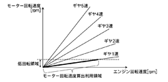
ここで、エンジン回転速度とモーター回転速度との関係について一例を図4のグラフに示す。このグラフに示す通り、特にギアが1速では誘導モーター11の回転速度(すなわちトランスミッション42の出力軸の回転速度)に対して、エンジン40の回転速度が高くなるため、回転速度検出切換部27においてエンジン40の回転速度センサーが検出した情報およびトランスミッション42のギア状態を示す情報を取得し、ギアが1速でかつエンジン40の回転速度が所定の回転速度よりも低い領域では、モーター回転速度算出部26により取得された回転速度信号(エンジン40の回転速度およびギア状態に基づいた回転速度信号)を速度制御部20に対して送出するように切り換え、それ以外の状態では、モーター回転速度算出部29により取得された回転速度信号(車速センサーに基づいた回転速度信号)を速度制御部20に対して送出するように切り換える。
Here, an example of the relationship between the engine rotation speed and the motor rotation speed is shown in the graph of FIG. As shown in this graph, the rotational speed of the engine 40 is higher than the rotational speed of the induction motor 11 (that is, the rotational speed of the output shaft of the transmission 42), especially when the gear is first gear. Information detected by the rotational speed sensor of the engine 40 and information indicating the gear state of the transmission 42 are acquired, and in a region where the gear is first speed and the rotational speed of the engine 40 is lower than a predetermined rotational speed, a motor rotational speed calculation unit 26 is switched so that the rotational speed signal (rotational speed signal based on the rotational speed of the engine 40 and the gear state) acquired by the engine 26 is sent to the speed controller 20, and in other states, the motor rotational speed calculator 29 The rotational speed signal (rotational speed signal based on the vehicle speed sensor) acquired by the Then switched to deliver to.
なお、減速比が1未満のギア段数以外は全て車速センサーよりもエンジン40の回転速度センサーの方が高い回転速度となるため、誘導モーター11の回転速度が低く車速センサーに基づいた回転速度信号の精度があまり高くない領域(図4中のグラフの点線よりも下の領域)では、1速だけでなく、減速比が1未満のギア段数を除いたすべてのギア段数においても、モーター回転速度算出部26により取得された回転速度信号(エンジン40の回転速度およびギア状態に基づいた回転速度信号)を速度制御部20に対して送出するように切り換えてもよい。
Since the rotational speed sensor of the engine 40 has a higher rotational speed than the vehicle speed sensor except for the number of gear stages with a reduction ratio of less than 1, the rotational speed signal of the rotational speed signal based on the vehicle speed sensor is low because the rotational speed of the induction motor 11 is low. In areas where the accuracy is not very high (areas below the dotted line in the graph in FIG. 4), the motor rotation speed is calculated not only for the 1st speed but also for all gear speeds except for the gear speed where the reduction ratio is less than 1. The rotation speed signal acquired by the unit 26 (the rotation speed signal based on the rotation speed of the engine 40 and the gear state) may be switched to be sent to the speed control unit 20.
速度制御部20は、自動車2側(リターダ10´外部)からの動作制御指令に基づいて、図2に示すような誘導モーターの特性に従い、回転速度検出切換部27から送出された回転速度信号に基づいて誘導モーター11のすべり量を調整し、誘導モーター11の適切な制御を行う。
Based on the operation control command from the automobile 2 side (outside the retarder 10 ′), the speed control unit 20 converts the rotation speed signal sent from the rotation speed detection switching unit 27 according to the characteristics of the induction motor as shown in FIG. Based on this, the slip amount of the induction motor 11 is adjusted, and the induction motor 11 is appropriately controlled.
このような態様とすることで、上記第1の実施の形態と同様の効果を得ることができ、さらに、処理が簡単である車速センサーが検出した情報に基づいて誘導モーター11を制御する方法を用いて誘導モーター11を制御しつつ、速度検出精度が低下する低速(低回転)領域では、エンジン40の回転速度センサーが検出した情報およびトランスミッション42のギア状態を示す情報に基づいて誘導モーター11を制御する方法を用いて、速度検出精度を向上させることができるので、効率的に誘導モーター11を制御することが可能となる。
By adopting such an aspect, it is possible to obtain the same effect as that of the first embodiment, and further, a method of controlling the induction motor 11 based on the information detected by the vehicle speed sensor that is easy to process. In the low speed (low rotation) region where the speed detection accuracy decreases while using the induction motor 11 to control the induction motor 11, the induction motor 11 is used based on information detected by the rotation speed sensor of the engine 40 and information indicating the gear state of the transmission 42. Since the speed detection accuracy can be improved by using the control method, the induction motor 11 can be controlled efficiently.
以上、本発明の好ましい実施の形態について説明したが、本発明は上記実施の形態に限定されるものではない。
The preferred embodiment of the present invention has been described above, but the present invention is not limited to the above embodiment.
例えば、上記第1および第2の実施の形態のいずれとも、エンジン40の回転速度センサーが検出した情報や車速センサーが検出した情報として自動車側1、2(リターダ10、10´外部)から受信する情報は、上記のようなデジタル信号に限らず、各センサーの出力信号そのもの(いわゆる回転パルス信号や車速パルス信号)であってもよく、その場合には、モーター回転速度算出部26、29において、受信したパルス信号を速度制御部20で誘導モーター11の回転速度を正しく認識可能な信号に変換して出力すればよい。なお、車速パルス信号について速度制御部20で誘導モーター11の回転速度を正しく認識可能な信号と同様の形態である場合には、変換は不要である。
For example, in both the first and second embodiments, information detected by the rotation speed sensor of the engine 40 and information detected by the vehicle speed sensor are received from the vehicle side 1 and 2 (outside of the retarders 10 and 10 '). The information is not limited to the digital signal as described above, but may be the output signal itself of each sensor (a so-called rotation pulse signal or vehicle speed pulse signal). In that case, in the motor rotation speed calculation units 26 and 29, The received pulse signal may be converted by the speed control unit 20 into a signal that can correctly recognize the rotation speed of the induction motor 11 and output. Note that if the vehicle speed pulse signal has the same form as a signal that allows the speed controller 20 to correctly recognize the rotational speed of the induction motor 11, no conversion is necessary.
また、上記以外にも、本発明の要旨を逸脱しない範囲において、各種の改良や変形を行なってもよいのは勿論である。
Of course, in addition to the above, various improvements and modifications may be made without departing from the scope of the present invention.