WO2013145976A1 - Structure de stator pour machine électrique tournante - Google Patents
Structure de stator pour machine électrique tournante Download PDFInfo
- Publication number
- WO2013145976A1 WO2013145976A1 PCT/JP2013/054467 JP2013054467W WO2013145976A1 WO 2013145976 A1 WO2013145976 A1 WO 2013145976A1 JP 2013054467 W JP2013054467 W JP 2013054467W WO 2013145976 A1 WO2013145976 A1 WO 2013145976A1
- Authority
- WO
- WIPO (PCT)
- Prior art keywords
- divided
- conductor
- stator core
- stator
- slots
- Prior art date
Links
Images


Classifications
-
- H—ELECTRICITY
- H02—GENERATION; CONVERSION OR DISTRIBUTION OF ELECTRIC POWER
- H02K—DYNAMO-ELECTRIC MACHINES
- H02K3/00—Details of windings
- H02K3/04—Windings characterised by the conductor shape, form or construction, e.g. with bar conductors
- H02K3/12—Windings characterised by the conductor shape, form or construction, e.g. with bar conductors arranged in slots
-
- H—ELECTRICITY
- H02—GENERATION; CONVERSION OR DISTRIBUTION OF ELECTRIC POWER
- H02K—DYNAMO-ELECTRIC MACHINES
- H02K3/00—Details of windings
- H02K3/04—Windings characterised by the conductor shape, form or construction, e.g. with bar conductors
- H02K3/28—Layout of windings or of connections between windings
-
- H—ELECTRICITY
- H02—GENERATION; CONVERSION OR DISTRIBUTION OF ELECTRIC POWER
- H02K—DYNAMO-ELECTRIC MACHINES
- H02K2213/00—Specific aspects, not otherwise provided for and not covered by codes H02K2201/00 - H02K2211/00
- H02K2213/03—Machines characterised by numerical values, ranges, mathematical expressions or similar information
Definitions
- the present invention relates to a stator structure of a rotating electrical machine operating as an electric motor or a generator, and more particularly to a stator structure of a rotating electrical machine housed in a slot of the stator and having a conductive member generating a rotating magnetic field.
- a stator is formed in an annular shape, and a rotor rotatably inserted in a central portion of the stator, and a coil wound around a slot of the stator generates a rotating magnetic field, and the rotor is A rotating electrical machine to rotate is known.
- the stator of the rotating electrical machine described above has, for example, a fan-shaped divided stator core obtained by dividing an annular stator into a plurality of parts as disclosed in WO 2011/055438, and assembles the divided stator core in an annular shape. Is what constitutes a stator. A tooth is formed in each of the divided stator cores, and a flat conductor, for example, is attached to the slot made of the tooth, and electrically connected by looping the flat conductor.
- each divided stator core is assembled from the outer peripheral side toward the inner peripheral side so as to form an annular ring, and an annular housing is provided on the outer peripheral portion, so that the divided stator core is assembled. It is configured to be held integrally.
- stator is configured by assembling a plurality of divided stator cores, the inner diameter of the stator varies. Therefore, it is necessary to set the gap with the rotor inserted inside the stator core in advance in consideration of the variation, and as a result, the size of the rotating electrical machine including the stator core is increased, and the performance of the rotating electrical machine It will inhibit the improvement.
- a general object of the present invention is to provide a stator structure of a rotating electrical machine capable of achieving improvement in performance by reducing loss while achieving downsizing by suppressing the height of a coil relative to a stator core. It is.
- the present invention is a rotating electrical machine comprising: a stator core having a plurality of slots and at least two or more of the slots integrally formed, and a coil provided in the slots,
- the coil is a U-shaped split conductor, and the split conductor is disposed across two slots in the stator core, and the first split conductor has a large pitch between the two slots;
- a second divided conductor having the same phase as the first divided conductor and having a smaller pitch with respect to the first divided conductor; Consists of In the crossover portion of the stator core, the second divided conductor is disposed within the pitch at which the first divided conductor is disposed.
- the first and second divided conductors formed in a U shape and disposed over the two slots in the stator core
- the first divided conductor is formed to have a large pitch between the two slots
- the second divided conductor is formed to have a smaller pitch with respect to the first divided conductor
- the first divided conductor and the second divided conductor formed in a U-shape can be reliably and easily assembled in the transition portion of the stator core without forming the stator core into a divided structure divided into at least slots. Therefore, it is possible to suppress the loss which is concerned when the stator core of the divided structure is adopted. As a result, it is possible to improve the output of the rotary electric machine by preventing the output reduction due to the loss. Further, since the first and second divided conductors have the same phase, it is possible to arrange the second divided conductors within the pitch at which the first divided conductors are arranged, with the second divided conductors being in close proximity to each other. Become.
- the height (volume) of the first and second divided conductors in the axial direction of the stator core can be suppressed, and the thickness along the axial direction of the rotating electrical machine including the stator core Can be miniaturized.
- the stator which comprises the rotary electric machine which concerns on embodiment of this invention WHEREIN It is an external appearance perspective view which shows the state from which the 1st and 2nd divided conductor which comprises a conductor was taken out upwards. It is an external appearance perspective view of the 1st and 2nd division conductor shown in FIG. It is an enlarged perspective view which shows the state in which the 1st and 2nd division
- FIG. 6 is a cross-sectional view showing a state in which first and second divided conductors are attached to slots of the stator core of FIG. 3. It is the perspective view which looked at the 1st and 2nd division
- the rotary electric machine 10 is, for example, a three-phase AC brushless motor, and has an annular stator 12 as shown in FIG. 1.
- a rotor (not shown) is rotatably inserted into the stator 12, and the rotary electric machine 10 receives power supplied from a power source (not shown) via U-phase terminals, V-phase terminals and W-phase terminals (not shown).
- the rotor is rotationally driven on the basis of this.
- the stator 12 includes an annular stator core 14, teeth 16 projecting from the stator core 14 to the inner diameter side, and a plurality of conductors mounted in slots 34 provided on the outer circumferential side with respect to the teeth 16. (Coil) 18 and.
- the stator core 14 has a plurality of steel plates laminated in the axial direction (arrows A1 and A2 directions), and integrally integrated in the axial direction (arrows A1 and A2 directions) by a plurality of caulking pins 20 equally spaced in the circumferential direction. It is formed by caulking.
- the stator core 14 is not limited to the case where it is formed in a ring-shaped integral shape, and, for example, is configured by assembling a plurality of divided bodies in which at least two or more adjacent slots 34 are integrally provided. It may be a stator core of divided structure.
- the conductor 18 is formed, for example, in a substantially U shape in which a flat rectangular plate having a rectangular cross section is bent, and the pair of straight portions 22a, 22b, 24a, 24b and
- the first and second divided conductors 30, 32 have tops 26, 28 respectively connecting one ends of the straight portions 22a, 22b, 24a, 24b.
- the first and second divided conductors 30, 32 may be any of the U-phase terminal, the V-phase terminal, and the W-phase terminal so that they have the same phase (for example, U-phase, V-phase, W-phase). Each connected.
- one straight portion 22a, 24a and the other straight portion 22b, 24b are formed substantially parallel to each other at a predetermined distance from each other, with respect to the slot 34 of the stator core 14.
- Each is inserted.
- a plurality of slots 34 are provided at equal intervals along the circumferential direction of the stator core 14, and are formed to penetrate along the axial direction (directions of arrows A1 and A2) of the stator core 14.
- the straight portions 22a, 22b, 24a, 24b are set to have a length along the axial direction (arrows A1, A2 direction) longer than a thickness dimension along the axial direction (directions of arrows A1, A2) of the stator core 14. It is done. Therefore, when the straight portions 22a, 22b, 24a, 24b are respectively inserted into the two slots 34 from the one end face 14a side of the stator core 14, the other end is only a predetermined length with respect to the other end face 14b of the stator core 14. Stand out.
- the separation distance L1 between the pair of straight portions 22a and 22b in the first divided conductor 30 is the separation distance L2 between the pair of straight portions 24a and 24b in the second divided conductor 32, as shown in FIG. It is set large for. That is, the first divided conductor 30 has a large separation distance L1 between the straight portions 22a and 22b, and the second divided conductor 32 has a separation distance L2 between the straight portions 24a and 24b to the first divided conductor 30. And formed to be small (L1> L2).
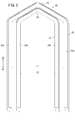
- the apexes 26, 28 are, for example, inclined at a predetermined angle with respect to one end of the straight portions 22a, 22b, 24a, 24b and extend in a direction away from the straight portions 22a, 22b, 24a, 24b. There is.
- the tops 26, 28 extend in a direction in which the portion connected to one of the straight portions 22a, 24a and the portion connected to the other straight portions 22b, 24b are inclined at a predetermined angle and approach each other.
- the ridges are formed so that the central portions of the tops 26, 28 are at the highest.
- the tops 26 and 28 are not limited to the above-described mountain shape, and may have, for example, a curved arc shape.
- the first and second divided conductors 30, 32 align the tops 26, 28 with each other on a straight line, and the second divided conductor 32 is the second
- the stator core 14 is mounted so as to be inside the one-divided conductor 30, that is, on the stator core 14 side (in the direction of the arrow A1). Further, since the first divided conductor 30 has a large pitch (distance L1) between the pair of straight portions 22a and 22b, the circumferential direction outer side adjacent to the slot 34 into which the straight portions 24a and 24b of the second divided conductor 32 are inserted. Are respectively inserted into different slots 34a.
- the second divided conductors 32 are arranged within the pitch of the slots 34 a in which the first divided conductors 30 are arranged.
- the straight portions 22 a and 22 b of the first divided conductor 30 and the straight portions 24 a and 24 b of the second divided conductor 32 are inserted into the slots 34 a and 34 different in the circumferential direction in the stator core 14. Be done.
- first and second divided conductors 30, 32 have the straight portions 22a, 22b, 24a, 24b inserted in the slots 34a, 34 of the stator core 14, respectively.
- First and second connection portions 36 and 38 are formed by twisting and bending the other end portions protruding from the slots 34 a and 34 along the circumferential direction of the stator core 14.
- the first connection portion 36 is bent inward in the circumferential direction with respect to the pair of terminal portions 36a which are respectively bent outward in the circumferential direction with respect to the pair of straight portions 22a and 22b, and with respect to the straight portions 22a and 22b. It comprises a set of bent terminal portions 36b.
- the second connection portion 38 is bent inward in the circumferential direction with respect to the pair of terminal portions 38a and the straight portions 24a and 24b respectively bent outward in the circumferential direction with respect to the pair of straight portions 24a and 24b. It comprises a set of bent terminal portions 38b.
- connection portions 36, 38 are bent at the portions where the straight portions 22a, 22b, 24a, 24b protrude outward from the slots 34a, 34, respectively.
- the connection portions 36, 38 are locked to the other end surface 14b of the stator core 14 (see FIG. 4).
- the linear portions 22a, 22b, 24a, 24b of the first and second divided conductors 30, 32 are prevented from moving in the axial direction (directions of arrows A1, A2) in the slots 34, 34a.
- the apexes 26, 28 are disposed on the side of one end 14a of the stator core 14 (in the direction of arrow A2), and the straight portions 22a, 22b, 24a, 24b are inserted into the slots 34, 34a. It is fixed firmly in the state.
- the lead wires 40a are respectively connected to the terminal portions 36a and 36b constituting the first connection portion 36, for example, by welding etc., and another first set in the adjacent slots 34a. It is electrically connected to the first connection portion 36 of the divided conductor 30.
- the conductor 40b is connected to the terminal portions 38a and 38b constituting the second connection portion 38, and the second connection portion 38 of another second divided conductor 32 mounted in the adjacent slot 34 is electrically connected.
- the plurality of first and second divided conductors 30, 32 mounted on the stator core 14 are electrically connected to each other through the conductors 40a, 40b to form a circuit.
- first and second connection portions 36, 38 function as connection terminals for electrically connecting the adjacent first and second divided conductors 30, 32, and at the same time, the first and second connection portions 36, 38 for the stator core 14 It also functions as a stopper for preventing displacement of the second divided conductors 30, 32 in the axial direction (directions of arrows A1, A2).
- the straight portions 22a and 22b of the first divided conductor 30 are respectively inserted into the same slots 34a as the straight portions 22a and 22b of another first divided conductor 30 adjacent in the same phase. Be done.
- the straight portions 24 a and 24 b of the second divided conductor 32 are inserted into the same slot 34 as another second divided conductor 32 of a phase different from that of the second divided conductor 32.
- another second divided conductor 32 disposed in the same slot 34 as the second divided conductor 32 is the furthest from the U-phase terminal, the V-phase terminal, and the W-phase terminal serving as input terminals in each phase, and the middle point side It is preferable to arrange what is connected to.
- the first and second divided conductors 30, 32 formed in a substantially U shape are provided as the conductor 18, and the slots 34 of the stator core 14 formed integrally in an annular shape are provided. It is fixed to the stator core 14 by inserting in the axial direction (directions of arrows A1 and A2) and bending the other end. Therefore, in the rotary electric machine 10, the first and second divided conductors 30, 32 can be reliably and easily assembled without using the stator core 14 in a divided structure, and there is a concern when adopting a divided stator core. Can be suppressed, so that it is possible to prevent the power reduction due to the loss. As a result, the output of the rotating electrical machine 10 can be improved.
- stator core 14 is divided into at least slots 34
- the integral shape suppresses the variation in the inner peripheral diameter of stator core 14, so that the variation is taken into consideration. It is possible to set a small gap (gap) between the inner peripheral surface of the stator core 14 and the rotor. Therefore, as shown in FIG. 7, the rotating electric machine according to the prior art adopting the stator core of the split structure (the solid line in FIG. 7) when the same current is supplied to rotating electric machine 10 It can be increased as compared with the broken line in FIG. As a result, it is possible to improve the performance of the rotary electric machine having the stator core of the conventional divided structure.
- stator core 14 is divided into at least slots 34
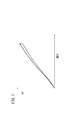
- residual stress generated when assembling stator core 14 can be reduced. Therefore, as shown in FIG. 8, the loss (solid line in FIG. 8) in the case of rotating the rotor of the rotary electric machine 10 at the same number of rotations is shown in FIG. It can be reduced compared to the loss (broken line in FIG. 8).
- the permeability can be improved and the output can be improved with respect to the rotary electric machine having the stator core of the conventional divided structure.
- the second divided conductor 32 is disposed inside the first divided conductor 30, and It is possible to arrange the tops 26, 28 of the two in close proximity to each other.
- the height H (crossing height) of the first and second divided conductors 30, 32 with respect to one end face 14a of the stator core 14 can be suppressed, and the axial direction of the rotary electric machine 10 including the stator core 14 (arrow A1, The thickness along the direction A2) can be miniaturized. At the same time, torque can be output smoothly from the rotor.
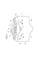
- first and second divided conductors 30, 32 are provided in the circumferential direction of the stator core 14, and the first divided conductors 30 adjacent in the circumferential direction are connected to each other through the first connection portions 36.
- the second divided conductors 32 are connected to each other through the second connection portions 38 of each other. Therefore, as shown in FIG. 6, the conductor 18 composed of the first and second divided conductors 30, 32 is alternately arranged in the wave winding and the lap winding with respect to the stator core 14, and in the slots. It is possible to provide two-layer winding in which the first and second divided conductors 30, 32 of different phases are disposed. As a result, the pitch of the first and second divided conductors 30 and 32 can be shortened, and the height H (crossing height) along the axial direction of the stator core 14 can be suppressed.
- the linear portions 22a, 22b of the first divided conductors 30, which are the same phase adjacent to each other are identical slots.
- U-phase terminals, V-phase terminals and W-phases serving as input terminals in each phase
- stator core 14 described above is integrally formed by caulking the laminated steel plates by a plurality of caulking pins 20, compared with the stator core of the divided structure according to the prior art, the caulking points The number of tightening pins 20 can be set small. As a result, it is possible to reduce the number of parts and the number of assembling steps in the rotary electric machine 10, and to reduce the loss.
- stator structure of the rotary electric machine according to the present invention is, of course, not limited to the above embodiment, and various configurations can be adopted without departing from the scope of the present invention.
Landscapes
- Engineering & Computer Science (AREA)
- Power Engineering (AREA)
- Windings For Motors And Generators (AREA)
- Iron Core Of Rotating Electric Machines (AREA)
Abstract
Priority Applications (4)
| Application Number | Priority Date | Filing Date | Title |
|---|---|---|---|
| CN201380016573.7A CN104205575B (zh) | 2012-03-29 | 2013-02-22 | 旋转电机的定子结构 |
| DE112013001733.4T DE112013001733T5 (de) | 2012-03-29 | 2013-02-22 | Statorkonstruktion für rotierende elektrische Maschine |
| JP2014507530A JP5918353B2 (ja) | 2012-03-29 | 2013-02-22 | 回転電機のステータ構造 |
| US14/388,728 US9531227B2 (en) | 2012-03-29 | 2013-02-22 | Stator structure for rotary electric machine |
Applications Claiming Priority (2)
| Application Number | Priority Date | Filing Date | Title |
|---|---|---|---|
| JP2012076311 | 2012-03-29 | ||
| JP2012-076311 | 2012-03-29 |
Publications (1)
| Publication Number | Publication Date |
|---|---|
| WO2013145976A1 true WO2013145976A1 (fr) | 2013-10-03 |
Family
ID=49259256
Family Applications (1)
| Application Number | Title | Priority Date | Filing Date |
|---|---|---|---|
| PCT/JP2013/054467 WO2013145976A1 (fr) | 2012-03-29 | 2013-02-22 | Structure de stator pour machine électrique tournante |
Country Status (5)
| Country | Link |
|---|---|
| US (1) | US9531227B2 (fr) |
| JP (1) | JP5918353B2 (fr) |
| CN (1) | CN104205575B (fr) |
| DE (1) | DE112013001733T5 (fr) |
| WO (1) | WO2013145976A1 (fr) |
Cited By (3)
| Publication number | Priority date | Publication date | Assignee | Title |
|---|---|---|---|---|
| WO2017217271A1 (fr) * | 2016-06-16 | 2017-12-21 | 三菱電機株式会社 | Stator pour machine électrique rotative |
| WO2020195129A1 (fr) * | 2019-03-28 | 2020-10-01 | 株式会社デンソー | Machine électrique tournante et son stator |
| WO2022208929A1 (fr) * | 2021-03-29 | 2022-10-06 | 日立Astemo株式会社 | Stator pour machine électrique tournante et machine électrique tournante |
Families Citing this family (24)
| Publication number | Priority date | Publication date | Assignee | Title |
|---|---|---|---|---|
| DE112013001733T5 (de) * | 2012-03-29 | 2015-02-26 | Honda Motor Co., Ltd. | Statorkonstruktion für rotierende elektrische Maschine |
| CN105762947B (zh) * | 2016-04-29 | 2017-06-27 | 上海浦赛动力科技有限公司 | 电枢、用于电枢的端部模块和用于装配电枢的方法 |
| DE102017208706A1 (de) * | 2016-09-27 | 2018-03-29 | Robert Bosch Gmbh | Stator für eine elektrische Maschine |
| CN109586452B (zh) * | 2017-09-29 | 2021-08-10 | 比亚迪股份有限公司 | 定子组件和具有其的电机和车辆 |
| CN109586466B (zh) * | 2017-09-29 | 2021-09-21 | 比亚迪股份有限公司 | 定子组件和具有其的电机和车辆 |
| CN109586455B (zh) * | 2017-09-29 | 2021-11-12 | 比亚迪股份有限公司 | 定子组件和具有其的电机和车辆 |
| CN109586453B (zh) * | 2017-09-29 | 2021-08-10 | 比亚迪股份有限公司 | 定子组件和具有其的电机和车辆 |
| CN109586430B (zh) * | 2017-09-29 | 2021-02-23 | 比亚迪股份有限公司 | 定子组件和电机 |
| CN109586464B (zh) * | 2017-09-29 | 2021-11-12 | 比亚迪股份有限公司 | 定子组件、电机和车辆 |
| CN109586461B (zh) * | 2017-09-29 | 2021-08-10 | 比亚迪股份有限公司 | 定子组件和具有其的电机和车辆 |
| CN109586463B (zh) * | 2017-09-29 | 2021-08-10 | 比亚迪股份有限公司 | 定子组件和具有其的电机和车辆 |
| CN109586454B (zh) * | 2017-09-29 | 2021-07-20 | 比亚迪股份有限公司 | 定子组件和具有其的电机和车辆 |
| DE102017128832A1 (de) * | 2017-12-05 | 2019-06-06 | Ebm-Papst Mulfingen Gmbh & Co. Kg | Multi-Zahnspulenwicklung für eine 3-strängige Drehfeldmaschine |
| JP6508318B1 (ja) * | 2017-12-25 | 2019-05-08 | 株式会社明電舎 | 回転機の固定子 |
| JP6680815B2 (ja) * | 2018-02-07 | 2020-04-15 | 本田技研工業株式会社 | 電気導体の曲げ方法及び装置 |
| US11018545B2 (en) * | 2018-08-03 | 2021-05-25 | Ford Global Technologies, Llc | Electric machine winding assembly |
| CN110417152A (zh) * | 2018-10-24 | 2019-11-05 | 天津市松正电动汽车技术股份有限公司 | 一种电机定子及电机 |
| US11095197B2 (en) * | 2018-10-31 | 2021-08-17 | GM Global Technology Operations LLC | Modular stator |
| US11539255B2 (en) | 2020-03-24 | 2022-12-27 | Ford Global Technologies, Llc | Hairpin winding electric machine |
| US11309761B2 (en) | 2020-03-24 | 2022-04-19 | Ford Global Technologies, Llc | Hairpin winding electric machine |
| JP7042295B2 (ja) * | 2020-03-30 | 2022-03-25 | 本田技研工業株式会社 | 波巻コイルの製造方法及び回転電機のステータ |
| US11368066B2 (en) * | 2020-04-03 | 2022-06-21 | Ford Global Technologies, Llc | Hairpin winding electric machine |
| JP2021175215A (ja) | 2020-04-20 | 2021-11-01 | 株式会社デンソー | 回転電機 |
| CN113036953B (zh) * | 2021-03-04 | 2022-04-05 | 中国第一汽车股份有限公司 | 一种插针绕组式定子及电机 |
Citations (8)
| Publication number | Priority date | Publication date | Assignee | Title |
|---|---|---|---|---|
| JPS62188944U (fr) * | 1986-05-19 | 1987-12-01 | ||
| JPH05161292A (ja) * | 1991-11-29 | 1993-06-25 | Toshiba Corp | 三相電機子巻線 |
| JP2001069707A (ja) * | 1999-06-25 | 2001-03-16 | Denso Corp | 回転電機およびその製造方法 |
| US7005772B1 (en) * | 2005-04-06 | 2006-02-28 | Visteon Global Technologies, Inc. | Stator winding having two slots per phase per pole |
| JP2006094694A (ja) * | 2004-08-27 | 2006-04-06 | Denso Corp | セグメント導体型電機子 |
| JP2010239798A (ja) * | 2009-03-31 | 2010-10-21 | Aisin Aw Co Ltd | 回転電機用電機子 |
| JP2011120356A (ja) * | 2009-12-02 | 2011-06-16 | Toyota Motor Corp | ステータおよびステータ製造方法 |
| JP2011182524A (ja) * | 2010-02-26 | 2011-09-15 | Aisin Aw Co Ltd | 回転電機用電機子 |
Family Cites Families (17)
| Publication number | Priority date | Publication date | Assignee | Title |
|---|---|---|---|---|
| DE3008212C2 (de) * | 1980-03-04 | 1985-06-27 | Robert Bosch Gmbh, 7000 Stuttgart | Verfahren zur Herstellung von Statorwicklungen für Dreiphasen-Drehstromgeneratoren |
| JP3384337B2 (ja) * | 1998-09-07 | 2003-03-10 | 株式会社デンソー | 車両用交流発電機の固定子 |
| JP3823608B2 (ja) * | 1999-06-01 | 2006-09-20 | 株式会社デンソー | 車両用交流発電機 |
| JP3621635B2 (ja) * | 2000-08-10 | 2005-02-16 | 三菱電機株式会社 | 回転電機 |
| JP3734160B2 (ja) * | 2001-12-13 | 2006-01-11 | 株式会社デンソー | 回転電機のステータの製造方法 |
| US6979926B2 (en) * | 2002-06-12 | 2005-12-27 | Denso Corporation | Sequentially joined-segment coil for rotary electrical machine |
| JP3988617B2 (ja) | 2002-09-18 | 2007-10-10 | 株式会社デンソー | セグメント導体接合型電機子及びこの電機子を備えた交流機 |
| JP2004229460A (ja) * | 2003-01-27 | 2004-08-12 | Mitsubishi Electric Corp | 回転電機の固定子 |
| JP4449653B2 (ja) * | 2004-08-25 | 2010-04-14 | 株式会社デンソー | セグメント導体型電機子 |
| US7348705B2 (en) | 2005-07-21 | 2008-03-25 | Remy Technologies, L.L.C. | Multi-phase fractional slot windings for electric machines having segmented bar-shaped windings |
| JP2007215305A (ja) * | 2006-02-08 | 2007-08-23 | Denso Corp | モータおよびその制御装置 |
| JP4946421B2 (ja) * | 2006-12-20 | 2012-06-06 | 株式会社デンソー | 回転電機の巻線接合方法 |
| JP5429132B2 (ja) * | 2009-10-23 | 2014-02-26 | 株式会社デンソー | 回転電機の固定子の製造方法および回転電機の固定子 |
| US20120223611A1 (en) | 2009-11-05 | 2012-09-06 | Toyota Jidosha Kabushiki Kaisha | Stator and method for manufacturing stator |
| JP5663191B2 (ja) * | 2010-04-27 | 2015-02-04 | 本田技研工業株式会社 | モータの固定子 |
| US8916999B2 (en) * | 2011-01-01 | 2014-12-23 | Asmo Co., Ltd. | Motors containing segment conductor coils |
| DE112013001733T5 (de) * | 2012-03-29 | 2015-02-26 | Honda Motor Co., Ltd. | Statorkonstruktion für rotierende elektrische Maschine |
-
2013
- 2013-02-22 DE DE112013001733.4T patent/DE112013001733T5/de not_active Withdrawn
- 2013-02-22 CN CN201380016573.7A patent/CN104205575B/zh active Active
- 2013-02-22 WO PCT/JP2013/054467 patent/WO2013145976A1/fr active Application Filing
- 2013-02-22 US US14/388,728 patent/US9531227B2/en active Active
- 2013-02-22 JP JP2014507530A patent/JP5918353B2/ja active Active
Patent Citations (8)
| Publication number | Priority date | Publication date | Assignee | Title |
|---|---|---|---|---|
| JPS62188944U (fr) * | 1986-05-19 | 1987-12-01 | ||
| JPH05161292A (ja) * | 1991-11-29 | 1993-06-25 | Toshiba Corp | 三相電機子巻線 |
| JP2001069707A (ja) * | 1999-06-25 | 2001-03-16 | Denso Corp | 回転電機およびその製造方法 |
| JP2006094694A (ja) * | 2004-08-27 | 2006-04-06 | Denso Corp | セグメント導体型電機子 |
| US7005772B1 (en) * | 2005-04-06 | 2006-02-28 | Visteon Global Technologies, Inc. | Stator winding having two slots per phase per pole |
| JP2010239798A (ja) * | 2009-03-31 | 2010-10-21 | Aisin Aw Co Ltd | 回転電機用電機子 |
| JP2011120356A (ja) * | 2009-12-02 | 2011-06-16 | Toyota Motor Corp | ステータおよびステータ製造方法 |
| JP2011182524A (ja) * | 2010-02-26 | 2011-09-15 | Aisin Aw Co Ltd | 回転電機用電機子 |
Cited By (6)
| Publication number | Priority date | Publication date | Assignee | Title |
|---|---|---|---|---|
| WO2017217271A1 (fr) * | 2016-06-16 | 2017-12-21 | 三菱電機株式会社 | Stator pour machine électrique rotative |
| JPWO2017217271A1 (ja) * | 2016-06-16 | 2018-08-30 | 三菱電機株式会社 | 回転電機の固定子 |
| WO2020195129A1 (fr) * | 2019-03-28 | 2020-10-01 | 株式会社デンソー | Machine électrique tournante et son stator |
| JP2020167790A (ja) * | 2019-03-28 | 2020-10-08 | 株式会社デンソー | 回転電機、およびその固定子 |
| JP7052767B2 (ja) | 2019-03-28 | 2022-04-12 | 株式会社デンソー | 回転電機、およびその固定子 |
| WO2022208929A1 (fr) * | 2021-03-29 | 2022-10-06 | 日立Astemo株式会社 | Stator pour machine électrique tournante et machine électrique tournante |
Also Published As
| Publication number | Publication date |
|---|---|
| CN104205575B (zh) | 2017-03-01 |
| JP5918353B2 (ja) | 2016-05-18 |
| CN104205575A (zh) | 2014-12-10 |
| US9531227B2 (en) | 2016-12-27 |
| JPWO2013145976A1 (ja) | 2015-12-10 |
| US20150091408A1 (en) | 2015-04-02 |
| DE112013001733T5 (de) | 2015-02-26 |
Similar Documents
| Publication | Publication Date | Title |
|---|---|---|
| WO2013145976A1 (fr) | Structure de stator pour machine électrique tournante | |
| EP3007319B1 (fr) | Machine électrique rotative, et procédé de fabrication de cette dernière | |
| JP6336193B2 (ja) | 永久磁石式三相二重化モータおよび電動パワーステアリング装置 | |
| JP5986774B2 (ja) | 回転電機 | |
| US8610328B2 (en) | Rotary electric machine | |
| US10236738B2 (en) | Rotary electric machine | |
| JP6120987B2 (ja) | 電気機械の電機子 | |
| JP6046987B2 (ja) | ステータ、ブラシレスモータ、ステータの製造方法 | |
| US20150162793A1 (en) | Stator | |
| US20150349597A1 (en) | Rotary electric machine and method for manufacturing an armature that is used in the rotary electric machine | |
| CN108370184B (zh) | 旋转电机 | |
| CN108736614B (zh) | 旋转电机的定子 | |
| JP5626758B2 (ja) | ステータ | |
| JP6337132B2 (ja) | 回転電機の固定子、及びこれを備えた回転電機 | |
| JP5995883B2 (ja) | 回転電機の固定子 | |
| JP2009118636A (ja) | 回転電機および回転電機の製造方法 | |
| US20190372408A1 (en) | Rotating electric machine | |
| US20150372551A1 (en) | Structure of stator | |
| WO2015104734A1 (fr) | Procédé de fabrication de stator divisé pour machine électrique qui effectue une conversion entre l'énergie électrique et l'énergie mécanique, stator divisé, et machine électrique utilisant ledit stator divisé | |
| JP5909790B2 (ja) | 回転電機、回転電機用ステータおよび車両 | |
| JP2015136195A (ja) | 回転電機の固定子 | |
| JP5607852B1 (ja) | 電気エネルギーと機械エネルギーとを変換する電気機械装置 | |
| CN109802499B (zh) | 旋转电机的定子以及旋转电机 | |
| JP5909789B2 (ja) | 回転電機、回転電機用ステータおよび車両 | |
| JP2014103707A (ja) | 回転電機のステータ |
Legal Events
| Date | Code | Title | Description |
|---|---|---|---|
| 121 | Ep: the epo has been informed by wipo that ep was designated in this application |
Ref document number: 13768320 Country of ref document: EP Kind code of ref document: A1 |
|
| ENP | Entry into the national phase |
Ref document number: 2014507530 Country of ref document: JP Kind code of ref document: A |
|
| WWE | Wipo information: entry into national phase |
Ref document number: 14388728 Country of ref document: US |
|
| WWE | Wipo information: entry into national phase |
Ref document number: 1120130017334 Country of ref document: DE Ref document number: 112013001733 Country of ref document: DE |
|
| 122 | Ep: pct application non-entry in european phase |
Ref document number: 13768320 Country of ref document: EP Kind code of ref document: A1 |