WO2013145367A1 - 貨物車両のデッキ構造 - Google Patents
貨物車両のデッキ構造 Download PDFInfo
- Publication number
- WO2013145367A1 WO2013145367A1 PCT/JP2012/072569 JP2012072569W WO2013145367A1 WO 2013145367 A1 WO2013145367 A1 WO 2013145367A1 JP 2012072569 W JP2012072569 W JP 2012072569W WO 2013145367 A1 WO2013145367 A1 WO 2013145367A1
- Authority
- WO
- WIPO (PCT)
- Prior art keywords
- reinforcing plate
- coupled
- sill
- wheel house
- stress relaxation
- Prior art date
- Legal status (The legal status is an assumption and is not a legal conclusion. Google has not performed a legal analysis and makes no representation as to the accuracy of the status listed.)
- Ceased
Links
Images




Classifications
-
- B—PERFORMING OPERATIONS; TRANSPORTING
- B62—LAND VEHICLES FOR TRAVELLING OTHERWISE THAN ON RAILS
- B62D—MOTOR VEHICLES; TRAILERS
- B62D33/00—Superstructures for load-carrying vehicles
- B62D33/077—Superstructures for load-carrying vehicles characterised by the connection of the superstructure to the vehicle frame
Definitions
- This invention relates to the structure of a cargo vehicle deck.
- a freight vehicle pickup truck, etc. having a cabin (passenger compartment) at the front of the vehicle and a deck (loading platform) behind it, a plurality of cross members straddling between the left and right side members that support the engine, suspension, etc. And a deck structure in which a cabin and a deck floor panel are coupled to each other.
- reinforcing members called sill cloths are connected to the left and right ends of the cross members in the front row of the plurality of cross members, and the deck floor panel and the end of the wheel house are connected to the sill crosses.
- a reinforcing plate called a shear patch may be joined by spot welding or the like across the sill cross end and the wheel house.
- a freight vehicle deck structure includes a cross member extending in the vehicle width direction coupled between left and right side members, a sill cross coupled to an end of the cross member, A deck floor panel coupled to the upper surface, a wheel house coupled to the floor panel and having a rear wheel disposed therein, and a reinforcing plate coupled across the end of the sill cloth and the wheel house are provided.
- the reinforcing plate has a recess formed by cutting from the front side of the vehicle to the rear side, and a stress relaxation end portion bent inward in the vehicle width direction at the lower side of the recess, and the sill cloth at the stress relaxation end portion. Is bound to.
- the reinforcing plate mainly absorbs the displacement in the vertical direction with respect to the sill cloth of the wheel house, and the stress concentration on the connecting portion (second connecting portion) of the reinforcing plate with respect to the wheel house is relieved, and the separation or Generation of cracks is suppressed.
- the stress relaxation end portion formed by bending on the reinforcing plate is coupled to the sill cloth, so that the load acting to peel in the vehicle width direction intersecting the second coupling portion (the load in the peeling direction of the second coupling portion). ) Can be received by the joint portion (third joint portion) of the stress relaxation end portion with respect to the sill cloth, and in this respect also, the second joint portion can be prevented from peeling or cracking.
- the distance between the second coupling portion and the third coupling portion can be made larger than before, the load input to each coupling portion can be reduced. Can be suppressed.
- the reinforcing plate is effectively subjected to a load at the second coupling portion and the third coupling portion, and the reinforcing plate is prevented from peeling or cracking of the first coupling portion. It is possible to obtain the same effect as that of increasing the size or expanding the location of the coupling portion.
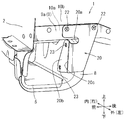
- FIG. 4 is a sectional view taken along the line IV-IV in FIG. 3 and is a longitudinal sectional view of a reinforcing plate attachment portion.
- FIG. 5 is a cross-sectional view taken along the line VV in FIG. 3 and is a cross-sectional view of a reinforcing plate attachment portion.
- FIG. 1 shows an open deck 1 (loading platform) of a freight vehicle, also called a pickup truck.
- the deck 1 has a bottom shallow box shape with an open top, including a deck floor, a front wall 2, left and right side walls 3, and a rear wall 4 that can be opened and closed.
- the front wall 2, the left side wall 3 and the rear wall 4 are visible, and the deck floor and the right side wall 3 are not visible.
- a wheel house 10 that forms a space for arranging a rear wheel (not shown) is provided on the inner side of the left side wall 3.
- the deck 1 is supported on the left and right side members 11.
- a plurality of cross members are coupled to the left and right side members 11 so as to span the members.
- a floor panel 9 (see FIG. 4) constituting a deck floor is coupled to the plurality of cross members.
- the foremost cross member 5 has a so-called sill cross 8 as a reinforcing member coupled to each of the left and right ends.
- the floor panel 9 is coupled to the upper surface of the sill cloth 8.
- the wheel house 10 is composed of a panel member and has at least a vertical wall 10b facing the inner side of the rear wheel as shown in FIG.
- a horizontal edge portion 10c of the wheel house 10 is coupled to the upper surface of the floor panel 9 so as to overlap each other.
- the overlapped floor panel 9 and the horizontal edge 10c of the wheel house 10 are joined to the upper surface of the sill cloth 8 at a plurality of locations by spot welding.
- the spot-welded part is referred to as a first spot 21.
- the spot welding spot portions are indicated by crosses.
- the end of the floor panel 9 on the outer side in the vehicle width direction is bent upward to form a vertical edge 9a.
- the vertical edge 9a serves as a connecting portion for connecting to the wheel house 10.
- the vertical edge portion 9 a of the floor panel 9 is overlapped with the surface on the outer side (wheel side) of the vertical wall of the wheel house 10.
- the structure in which the sill cross 8, the floor panel 9, and the wheel house 10 are combined at the left and right ends of the cross member 5 as described above is reinforced by a reinforcing plate 20 called a shear patch formed of a metal plate.
- the reinforcing plate 20 is disposed on both the wheel house 10 and the sill cloth 8 so as to extend vertically, and is coupled to the vertical wall 10 b of the wheel house 10 and the end face of the sill cloth 8.
- the reinforcing plate 20 is coupled to the wheel house 10 so as to sandwich the vertical edge portion of the floor panel 9 therebetween.
- the upper portion of the reinforcing plate 20 is coupled to the vertical edge portion 9a of the floor panel 9 and the vertical wall 10b of the wheel house 10 by spot welding.
- the spot welded portion is referred to as a second spot 22.
- the reinforcing plate 20 is provided with a recess 20a that opens at the front edge. As shown in FIGS. 2 and 3, the recess 20 a is cut in a U shape from the front edge of the reinforcing plate 20 to the rear. Therefore, the recess 20a has a semicircular arc-shaped edge at the rear part, so that stress concentration hardly occurs.
- the reinforcing plate 20 is provided with a stress relaxation end portion 20b on the lower side of the concave portion 20a.
- the stress relaxation end portion 20b is an end portion formed by bending the reinforcing plate 20 inward in the vehicle width direction.
- the stress relaxation end portion 20b is joined to the front surface (inner side surface) of the vertical wall 10b of the sill cloth 8 at two locations, upper and lower, by spot welding.
- the spot welded portion is referred to as a third spot portion 23.
- the reinforcing plate 20 is formed with a bead portion 20c having a semicircular cross section and curved so as to swell forward along the fold of the stress relaxation end portion 20b.
- the bead portion 20c By this bead portion 20c, the displacement in the front-rear direction of the stress relaxation end portion 20b is mainly absorbed, and the stress concentration on the second hit point portion 22 and the third hit point portion 23 is reduced.
- the reinforcing plate 20 is coupled across the wheel house 10 and the sill cloth 8.
- the reinforcement board 20 can receive the load of the direction which the wheel house 10 and the sill cloth 8 peel, and peeling of the 1st hit point part 21 which is a coupling
- the reinforcing plate 20 is provided with a recess 20a.
- the reinforcing plate is coupled to the wheel house 10 at the upper portion (second hitting point portion 22) from the recess 20a and is connected to the sill cloth 8 at the lower portion (third hitting point portion 23).
- the relative displacement in the vertical direction and the vehicle width direction of the structure on the upper side (wheel house side) and the lower side (sill cross side) is easily allowed.
- Load F is easily absorbed. Therefore, the stress concentration with respect to the second hit point portion 22 and the third hit point portion 23 is alleviated, and the occurrence of peeling or cracking is suppressed. Therefore, the durability of the first hit point 21 can be further enhanced in this respect.
- the reinforcing plate 20 has a stress relaxation end portion 20b formed by being bent in the vehicle width direction below the concave portion 20a.
- the reinforcing plate 20 is coupled to the sill cloth 8 at the stress relaxation end portion 20b.
- a load in the vehicle width direction that causes the second striking portion 22 to peel off can be received by the third striking portion 23 that is a joint portion of the stress relaxation end portion to the sill cloth. Generation of cracks can be suppressed.
- the stress relaxation end portion 20b allows the distance between the second hit point portion 22 and the third hit point portion 23 (distance between the hit points) to be a flat plate shape having no conventional shear patch (a bent portion forming the stress relaxation end portion).
- the reinforcing plate can be set larger than that of the reinforcing plate. Therefore, the stress concentration on the second hit point portion 22 and the third hit point portion 23 can be relaxed.
- the reinforcing plate includes the recess 20a and the stress relaxation end portion 20b, the second hit point portion 22 and the third hit point portion 23 can receive a load effectively. Therefore, regarding the occurrence of peeling or cracking of the first spot portion 21, it is possible to obtain the same effect as when the reinforcing plate is enlarged or the number of spot welding spots is increased.
- a bead portion 20c that is curved in a semicircular cross section is formed in the reinforcing plate 20 along the fold of the stress relaxation end portion 20b.
- the bead part absorbs the displacement of the stress relaxation end part in the front-rear direction and the vehicle width direction, and the load on the second hit point part 22 and the third hit point part 23 can be reduced.
- the load F input from the side member 11 as shown in FIG. 4 is also absorbed by the bead portion 20c, and the stress concentration on the first to third striking point portions 21, 22, and 23 is alleviated, and as a result, the separation thereof. Or generation
- all of the concave portion 20a, the stress relaxation end portion 20b, and the bead portion 20c included in the reinforcing plate 20 act so as to alleviate the stress concentration on the hitting point portion that is a joint portion between the members.
- the durability of the joint can be enhanced. From this, the durability of the first spot 21 can be enhanced without increasing the weight or increasing the cost by increasing the size of the reinforcing plate and increasing the number of spots for welding with the wheel house 10 and the sill cloth 8. .
- embodiments of the present invention have been described with reference to the above structure, it will be apparent to those skilled in the art that many substitutions, improvements, and changes can be made without departing from the scope of the present invention. Accordingly, embodiments of the invention may include all alterations, modifications, and changes that do not depart from the spirit and scope of the appended claims.
- the embodiment of the present invention is not limited to the special structure described above, and can be modified as follows.
- the bead portion 20c of the reinforcing plate 20 can be omitted.
- the vertical wall 10b of the wheel house 10 and the reinforcing plate 20 at the second hitting point 22 may be directly coupled without interposing the vertical edge portion 9a of the floor panel 9 as shown in FIG. .
- the reinforcing plate can be provided not only for the sill cloth 8 coupled to the cross member 5 in the foremost row but also for the cross members 6 and 7 in the second and subsequent rows.
Landscapes
- Engineering & Computer Science (AREA)
- Chemical & Material Sciences (AREA)
- Combustion & Propulsion (AREA)
- Transportation (AREA)
- Mechanical Engineering (AREA)
- Body Structure For Vehicles (AREA)
Description
この発明は、貨物車両のデッキの構造に関する。
車両前部にキャビン(乗員室)を有し、その後方にデッキ(荷台)を備える貨物車両(ピックアップトラック等)では、エンジンやサスペンション等を支持する左右のサイドメンバ間に跨って複数のクロスメンバが結合され、その上面にキャビンやデッキのフロアパネルが結合されたデッキ構造を備えている。
このデッキ構造には、複数のクロスメンバのうち最前列のクロスメンバの左右端部にシルクロスと称される補強部材を結合し、このシルクロスに対してデッキのフロアパネルとホイールハウスの端部を結合したものがある。この場合、この3者の結合部を補強するために、シルクロス端部とホイールハウスとの間に跨ってシェアパッチと称される補強板がスポット溶接等によって結合されることがある。この補強板を結合することによって、シルクロス端部に対するフロアパネルの結合部(スポット溶接の打点部等)の剥離若しくは亀裂の発生が抑制されるようになっている。
なお、これに関連する技術が、例えば特開平11-34930号公報、実開平6-57769号公報、特開2000-85636号公報に記載されている。
しかしながら、走行中等、シルクロスには、左右のサイドメンバと車輪等の懸架装置を経てロードノイズ等の外力(振動等)が入力され、この外力がシルクロスに対するデッキフロアの結合部を剥離する方向に作用する。このため、補強板によっても結合強度が不足する場合には、結合強度をより高める必要がある。補強板を大型化して、シルクロスとホイールハウスに対する結合部を拡大(スポット打点を追加する等)すれば、結合強度不足は低減されるが、コスト増や重量増大を招く。
本発明の一つの観点によれば、貨物車両のデッキ構造に、左右サイドメンバ間に結合された車幅方向に延びるクロスメンバと、該クロスメンバの端部に結合されたシルクロスと、クロスメンバの上面に結合されたデッキのフロアパネルと、該フロアパネルと結合され内側に後輪が配置されるホイールハウスと、シルクロスの端部とホイールハウスとに跨って結合された補強板とが設けられている。また補強板は、車両前側から後側に切り込み形成された凹部と、該凹部の下側において車幅方向内側へ折り曲げられた応力緩和端部とを有しており、該応力緩和端部においてシルクロスに結合されている。
これによれば、補強板によってホイールハウスのシルクロスに対する上方へ剥離する方向の荷重が受けられて両者間の結合部(第1結合部)の剥離若しくは亀裂の発生が抑制される。また、この補強板の凹部によってホイールハウスのシルクロスに対する主として上下方向の変位が吸収されて、当該補強板のホイールハウスに対する結合部(第2結合部)への応力集中が緩和されて、その剥離若しくは亀裂の発生が抑制れる。さらに、補強板に折り曲げ形成された応力緩和端部がシルクロスに結合されることにより、第2結合部と交差する車幅方向に剥離させるように作用する荷重(第2結合部の剥離方向の荷重)を応力緩和端部のシルクロスに対する結合部(第3結合部)で受けることができ、この点でも第2結合部の剥離若しくは亀裂の発生を抑制することができる。また、第2結合部と第3結合部との距離を従来よりも大きくすることができるので、各結合部に入力される荷重を低減することができ、この点でも各結合部の剥離若しくは亀裂の発生を抑制することができる。
このように補強板が凹部と応力緩和端部を備えることにより、第2結合部と第3結合部で効果的に荷重を受けて、第1結合部の剥離若しくは亀裂の発生に関して当該補強板を大型化しあるいは結合部の箇所を拡大したのと同等の作用効果を得ることができる。
以下、本発明を実施するための形態について、図面を参照しながら説明する。なお、図面には車両左側の構造を示すが、以下に説明する構造は車両の左右に対称に構成することができる。図1にはピックアップトラックとも称される貨物車両の開放式のデッキ1(荷台)が示されている。このデッキ1は、デッキフロアと、前壁2と、左右の側壁3と、開閉可能な後壁4とを備えた、上方開放の底浅箱体形状を有している。図1では前壁2と左側の側壁3と後壁4が見えており、デッキフロアと右側の側壁3は見えていない。左側の側壁3の前部には、内側に後輪(図示省略)を配置する空間を形成するホイールハウス10が設けられている。
デッキ1は左右のサイドメンバ11上に支持されている。左右のサイドメンバ11には、これに掛け渡すように複数のクロスメンバが結合されている。この複数のクロスメンバ上にデッキフロアを構成するフロアパネル9(図4参照)が結合されている。図1ではデッキ1の最前部に位置する3本のクロスメンバ5~7のみが見えている。このうちの最前のクロスメンバ5は、図2に示すように、左右各端部に補強部材であるいわゆるシルクロス8が結合されている。図4に示すように、フロアパネル9がこのシルクロス8の上面に結合されている。ホイールハウス10はパネル部材から構成されており、少なくとも図1に示されるように後輪の内側に面する縦壁10bを有する。ホイールハウス10は、この縦壁10bの下部と、縦壁10bの下端が内向きに折り曲げられて形成された水平縁部10cとが併せて、フロアパネル9に結合するための結合部10aとなっている。フロアパネル9の上面には、ホイールハウス10の水平縁部10cが重ね合わさるように結合されている。重ね合わされたフロアパネル9とホイールハウス10の水平縁部10cは、スポット溶接によってシルクロス8の上面に複数箇所で結合されている。以下、このスポット溶接された部位を第1打点部21と言う。なお、図面ではスポット溶接の打点部が×印で示されている。
フロアパネル9の車幅方向外側の端部は上方に折り曲げられて垂直縁部9aが形成されており、この垂直縁部9aがホイールハウス10に結合するための結合部となっている。フロアパネル9の垂直縁部9aは、図4に示すようにホイールハウス10の縦壁の外側(車輪側)の面に重ね合わされている。
クロスメンバ5の左右各端部において上記のようにシルクロス8とフロアパネル9とホイールハウス10とが結合した構造は、金属板から形成されるシェアパッチと称される補強板20によって補強される。補強板20は、ホイールハウス10とシルクロス8の両者に上下に跨って配置され、ホイールハウス10の縦壁10bとシルクロス8の端面に結合されている。補強板20は、フロアパネル9の垂直縁部を間に挟み込むようにしてホイールハウス10と結合されている。補強板20の上部が、スポット溶接によりフロアパネル9の垂直縁部9aとホイールハウス10の縦壁10bに対して結合されている。以下、このスポット溶接された部位を第2打点部22と言う。
補強板20には、前縁で開放する凹部20aが設けられている。図2,図3に示すように、この凹部20aは、補強板20の前縁から後方へU字状に切り込まれている。したがって、凹部20aは後部に半円弧状に形成された縁を有しており、応力集中が生じ難いようになっている。
補強板20には、図2に示すように、凹部20aの下側において応力緩和端部20bが設けられている。この応力緩和端部20bは、補強板20が車幅方向の内側に折り曲げられて形成された端部である。応力緩和端部20bは、スポット溶接によりシルクロス8の縦壁10bの前面(内側面)に上下2箇所で結合されている。以下、このスポット溶接された部位を第3打点部23と言う。
図2,図5に示すように、補強板20には、断面半円弧状で前方に膨らむように湾曲したビード部20cが、応力緩和端部20bの折り目に沿って形成されている。このビード部20cにより、主として応力緩和端部20bの前後方向の変位が吸収されて、第2打点部22及び第3打点部23に対する応力の集中が緩和される。
以上に説明したように、本実施形態では、ホイールハウス10とシルクロス8とに跨って補強板20が結合されている。これにより、補強板20がホイールハウス10とシルクロス8の剥離する方向の荷重を受けることができ、この両者の結合部である第1打点部21の剥離若しくは亀裂の発生が抑制される。したがって、この結合部の耐久性を高めることができる。
さらに本実施形態では、補強板20に凹部20aが設けられている。補強板は、この凹部20aより上部(第2打点部22)においてホイールハウス10に結合され、下部(第3打点部23)においてシルクロス8に結合されている。凹部20aにより、その上側(ホイールハウス側)と下側(シルクロス側)の構造の上下方向及び車幅方向の相対変位が許容されやすくなって、路面から伝達される振動等による図4に示すような荷重Fが吸収されやすくなる。よって、第2打点部22及び第3打点部23に対する応力集中が緩和されて、その剥離若しくは亀裂の発生が抑制される。したがって、この点で第1打点部21の耐久性をより一層高めることができる。
さらに本実施形態では、補強板20は、凹部20aより下部において車幅方向に折り曲げて形成された応力緩和端部20bを有している。補強板20は、この応力緩和端部20bにおいてシルクロス8に結合されている。
これにより、第2打点部22を剥離させるような車幅方向の荷重を、応力緩和端部のシルクロスに対する結合部である第3打点部23で受けることができ、第2打点部22の剥離若しくは亀裂の発生を抑制することができる。また、この応力緩和端部20bにより、第2打点部22と第3打点部23との間隔(打点間の距離)を従来のシェアパッチ(応力緩和端部を形成する折り曲げ部を有しない平板形状の補強板)に比して大きく設定することができる。したがって、第2打点部22及び第3打点部23への応力集中を緩和することができる。
これにより、第2打点部22を剥離させるような車幅方向の荷重を、応力緩和端部のシルクロスに対する結合部である第3打点部23で受けることができ、第2打点部22の剥離若しくは亀裂の発生を抑制することができる。また、この応力緩和端部20bにより、第2打点部22と第3打点部23との間隔(打点間の距離)を従来のシェアパッチ(応力緩和端部を形成する折り曲げ部を有しない平板形状の補強板)に比して大きく設定することができる。したがって、第2打点部22及び第3打点部23への応力集中を緩和することができる。
以上のように、補強板が凹部20aと応力緩和端部20bを備えることにより、第2打点部22と第3打点部23で効果的に荷重を受けることができる。したがって、第1打点部21の剥離若しくは亀裂の発生に関して、補強板を大型化したりスポット溶接の打点数を増加させたりした場合と同等の作用効果を得ることができる。
さらに本実施形態では、補強板20に断面半円弧状に湾曲するビード部20cが、応力緩和端部20bの折り目に沿って形成されている。これによれば、応力緩和端部の前後方向及び車幅方向の変位をこのビード部が吸収して、第2打点部22及び第3打点部23に対する荷重を低減することができる。また、このビード部20cによっても図4に示すようなサイドメンバ11から入力される荷重Fが吸収されて、第1~第3打点部21,22,23に対する応力集中が緩和され、ひいてはその剥離若しくは亀裂の発生が抑制される。したがって、この点でも補強板を大型化したりスポット溶接の打点数を増加させたりした場合と同等の作用効果を得ることができる。
以上のように、補強板20が備える凹部20aと応力緩和端部20bとビード部20cのいずれもが部材間の結合部である打点部への応力集中を緩和するように作用することにより、これらの相乗効果として結合部の耐久性を高めることができる。このことから、補強板を大型化してホイールハウス10及びシルクロス8との溶接の打点数を増加するなどによって重量増大やコストアップを招くことなく、第1打点部21の耐久性を高めることができる。
本発明の実施形態を上記の構造を参照して説明したが、本発明の目的を逸脱せずに多くの交代、改良、変更が可能であることは当業者であれば明らかである。したがって本発明の実施形態は、添付された請求項の精神と目的と逸脱しない全ての交代、改良、変更を含み得る。例えば、本発明の実施形態は、前記の特別な構造に限定されず、下記のように変更が可能である。
本実施形態において、補強板20のビード部20cは省略することができる。また、第2打点部22におけるホイールハウス10の縦壁10bと補強板20は、図4に示すようにフロアパネル9の垂直縁部9aを間に介在させることなく、直接結合する構成としてもよい。また、補強板は、最前列のクロスメンバ5に結合したシルクロス8のみならず、2列目以降のクロスメンバ6,7について設けることもできる。
Claims (2)
- 貨物車両のデッキ構造であって、
左右サイドメンバ間に結合された車幅方向に延びるクロスメンバと、該クロスメンバの端部に結合されたシルクロスと、前記クロスメンバの上面に結合されたデッキのフロアパネルと、該フロアパネルと結合され内側に後輪が配置されるホイールハウスと、前記シルクロスの端部とホイールハウスとに跨って結合された補強板とを備えており、
該補強板は、車両前側から後側に切り込み形成された凹部と、該凹部の下側において車幅方向内側へ折り曲げられた応力緩和端部とを有しており、該応力緩和端部において前記シルクロスに結合されている構造。 - 請求項1に記載の貨物車両のデッキ構造であって、
前記補強板は、前記応力緩和端部が折り曲げられた折り目に沿って断面半円弧状で車両前方に膨らむように湾曲するビード部を有している構造。
Applications Claiming Priority (2)
| Application Number | Priority Date | Filing Date | Title |
|---|---|---|---|
| JP2012075684A JP5729341B2 (ja) | 2012-03-29 | 2012-03-29 | 貨物車両のデッキ構造 |
| JP2012-075684 | 2012-03-29 |
Publications (1)
| Publication Number | Publication Date |
|---|---|
| WO2013145367A1 true WO2013145367A1 (ja) | 2013-10-03 |
Family
ID=49258711
Family Applications (1)
| Application Number | Title | Priority Date | Filing Date |
|---|---|---|---|
| PCT/JP2012/072569 Ceased WO2013145367A1 (ja) | 2012-03-29 | 2012-09-05 | 貨物車両のデッキ構造 |
Country Status (2)
| Country | Link |
|---|---|
| JP (1) | JP5729341B2 (ja) |
| WO (1) | WO2013145367A1 (ja) |
Families Citing this family (1)
| Publication number | Priority date | Publication date | Assignee | Title |
|---|---|---|---|---|
| WO2024161486A1 (ja) * | 2023-01-31 | 2024-08-08 | 三菱自動車工業株式会社 | 車両用の荷箱支持構造 |
Citations (4)
| Publication number | Priority date | Publication date | Assignee | Title |
|---|---|---|---|---|
| JPH0711488U (ja) * | 1993-07-31 | 1995-02-21 | 日野自動車工業株式会社 | トラックのクロスシル |
| JPH1134930A (ja) * | 1997-07-15 | 1999-02-09 | Hino Motors Ltd | トラックの荷台補強構造 |
| JP2000085636A (ja) * | 1998-09-14 | 2000-03-28 | Hino Motors Ltd | トラックの荷台補強構造 |
| JP2006035936A (ja) * | 2004-07-23 | 2006-02-09 | Hino Motors Ltd | 荷台の補強構造 |
Family Cites Families (2)
| Publication number | Priority date | Publication date | Assignee | Title |
|---|---|---|---|---|
| JPH0657769U (ja) * | 1993-01-21 | 1994-08-12 | トヨタ車体株式会社 | 車両の荷台構造 |
| JP3272648B2 (ja) * | 1997-10-09 | 2002-04-08 | 日野自動車株式会社 | 荷台構造 |
-
2012
- 2012-03-29 JP JP2012075684A patent/JP5729341B2/ja active Active
- 2012-09-05 WO PCT/JP2012/072569 patent/WO2013145367A1/ja not_active Ceased
Patent Citations (4)
| Publication number | Priority date | Publication date | Assignee | Title |
|---|---|---|---|---|
| JPH0711488U (ja) * | 1993-07-31 | 1995-02-21 | 日野自動車工業株式会社 | トラックのクロスシル |
| JPH1134930A (ja) * | 1997-07-15 | 1999-02-09 | Hino Motors Ltd | トラックの荷台補強構造 |
| JP2000085636A (ja) * | 1998-09-14 | 2000-03-28 | Hino Motors Ltd | トラックの荷台補強構造 |
| JP2006035936A (ja) * | 2004-07-23 | 2006-02-09 | Hino Motors Ltd | 荷台の補強構造 |
Also Published As
| Publication number | Publication date |
|---|---|
| JP2013203290A (ja) | 2013-10-07 |
| JP5729341B2 (ja) | 2015-06-03 |
Similar Documents
| Publication | Publication Date | Title |
|---|---|---|
| JP6103142B2 (ja) | 自動車の後部車体構造 | |
| JP4272626B2 (ja) | 車体下側部構造 | |
| CN103717482B (zh) | 车体后部构造 | |
| JP6462552B2 (ja) | 車体前部構造 | |
| JP6041054B2 (ja) | 車体前部構造 | |
| JP6122969B2 (ja) | 車体上部構造 | |
| JP4380727B2 (ja) | 車両用デッキ構造 | |
| EP2740651A1 (en) | Vehicle body lateral structure | |
| CN111746648B (zh) | 车辆用副车架 | |
| JP2017081280A (ja) | 車体前部構造 | |
| CN104648492A (zh) | 车身下部结构 | |
| EP2412612B1 (en) | Side sill structure for automobile | |
| JP2018199471A (ja) | 車体前部構造 | |
| JP5053406B2 (ja) | 自動車の車体構造 | |
| JP2009286331A (ja) | 車体骨格構造 | |
| CN202029898U (zh) | 发舱总成与前地板总成的连接结构 | |
| JP6196081B2 (ja) | 車両の車体下部構造 | |
| WO2013145367A1 (ja) | 貨物車両のデッキ構造 | |
| JP6734334B2 (ja) | 車両の下部構造 | |
| JP4979002B2 (ja) | 自動車の車体後部構造 | |
| JP7177816B2 (ja) | 車体前部構造 | |
| JP2020138663A (ja) | 車体下部構造 | |
| JPH11192977A (ja) | 自動車の車体フレーム補強構造 | |
| JP6084493B2 (ja) | 車両の車体下部構造 | |
| JP5906920B2 (ja) | 車体構造 |
Legal Events
| Date | Code | Title | Description |
|---|---|---|---|
| 121 | Ep: the epo has been informed by wipo that ep was designated in this application |
Ref document number: 12872685 Country of ref document: EP Kind code of ref document: A1 |
|
| NENP | Non-entry into the national phase |
Ref country code: DE |
|
| 122 | Ep: pct application non-entry in european phase |
Ref document number: 12872685 Country of ref document: EP Kind code of ref document: A1 |