WO2013141237A1 - Fauteuil à bascule - Google Patents
Fauteuil à bascule Download PDFInfo
- Publication number
- WO2013141237A1 WO2013141237A1 PCT/JP2013/057815 JP2013057815W WO2013141237A1 WO 2013141237 A1 WO2013141237 A1 WO 2013141237A1 JP 2013057815 W JP2013057815 W JP 2013057815W WO 2013141237 A1 WO2013141237 A1 WO 2013141237A1
- Authority
- WO
- WIPO (PCT)
- Prior art keywords
- backrest
- base
- seat
- guide portion
- back frame
- Prior art date
Links
Images


Classifications
-
- A—HUMAN NECESSITIES
- A47—FURNITURE; DOMESTIC ARTICLES OR APPLIANCES; COFFEE MILLS; SPICE MILLS; SUCTION CLEANERS IN GENERAL
- A47C—CHAIRS; SOFAS; BEDS
- A47C1/00—Chairs adapted for special purposes
- A47C1/02—Reclining or easy chairs
- A47C1/031—Reclining or easy chairs having coupled concurrently adjustable supporting parts
- A47C1/032—Reclining or easy chairs having coupled concurrently adjustable supporting parts the parts being movably-coupled seat and back-rest
- A47C1/03255—Reclining or easy chairs having coupled concurrently adjustable supporting parts the parts being movably-coupled seat and back-rest with a central column, e.g. rocking office chairs
-
- A—HUMAN NECESSITIES
- A47—FURNITURE; DOMESTIC ARTICLES OR APPLIANCES; COFFEE MILLS; SPICE MILLS; SUCTION CLEANERS IN GENERAL
- A47C—CHAIRS; SOFAS; BEDS
- A47C1/00—Chairs adapted for special purposes
- A47C1/02—Reclining or easy chairs
- A47C1/031—Reclining or easy chairs having coupled concurrently adjustable supporting parts
- A47C1/032—Reclining or easy chairs having coupled concurrently adjustable supporting parts the parts being movably-coupled seat and back-rest
- A47C1/03261—Reclining or easy chairs having coupled concurrently adjustable supporting parts the parts being movably-coupled seat and back-rest characterised by elastic means
- A47C1/03266—Reclining or easy chairs having coupled concurrently adjustable supporting parts the parts being movably-coupled seat and back-rest characterised by elastic means with adjustable elasticity
-
- A—HUMAN NECESSITIES
- A47—FURNITURE; DOMESTIC ARTICLES OR APPLIANCES; COFFEE MILLS; SPICE MILLS; SUCTION CLEANERS IN GENERAL
- A47C—CHAIRS; SOFAS; BEDS
- A47C1/00—Chairs adapted for special purposes
- A47C1/02—Reclining or easy chairs
- A47C1/031—Reclining or easy chairs having coupled concurrently adjustable supporting parts
- A47C1/032—Reclining or easy chairs having coupled concurrently adjustable supporting parts the parts being movably-coupled seat and back-rest
- A47C1/03261—Reclining or easy chairs having coupled concurrently adjustable supporting parts the parts being movably-coupled seat and back-rest characterised by elastic means
- A47C1/03272—Reclining or easy chairs having coupled concurrently adjustable supporting parts the parts being movably-coupled seat and back-rest characterised by elastic means with coil springs
-
- A—HUMAN NECESSITIES
- A47—FURNITURE; DOMESTIC ARTICLES OR APPLIANCES; COFFEE MILLS; SPICE MILLS; SUCTION CLEANERS IN GENERAL
- A47C—CHAIRS; SOFAS; BEDS
- A47C1/00—Chairs adapted for special purposes
- A47C1/02—Reclining or easy chairs
- A47C1/031—Reclining or easy chairs having coupled concurrently adjustable supporting parts
- A47C1/032—Reclining or easy chairs having coupled concurrently adjustable supporting parts the parts being movably-coupled seat and back-rest
- A47C1/03294—Reclining or easy chairs having coupled concurrently adjustable supporting parts the parts being movably-coupled seat and back-rest slidingly movable in the base frame, e.g. by rollers
-
- A—HUMAN NECESSITIES
- A47—FURNITURE; DOMESTIC ARTICLES OR APPLIANCES; COFFEE MILLS; SPICE MILLS; SUCTION CLEANERS IN GENERAL
- A47C—CHAIRS; SOFAS; BEDS
- A47C31/00—Details or accessories for chairs, beds, or the like, not provided for in other groups of this subclass, e.g. upholstery fasteners, mattress protectors, stretching devices for mattress nets
- A47C31/02—Upholstery attaching means
Definitions
- the present invention relates to a rocking chair. More specifically, the present invention relates to a rocking chair of a type in which a backrest tilts backward and its pivot fulcrum moves forward at least.
- the backrest tilts backward while shifting its pivotal fulcrum.
- the backrest is attached to the base provided at the upper end of the leg. Therefore, in the type in which the rotation fulcrum of the backrest moves forward during locking, the backrest is generally the same as the rotation fulcrum.
- the part behind or above is supported so as to be movable by a guide portion provided on the base.
- the portion that guides the position of the pivotal fulcrum of the backrest is called the first fixed guide portion
- the portion that guides the portion behind or above the pivotal fulcrum of the backrest is the first.
- 2 part called a fixed guide part
- a part of the backrest that is guided by the first fixed guide part is called a first movable guide part and is guided by the second fixed guide part.
- a second movable guide portion Is referred to as a second movable guide portion.
- Patent Document 1 filed by the applicant of the present application is a prior document relating to this type of chair.
- a back column that rises along the back of the backrest is provided at the rear end of the base, and a lateral pin (guide projection) corresponding to a second fixed guide portion is provided at the upper end of the back column, while the backrest is provided.
- a guide member having a substantially vertical guide groove into which a lateral pin is slidably fitted.
- Patent Document 2 As another prior document.
- a guide pin provided at the lower end of the backrest is inserted into a long hole provided in the base, so that the lower end of the backrest is moved downward and forward with the base. While supporting so that it may move, the upper and lower middle part of the backrest and the base are connected by the link.
- Patent Document 3 as another prior document, a pair of left and right forward arm portions are provided on a frame body constituting a backrest, and a long groove (first cam track) provided on an inner surface of the forward arm portion is provided with a base.
- a first roller bearing provided at the rear end is fitted is disclosed.
- the seat is not illustrated in Patent Document 3, it is assumed that the first roller bearing is disposed above the seat surface.
- Patent Document 1 is intended for the back plate type, and the guide groove is positioned at the midway height of the backrest, so it is difficult to apply to the mesh type.
- patent document 2 cannot be applied to a mesh type, since the link is arrange
- Patent Document 3 does not suggest any application to the mesh type.
- the present invention has been made in view of such a situation, and can be easily applied to a mesh-type backrest in a chair in which the backrest tilts backward while advancing its rotation fulcrum. Is an issue.
- the present invention has an object to make the locking mechanism portion compact regardless of the structure of the backrest.
- the chair of the present invention has a base provided at the upper end of the leg, a seat disposed on the base, a backrest that can be tilted backward, and spring means that elastically supports the rear tilting of the backrest.
- the backrest tilts backward while at least moving the pivot fulcrum forward.
- the base has a first fixed guide portion for guiding the pivot fulcrum of the backrest and a backrest behind the first fixed guide portion.
- a second fixed guide portion that supports the rear back so that the backrest can be tilted.
- the backrest is guided by the first movable guide portion guided by the first fixed guide portion and the second fixed guide portion.
- the second movable guide portion is provided with a basic configuration.
- the 2nd fixed guide part of the said base and the 2nd movable guide part of the said backrest are provided in the site
- the backrest in the second invention, includes a back frame having an opening on the inner side of an outer peripheral portion, and a flexible backsheet stretched so as to close the opening on the back frame.
- the back frame functions as a strength member
- the second movable guide portion is provided in a portion of the back frame below the opening.
- the first fixed guide portion and the second fixed guide portion of the base are arranged closer to the front side than the rear end of the seat, A forward projecting portion that enters below the seat is provided at the lower end of the backrest, the first movable guide is provided at the front end of the forward projecting portion, and at least a part of the second movable guide portion is the It is provided at the rear of the forward projecting portion.
- the fourth invention embodies the third invention.
- the forward projecting portion of the backrest is separated on both the left and right sides of the base, and the portion between the left and right forward projecting portions is a groove space.
- a left and right horizontally long slide pin as the first movable guide portion is attached between front ends of the left and right forward projecting portions, and a longitudinal and longitudinal guide in which the slide pin is slidably fitted to the base.
- a hole and the spring means for elastically supporting the forward movement of the slide pin are provided.
- the fifth invention further embodies the fourth invention.
- the base includes a rearward arm portion located in a groove space in the backrest in a plan view, and the rear arm portion is rearward.
- a guide projection that protrudes to the left and right as the second fixed guide portion is provided.
- the third aspect of the present invention is embodied.
- the first fixed guide portion and the second fixed guide portion are substantially at the same height.
- the seventh invention embodies the first invention or the second invention.
- the seat is slidably mounted on the base so that the rear end can move downward.
- the seat can be bent at the front and rear halfway, and by connecting the rear portion of the seat and the backrest, when the backrest tilts backward, the seat moves forward while deforming so that the rear end sinks.
- the eighth invention embodies the fourth invention, and in this invention, a reinforcing plate in a posture straddling the groove space of the backrest on the left and right is held at the rear part of the seat so as not to move up and down.
- a screw insertion hole is provided in the portion of the backrest that is overlapped with the reinforcing plate in a plan view in the left-right forward projecting portion to overlap and fasten the base of the armrest from below, and the reinforcing plate includes the A screw hole into which a screw is screwed is provided.
- the backrest tilts backward while advancing the pivot point, and the second fixed guide portion and the second movable guide portion are located below the seat surface.
- the locking mechanism can be made compact. Moreover, since the components of the locking mechanism such as the guide portion can be prevented or suppressed from being touched by human eyes, the freedom of design of the backrest can be improved.
- the strength member of the backrest is constituted by a back frame having an opening as in the second aspect of the invention, the back frame can be greatly opened close to the seat surface (or below the seat surface). Therefore, even if the backrest is of a type that supports the body with a flexible backsheet such as a mesh material as well as the backrest of the backboard type, it is possible to realize backward tilting while advancing the rotation fulcrum.
- the guide mechanism portion composed of the second fixed guide portion and the second movable guide portion is hidden under the seat. The whole chair can be refreshed and it has excellent aesthetics.
- the back frame since the back frame is provided with the forward projecting portion, the back frame can be positioned as close as possible to the front end of the back frame as close as possible to the first fixed guide portion.
- the distance between the second fixed guide portion and the second fixed guide portion can be made as long as possible to improve the support stability of the back frame.
- the left and right forward projecting portions of the backrest are supported on both the left and right sides of the base, so that the support stability of the backrest can be improved.
- the rearward arm portion of the base is hidden inside the backrest during locking, it is possible to prevent the base from being exposed to the back and deteriorating the aesthetics. Also, by eliminating or reducing the gap between the rear arm of the base and the rear end of the groove space in the backrest, even if a person locks the hand with the back of the groove space, Since there is no pinching, high safety can be secured while downsizing the locking mechanism.
- the sixth invention it is possible to further reduce the size by suppressing the height of the locking mechanism from being increased.
- the seventh invention the seat advances while the rear part sinks during locking, and thus there is an advantage that the phenomenon that the body warps back during locking can be prevented more accurately.
- the armrest when the armrest is attached, the armrest is also locked together with the back frame, so that the elbow (or arm) stability in the locked state can be improved. Further, the armrest can be attached with high fixing strength due to the presence of the reinforcing plate. Even when the armrest is not used, it is possible to fasten the back frame forward projecting portion, the reinforcing plate, and the screw, and in this case, the strength of the back frame can be improved.
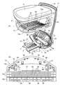
- (A) is a perspective view
- (B) is a side view.
- (A) is the separation perspective view seen from the upper part
- (B) is the separation perspective view seen from the lower part.
- (B) is the isolation
- (B) is a top view of the rear part of a seat inner shell.
- (A) is a separated perspective view of a back frame, a seat inner shell, and an armrest
- (B) is a partial perspective view of a back frame.
- FIG. 11 It is a vertical side view of a substantially central part (the front part is shown separately).
- (A) is sectional drawing seen from the IX-IX staring direction of FIG. 5
- (B) is the isolation
- (A) is the XIIA-XIIA sectional view taken on the line of FIG. 11, and (B) and (C) are partial enlarged views of (A).
- (A) is a cross-sectional view taken along the line XIIIA-XIIIA in FIG. 11,
- (B) to (D) are cross-sectional views without using a cushion layer, (B) corresponds to (A), (C) is 12 corresponds to (B) in FIG. 12, and (D) corresponds to (C) in FIG.
- front and rear and left and right are used to indicate the direction. These front and rear and left and right terms are directions that a person sitting on a rocking chair (hereinafter simply referred to as a chair) faces. It is based on. “Front view” is a state viewed from the direction facing the seated person.
- the chair of the present embodiment is applied to a so-called rotating chair that is frequently used for office work.
- the chair has, as main elements, a leg 1 (gas cylinder) 2 and a leg 1 having branch legs, and an upper end of the leg 2.
- a base 3 fixed to the base 3, a seat 4 disposed above the base 3, and a backrest 5 connected to the base 5 so as to freely tilt backward.
- the left and right armrests 6 can be attached to a chair as an optional item. In FIG. 1A, only one armrest 6 is displayed.
- a caster is provided at the tip of each branch leg constituting the leg 1.
- the base 3 is made of sheet metal, for example, as shown in FIG. 4, has a box shape with an upward opening having a bottom plate, left and right side plates 3 a, and a front plate 3 c, and is long in the front-rear direction.
- the inner bracket 7 (see also FIG. 8) is fixed to the middle of the base 3 by welding, and the upper end of the leg support 2 is fitted from below to the bush 8 fixed to the inner bracket 7 and the bottom plate. Yes.
- left and right side flanges 3b positioned approximately in front of the leg posts 2 are provided at the upper ends of the left and right side plates 3a constituting the base 3, and intermediate metal fittings are provided on the side flanges 3b. 9 is slidably mounted back and forth.
- the seat 4 has a resin seat plate 10 and a cushion 11 disposed on the upper surface thereof, and the seat plate 10 is fixed to the intermediate fitting 9. ing. Accordingly, the seat plate 10 slides back and forth on the base 3 together with the intermediate fitting 9. Needless to say, the cushion is covered with a skin material (not shown) such as a cloth.
- an elevating height adjusting lever 12 is attached to the right side of the base 3, and a locking control lever 13 for restricting the longitudinal movement of the intermediate metal fitting 9 is attached to the left side of the base 3. .
- a rod rod 14 bent in a crank shape is fixed to the elevation adjustment lever 12, and the push valve of the leg column 2 is pushed down by the tip of the rod 14.
- a resin bearing member 15 that holds the rod 14 rotatably is fixed inside the base 3.
- the backrest 5 has a back frame 17 having an opening 16 opened in the front-rear direction, and as shown in FIG. A front back seat 18 and a rear back seat 19 are attached so as to be closed. A thin cushion plate 20 is interposed between the front back seat 18 and the rear back seat 19.
- the back frame 17 is made of resin, but a die-cast product such as aluminum can also be adopted.
- the back frame 17 functions as a strength member that supports the load, and includes a vertically long side member 21 positioned on both the left and right sides of the opening 16, and a horizontally long upper member 22 that is integrally connected to the upper ends of the left and right side members 21.
- the lower member 23 is integrally connected to the lower ends of the left and right side members 21. Although the side member 21 and the upper member 22 are elongate, the lower member 23 has a sturdy structure with a large vertical width.
- a pair of left and right forward protrusions 24 located on the left and right sides of the base 3 are integrally provided at the lower end of the lower member 23.
- a horizontally long slide pin 25 as an example of a first movable guide portion described in the claims is inserted through the rear end portion.
- the slide pin 25 is fitted through a bush 26 ′ in a longitudinal front guide hole 26 provided in the left and right side plate 3 a of the base 3.
- the front guide hole 26 is an example of a first fixed guide portion described in the claims.
- the back frame 17 (or the backrest 4) can be tilted rearward around the slide pin 25, and the front end moves back and forth together with the intermediate fitting 9 via the slide pin 25.
- the forward movement of the intermediate fitting 9 is elastically supported by a coil spring 27 as an example of spring means described in the claims.
- a front and rear groove space 28 opened in the vertical direction and the front is opened by providing left and right forward projecting portions 24.
- the lower member 23 is formed with an upward opening groove 29 having the same lateral width as the groove space 28. Therefore, the inner surface of the groove space 28 and the inner surface of the upward opening groove 29 are flush with each other.
- a rear guide groove 30 curved so as to be concave toward the front upper side in a side view is formed in a state where it is connected to the left and right inner side surfaces of the rear portion of the groove space 28 and the left and right inner side surfaces of the upward opening groove 29.
- a guide protrusion 31 projecting laterally at the rear end of the base 3 is fitted.
- the rear guide groove 30 is an example of a second movable guide part recited in the claims
- the guide protrusion 31 is an example of a second fixed guide part recited in the claims.
- the base end portion (base end portion of the elbow strut) 32 (see FIG. 7A) of the armrest 6 is fitted to the lower surface of the left and right forward projecting portion 24 in the back frame 17.
- An elbow recess 33 is formed.
- a left and right longitudinal reinforcing plate 34 overlaps the left and right forward projecting portions 24 of the back frame 17 from above.
- the reinforcing plate 34 is attached to the rear portion of the seat plate 10 so that it cannot be removed vertically.
- FIG. 6 the intermediate metal fitting 9 is indicated by solid lines in two states, that is, a state where it is attached to the base 3 and a state where it is separated upward.
- the seat 4 is an injection-molded product made of a resin such as polypropylene.
- the front portion 10 b and the rear portion 10 c are sandwiched by a hinge portion 10 a that is freely bent in a side view. It is divided into and.
- the front portion 10b and the rear portion 10c show only the relationship between the front and rear positions with respect to the hinge portion 10a, and do not limit the ratio of the front and rear lengths. That is, in the illustrated example, the front-rear length of the front part 10b is longer than the front-rear length of the rear part 10c. However, the rear part 10c may be longer than the front part 10b, and the front part 10b and the rear part 10c are substantially omitted. The front and rear lengths may be the same. In any case, in order for the rear part 10c to tilt backward with respect to the front part 10b, the rear part 10c must be positioned behind the intermediate fitting 9.
- the hinge portion 10 a has a group of slits 36 that are intermittently extended linearly in the left-right direction, and a plurality of slits 36 that are intermittently extended in a row.
- a large number of flat plate bridge portions 37 are formed by forming a plurality of groups.
- three-dimensional bridge portions 38 are formed at some slits 36 so as to straddle the slits 36.
- a group of these bridge portions 37 and 38 constitutes a hinge portion 10a.
- the front portion 10b of the seat 4 is formed with a large number of ribs 39 that are exposed upward and extend vertically and horizontally.
- dovetail portions 40 that integrally hold the left and right side portions of the intermediate fitting 9 and the side flange 3 b of the base 3 are integrally formed on the lower surface of the front portion 10 b of the seat 4. Yes.
- the dovetail groove 40 opens downward and rearward.
- the intermediate metal fitting 9 is overlapped with the base 3 from above, and a pair of left and right downward pieces 9a is provided at the rear thereof, and a slide pin 25 is inserted into the downward piece 9a.
- a resin-made slide auxiliary body 41 is attached to the side flange 3 b of the base 3 so as not to be able to be displaced forward and backward, and the slide auxiliary body 41 is held by a U-shaped slider 42 facing in front view. is doing.
- the slider 42 is fitted in a notch 43 formed on the side portion of the intermediate fitting 9 so as not to be displaced. Accordingly, the slider 42 moves back and forth together with the intermediate fitting 9.
- grease is applied to the inner surface of the dovetail groove portion 40.
- a window hole 9b is opened up and down along the center line of the intermediate fitting 9, and a downward spring support piece 44 is provided at the rear end edge of the square hole 9b.
- a coil spring 27 is interposed between the spring support piece 44 and the front plate 3 c of the base 3 via front and rear spring receivers 45.
- the spring receiver 45 is fitted on the spring receiving piece 44 and the front plate 3c of the base 3 so as not to be displaced.
- a lock body 46 that swings up and down in conjunction with the turning operation of the above-described locking control lever 13 (see, for example, FIG. 2) is provided in the left portion of the base 3.
- the backrest 5 is limited in a free state in which the backrest can be tilted freely by a full stroke, a locked state in which the backrest is not tilted at all, and a tilt stroke. Switch to the state.
- the rear portion 10 c of the seat 4 is provided with a pair of front and rear support pieces 47 that hold the left and right side portions of the reinforcement plate 34 from below, and the reinforcement plate 34 is configured by the support pieces 47. Is inserted into the ant groove from behind. Further, the advance position of the reinforcing plate 34 is restricted by a support piece 47 located on the front side. As shown in FIG. 6, three female screw holes 48 are formed in the left and right ends of the reinforcing plate 34 by burring and then tapping, and the front and rear support pieces 47 have both ends. Screw holes 49 corresponding to the two female screw holes 48 are opened.
- the front and rear longitudinal first restriction ribs 52 in which the rear engagement claws 50 and the rear stoppers 51 are fitted to the left and right outer portions of the elbow recesses 33 in the forward projecting portion 24 of the back frame 17 so that they cannot be displaced left and right.
- the 2nd control rib 53 is formed.
- a rear engagement hole 54 is formed in the first restriction rib 52 located on the inner side, and the rear engagement claw 50 is hooked and engaged therewith.
- a stopper rib 55 that holds the rear stopper 51 so as not to move backward is formed at a portion between the two regulating ribs 52 and 53.
- a front engagement claw 56 that contacts the front inner surface of the square hole 9 b of the intermediate fitting 9 is provided on the lower surface of the front portion of the front portion 10 b of the seat plate 10. .
- the seat plate 10 is held by the front engaging claws 56 and the rear stopper 51 so as not to move back and forth with respect to the intermediate fitting 9 and the back frame 17, and the front portion 10 b of the seat plate 10 has its dovetail groove 40.
- the rear portion 10c of the seat plate 10 is held so as not to be separated from the back frame 17 by the rear engaging claws 50.
- the rear edge of the rear portion 10c of the seat plate 10 is a wall portion 58 having high rigidity. Further, as shown in FIG. 5, a number of locking claws 59 for hooking a string attached to the periphery of the skin material are formed on the periphery of the lower surface of the seat 4 in a jumping manner.
- the rear portion of the base 3 is a rearward arm portion 3d that is gently inclined in a side view so as to become higher as going backward.
- the inclined shape of the rearward arm portion 3d is caused by the side plate 3a being cut, and the height of the rear end of the rearward arm portion 3d is lower than the height of the upper surface of the front half portion of the base 3.
- the rearward facing arm portion 3d is lower than the lower surface of the seat plate 10.
- a horizontally long shaft 60 is fixed to the rear end of the rearward arm portion 3d in the base 3, and both left and right ends of the shaft 60 protrude outwardly from the left and right sides of the rearward arm portion 3d.
- a protrusion 31 is formed. Therefore, the shaft 60 and the guide protrusion 31 are the same. It is also possible to weld the left and right guide projections 31 to the rearward arm portion 3d without using the shaft 60.
- the front guide hole 26 that is the first fixed guide portion and the guide protrusion 31 that is the second fixed guide portion have substantially the same height.
- the front end 30a of the rear guide groove 30 provided in the back frame 17 is opened downward. For this reason, the rear guide groove 30 of the back frame 17 can be easily fitted into the guide protrusion 31.
- a cover 61 constituting the lower half of the lower member 23 is formed behind the rear guide groove 30. In the unlocked state, the gap 62 between the front end of the cover 61 and the rear end of the base 3 is set to a dimension that a human finger cannot be inserted. Safety can be ensured while allowing
- reinforcing ribs 63 that are long in the front-rear direction are provided on the upper surfaces of the lower member 23 and the forward projecting portion 24 of the back frame 17. Further, the front end of the forward projecting portion 24 is a bearing portion 64 into which the slide pin 25 is fitted.
- the upper half of the lower member 23 in the back frame 17 is substantially the same height as the seat plate 10, and the rear surface 65 of the upper half is in side view.
- the posture is slightly forward tilted with respect to the vertical line.
- the cover part 61 which comprises the lower half part of the lower member 23 inclines so that it may become low as it goes to this side.
- the rear surface of the lower member 23 has a shape that is bent backward and convex in a side view as a whole. For this reason, the lower member 23 does not protrude greatly in the back, and has a clean appearance.
- the cover part 61 moves below the arm part 3 d in the base 3. That is, the cover portion 61 moves forward with the arm portion 3d covered from below. For this reason, the shaft 60 is covered with the cover portion 61 to ensure safety without impairing the locking function or increasing the size of the lower member 23. This is an advantage of the present embodiment.
- Patent Document 3 since the long groove (first cam track) is formed on the inner surface of the slit groove that opens in the front and rear (or up and down) in the back frame, the vertical gap of the slit groove becomes narrower when locking. If a person locks with a finger inserted in the slit groove, there is a risk of pinching the finger.
- the rear end (the rear end of the arm portion) of the base 3 is covered with the cover portion 61 of the lower member 23 both before and after locking. The problem of pinching fingers does not occur, and safety is high.
- the slide auxiliary body 41 (or the side flange 3 a of the base 3) is held on both the left and right sides of the intermediate bracket 9. It is also possible to form a holding part to hold the slide auxiliary body 41 with the holding part. In this case, the intermediate fitting 9 is attached to the base 3 by sliding from the front or the back. Then, since the spring support piece 44 cannot be bent and formed on the intermediate fitting 9, the spring support piece 44 must be welded after the intermediate fitting 9 is mounted on the base 3 as a separate member. Otherwise, the assembly process can be cumbersome.
- the slide auxiliary body 41 is held by a slider 42 which is a separate member from the intermediate fitting 9, and the slider 42 is fitted into the intermediate fitting 9 from the left and right outer sides. If it is adopted, the intermediate metal piece 9 is bent over the base 3 while the spring support piece 44 is bent, and then the slider 42 is fitted, and then the seat plate 10 is fitted into the base 3 and attached. 42 is held unremovable. For this reason, the effort of an assembly process can be reduced, simplifying a structure by bending and forming the spring support piece 41 in the intermediate
- the seat 4 it is possible to configure the seat with an inner shell and an outer shell that supports the seat from below as in Patent Document 1, and when the two-part structure is adopted, the inner shell is bent downward. Since it can be attached to the outer shell in a state, there is an advantage of excellent cushioning properties. However, when a two-part structure is adopted, the cost increases accordingly.
- the seat plate 10 is not simply a single structure, but has several features.
- the front portion 10b secures the necessary strength by increasing the vertical dimension.
- a wall 66 is formed on the outer periphery of the right and left outer portions of the dovetail groove 40.
- the wall 66 is provided with a locking claw 59 for holding the skin material. Thereby, the string for attaching the skin material can be accurately positioned while holding the seat plate 10 with high strength.
- the thickness of the receiving portion 40a on the lower side of the dovetail groove 40 in the front portion 10b of the seat plate 10 is reduced toward the near side, whereas as shown in FIG. In the rear half of the front portion 10b, the height of the rib 39 decreases as it goes backward. For this reason, the front part 10b is generally the same thickness as a whole, but the upper surface is gently inclined backward as it goes backward. For this reason, the seat board 10 has a well-balanced structure, and the fit to the seated person's body is enhanced.
- the rear guide groove 30 When the rear guide groove 30 is employed as the second movable guide portion, the rear guide groove 30 can be configured to have a closed front end (lower end). In this case, when assembling the chair, Since the back frame 17 is inclined and the rear guide groove 30 and the guide protrusion 31 must be fitted together, the smoothness of the assembly work may be lacking.
- the back frame 17 can be set without being tilted in front view, so that it can be easily assembled even if the operator is not skilled.
- a bush may be attached to the rear guide groove 30, or a roller may be employed as the guide protrusion 31.
- the intermediate fitting 9 is set on the base 3, the back frame 17 is fitted into the arm portion 3 d of the base 3, and then the intermediate fitting 9, the base 3, and the back frame 17 with the slide pin 25. And then the seat plate 10 is attached to the base 3 by pushing in from the front.
- the legs widely include those that support the base, and thus can be applied to stationary chairs such as theater chairs.
- the leg and the base may be integrated.
- the leg may be made of a pipe.
- the seat may have a form having an outer shell and an inner shell as in Patent Document 1.
- the base of the embodiment is an integral part as a whole, for example, it is possible to adopt a structure in which a rearward arm portion of another member is welded to a box-shaped main body portion.
- the first and second fixed guide portions and the movable guide portion can be variously embodied.
- the second fixed guide part can be a long hole and the second movable guide part as a pin.
- the first fixed guide portion can be a pin and the first movable guide portion can be a long hole.
- the front guide groove is in a horizontal posture, but the front guide groove can be tilted forward or backward with respect to the horizontal.
- the back frame of the embodiment is a single structure product, for example, the left and right side members and the upper member can be integrated into a single product and connected to the lower member. It is.
- the backrest can adopt a structure in which only one backsheet is stretched on the back frame.
- the front back sheet 18 and the rear back sheet 19 have a mesh-like appearance, and have air permeability, flexibility, and slight translucency. As shown in FIGS. 12 and 13, these back sheets 18 and 19 are fitted with first and second long grooves 71 and 72 provided in the back frame 17 with tape pieces 68 and 69 fixed to the outer peripheral edge thereof. , Held in tension.
- the first long groove 70 is formed on the outer peripheral surfaces of the side member 21 and the upper member 22 and on the front surface of the lower member 23. That is, the first long groove 70 includes a first side long groove 70 a formed on the outer peripheral surface (left and right outward surface) of the side member 21, a first upper long groove 70 b formed on the outer peripheral surface (upper surface) of the lower member 23, It is comprised by the 1st lower long groove 70c formed in the front surface of the member 23.
- the first side long groove 70a and the first upper long groove 70b are continuous with each other, and the first side long groove 70a and the first lower long groove 70c are not continuous. As clearly shown in FIG. 11, the lower end of the first side long groove 70a is located slightly below the left and right ends of the first lower long groove 70c.
- the first lower long groove 70c has one structure and extends to the left and right ends of the lower member 23.
- the front surface of the side member 21 is inclined in a plan view so as to shift backward as it goes to the left and right inside, and the first side long groove 70a is shown in a plan view.
- the posture is substantially parallel to the front surface of the side member 21.
- the front surface of the upper member 22 is generally in a vertical posture
- the first upper long groove 70b is in a posture slightly tilted forward with respect to the vertical line on the vertical side surface (a vertical posture or a backward tilted posture may be used. ).
- the front surface of the lower member 23 is inclined slightly forward with respect to the vertical line.
- the first lower long groove 70c is in a posture slightly tilted backward with respect to the horizontal in a vertical side view, but a horizontal posture or a forward tilting posture can also be adopted.
- the second long groove 71 into which the tape piece 69 of the rear back sheet 19 is fitted is formed in the front surface and each corner portion of each member 21, 22, 23. That is, the second long groove 71 includes a second side long groove 71 a formed on the front surface of the side member 21, a second upper long groove 71 b formed on the front surface of the upper member 22, and a second lower long groove formed on the front surface of the lower member 23. 71c and second corner long grooves 71d formed in four corner portions, and the second long grooves 71a to 71d are separated from each other.
- the second side long groove 71a, the second upper long groove 71b, and the second lower long groove 71c are each divided into a plurality of pieces.
- each of the second side long grooves 71a is oriented in the front-rear direction in a plan view, and the second upper long groove 71b and the second lower long groove 71c are vertically cut. It is in a posture (substantially horizontal posture) facing front and rear in a side view.
- the second corner long groove 71d is also oriented in the front-rear direction when viewed from a cut surface including a diagonal line of the back frame 17.
- the second long grooves 71a to 71d are located on the inner side (closer to the inner periphery of the back frame 17) than the first long grooves 70a to 70c.
- the cushion plate 20 is disposed between the front back seat 18 and the rear back seat 19, but as shown in FIGS. It is also possible to use only the front back seat 18 without arranging.
- the peripheral edge of the cushion plate 20 is overlapped with the back frame 17 in the figure, but the peripheral edge of the cushion plate 20 may be shifted to the inner side of the inner periphery of the back frame 17.
- the second long grooves 71a to 71d are formed on the front surface of the back frame 17, even when only the front back seat 18 is stretched on the back frame 17 without using the cushion plate 20, the second long grooves 71a to 71d are human. Is hardly seen even from the front. Further, when viewed from behind, the second long grooves 71a to 71d are not visible at all. Thus, even when the rear back seat 19 and the cushion plate 20 are not used, the aesthetics are not deteriorated. In addition, the aspect which does not use the cushion board 20 using the front back seat
- both the first lower long groove 70c and the second lower long groove 71c are opened forward.
- each of the first lower long groove 70c is opened downward, and the first lower long groove 70c is opened downward. It is also possible to open it forward.
- a horizontally long auxiliary frame member 23 ' is fixed to the front surface of the lower member 23 in the back frame 17 by means such as screwing, and the auxiliary frame member 23' is fixed to the auxiliary frame member 23 '. It is also possible to form at least the first lower long groove 70c.
- the auxiliary frame member 23 ' is shown only in a state where the first lower long groove 70c is formed. However, when the auxiliary frame member 23' is provided, the first lower long groove 70c and the second lower long groove 71c Both may be formed on the auxiliary frame member 23 '.
- auxiliary frame member 23 ′ By using the auxiliary frame member 23 ′ in this way, it is possible to improve the function of preventing the front back seat 18 from slipping out by providing the lower member 23 with the forward projecting portion 24 and at least the first lower long groove 70 c opened downward. .
- the attachment strength of the rear back seat 19 can be further improved.
- the second lower long groove 71c can be inclined so as to be lowered toward the front while opening forward, and in this case, the function of preventing the rear back seat 19 from dropping out is significantly improved.
- the lower long grooves 70c and 71c can also be formed between the lower member 23 and the auxiliary frame member 23 '.
- a mesh material is attached to the back frame that opens widely in the front and rear, and the body pressure of the seated person is supported by the mesh material.
- a long groove is formed in the back frame, and an edge member such as a tape attached to the outer periphery of the mesh material is inserted into the long groove.
- Japanese Patent Application Laid-Open No. 2009-22498 discloses that dovetail grooves are formed on the outer and inner peripheries of the front and rear mesh material back frames, and the mesh material can be attached using the inner and outer dovetail grooves. Yes.
- a dovetail groove formed on the outer periphery of the back frame is attached with a decorative surface overlapping the front surface of the back frame, while a dovetail groove formed on the inner periphery of the back frame is A mode in which a backup place located behind the decoration place is attached and a filling is interposed between the decoration place and the backup place, and b) an aspect in which the decoration place is simply attached to the dovetail formed on the outer periphery of the back frame, c) It is possible to select and adopt three modes: a mode in which a decoration is simply attached to the dovetail formed on the inner periphery of the back frame.
- JP2009-22498A When the mesh material has a double structure as disclosed in JP2009-22498A, the softness of the body can be improved or the translucency can be cut off by providing a filling between the front and rear mesh materials.
- JP2009-22498A discloses that the back-up ground located on the back side is attached to a dovetail formed on the inner peripheral surface of the back frame, so that only the decorative ground is used without using the back-up ground.
- this decorative area is attached to the outer periphery of the dovetail, the inner periphery of the dovetail can be seen from behind, which may result in poor aesthetics.
- JP 2009-22498 when a seated person leans on the backrest, tension is applied to the back-up or decoration, but when the back-up or decoration is attached to the dovetail opening on the inner periphery of the back frame. Because the direction of the tension and the direction of the dovetail opening are the same, if the degree of constriction of the inner dovetail is small, the members (locking rods) fitted in the inner dovetail can be easily removed. In order to avoid this problem, it is necessary to increase the degree of constriction of the dovetail. However, for example, when the back frame is manufactured by injection molding or die casting, the processing of the dovetail is very troublesome. There is a problem.
- the attachment structure of the back sheet in the present embodiment has been devised for the purpose of improving such a conventional technique.
- a plurality of front and rear mesh-like or other flexible back sheets 18 and 19 can be attached to the back frame 17 that opens back and forth so as to cover the opening.
- the first backsheet (front backsheet) 18 positioned closest to the front of the plurality of backsheets 18 and 19 is attached to at least the outer peripheral surfaces of the side member 21 and the upper member 22.
- the first long groove 70 for the longitudinal direction of the side member 21 and the upper member 22 A back seat (rear) that is formed so as to extend and is positioned at the back of the first back seat 18 among the plurality of back seats 18, 19 at least on the front surfaces of the side member 21 and the upper member 22.
- a second long groove 71 for attaching the back sheet 19 is formed so as to extend in the longitudinal direction of the side member 21 and the upper member 22.
- the second long groove 71 for attaching the second back sheet 19 located behind the first back sheet 18 is formed on the front surface of the back frame 17, the second long groove 71 is used. Even if it is not, it is almost hidden behind the first backsheet 18 from the front and is not visible at all from the back. For this reason, when the 2nd long groove 71 is not used, the problem that an aesthetics deteriorates can be eliminated.
- the back frame 17 can be easily manufactured by injection molding or die casting, and is excellent in generality and versatility.
- the first long groove 70 is open to the outside, and the peripheral portion located on the outer periphery of the side member 21 and the upper member 22 in the first back seat (front back seat) 18 can be seen from the outside.
- the first long grooves 70a and 70b between the side member 21 and the upper member 22 are made continuous, the long grooves 70a between the side member 21 and the upper member 22 are not interrupted without interrupting the peripheral edge of the first back seat (front back seat) 18. , 70b, and can be stored.
- the second back seat (rear back seat) 19 can be firmly positioned by fitting the edge member 59 into the multiple second long grooves (71a to 70c). Can do. For this reason, the second back sheet 19 does not shift during use. It is particularly preferable to form the second long groove 71d in the corner portion of the back frame 17 as in the embodiment because the second back sheet 19 can be held in a diagonal direction of the backrest 5. In addition, it is also possible to arrange
- the present invention can actually be embodied in a chair. Therefore, it can be used industrially.
Landscapes
- Health & Medical Sciences (AREA)
- Dentistry (AREA)
- General Health & Medical Sciences (AREA)
- Chairs Characterized By Structure (AREA)
- Chairs For Special Purposes, Such As Reclining Chairs (AREA)
Abstract
Fauteuil, comprenant une base (3) fixée à l'extrémité supérieure d'un support de pied (2); un siège (4) étant monté sur la base (3) de façon à pouvoir coulisser vers l'avant et vers l'arrière en raison d'une broche coulissante (25). Un dossier (5) est doté d'une structure dans laquelle un maillage siège arrière est étiré sur un cadre de dossier (17) qui est ouvert à l'avant et à l'arrière, et l'extrémité avant du cadre de dossier (17) est reliée à la broche de coulissement (25). Une protubérance de guidage (31) prévue sur l'extrémité arrière de la base (3) est ajustée dans une rainure (30) de guidage arrière formée dans le cadre de dossier (17). En raison du fait que la rainure (30) de guidage arrière et la protubérance de guidage (31) sont positionnées plus bas que la surface supérieure du siège (4), le cadre arrière (17) présente une grande ouverture (16) mais peut être incliné vers l'arrière sans difficulté.
Applications Claiming Priority (2)
| Application Number | Priority Date | Filing Date | Title |
|---|---|---|---|
| JP2012067767A JP5977053B2 (ja) | 2012-03-23 | 2012-03-23 | ロッキング椅子 |
| JP2012-067767 | 2012-03-23 |
Publications (1)
| Publication Number | Publication Date |
|---|---|
| WO2013141237A1 true WO2013141237A1 (fr) | 2013-09-26 |
Family
ID=49222694
Family Applications (1)
| Application Number | Title | Priority Date | Filing Date |
|---|---|---|---|
| PCT/JP2013/057815 WO2013141237A1 (fr) | 2012-03-23 | 2013-03-19 | Fauteuil à bascule |
Country Status (3)
| Country | Link |
|---|---|
| JP (1) | JP5977053B2 (fr) |
| TW (1) | TW201345460A (fr) |
| WO (1) | WO2013141237A1 (fr) |
Cited By (1)
| Publication number | Priority date | Publication date | Assignee | Title |
|---|---|---|---|---|
| GB2552732A (en) * | 2016-08-02 | 2018-02-07 | Actiu Berbegal Y Formas S A | Device for tilting the backrest of office chairs |
Families Citing this family (3)
| Publication number | Priority date | Publication date | Assignee | Title |
|---|---|---|---|---|
| JP6353213B2 (ja) * | 2013-11-11 | 2018-07-04 | 株式会社イトーキ | ロッキング椅子 |
| JP6650094B2 (ja) * | 2015-10-26 | 2020-02-19 | コクヨ株式会社 | 椅子 |
| JP7356779B2 (ja) * | 2019-10-11 | 2023-10-05 | タカノ株式会社 | 椅子の背凭れ構造及び椅子 |
Citations (4)
| Publication number | Priority date | Publication date | Assignee | Title |
|---|---|---|---|---|
| JPH05123228A (ja) * | 1991-11-08 | 1993-05-21 | Chitose Kk | 背凭れ付き椅子 |
| JP2004024702A (ja) * | 2002-06-27 | 2004-01-29 | Itoki Crebio Corp | 椅子 |
| JP2008295515A (ja) * | 2007-05-29 | 2008-12-11 | Itoki Corp | ロッキング椅子 |
| JP2011161123A (ja) * | 2010-02-15 | 2011-08-25 | Itoki Corp | 椅子 |
-
2012
- 2012-03-23 JP JP2012067767A patent/JP5977053B2/ja active Active
-
2013
- 2013-03-19 WO PCT/JP2013/057815 patent/WO2013141237A1/fr active Application Filing
- 2013-03-22 TW TW102110228A patent/TW201345460A/zh unknown
Patent Citations (4)
| Publication number | Priority date | Publication date | Assignee | Title |
|---|---|---|---|---|
| JPH05123228A (ja) * | 1991-11-08 | 1993-05-21 | Chitose Kk | 背凭れ付き椅子 |
| JP2004024702A (ja) * | 2002-06-27 | 2004-01-29 | Itoki Crebio Corp | 椅子 |
| JP2008295515A (ja) * | 2007-05-29 | 2008-12-11 | Itoki Corp | ロッキング椅子 |
| JP2011161123A (ja) * | 2010-02-15 | 2011-08-25 | Itoki Corp | 椅子 |
Cited By (2)
| Publication number | Priority date | Publication date | Assignee | Title |
|---|---|---|---|---|
| GB2552732A (en) * | 2016-08-02 | 2018-02-07 | Actiu Berbegal Y Formas S A | Device for tilting the backrest of office chairs |
| GB2552732B (en) * | 2016-08-02 | 2018-10-17 | Actiu Berbegal Y Formas S A | Device for tilting the backrest of office chairs |
Also Published As
| Publication number | Publication date |
|---|---|
| JP5977053B2 (ja) | 2016-08-24 |
| JP2013198564A (ja) | 2013-10-03 |
| TW201345460A (zh) | 2013-11-16 |
Similar Documents
| Publication | Publication Date | Title |
|---|---|---|
| JP5514509B2 (ja) | ロッキング椅子 | |
| JP6326769B2 (ja) | 椅子 | |
| WO2013141237A1 (fr) | Fauteuil à bascule | |
| JP6215659B2 (ja) | 椅子 | |
| JP5339548B2 (ja) | 背もたれ付き椅子 | |
| JP2008302082A (ja) | ロッキング椅子 | |
| JP2008302062A (ja) | ロッキング椅子 | |
| JP3967150B2 (ja) | 椅子 | |
| JP6008528B2 (ja) | 椅子の背もたれ | |
| JP2007152145A (ja) | 椅子 | |
| JP2007175520A (ja) | 椅子 | |
| JP6518073B2 (ja) | 椅子 | |
| JP7414394B2 (ja) | 椅子 | |
| JP2019083956A (ja) | 椅子 | |
| JP2017086376A (ja) | 椅子 | |
| JP4936270B2 (ja) | 椅子 | |
| US10334953B2 (en) | Furniture, load support member for chair, and chair | |
| JP6326770B2 (ja) | 椅子 | |
| JP2015093087A (ja) | 椅子 | |
| JP6358166B2 (ja) | 椅子 | |
| JP7000516B2 (ja) | 椅子の背もたれ | |
| JP7448354B2 (ja) | 椅子 | |
| JP7479147B2 (ja) | 椅子 | |
| JP2008154937A (ja) | 椅子 | |
| JP2015093090A (ja) | 椅子 |
Legal Events
| Date | Code | Title | Description |
|---|---|---|---|
| 121 | Ep: the epo has been informed by wipo that ep was designated in this application |
Ref document number: 13763561 Country of ref document: EP Kind code of ref document: A1 |
|
| NENP | Non-entry into the national phase |
Ref country code: DE |
|
| 122 | Ep: pct application non-entry in european phase |
Ref document number: 13763561 Country of ref document: EP Kind code of ref document: A1 |