WO2013141188A1 - Dispositif d'injection de médicament - Google Patents
Dispositif d'injection de médicament Download PDFInfo
- Publication number
- WO2013141188A1 WO2013141188A1 PCT/JP2013/057590 JP2013057590W WO2013141188A1 WO 2013141188 A1 WO2013141188 A1 WO 2013141188A1 JP 2013057590 W JP2013057590 W JP 2013057590W WO 2013141188 A1 WO2013141188 A1 WO 2013141188A1
- Authority
- WO
- WIPO (PCT)
- Prior art keywords
- gasket
- pusher
- injection device
- drug injection
- cylindrical body
- Prior art date
Links
Images


Classifications
-
- A—HUMAN NECESSITIES
- A61—MEDICAL OR VETERINARY SCIENCE; HYGIENE
- A61M—DEVICES FOR INTRODUCING MEDIA INTO, OR ONTO, THE BODY; DEVICES FOR TRANSDUCING BODY MEDIA OR FOR TAKING MEDIA FROM THE BODY; DEVICES FOR PRODUCING OR ENDING SLEEP OR STUPOR
- A61M5/00—Devices for bringing media into the body in a subcutaneous, intra-vascular or intramuscular way; Accessories therefor, e.g. filling or cleaning devices, arm-rests
- A61M5/178—Syringes
- A61M5/31—Details
- A61M5/315—Pistons; Piston-rods; Guiding, blocking or restricting the movement of the rod or piston; Appliances on the rod for facilitating dosing ; Dosing mechanisms
- A61M5/31511—Piston or piston-rod constructions, e.g. connection of piston with piston-rod
- A61M5/31515—Connection of piston with piston rod
-
- A—HUMAN NECESSITIES
- A61—MEDICAL OR VETERINARY SCIENCE; HYGIENE
- A61B—DIAGNOSIS; SURGERY; IDENTIFICATION
- A61B17/00—Surgical instruments, devices or methods, e.g. tourniquets
- A61B17/56—Surgical instruments or methods for treatment of bones or joints; Devices specially adapted therefor
- A61B17/58—Surgical instruments or methods for treatment of bones or joints; Devices specially adapted therefor for osteosynthesis, e.g. bone plates, screws, setting implements or the like
- A61B17/88—Osteosynthesis instruments; Methods or means for implanting or extracting internal or external fixation devices
- A61B17/8802—Equipment for handling bone cement or other fluid fillers
- A61B17/8805—Equipment for handling bone cement or other fluid fillers for introducing fluid filler into bone or extracting it
- A61B17/8819—Equipment for handling bone cement or other fluid fillers for introducing fluid filler into bone or extracting it characterised by the introducer proximal part, e.g. cannula handle, or by parts which are inserted inside each other, e.g. stylet and cannula
-
- A—HUMAN NECESSITIES
- A61—MEDICAL OR VETERINARY SCIENCE; HYGIENE
- A61B—DIAGNOSIS; SURGERY; IDENTIFICATION
- A61B17/00—Surgical instruments, devices or methods, e.g. tourniquets
- A61B17/56—Surgical instruments or methods for treatment of bones or joints; Devices specially adapted therefor
- A61B17/58—Surgical instruments or methods for treatment of bones or joints; Devices specially adapted therefor for osteosynthesis, e.g. bone plates, screws, setting implements or the like
- A61B17/88—Osteosynthesis instruments; Methods or means for implanting or extracting internal or external fixation devices
- A61B17/8802—Equipment for handling bone cement or other fluid fillers
- A61B17/8805—Equipment for handling bone cement or other fluid fillers for introducing fluid filler into bone or extracting it
- A61B17/8822—Equipment for handling bone cement or other fluid fillers for introducing fluid filler into bone or extracting it characterised by means facilitating expulsion of fluid from the introducer, e.g. a screw pump plunger, hydraulic force transmissions, application of vibrations or a vacuum
-
- A—HUMAN NECESSITIES
- A61—MEDICAL OR VETERINARY SCIENCE; HYGIENE
- A61B—DIAGNOSIS; SURGERY; IDENTIFICATION
- A61B17/00—Surgical instruments, devices or methods, e.g. tourniquets
- A61B17/56—Surgical instruments or methods for treatment of bones or joints; Devices specially adapted therefor
- A61B17/58—Surgical instruments or methods for treatment of bones or joints; Devices specially adapted therefor for osteosynthesis, e.g. bone plates, screws, setting implements or the like
- A61B17/88—Osteosynthesis instruments; Methods or means for implanting or extracting internal or external fixation devices
- A61B17/8802—Equipment for handling bone cement or other fluid fillers
- A61B17/8805—Equipment for handling bone cement or other fluid fillers for introducing fluid filler into bone or extracting it
- A61B17/8825—Equipment for handling bone cement or other fluid fillers for introducing fluid filler into bone or extracting it characterised by syringe details
-
- A—HUMAN NECESSITIES
- A61—MEDICAL OR VETERINARY SCIENCE; HYGIENE
- A61M—DEVICES FOR INTRODUCING MEDIA INTO, OR ONTO, THE BODY; DEVICES FOR TRANSDUCING BODY MEDIA OR FOR TAKING MEDIA FROM THE BODY; DEVICES FOR PRODUCING OR ENDING SLEEP OR STUPOR
- A61M5/00—Devices for bringing media into the body in a subcutaneous, intra-vascular or intramuscular way; Accessories therefor, e.g. filling or cleaning devices, arm-rests
- A61M5/178—Syringes
- A61M5/31—Details
- A61M2005/3123—Details having air entrapping or venting means, e.g. purging channels in pistons
-
- A—HUMAN NECESSITIES
- A61—MEDICAL OR VETERINARY SCIENCE; HYGIENE
- A61M—DEVICES FOR INTRODUCING MEDIA INTO, OR ONTO, THE BODY; DEVICES FOR TRANSDUCING BODY MEDIA OR FOR TAKING MEDIA FROM THE BODY; DEVICES FOR PRODUCING OR ENDING SLEEP OR STUPOR
- A61M5/00—Devices for bringing media into the body in a subcutaneous, intra-vascular or intramuscular way; Accessories therefor, e.g. filling or cleaning devices, arm-rests
- A61M5/178—Syringes
- A61M5/1782—Devices aiding filling of syringes in situ
Definitions
- the present invention relates to a drug injecting device used for injecting a drug of a high viscosity fluid into an injection space.
- PVP percutaneous vertebroplasty
- a filler that hardens with time is injected through a bone biopsy needle inserted into a fractured vertebral body for a vertebral body compression fracture caused by osteoporosis or cancer.
- the filler for example, calcium phosphate bone cement or polymethylmethacrylate bone cement (hereinafter, also simply referred to as “bone cement”) having X-ray contrast properties is used.
- bone cement has a very high viscosity, and in the vertebra filled with the bone cement, the pressure loss is very large due to the spongy material, etc., and at the time of injection, a small amount may be injected at a high pressure of 3 MPa or more. .
- an injection tool a configuration is used in which bone cement is discharged while applying a high pressure by a general piston type or feed screw type syringe.
- a feed screw type injection device including a high pressure seal at a plunger tip, and an air escape path in the high pressure seal (see, for example, US Pat. No. 7,604,618).
- the rate at which air rises in the drug is low, and it takes a considerable amount of time to discharge the air. Also, if the time required to remove air is long, drugs such as bone cement start to harden.
- U.S. Pat. No. 7,604,618 discloses that when the plunger is first inserted into the chamber, only dimples are used as an air escape path, and it is not disclosed to remove the mixed air when the medicine is filled. .
- the present invention has been made in consideration of the above-mentioned problems, and is capable of easily discharging air mixed in a cylinder when filling a drug, and reducing the time required for discharging the drug.
- the purpose is to provide.
- a drug injection device includes a cylindrical body having a drug discharge port at the tip and filled with a drug, and a pusher inserted into a hollow portion of the cylindrical body.
- a hollow gasket provided on the outer periphery of the pusher and slidable in a liquid-tight manner in the tubular body, and the medicine is formed by the tubular body, the pusher, and the gasket.
- a filling chamber is formed, and when the pusher is advanced in the cylindrical body, the air inside the medicine filling chamber is discharged between the outer peripheral portion of the tip of the pusher and the inner peripheral portion of the gasket.
- the discharge passage is characterized in that the pusher and the gasket are in close contact with each other and closed when the pusher is retracted in the cylindrical body.
- the gasket is loosely fitted at the outer periphery of the tip of the pusher, so that no force is applied to the pusher, and a gap is left between the pusher and the gasket to discharge.
- the passage is opened, the air mixed in the filling chamber when the medicine is filled can be discharged to the outside by using the discharge passage, so that the time required for discharging the mixed air can be shortened.
- At least a portion of the gasket that comes into close contact with the pusher when the pusher is retracted in the cylindrical body may be made of an elastic material.
- annular engagement convex portion that bulges radially outward and extends in the circumferential direction is provided on the outer peripheral portion of the pusher, and on the inner peripheral portion of the gasket,
- An annular recess extending in the circumferential direction is provided with an engagement recess that engages with the engagement protrusion, and the engagement protrusion has a tapered outer periphery whose outer diameter decreases in the proximal direction.
- the engagement recess is provided with a tapered inner peripheral portion whose inner diameter decreases in the proximal direction, and the tapered outer peripheral portion is moved when the pusher is moved in the proximal direction.
- the tapered inner periphery may be in close contact with each other. Since the taper outer periphery of the pusher and the taper inner periphery of the gasket are in close contact with each other, air is prevented from flowing into the cylindrical body through the discharge passage. It is possible to smoothly perform the operation of sucking from the inside.
- the resistance between the gasket and the cylindrical body when the pusher is moved in the proximal direction is such that the tapered outer peripheral portion of the pusher is tapered on the gasket. It is good that it is larger than the resistance between the pusher and the gasket that is added when contacting and closely contacting the inner periphery of the shape. Accordingly, the discharge passage is appropriately closed along with the movement of the pusher in the proximal direction, and the operation of sucking the medicine from the distal end side of the cylindrical body can be performed more smoothly.
- the gasket may have an annular seal portion that can be in close contact with the inner peripheral surface of the cylindrical body.
- the gasket is provided with at least one side hole that communicates the hollow portion of the gasket with the outer peripheral portion of the gasket, and the inner end of the side hole is With respect to the axial position of the gasket, it is located on the tip side of the portion that is in close contact with the pusher when the pusher is retracted in the cylindrical body, and the outer end of the side hole is the axial position of the gasket. With respect to the above, it is preferable to be located on the tip side of the seal portion.
- the mixed air in the gap between the liquid level of the drug in the cylindrical body and the front end surface of the gasket, between the inner peripheral surface of the cylindrical body and the outer peripheral surface of the gasket, can be sequentially passed to be discharged to the outside, and therefore, the mixed air bag path can be eliminated.
- the pusher is configured to be displaced in the axial direction as it rotates about the axis with respect to the cylindrical body, and the gasket is rotated about the axis with respect to the pusher. It is preferable that the relative rotation is possible.
- the tip surface of the gasket is preferably formed in a taper shape in which the inner diameter increases perpendicularly to the axis of the pusher or toward the tip. According to the shape of the front end face of these gaskets, the gap between the liquid level of the drug in the cylindrical body and the front end face of the gasket can be filled, and therefore, the air intake path can be eliminated.
- the discharge passage may be closed when the pusher and the gasket come into close contact with each other when the gasket presses the drug in the cylindrical body.
- the medicine is prevented from leaking in the proximal direction through the discharge passage.
- the outer peripheral portion of the distal end of the pusher is provided with a tapered outer peripheral portion whose outer diameter increases in the proximal direction, and the gasket has an inner diameter in the proximal direction.
- An increasing tapered inner peripheral portion is provided, and in the pusher, a step portion due to a change in outer diameter is provided on the proximal end side with respect to the tapered outer peripheral portion, and the pusher is operated to move in the distal direction.
- the tapered outer peripheral portion and the tapered inner peripheral portion are in close contact with each other, and the proximal end surface of the gasket and the distal end surface of the stepped portion of the pusher are preferably in close contact with each other.
- the resistance between the gasket and the cylindrical body when the pusher is moved in the distal direction is such that the tapered outer peripheral portion of the pusher is the taper of the gasket. It is good that it is smaller than the resistance between the said pusher added when contacting and closely contacting a shape inner peripheral part and the said gasket.
- the discharge passage may extend in the circumferential direction between the pusher and the gasket.
- the present invention it is possible to easily discharge the air mixed in the cylinder when filling the medicine, and it is possible to shorten the time required for discharging the air.
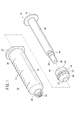
- FIG. 1 is an exploded perspective view of a pharmaceutical injection device 10 according to an embodiment of the present invention.
- FIG. 2 is a perspective view of the pharmaceutical injection device 10 shown in FIG. FIG.
- the direction toward the distal end is defined as the distal direction
- the direction toward the proximal end is defined as the proximal direction
- the drug injection device 10 is an instrument used for discharging a drug when a drug of a high-viscosity fluid is injected into a desired injection space.
- bone cement is put into bone in percutaneous vertebroplasty. Used to inject.
- the drug include bone cements such as calcium phosphate bone cement (CPC) and polymethyl methacrylate (PMMA) bone cement, and calcium phosphate ceramics, alumina ceramics, zirconia ceramics, and titanium.
- Granules made of inorganic materials can also be used. That is, the drug injection device 10 is used for injecting a drug having a viscosity of about 1000 cP (centipoise) to 100000 cP, preferably about 5000 cP, for example.
- the drug injection device 10 includes a cylindrical body 12, a pusher 14, and a gasket 16.
- the cylindrical body 12 includes a body portion 18 having a lumen (hollow portion) extending in the axial direction, a distal end tube portion 20 projecting from the distal end portion of the body portion 18 in the distal direction, and a proximal end of the body portion 18. And a flange portion 22 protruding outward (radially outward) from the portion.
- the body part 18, the distal end pipe part 20, and the flange part 22 are integrally formed.
- the body portion 18 is formed in a hollow cylindrical shape having an inner diameter and an outer diameter that are substantially constant along the axial direction, and the inner surface on the distal end side thereof is formed in a tapered shape, and is opened at the distal end and coupled to the distal end pipe portion 20. Yes. Further, a scale 24 indicating the amount of medicine is displayed on the outer peripheral surface of the body portion 18.
- the tip tube portion 20 forms a medicine discharge port and is configured as a luer connector.
- a lock portion 28 that protrudes in the axial direction from the distal end portion of the body portion 18 concentrically with the distal end tube portion 20 and has an internal thread portion 26 formed on the inner peripheral surface is provided.
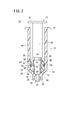
- the distal end tube portion 20 and the lock portion 28 can be connected to a nozzle 30 (see FIG. 3) used for filling the medicine and an injection needle 32 (see FIGS. 4 and 5) used for injecting the medicine. .
- a medicine filling chamber 34 (see FIG. 3) for filling medicine by a space surrounded by the cylindrical body 12, the pusher 14 and the gasket 16. It is formed.
- the constituent material of the cylindrical body 12 is not particularly limited.
- polyolefin such as polypropylene, polyethylene, cyclic polyolefin, and polymethylpentene 1 polyester, nylon, polycarbonate, polymethyl methacrylate (PMMA), and polyetherimide (PEI).
- PEI polyetherimide
- It may be formed of a resinous material such as polyethersulfone, polyetheretherketone (PEEK), fluororesin, polyphenylene sulfide (PPS), polyacetal resin (POM), a metallic material such as stainless steel, glass or the like.
- PES polyetheretherketone
- PPS polyphenylene sulfide
- POM polyacetal resin
- metallic material such as stainless steel, glass or the like.
- the constituent material of the cylindrical body 12 is substantially transparent in order to ensure internal visibility.
- it is preferable that it has strength, elasticity and chemical resistance that can withstand high pressure.
- the pusher 14 is a plunger that is inserted into the hollow portion of the cylindrical body 12, and a gasket 16 is provided on the outer peripheral portion of the tip thereof. As shown in FIG. 2, when the pusher 14 advances in the cylindrical body 12, the air in the medicine filling chamber 34 is blown between the tip outer peripheral part of the pusher 14 and the inner peripheral part of the gasket 16.
- a discharge passage 56 is provided for discharging. In the illustrated example, the discharge passage 56 extends in the circumferential direction between the small diameter portion 38 of the pusher 14 and the gasket 16 and has an annular shape. The discharge passage 56 is closed by the close contact between the pusher 14 and the gasket 16 when the gasket 16 presses the medicine in the cylindrical body 12.
- the pusher 14 includes, for example, a head portion 36 that is a distal end portion, a small diameter portion 38 that constitutes a distal end side, a large diameter portion 40 that constitutes a proximal end side, and a flange portion 42 provided on the proximal end portion.
- the outer peripheral edge of the distal end of the head portion 36 is formed in a tapered shape, and when the pusher 14 advances to the maximum in the cylindrical body 12, it is substantially fitted to the tapered inner surface of the distal end portion of the body portion 18.
- the small diameter portion 38 has an annular engagement convex portion 44 projecting outward on the outer periphery thereof, and the engagement convex portion 44 is formed integrally with the small diameter portion 38.
- the head portion 36, the small diameter portion 38, the large diameter portion 40, and the flange portion 42 are integrally formed. Alternatively, the small diameter portion 38 and the large diameter portion 40 may be detachable.
- the outer diameter of the small diameter portion 38 of the pusher 14 is slightly smaller than the inner diameter of the through hole 46 of the gasket 16, and the axial length of the small diameter portion 38 is the length of the inner surface of the gasket 16 in the axial direction. That is, the length may be the same as the length of the through hole 46 in the gasket 16 in the axial direction.
- the outer diameter of the large-diameter portion 40 of the pusher 14 is smaller than the inner diameter of the cylindrical body 12.
- the outer diameter of the engaging convex portion 44 on the small diameter portion 38 is slightly smaller than the inner diameter of the engaging concave portion 48 formed on the inner surface of the gasket 16.
- the small-diameter portion 38 and the engagement convex portion 44 are fitted in the gasket 16 with a slight gap, and this gap becomes the discharge passage 56.
- the axial length of the head portion 36, the small diameter portion 38 and the large diameter portion 40 is at least longer than the axial length of the hollow portion of the body portion 18. Further, the outer diameter of the engaging convex portion 44 on the small diameter portion 38 is larger than the inner diameter of the through hole 46 of the gasket 16.
- the flange portion 42 is a portion that the user presses with a finger (for example, thumb) when pressing the pusher 14 in the distal direction, and has an appropriate size so that it can be easily pressed. Thereby, for example, when the index finger and the middle finger are put on the flange portion 22 of the cylindrical body 12 and the flange portion 42 is pressed with the thumb, the pusher 14 is moved in the distal direction with respect to the cylindrical body 12. Operation can be performed easily.
- a finger for example, thumb
- the engaging convex portion 44 is an annular engaging portion that bulges outward in the radial direction and extends in the circumferential direction at the outer peripheral portion of the tip of the pusher 14, and has an outwardly convex trapezoidal sectional shape (FIG. 2). Reference) may be formed, or it may be formed in a rectangular cross-section that is convex outward.
- the engagement convex portion 44 includes, for example, a first tapered outer peripheral portion 58 whose outer diameter increases in the proximal direction on the distal end side, and a second tapered outer periphery whose outer diameter decreases in the proximal direction.
- a portion 60 is provided on the proximal end side, and a parallel outer peripheral portion 61 having an outer peripheral surface parallel to the axial direction is provided between the first tapered outer peripheral portion 58 and the second tapered outer peripheral portion 60.
- the constituent material of the pusher 14 can be selected from those exemplified as the constituent material of the cylindrical body 12 described above.
- the small-diameter portion 38 and the engaging convex portion 44 are made of a material different from that of other members, for example, olefin elastomer, styrene elastomer, polyester elastomer, polyurethane elastomer, or vulcanization of silicone rubber, butyl rubber, fluorine rubber, or the like. You may form with elastic materials, such as rubber
- the gasket 16 includes a gasket main body 45 and a seal portion 50 provided on the outer peripheral portion of the tip of the pusher 14, and the seal portion 50 is provided in an annular shape on the outer peripheral surface of the gasket main body 45.
- the gasket main body 45 has a cylindrical shape having a through-hole 46 that penetrates linearly in the axial direction.
- the through-hole 46 is an annular shape that fits with the engagement convex portion 44 on the small-diameter portion 38 of the pusher 14.
- An engaging recess 48 is provided.
- the front end surface 52 of the gasket body 45 is formed in a tapered shape whose outer diameter decreases toward the front end direction, and is substantially fitted to the inner surface of the front end portion of the body portion 18 when the gasket 16 is advanced most in the cylindrical body 12. Is possible.
- the base end surface 68 of the gasket body 45 may be a surface perpendicular to the axial direction, for example.
- the outer diameter of the gasket body 45 is slightly smaller than the inner diameter
- the engagement recess 48 is an annular groove formed on the inner peripheral surface of the through hole 46 and extending in the circumferential direction, and is preferably formed on the outer side with a concave trapezoidal cross-sectional shape (see FIG. 2). Alternatively, it may be formed with a concave rectangular cross-sectional shape on the outside.
- the engaging recess 48 includes, for example, a first tapered inner peripheral portion 62 whose inner diameter increases in the proximal direction on the distal end side, and a second tapered inner peripheral portion whose inner diameter decreases in the proximal direction. 64 is provided on the base end side, and further, a parallel inner peripheral portion 65 having an inner peripheral surface parallel to the axial direction is provided between the first tapered inner peripheral portion 62 and the second tapered inner peripheral portion 64.
- the seal portion 50 has an outer diameter slightly larger than the inner diameter of the cylindrical body 12 and is an annular one that can be in close contact with the inner peripheral surface of the cylindrical body 12, and is formed from the elastic material described above. Good.
- the seal portion 50 is provided on the outer peripheral surface of the gasket main body 45, and slides in the axial direction together with the gasket main body 45 while being in close contact with the inner peripheral surface of the cylindrical body 12. Can be securely held and slidability can be improved.
- the seal portion 50 may be, for example, a component such as a silicone O-ring that is fitted to an annular groove portion 54 formed in the circumferential direction on the outer peripheral surface of the gasket main body 45 and independent from the gasket main body 45. Alternatively, it may be formed integrally with the gasket body 45.
- the outer diameter of the gasket body 45 is set to be slightly larger than the inner diameter of the cylindrical body 12, and the outer peripheral surface of the gasket main body 45 is in close contact with the inner peripheral surface of the cylindrical body 12. By doing so, the liquid tightness of the gasket 16 may be maintained.
- the constituent material of the gasket main body 45 may be selected from those exemplified as the constituent material of the cylindrical body 12 described above, or may be selected from the elastic material described above.
- 45 proximal end surfaces 68 are formed of an elastic material.
- a portion that is in close contact when the pusher 14 is pulled, for example, the second tapered inner peripheral portion 64 of the engaging recess 48 may be formed of an elastic material.
- the pusher 14 and the gasket 16 are separate members formed independently from each other, but the head portion 36 and the small diameter portion 38 of the pusher 14 are moved in the axial direction into the through hole 46 of the gasket 16. It becomes possible to use the medicine injection device 10 only after the insertion.
- the head portion 36 of the pusher 14 and the tip end surface 52 of the gasket 16 have the same inclination angle, and the head portion 36 of the pusher 14 protrudes from the tip end surface 52 of the gasket 16 to form one conical surface.
- the conical surface is substantially fitted to the inner surface of the front end portion of the body portion 18.
- the gasket 16 is disposed so as to be relatively rotatable around the axis with respect to the pusher 14, and these gaps are disposed in the medicine filling chamber 34. It becomes a discharge passage 56 for discharging the air inside.
- the head portion 36 of the pusher 14 and the front end surface 52 of the gasket 16 are formed in the body portion 18 of the cylindrical body 12.
- a medicine filling chamber 34 for filling medicine is formed between the body portion 18 and the inner surface of the distal end portion of the body portion 18.
- the discharge passage 56 is opened. The air can pass through the medicine filling chamber 34 and the base end side through the. Further, as shown in FIG.
- the drug injection device 10 is basically configured as described above. Hereinafter, the operation and effect of the drug injection device 10 using the drug injection device 10 will be described. Will be described as an example.
- the gasket 16 is attached to the pusher 14 and the pusher 14 and the gasket 16 are inserted into the cylindrical body 12 so that the drug injection device 10 can be used. To do.
- the medicine 78 is filled using the medicine injection tool 10
- the pusher 14 and the gasket 16 are deeply pushed into the cylindrical body 12, and the head portion 36 of the pusher 14 and the front end surface 52 of the gasket 16 are formed in the body portion. 18 is in contact with the inner surface of the tip portion.
- the nozzle 30 is connected to the distal end tube portion 20 of the cylindrical body 12 of the drug injection device 10 in this state (see FIG. 3).
- the nozzle 30 includes a male threaded portion 70 on the proximal end side, and is coupled to the distal end tube portion 20 by screwing the male threaded portion 70 with the female threaded portion 26 of the distal end tube portion 20.
- the tip of the nozzle 30 is immersed under the liquid level of the medicine 78 prepared in the container 80, and the pusher 14 is pulled in the proximal direction with respect to the cylindrical body 12 in this state.
- the pusher 14 since the seal portion 50 of the gasket 16 is in close contact with the inner peripheral surface of the cylindrical body 12, first, the pusher 14 moves slightly in the proximal direction with respect to the gasket 16.
- the second tapered outer peripheral portion 60 of the engaging convex portion 44 of the small diameter portion 38 is in contact with and closely contacts the second tapered inner peripheral portion 64 of the engaging concave portion 48 of the gasket 16. The gap between 14 and the gasket 16 is closed, and the discharge passage 56 is closed.
- the pusher 14 is further pulled in the proximal direction, and the gasket 16 slides in the proximal direction in accordance with the movement of the pusher 14. Further, since the inside of the medicine filling chamber 34 of the cylindrical body 12 is in a vacuum state, a desired amount of medicine 78 is brought into the medicine filling chamber 34 as the pusher 14 and the gasket 16 move in the proximal direction. Aspirated and filled. Since the nozzle 30 is removed when the drug 78 is injected, it is preferable to suck the drug 78 into the drug filling chamber 34 without leaving the drug 78 in the nozzle 30.
- the second tapered outer peripheral portion 60 of the engaging convex portion 44 of the small diameter portion 38 is changed to the second tapered inner peripheral portion of the engaging concave portion 48 of the gasket 16. It is preferable that the gasket 16 does not slide relative to the body portion 18 until the gap between the pusher 14 and the gasket 16 is closed and the discharge passage 56 is closed.
- the resistance between the gasket 16 and the body portion 18 is such that the second tapered outer peripheral portion 60 of the engaging convex portion 44 of the small diameter portion 38 is the second tapered inner peripheral portion 64 of the engaging concave portion 48 of the gasket 16. It is larger than the resistance between the pusher 14 and the gasket 16 which is added when contacting and closely contacting with each other.
- the medicine 78 and the air mixed at the time of filling are put in the medicine filling chamber 34 of the cylindrical body 12 (see FIG. 3).
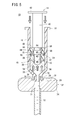
- the injection needle 32 is directly connected to the distal end tube portion 20 of the cylindrical body 12 of the drug injection device 10 in this state (see FIG. 4).
- the injection needle 32 is made of, for example, a hollow puncture needle 72 made of a metal material, and made of, for example, a resin material fixed to a proximal end portion of the puncture needle 72. And a handle 74.
- An injection port 76 communicating with the lumen (hollow part) of the puncture needle 72 is provided at the upper portion of the handle 74, and a male screw portion 71 is provided on the outer peripheral surface of the injection port 76.
- the injection needle 32 is connected to the distal end pipe part 20 by screwing the male thread part 71 with the female thread part 26 of the distal end pipe part 20.
- the injection needle 32 when injecting a drug under CT fluoroscopy or X-ray fluoroscopy, the injection needle 32 is in a state where the operator's (user's) hand is retracted outside the X irradiation region.
- the distal end tube portion 20 and the injection needle 32 may be coupled via an extension tube.
- the injection port 76 of the injection needle 32 and the distal end tube portion 20 of the cylindrical body 12 are connected to the extension tube. Connect through.
- the pusher 14 is pushed into the cylindrical body 12 in the distal direction.
- the second tapered outer peripheral portion 60 of the engaging convex portion 44 of the small diameter portion 38 is separated from the second tapered inner peripheral portion 64 of the engaging concave portion 48 of the gasket 16, and the pusher 14 and A gap between the gaskets 16 is opened, and the discharge passage 56 is opened. Via this discharge passage 56, the air mixed in the medicine filling chamber 34 can be discharged to the outside.
- the engagement with the pusher 14 is performed.
- the first tapered outer peripheral portion 58 of the convex portion 44 abuts on the first tapered inner peripheral portion 62 of the engaging concave portion 48 in the gasket 16, and the tip surface 66 (small diameter) of the large diameter portion 40 of the pusher 14.
- the step portion due to the outer diameter difference between the portion 38 and the large diameter portion 40 abuts on the base end surface 68 of the gasket 16.
- the gasket 16 slides in the distal direction.
- the drug 78 in the drug filling chamber 34 is highly viscous, the drug filling chamber 34 is pressurized to a high pressure, and the head 36 of the pusher 14 and the drug are pressed.
- a pressure is applied in the proximal direction by air between the liquid surface 78 and the first tapered outer peripheral portion 58 and the first tapered inner peripheral portion 62 are slightly separated from each other. Is opened, the discharge passage 56 is opened, and the air mixed in the medicine filling chamber 34 is discharged to the outside.
- the pusher 14 and the gasket 16 are moved in the distal direction, the head portion 36 of the pusher 14 and the distal end surface 52 of the gasket 16 reach the liquid level of the drug 78, and the discharge passage 56 is at the liquid level.
- the first tapered outer peripheral portion 58 of the engaging convex portion 44 of the pusher 14 abuts on the first tapered inner peripheral portion 62 of the engaging concave portion 48 of the gasket 16, and
- the distal end surface 66 of the large diameter portion 40 abuts on the proximal end surface 68 of the gasket 16. Since the gasket 16 presses the drug 78 in the cylindrical body 12 as described above, the contact portion is in close contact with the internal pressure, so that the gap between the pusher 14 and the gasket 16 is closed and discharged.
- the passage 56 is closed (see FIG. 5).
- the drug 78 is discharged in the distal direction without leaking from the discharge passage 56 and is sent to the injection needle 32, and is desired via the injection needle 32. Is injected into the injection space.
- the drug injection device 10 is loosely fitted with the gasket 16 on the distal end side of the pusher 14 and is attached to the pusher 14 so that the pusher 14 is pulled and pushed in, for example.
- the discharge passage 56 between the pusher 14 and the gasket 16 that is generated when the medicine is not filled the air mixed in the medicine filling chamber 34 when the medicine 78 is filled can be discharged to the outside. The time required for air discharge can be shortened.
- the first tapered outer peripheral portion 58 of the engaging convex portion 44 and the first tapered inner peripheral portion 62 of the engaging concave portion 48 come into contact with each other. 14 is in contact with the proximal end surface 68 of the gasket 16, and at least one of these contact portions may be in close contact.
- the first tapered outer peripheral portion 58 of the engaging convex portion 44 of the small diameter portion 38 is changed to the first tapered inner peripheral portion 62 of the engaging concave portion 48 of the gasket 16. It is preferable that the gasket 16 slides with respect to the body portion 18 before the gap between the pusher 14 and the gasket 16 is closed and the discharge passage 56 is closed.
- the resistance between the gasket 16 and the body portion 18 is such that the first tapered outer peripheral portion 58 of the engaging convex portion 44 of the small diameter portion 38 is the first tapered inner peripheral portion 62 of the engaging concave portion 48 of the gasket 16. It is smaller than the resistance between the pusher 14 and the gasket 16 that is added when contacting and closely contacting with each other.
- the pusher 14 when the pusher 14 is configured to be displaced in the axial direction as it rotates about the axis with respect to the cylindrical body 12, that is, when the drug injection device 10 is configured by a feed screw type, Since the gasket 16 can rotate relative to the pusher 14 about the axis, the operating force when the pusher 14 is rotated can be reduced, and the operability of the drug injection device 10 can be improved. it can.
- FIG. 6 is a partially enlarged sectional view of a gasket 16a according to a first modification, a pusher 14 to which the gasket 16a is attached, and a cylindrical body 12 to which the gasket 16a and the pusher 14 are attached.
- the shape body 12 and the pusher 14 are partially omitted.
- the front end surface 52a of the gasket 16a is formed to have a surface perpendicular to the axial direction.
- the front end surface 52a of the gasket 16a is formed as a surface perpendicular to the axial direction, the gap between the liquid level of the drug 78 in the drug filling chamber 34 and the front end surface 52a of the gasket 16a is filled. Therefore, it is possible to eliminate the bag path for the mixed air.
- the medicine 78 in the medicine filling chamber 34 is formed by forming the tip surface 52b of the gasket 16a in a tapered shape in which the inner diameter increases toward the tip direction, that is, a reverse taper shape. It may be configured to fill a gap between the liquid level and the front end surface 52b of the gasket 16a.
- FIG. 7 is a partially enlarged cross-sectional view of a gasket 16b according to a second modification, a pusher 14 to which the gasket 16b is attached, and a cylindrical body 12 to which the gasket 16b and the pusher 14 are attached.
- the shape body 12 and the pusher 14 are partially omitted.
- the front end surface 52 of the gasket 16b is formed in a tapered shape, and the gasket 16b communicates the hollow portion of the gasket 16b, that is, the through hole 46 and the outer peripheral portion or the outer peripheral side surface of the gasket 16b.
- One or more side holes 82 are provided.
- the inner end of the side hole 82 is a portion that is in close contact with the pusher 14 when the gasket 16b presses the drug 78 in the cylindrical body 12 with respect to the axial position of the gasket 16b, for example, the first taper of the engaging recess 48.
- the outer end of the side hole 82 is located on the tip side of the seal portion 50 with respect to the axial direction position in the gasket 16b.
- the side hole 82 in the gasket 16b by providing the side hole 82 in the gasket 16b, the mixed air in the gap between the liquid level of the drug 78 in the drug filling chamber 34 and the front end surface 52 of the gasket 16b is changed to the inner periphery of the cylindrical body 12. Between the surface and the outer peripheral surface of the gasket 16b, the side hole 82, and the discharge passage 56 between the pusher 14 and the gasket 16 can be sequentially discharged to the outside. Can be eliminated.
- the drug injection device according to the present invention is not limited to the above-described embodiment, but can of course have various configurations without departing from the gist of the present invention.
Abstract
Selon l'invention, de façon à permettre l'évacuation facile de l'air mélangé à l'intérieur d'un corps cylindrique (12), dans un dispositif d'injection de médicament (10), lors du remplissage de ce dernier avec un médicament (78), et de façon à réduire le temps nécessaire pour évacuer ledit air, l'air mélangé à l'intérieur d'une chambre de remplissage de médicament (34) est expulsé à l'extérieur lors du remplissage du médicament (78), en conséquence du fait qu'un joint d'étanchéité (16) est adapté de manière lâche sur le côté pointe d'un plongeur (14) et qu'un passage d'évacuation (56) est utilisé lorsque, sans appliquer de pression au plongeur (14), un espace est ouvert entre le plongeur (14) et le joint d'étanchéité (16) et que le passage d'évacuation (56) est ouvert.
Applications Claiming Priority (2)
| Application Number | Priority Date | Filing Date | Title |
|---|---|---|---|
| JP2012066485 | 2012-03-23 | ||
| JP2012-066485 | 2012-03-23 |
Publications (1)
| Publication Number | Publication Date |
|---|---|
| WO2013141188A1 true WO2013141188A1 (fr) | 2013-09-26 |
Family
ID=49222645
Family Applications (1)
| Application Number | Title | Priority Date | Filing Date |
|---|---|---|---|
| PCT/JP2013/057590 WO2013141188A1 (fr) | 2012-03-23 | 2013-03-18 | Dispositif d'injection de médicament |
Country Status (1)
| Country | Link |
|---|---|
| WO (1) | WO2013141188A1 (fr) |
Cited By (1)
| Publication number | Priority date | Publication date | Assignee | Title |
|---|---|---|---|---|
| WO2017165214A1 (fr) | 2016-03-21 | 2017-09-28 | Warsaw Orthopedic, Inc. | Système et procédé d'injection chirurgicale |
Citations (5)
| Publication number | Priority date | Publication date | Assignee | Title |
|---|---|---|---|---|
| JPH04244164A (ja) * | 1990-08-10 | 1992-09-01 | Thera G Fuer Patentverwert Mbh | 小粒子の注射器 |
| US20050222538A1 (en) * | 2004-03-30 | 2005-10-06 | Sdgi Holdings, Inc. | Surgical system for delivery of viscous fluids |
| JP2008017994A (ja) * | 2006-07-12 | 2008-01-31 | Olympus Terumo Biomaterials Corp | 補填材充填器具 |
| JP2009504363A (ja) * | 2005-08-22 | 2009-02-05 | キーラン・ピィ マーフィー, | 骨造成装置 |
| JP2011072471A (ja) * | 2009-09-30 | 2011-04-14 | Terumo Corp | シリンジ |
-
2013
- 2013-03-18 WO PCT/JP2013/057590 patent/WO2013141188A1/fr active Application Filing
Patent Citations (5)
| Publication number | Priority date | Publication date | Assignee | Title |
|---|---|---|---|---|
| JPH04244164A (ja) * | 1990-08-10 | 1992-09-01 | Thera G Fuer Patentverwert Mbh | 小粒子の注射器 |
| US20050222538A1 (en) * | 2004-03-30 | 2005-10-06 | Sdgi Holdings, Inc. | Surgical system for delivery of viscous fluids |
| JP2009504363A (ja) * | 2005-08-22 | 2009-02-05 | キーラン・ピィ マーフィー, | 骨造成装置 |
| JP2008017994A (ja) * | 2006-07-12 | 2008-01-31 | Olympus Terumo Biomaterials Corp | 補填材充填器具 |
| JP2011072471A (ja) * | 2009-09-30 | 2011-04-14 | Terumo Corp | シリンジ |
Cited By (3)
| Publication number | Priority date | Publication date | Assignee | Title |
|---|---|---|---|---|
| WO2017165214A1 (fr) | 2016-03-21 | 2017-09-28 | Warsaw Orthopedic, Inc. | Système et procédé d'injection chirurgicale |
| EP3432815A4 (fr) * | 2016-03-21 | 2019-12-04 | Warsaw Orthopedic, Inc. | Système et procédé d'injection chirurgicale |
| US11020160B2 (en) | 2016-03-21 | 2021-06-01 | Warsaw Orthopedic, Inc. | Surgical injection system and method |
Similar Documents
| Publication | Publication Date | Title |
|---|---|---|
| US7604618B2 (en) | High pressure injection syringe | |
| US10413672B2 (en) | Dispensing device with selectable flow channels and seal | |
| JP4682850B2 (ja) | プレフィルドシリンジ | |
| US20120330229A1 (en) | Syringe-like mixing device having a distally operable mixing element | |
| JP6486305B2 (ja) | 骨セメントを貯蔵および混合するための装置および方法 | |
| US11109905B2 (en) | Bone cement applicator with retractable mixing rod and method for production of a bone cement | |
| JP5385074B2 (ja) | 薬剤注入具 | |
| EP1002551A2 (fr) | Montage de tige et piston pour seringue ou cartouche avec glissement lèger | |
| US8491592B2 (en) | Device for the application of bone substitute material | |
| JPH0380029B2 (fr) | ||
| BR112015005047B1 (pt) | dispositivo e conjunto para misturar e dispensar em gotículas dois componentes biológicos reativos na forma de selante de tecidos e/ou agente hemostático | |
| US11109906B2 (en) | Bone cement applicator with retractable mixing rod and method for production of a bone cement | |
| EP3342440A1 (fr) | Dispositif médical, ensemble comprenant ledit ensemble et procédé de fabrication d'un tel dispositif médical | |
| US11229467B2 (en) | Valve for prefilled bone cement mixing system | |
| US10639429B2 (en) | Syringe for sequential injection of substances | |
| WO2012066905A1 (fr) | Dispositif d'injection de médicament | |
| WO2014001880A1 (fr) | Seringue à double chambre | |
| WO2013141188A1 (fr) | Dispositif d'injection de médicament | |
| WO2013171886A1 (fr) | Dispositif d'injection d'agent médical | |
| WO2015001638A1 (fr) | Ensemble seringue | |
| AU2014241894A1 (en) | Automatic three-way diverter valve | |
| WO2013141187A1 (fr) | Dispositif d'injection de médicament | |
| CN112423815A (zh) | 药物产品制备装置和方法 | |
| JP6895446B2 (ja) | プレフィルドシリンジ及びシリンジ | |
| JP2015066070A (ja) | 薬剤注入具 |
Legal Events
| Date | Code | Title | Description |
|---|---|---|---|
| 121 | Ep: the epo has been informed by wipo that ep was designated in this application |
Ref document number: 13764496 Country of ref document: EP Kind code of ref document: A1 |
|
| NENP | Non-entry into the national phase |
Ref country code: DE |
|
| 122 | Ep: pct application non-entry in european phase |
Ref document number: 13764496 Country of ref document: EP Kind code of ref document: A1 |
|
| NENP | Non-entry into the national phase |
Ref country code: JP |