WO2013140987A1 - 通信システム、基地局装置、移動端末装置及び通信方法 - Google Patents
通信システム、基地局装置、移動端末装置及び通信方法 Download PDFInfo
- Publication number
- WO2013140987A1 WO2013140987A1 PCT/JP2013/055482 JP2013055482W WO2013140987A1 WO 2013140987 A1 WO2013140987 A1 WO 2013140987A1 JP 2013055482 W JP2013055482 W JP 2013055482W WO 2013140987 A1 WO2013140987 A1 WO 2013140987A1
- Authority
- WO
- WIPO (PCT)
- Prior art keywords
- carrier
- downlink
- mobile terminal
- base station
- uplink
- Prior art date
Links
Images


Classifications
-
- H—ELECTRICITY
- H04—ELECTRIC COMMUNICATION TECHNIQUE
- H04L—TRANSMISSION OF DIGITAL INFORMATION, e.g. TELEGRAPHIC COMMUNICATION
- H04L5/00—Arrangements affording multiple use of the transmission path
- H04L5/0001—Arrangements for dividing the transmission path
- H04L5/0003—Two-dimensional division
- H04L5/0005—Time-frequency
- H04L5/0007—Time-frequency the frequencies being orthogonal, e.g. OFDM(A), DMT
- H04L5/001—Time-frequency the frequencies being orthogonal, e.g. OFDM(A), DMT the frequencies being arranged in component carriers
-
- H—ELECTRICITY
- H04—ELECTRIC COMMUNICATION TECHNIQUE
- H04W—WIRELESS COMMUNICATION NETWORKS
- H04W72/00—Local resource management
- H04W72/50—Allocation or scheduling criteria for wireless resources
- H04W72/54—Allocation or scheduling criteria for wireless resources based on quality criteria
- H04W72/542—Allocation or scheduling criteria for wireless resources based on quality criteria using measured or perceived quality
-
- H—ELECTRICITY
- H04—ELECTRIC COMMUNICATION TECHNIQUE
- H04J—MULTIPLEX COMMUNICATION
- H04J11/00—Orthogonal multiplex systems, e.g. using WALSH codes
-
- H—ELECTRICITY
- H04—ELECTRIC COMMUNICATION TECHNIQUE
- H04L—TRANSMISSION OF DIGITAL INFORMATION, e.g. TELEGRAPHIC COMMUNICATION
- H04L1/00—Arrangements for detecting or preventing errors in the information received
- H04L1/12—Arrangements for detecting or preventing errors in the information received by using return channel
- H04L1/16—Arrangements for detecting or preventing errors in the information received by using return channel in which the return channel carries supervisory signals, e.g. repetition request signals
- H04L1/1607—Details of the supervisory signal
- H04L1/1671—Details of the supervisory signal the supervisory signal being transmitted together with control information
-
- H—ELECTRICITY
- H04—ELECTRIC COMMUNICATION TECHNIQUE
- H04L—TRANSMISSION OF DIGITAL INFORMATION, e.g. TELEGRAPHIC COMMUNICATION
- H04L1/00—Arrangements for detecting or preventing errors in the information received
- H04L1/12—Arrangements for detecting or preventing errors in the information received by using return channel
- H04L1/16—Arrangements for detecting or preventing errors in the information received by using return channel in which the return channel carries supervisory signals, e.g. repetition request signals
- H04L1/18—Automatic repetition systems, e.g. Van Duuren systems
- H04L1/1829—Arrangements specially adapted for the receiver end
- H04L1/1864—ARQ related signaling
-
- H—ELECTRICITY
- H04—ELECTRIC COMMUNICATION TECHNIQUE
- H04L—TRANSMISSION OF DIGITAL INFORMATION, e.g. TELEGRAPHIC COMMUNICATION
- H04L5/00—Arrangements affording multiple use of the transmission path
- H04L5/003—Arrangements for allocating sub-channels of the transmission path
- H04L5/0053—Allocation of signaling, i.e. of overhead other than pilot signals
- H04L5/0055—Physical resource allocation for ACK/NACK
-
- H—ELECTRICITY
- H04—ELECTRIC COMMUNICATION TECHNIQUE
- H04L—TRANSMISSION OF DIGITAL INFORMATION, e.g. TELEGRAPHIC COMMUNICATION
- H04L5/00—Arrangements affording multiple use of the transmission path
- H04L5/003—Arrangements for allocating sub-channels of the transmission path
- H04L5/0053—Allocation of signaling, i.e. of overhead other than pilot signals
- H04L5/0057—Physical resource allocation for CQI
-
- H—ELECTRICITY
- H04—ELECTRIC COMMUNICATION TECHNIQUE
- H04W—WIRELESS COMMUNICATION NETWORKS
- H04W16/00—Network planning, e.g. coverage or traffic planning tools; Network deployment, e.g. resource partitioning or cells structures
- H04W16/24—Cell structures
- H04W16/32—Hierarchical cell structures
-
- H—ELECTRICITY
- H04—ELECTRIC COMMUNICATION TECHNIQUE
- H04W—WIRELESS COMMUNICATION NETWORKS
- H04W24/00—Supervisory, monitoring or testing arrangements
- H04W24/10—Scheduling measurement reports ; Arrangements for measurement reports
-
- H—ELECTRICITY
- H04—ELECTRIC COMMUNICATION TECHNIQUE
- H04W—WIRELESS COMMUNICATION NETWORKS
- H04W72/00—Local resource management
- H04W72/04—Wireless resource allocation
-
- H—ELECTRICITY
- H04—ELECTRIC COMMUNICATION TECHNIQUE
- H04W—WIRELESS COMMUNICATION NETWORKS
- H04W76/00—Connection management
- H04W76/10—Connection setup
- H04W76/15—Setup of multiple wireless link connections
-
- H—ELECTRICITY
- H04—ELECTRIC COMMUNICATION TECHNIQUE
- H04L—TRANSMISSION OF DIGITAL INFORMATION, e.g. TELEGRAPHIC COMMUNICATION
- H04L1/00—Arrangements for detecting or preventing errors in the information received
- H04L1/0001—Systems modifying transmission characteristics according to link quality, e.g. power backoff
- H04L1/0023—Systems modifying transmission characteristics according to link quality, e.g. power backoff characterised by the signalling
- H04L1/0026—Transmission of channel quality indication
-
- H—ELECTRICITY
- H04—ELECTRIC COMMUNICATION TECHNIQUE
- H04L—TRANSMISSION OF DIGITAL INFORMATION, e.g. TELEGRAPHIC COMMUNICATION
- H04L5/00—Arrangements affording multiple use of the transmission path
- H04L5/003—Arrangements for allocating sub-channels of the transmission path
- H04L5/0058—Allocation criteria
- H04L5/0073—Allocation arrangements that take into account other cell interferences
-
- H—ELECTRICITY
- H04—ELECTRIC COMMUNICATION TECHNIQUE
- H04W—WIRELESS COMMUNICATION NETWORKS
- H04W72/00—Local resource management
- H04W72/20—Control channels or signalling for resource management
- H04W72/23—Control channels or signalling for resource management in the downlink direction of a wireless link, i.e. towards a terminal
Definitions
- the present invention relates to a base station apparatus, a mobile terminal apparatus, a communication system, and a communication method in a next generation mobile communication system.
- LTE Long Term Evolution
- OFDMA Orthogonal Frequency Division Multiple Access
- SC-FDMA Single Carrier Frequency Division Multiple Access
- uplink signals are mapped to appropriate radio resources and transmitted from the mobile terminal apparatus to the radio base station apparatus.
- the uplink user data is transmitted using an uplink shared channel (PUSCH: Physical Uplink Shared Channel).
- PUSCH Physical Uplink Shared Channel
- uplink control information is transmitted using PUSCH when transmitted together with uplink user data, and transmitted using an uplink control channel (PUCCH: Physical Uplink Control Channel) when transmitted alone. Is done.
- the uplink control information includes delivery confirmation (ACK / NACK), scheduling request, channel state information (CSI: Channel State Information), etc. for the downlink shared channel (PDSCH: Physical Downlink Shared Channel) (for example, Non-Patent Document 2).
- the channel state information (hereinafter referred to as CSI) is information based on the instantaneous channel state of the downlink. For example, channel quality information (CQI: Channel Quality Indicator), precoding matrix index (PMI), rank index (RI) Etc.
- CQI Channel Quality Indicator
- PMI precoding matrix index
- RI rank index
- Etc rank index
- LTE-A LTE advanced or LTE enhancement
- CC Component Carrier
- HetNet Heterogeneous Network
- RRH Remote Radio Head
- carrier aggregation is considered in consideration of improvement of frequency utilization efficiency and reduction of interference in HetNet.
- the PUCCH for UCI transmission is set only in the PCell.
- the mobile terminal apparatus measures CQI, which is an indicator indicating the reception quality of the downlink channel, for each defined frequency unit, and reports the measured CQI information to the base station (evolved Node B) by PUCCH. Therefore, the ACK / NACK and CQI for the PDSCH received by the mobile terminal apparatus on the SCell are transmitted using only the PCell PUCCH when there is no PCell PUSCH transmission.
- the present invention has been made in view of the above points, and provides a communication system, a base station apparatus, a mobile terminal apparatus, and a communication method capable of suppressing the frequency of CQI dropping at the time of carrier aggregation in HetNet and transmitting UCI with high efficiency.
- the purpose is to provide.
- the mobile terminal apparatus communicates with the first base station apparatus using the first carrier, and differs from the first carrier with the second base station apparatus.
- a communication system for controlling a plurality of carriers to communicate using a second carrier wherein the second base station apparatus uses at least one second carrier signal by an upper layer signal signaled to the mobile terminal apparatus.
- Two physical uplink shared channel resources are notified, and a physical downlink shared data channel is allocated to a second carrier by downlink scheduling allocation signaled to the mobile terminal apparatus, and a CQI report is triggered if necessary, and the mobile
- the terminal device re-transmits the physical uplink shared channel for the second carrier notified by the higher layer signal.
- the mobile terminal apparatus performs uplink control including ACK / NACK for a physical downlink shared data channel allocated by the downlink scheduling assignment and a CQI report triggered by the downlink scheduling assignment.
- Information is transmitted to the second base station apparatus using the physical uplink shared channel resource allocated by the downlink scheduling allocation.
- the frequency at which CQI drops during carrier aggregation in HetNet can be suppressed, and a system capable of transmitting UCI with high efficiency can be constructed.
- FIG. 6 is a configuration diagram of uplink subframes in which periodic PUSCH resources are triggered. It is a carrier block diagram of the downlink and uplink in an additional carrier type carrier aggregation. It is a carrier block diagram by which PUSCH was triggered by SCell and / or PCell. It is explanatory drawing of the system configuration
- FIG. 1 is a diagram showing a hierarchical bandwidth configuration defined in LTE-A.
- an LTE-A system having a first system band composed of a plurality of component carriers (basic frequency blocks) and an LTE system having a second system band composed of one component carrier coexist.
- This is a hierarchical bandwidth configuration.
- wireless communication is performed with a variable system bandwidth of 100 MHz or less, and in the LTE system, wireless communication is performed with a variable system bandwidth of 20 MHz or less.
- the system band of the LTE-A system is at least one component carrier with the system band of the LTE system as one unit.
- a mobile terminal apparatus UE (User Equipment) # 1 is a mobile terminal apparatus compatible with the LTE-A system (also compatible with the LTE system) and can support a system band up to 100 MHz.
- UE # 3 is a mobile terminal apparatus compatible with the LTE system (not compatible with the LTE-A system), and can support a system band up to 20 MHz (base band).
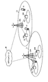
- FIG. 2 is a diagram illustrating an example of carrier aggregation in HetNet.
- the system shown in FIG. 2A is hierarchically configured by a base station eNB (eNodeB) and a plurality of base stations (for example, RRH (Remote Radio Head)).
- a base station eNB eNodeB
- RRH Remote Radio Head
- a small cell small transmission power
- the mobile terminal apparatus UE is located in the small cell of RRH # 1, and communicates with the base station eNB and RRH # 1 by carrier aggregation.
- the carrier aggregation is performed using the component carrier CC # 1 of the base station eNB as the PCell and the component carrier CC # 2 of the base station apparatus RRH # 1 as the SCell.
- RRH is detected by different frequency measurement in a state where the mobile terminal apparatus UE is connected to the base station eNB.
- the mobile terminal apparatus UE is synchronized with PSS / SSS (Primary Synchronization Signal / Secondary Synchronization Signal), which is a synchronization signal, and then the reception quality of different frequencies from each RRH is measured by CRS (Cell-specific Reference Signal). .
- CRS Cell-specific Reference Signal
- a carrier that is not compatible with an existing component carrier may be referred to as an additional carrier type or an extension carrier.
- FIG. 2B shows a state in which the component carrier CC # 1 assigned to the base station eNB and the component carrier CC # 2 assigned to the RRH are both set to the existing carrier type (Legacy carrier type).
- FIG. 2C is a diagram illustrating an example of carrier aggregation using an additional carrier type. CC # 1 assigned to the base station eNB is set to the existing carrier type, and component carrier CC # 2 assigned to the RRH is set to the additional carrier type. 2B and 2C, only CRS, PDCCH, and PDSCH are illustrated for convenience of explanation.
- PDCCH is set to a maximum of 3 symbols from the beginning of one resource block defined by LTE.
- CRS is set so that it does not overlap with other reference signals such as user data and DM-RS (Demodulation-Reference Signal) in one resource block.
- this CRS is used to measure downlink channel quality (CQI) for scheduling and adaptive control, and to measure average channel conditions in downlink for cell search and handover ( Used for mobility measurement).
- the additional carrier type can make PDCCH and CRS untransmitted.
- This additional carrier type is not supported by existing mobile terminal devices (before Rel-10), but is only supported by new mobile terminal devices UE (after Rel-11). Further, the additional carrier type may be no transmission of downlink control channels (PHICH, PCFICH) and no transmission of broadcast information (PBCH, Rel-8 SIB, Paging). Further, it is assumed that the additional carrier type is mainly used in the SCell.
- the CRS when the CRS is not transmitted as the additional carrier type, for example, user-specific DM-RS can be used for data demodulation, and CSI-RS (Channel State Information-Reference Signal) can be used for CSI measurement. .
- CSI-RS Channel State Information-Reference Signal
- an additional carrier type when not transmitting PDCCH, you may transmit FDM type PDCCH.
- the FDM type PDCCH uses a predetermined frequency band of a PDSCH region for downlink data signals as an extended PDCCH region.
- the FDM type PDCCH allocated to this extended PDCCH region is demodulated using DM-RS.
- the extended PDCCH may be referred to as UE-PDCCH.
- Cross-carrier scheduling is a method of transmitting the downlink control channel of the own carrier using another carrier. For example, instead of transmitting the downlink control channel using an additional carrier type carrier, the downlink control channel is transmitted using an existing carrier type carrier.
- the additional carrier type is PHICH (Physical Hybrid-ARQ Indicator Channel) that is not transmitted, retransmission control may be performed using downlink control information (DCI).
- DCI downlink control information
- the additional carrier type may notify the number of OFDM symbols used for the PDCCH by an upper layer signal (Higher layer signaling).
- the additional carrier type may transmit the broadcast information from a carrier of the existing carrier type.
- the additional carrier type may be configured such that at least one of the CRS and the downlink control channel is not transmitted or some signals are reduced.
- the bandwidth of the additional carrier type does not have to be the unit of the system band (base band: 20 MHz) of the LTE system, and can be changed as appropriate.
- interference by CRS is reduced by performing carrier aggregation using an existing carrier type and an additional carrier type. That is, since the CRS can be made non-transmitted in the additional carrier type, the interference of the CRS from the adjacent base station (RRH or the like) can be suppressed, and for example, the downlink signal can be received from the SCell having better reception quality than the PCell. Further, since CRS and PDCCH resources are vacant, the frequency utilization efficiency can be improved by adopting a configuration in which downlink data is transmitted thereto.
- a PUSCH resource is dynamically or periodically secured to an SCell by an upper layer signal, and a PUSCH resource previously secured to the SCell is triggered by downlink scheduling assignment (DL assignment).
- DL assignment downlink scheduling assignment
- a CQI is transmitted together with ACK / NACK using the triggered PUSCH resource in the subframe after the frame.
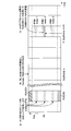
- FIG. 3 illustrates an uplink subframe configuration in which a PUSCH resource is dynamically triggered.
- the mobile terminal apparatus receives a higher layer signal transmitted from the base station and reserves a plurality of PUSCH resources in the SCell for each subframe (FIG. 3 (a)).
- “reserving” a PUSCH resource may be rephrased as “provisionally securing” or “setting” a PUSCH resource.
- provisionally securing or “setting” a PUSCH resource.
- the reserved PUSCH resource is used for data transmission. Can do.
- FIG. 3 shows a state in which three PUSCH resources are reserved per subframe.
- the reserved PUSCH resource is configured in units of physical resource blocks (PRB), and is managed by index numbers (PRBindex1, PRBindex2, PRBindex3).
- the three reserved PUSCH resources (PRBindex1, PRBindex2, PRBindex3) may be shared by a plurality of mobile terminal apparatuses. Since the base station knows the PUSCH resource reserved in the mobile terminal apparatus, when triggering the reserved PUSCH resource for a plurality of mobile terminal apparatuses in the same subframe, the base station is selected from the plurality of reserved PUSCH resources. Trigger reserved PUSCH resources that differ between terminals.
- the base station (for example, SCell) transmits the downlink scheduling assignment on the PDCCH or E-PDCCH in the subframe in which the PDSCH is transmitted to the mobile terminal apparatus.
- the base station sets an index number corresponding to a reserved PUSCH resource for UCI transmission in downlink scheduling assignment.
- the base station transmits a downlink scheduling assignment in which an index number corresponding to the reserved PUSCH resource is set to the mobile terminal apparatus using PDCCH or E-PDCCH. Any reserved PUSCH resource is triggered by the downlink scheduling assignment trigger bit and assigned to the uplink of the SCell.
- the CQI report is an example of a channel quality report and is not limited to the CQI report.
- PUSCH resources may be triggered dynamically or periodically by downlink scheduling assignment.
- ACK / NACK and CSI report are transmitted using the same PUSCH resource.
- CSI and ACK / NACK may be transmitted in the same subframe using PUSCH triggered by downlink scheduling assignment.
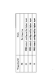
- FIG. 4 is a specific example of trigger bits set for downlink scheduling assignment.
- the trigger bit “11” designates an index.
- UCI is transmitted using PUSCH resources dynamically allocated in this way. If the number of trigger bits is 3 bits or more, 4 or more PUSCH resources can be dynamically selected for each subframe.
- the mobile terminal apparatus triggers one of the reserved PUSCH resources used for UCI transmission by the trigger bit set in the downlink scheduling assignment received from the base station (for example, SCell) (FIG. 3 (b)). For example, the mobile terminal apparatus demodulates the PDSCH based on the downlink scheduling assignment included in the subframe received by the SCell, generates ACK / NACK for the PDSCH, and generates CQI indicating the reception quality of the downlink channel in the subframe. taking measurement.
- the base station for example, SCell
- the mobile terminal apparatus demodulates the PDSCH based on the downlink scheduling assignment included in the subframe received by the SCell, generates ACK / NACK for the PDSCH, and generates CQI indicating the reception quality of the downlink channel in the subframe. taking measurement.
- the mobile terminal apparatus receives a subframe (for example, the (n + 4) th subframe after 4 subframes) after a predetermined subframe from the subframe (for example, the nth subframe) in which the downlink scheduling allocation that triggers the dynamic PUSCH resource is detected.
- a subframe for example, the (n + 4) th subframe after 4 subframes
- ACK / NACK and CQI are transmitted to the base station (for example, RRH) that transmitted the downlink scheduling assignment (FIG. 3 (c)).
- the figure shows a state where the PUSCH resource corresponding to PRBindex2 is dynamically selected by the trigger bit “10”.
- the PUSCH resource used for UCI transmission is dynamically triggered by downlink scheduling assignment, it can be used even when there is no uplink data traffic. Since the CQI is used for downlink scheduling in the base station, it is sufficient to be able to trigger the PUSCH resource used for UCI transmission where there is downlink data (PDSCH). Since there is always a PDSCH demodulated by downlink scheduling assignment, the CQI can be transmitted together with the ACK / NACK for that PDSCH using the dynamically triggered PUSCH resource. Although the PUSCH can be triggered by using the uplink scheduling grant, if there is no uplink data traffic, the uplink scheduling grant must be transmitted only for UCI transmission.
- PDSCH downlink data
- the restriction on subframes used for UCI transmission can be relaxed.
- the PUSCH resource used for UCI transmission is only temporarily reserved, the PUSCH resource that does not transmit UCI among the provisionally reserved PUSCH resources can be used for uplink data transmission.
- FIG. 5 illustrates an uplink subframe configuration in which PUSCH resources are periodically triggered.
- PUSCH resources are reserved periodically (for example, every 10 subframes). If UCI transmission occurs, one of the periodically reserved PUSCH resources is triggered, and UCI transmission is performed using the triggered PUSCH resource.
- the mobile terminal apparatus periodically reserves a plurality of PUSCH resources at intervals of a plurality of subframes by an upper layer signal transmitted from a base station (for example, SCell) (FIG. 5 (a)).
- FIG. 5 shows a state in which three PUSCH resources are periodically reserved for one uplink subframe.
- the periodic PUSCH resource (PRBindex1, PRBindex2, PRBindex3) may be shared by a plurality of mobile terminal apparatuses. Since the base station knows periodically reserved PUSCH resources, when triggering periodic PUSCH resources for a plurality of mobile terminal apparatuses in the same subframe, different periodic PUSCH resources between terminals are used. Specify multiple mobile terminals.
- the base station (for example, SCell) transmits the downlink scheduling assignment on the PDCCH or E-PDCCH in the subframe in which the PDSCH is transmitted to the mobile terminal apparatus.
- this downlink scheduling assignment an index number corresponding to the periodic PUSCH resource, a subframe number that triggers the periodic PUSCH resource, and a repetition period in the time direction of the periodic PUSCH resource are set.
- the base station transmits a downlink scheduling assignment in which an index number, a subframe number, and a repetition period corresponding to the periodic PUSCH resource are set to the mobile terminal apparatus using PDCCH or E-PDCCH. Either the subframe number or the repetition period may be notified.
- the periodic PUSCH resource used for UCI transmission is triggered by the trigger bit set in the downlink scheduling assignment (FIG. 5 (b)).
- the mobile terminal apparatus demodulates the PDSCH based on a downlink scheduling assignment included in a subframe with an SCell, generates an ACK / NACK for the PDSCH, and measures a CQI indicating the reception quality of the downlink channel in the subframe. To do.
- the mobile terminal apparatus reserves periodic PUSCH resources based on the index number, subframe number, and repetition period included in the downlink scheduling assignment (for example, every 10 subframes).
- the mobile terminal apparatus / NACK and CQI are transmitted to the base station (for example, RRH) that transmitted the downlink scheduling assignment using the periodic PUSCH resource (FIG. 5 (c)).
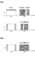
- FIG. 6A shows a PCell to which an existing carrier type (Rel-8) is applied and an SCell to which an additional carrier type is applied.
- the additional carrier type is applied to the SCell
- the E-PDCCH and the PDSCH demodulated based on the E-PDCCH are transmitted from the RRH.
- the RRH triggers a dynamic or periodic PUSCH resource for transmitting CQI to the mobile terminal apparatus
- the mobile terminal apparatus receives the SCell downlink signal, demodulates the E-PDCCH included in the downlink signal, and detects downlink scheduling assignment.
- the PDSCH is demodulated based on the downlink scheduling assignment, and ACK / NACK for the PDSCH is generated. If CQI reporting is triggered by downlink scheduling assignment, the CQI of the downlink signal in the additional carrier type is measured in a predetermined frequency unit. At this time, if the trigger bit is set in the downlink scheduling assignment, the dynamic or periodic PUSCH resource of the PRB index specified by the trigger bit is triggered. CQI and ACK / NACK are transmitted using dynamic or periodic PUSCH resources triggered on the uplink of SCell.
- a trigger bit indicating the index number of the dynamic or periodic PUSCH resource is set in the downlink scheduling allocation included in the PDCCH.
- the mobile terminal apparatus receives the SCell downlink signal, demodulates the PDCCH, and triggers the dynamic or periodic PUSCH resource of the PRB index specified by the trigger bit if the trigger bit is set in the downlink scheduling assignment. (Assignment of PUSCH resource corresponding to PRBindex).
- the dynamic or periodic PUSCH resource may be set only in one of SCell and PCell, or may be set in both SCell and PCell.
- PCell is mainly responsible for ensuring coverage
- SCell is expected to realize a high transmission rate in a local area where traffic is high. Therefore, an increase in UCI information such as ACK / NACK is expected in a situation where SCell is added. For this reason, in a situation where an SCell is added in HetNet, it is desirable to set a dynamic or periodic PUSCH resource for the SCell from the viewpoint of suppressing the CQI drop frequency.
- the CQI drop frequency can be set by setting the dynamic or periodic PUSCH resource to PCel as in the existing PUCCH. Can be suppressed.
- signal resource information of the dynamic or periodic PUSCH resource to be reserved together with an upper layer signal requesting the mobile terminal apparatus to add the SCell It is possible. If the communication by PCell is established between the base station and the mobile terminal device in advance, and the quality of the SCell reported from the mobile terminal device exceeds the threshold, the SCell is sent to the mobile terminal device by the higher layer signal. Add At this time, the resource information (PRB index, subframe number, or any or all of the period) of the dynamic or periodic PUSCH resource is included in the upper layer signal that requests the mobile terminal apparatus to add the SCell.
- independent resources for example, different PRB indexes
- SCell and PCell when the system bandwidth is the same (for example, PCell and The number of RBs of the SCell is the same (for example, 50 RBs each), and a common resource (for example, PRB # 0-49 for both PCell and SCell) may be used.
- the mobile terminal apparatus secures dynamic or periodic PUSCH resources in the uplink of PCell and SCell, and dynamic or periodic PUSCH resources triggered by PCell such as ACK / NACK and CQI for PDSCH received by PCell Or it transmits using PUCCH resource and transmits UCI, such as ACK / NACK and CQI with respect to PDSCH received by SCell, using the dynamic or periodic PUSCH resource triggered by SCell.
- the dynamic or periodic PUSCH resource can be used as a resource for transmitting only ACK / NACK in the uplink.
- a downlink scheduling assignment that triggers a dynamic or periodic PUSCH resource is transmitted to the mobile terminal apparatus by PDCCH or E-PDCCH of SCell.
- the mobile terminal apparatus can transmit ACK / NACK using the dynamic or periodic PUSCH resource triggered by the SCell.
- PCell PUCCH or SCell PUCCH may be used as a resource for transmitting only ACK / NACK in the uplink (FIG. 6B).
- the PDSCH is transmitted only from the downlink of the SCell, if the PUCCH is defined in the SCell, it may be used, and if it is not defined, the PCell may be used.
- CQI CQI is not triggered, it is necessary to specify in the specification whether transmission is performed using PUCCH or transmission using ACK / NACK using dynamic or periodic PUSCH resources.
- the PUCCH (format 1a / 1b) is transmitted from the uplink of the PCell.
- ACK / NACK is transmitted using PUCCH (format 1a / 1b) of PCell.
- the PUCCH (format 1a / 1b) is transmitted from the uplink of the SCell.
- ACK / NACK is transmitted using PUCCH (format 1a / 1b) of SCell.
- UCI is transmitted from either uplink PCell or uplink SCell using the carrier aggregation PUCCH format. Which cell is used is notified to the mobile terminal apparatus by an upper layer signal.
- the dynamic or periodic PUSCH of the SCell is preferentially used. And transmit UCI of PCell and SCell. This is because the PUSCH resource can transmit more bit data than the PUCCH resource. It is specified beforehand that the dynamic or periodic PUSCH of the SCell has priority according to the specification. In Rel-10, the cell number of PCell is “0”, and the cell number of SCell is “1”, “2”.
- ACK / NACK is transmitted using the PUSCH triggered by the uplink scheduling grant.
- UCI (ACK / NACK + CQI) is transmitted using the PUSCH triggered according to the uplink scheduling grant.
- the PUSCH When the PUSCH is assigned by the uplink scheduling grant, the PUSCH is transmitted by the PRB having a good channel quality based on the scheduling, so it is desirable to transmit by the PUSCH.
- the CQI report when the CQI report is not triggered by the uplink scheduling grant, but is triggered by the downlink scheduling assignment, it is treated as an erroneous setting. In addition, when the CQI report is triggered by both the uplink scheduling grant and the downlink scheduling assignment, it is also treated as an erroneous setting.
- FIG. 8 is an explanatory diagram of the system configuration of the wireless communication system according to the present embodiment.
- the radio communication system shown in FIG. 8 is a system including, for example, an LTE system or a successor system, and supports the above-described functions.
- carrier aggregation in which a plurality of basic frequency blocks having the system band of the LTE system as one unit is integrated is used.
- this wireless communication system may be called IMT-Advanced or 4G.
- the wireless communication system is HetNet, and a base station device (first base station device) 20A in cell C1 and a plurality of base station devices (first devices in cell C2 provided in cell C1).
- 2 base station apparatus) 20B a hierarchical network is constructed.
- the base station device 20A is a so-called macro base station device and covers a large cell C1.
- the base station apparatus 20B is a so-called RRH base station apparatus, and a small cell C2 is locally formed in the cell C1.
- the base station device 20A and each base station device 20B are connected to each other by wired connection or wireless connection.
- the mobile terminal apparatus 10 can communicate with the base station apparatuses 20A and 20B in the cells C1 and C2, respectively.
- the base station device 20A is connected to the core network 30 via a higher station device.
- the upper station device includes, but is not limited to, an access gateway device, a radio network controller (RNC), a mobility management entity (MME), and the like.
- Each mobile terminal device 10 includes an existing mobile terminal device (before Rel-10) and a new mobile terminal device (after Rel-11), but in the following, mainly a new mobile terminal device (after Rel-11) ).
- RNC radio network controller
- MME mobility management entity
- Each mobile terminal device 10 includes an existing mobile terminal device (before Rel-10) and a new mobile terminal device (after Rel-11), but in the following, mainly a new mobile terminal device (after Rel-11) ).
- each mobile terminal device 10 performs radio communication with the base station devices 20A and 20B.
- user devices UE: UE including both mobile terminal devices and fixed terminal devices. User Equipment).
- This wireless communication system supports carrier aggregation suitable for HetNet.
- the mobile terminal apparatus 10 receives a downlink signal from each base station apparatus 20B while being connected to the base station apparatus 20A (PCell).
- the mobile terminal apparatus 10 measures the signal quality from each base station apparatus 20B based on the downlink signal, and feeds back the measurement result to the base station apparatus 20A.
- the base station device 20A detects the base station device 20B having good reception quality as an SCell, and performs carrier aggregation.
- OFDMA Orthogonal Frequency Division Multiple Access
- SC-FDMA Single Carrier Frequency Division Multiple Access
- OFDMA is a multi-carrier transmission scheme that performs communication by dividing a frequency band into a plurality of narrow frequency bands (subcarriers) and mapping data to each subcarrier.
- SC-FDMA is a single carrier transmission method that reduces interference between terminals by dividing a system band into bands each consisting of one or continuous resource blocks for each terminal, and a plurality of terminals using different bands. .
- the downlink communication channel includes PDSCH shared by each mobile terminal apparatus 10 and downlink L1 / L2 control channels (PDCCH, PCFICH, PHICH). User data and higher control information are transmitted by the PDSCH. PDSCH and PUSCH scheduling information and the like are transmitted by the PDCCH.
- the number of OFDM symbols used for PDCCH is transmitted by PCFICH (Physical Control Format Indicator Channel).
- the HARQ ACK / NACK for PUSCH is transmitted by PHICH (Physical Hybrid-ARQ Indicator Channel).
- the uplink communication channel has PUSCH as an uplink data channel shared by each mobile terminal apparatus and PUCC which is an uplink control channel. User data and higher control information are transmitted by this PUSCH. Also, downlink CQI, ACK / NACK, and the like are transmitted by PUCCH.
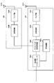
- base station apparatuses 20A and 20B the overall configuration of base station apparatuses 20A and 20B according to the present embodiment will be described. Note that baseband processing is not performed in the base station apparatus 20B, and the base station apparatus 20B receives the baseband signal from the base station apparatus 20A and notifies the mobile terminal apparatus 10 thereof.
- the base station apparatus 20A includes a transmission / reception antenna 201A, an amplifier unit 202A, a transmission / reception unit 203A, a baseband signal processing unit 204A, a call processing unit 205A, and a transmission path interface 206A.
- the base station device 20B includes a transmission / reception antenna 201B, an amplifier unit 202B, and a transmission / reception unit 203B. Transmission data transmitted from the base station apparatuses 20A and 20B to the mobile terminal apparatus 10 via the downlink is input from the higher station apparatus to the baseband signal processing unit 204A via the transmission path interface 206A.
- the downlink data channel signal is transmitted from the RCP layer, such as PDCP layer processing, user data division / combination, RLC (Radio Link Control) retransmission control transmission processing, and MAC (Medium Access).
- RCP layer such as PDCP layer processing, user data division / combination, RLC (Radio Link Control) retransmission control transmission processing, and MAC (Medium Access).
- Control Retransmission control, for example, HARQ transmission processing, scheduling, transmission format selection, channel coding, inverse fast Fourier transform (IFFT) processing, and precoding processing are performed. Also, transmission processing such as channel coding and inverse fast Fourier transform is performed on the downlink control channel signal.
- the baseband signal processing unit 204A notifies the mobile terminal device 10 connected to the same cell of the control information for each mobile terminal device 10 to perform wireless communication with the base station devices 20A and 20B through the broadcast channel.
- the information for communication in the cell includes, for example, system bandwidth in uplink or downlink, and root sequence identification information (Root Sequence) for generating a random access preamble signal in PRACH (Physical Random Access Channel). Index) etc. are included.
- a baseband signal corresponding to the PCell component carrier CC # 1 is output from the baseband signal processing unit 204A to the transmission / reception unit 203A, and from the baseband signal processing unit 204A to the transmission / reception unit 203B of the base station apparatus 20B.
- a baseband signal corresponding to the SCell component carrier CC # 2 is output through the optical fiber.
- the transmission / reception units 203A and 203B convert the baseband signal output from the baseband signal processing unit 204A to a radio frequency band.
- the amplifier units 202A and 202B amplify the frequency-converted radio frequency signal and transmit the amplified signal using the transmission / reception antennas 201A and 201B.
- radio frequency signals received by the transmission / reception antennas 201A and 201B of the base station apparatuses 20A and 20B are amplified by the amplifier sections 202A and 202B.
- the frequency is converted by the transmission / reception units 203A and 203B, converted into a baseband signal, and input to the baseband signal processing unit 204A.
- the baseband signal processing unit 204A performs FFT processing, IDFT processing, error correction decoding, MAC retransmission control reception processing, RLC layer, and PDCP layer reception processing on transmission data included in the input baseband signal. Made.
- the baseband signal is transferred to the upper station apparatus via the transmission path interface 206A.
- the call processing unit 205A performs call processing such as communication channel setting and release, state management of the base station apparatuses 20A and 20B, and management of radio resources.
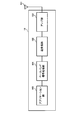
- the mobile terminal apparatus 10 includes a transmission / reception antenna 101, an amplifier unit 102, a transmission / reception unit 103 (reception unit), a baseband signal processing unit 104, and an application unit 105.
- a radio frequency signal received by the transmission / reception antenna 101 is amplified by the amplifier unit 102, frequency-converted by the transmission / reception unit 103, and converted into a baseband signal.
- the baseband signal is subjected to FFT processing, error correction decoding, retransmission control reception processing, and the like by the baseband signal processing unit 104.
- downlink user data is transferred to the application unit 105.
- the application unit 105 performs processing related to layers higher than the physical layer and the MAC layer. Also, broadcast information in the downlink data is also transferred to the application unit 105.
- uplink transmission data is input from the application unit 105 to the baseband signal processing unit 104.
- the baseband signal processing unit 104 performs mapping processing, retransmission control (H-ARQ) transmission processing, channel coding, DFT processing, and IFFT processing.
- the transmission / reception unit 103 converts the baseband signal output from the baseband signal processing unit 104 into a radio frequency band. Thereafter, the signal is amplified by the amplifier unit 102 and transmitted from the transmission / reception antenna 101.
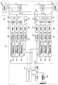
- FIG. 11 is a functional block diagram of a baseband signal processing unit 204A and some upper layers included in the base station apparatus 20A according to the present embodiment, and mainly includes functional blocks of transmission processing of the baseband signal processing unit 204A. Show. Transmission data for the mobile terminal apparatus 10 under the control of the base station apparatus 20A is transferred from the higher station apparatus to the base station apparatus 20A.
- the base station device 20A is illustrated.
- the base station device 20A shows a configuration that can support carrier aggregation of two component carriers CC # 1 and CC # 2.
- the number of CCs used by each base station apparatus 20 is not limited to this.
- the control information generation unit 300 generates upper control information to be notified to the mobile terminal apparatus 10 by upper layer signaling for each user.
- the upper control information includes resource information for reserving dynamic or periodic PUSCH in the uplink of component carriers CC # 1 and CC # 2 (for example, when reserving periodic PUSCH, PRBindex, subframe number, Period).
- the data generation unit 301 outputs the transmission data transferred from the higher station apparatus as user data for each user.
- the component carrier selection unit 302 selects a component carrier used for wireless communication with the mobile terminal device 10 for each mobile terminal device 10.
- the component carrier CC # 1 of the base station device 20A is set to PCell, and the SCell is selected from the other base station device 20B via the optical fiber 319.
- the base station apparatus 20A notifies the mobile terminal apparatus 10 of addition / reduction of component carriers by higher layer signaling, and receives an application completion message from the mobile terminal apparatus 10.
- the scheduling unit 310 controls the allocation of component carriers to the subordinate mobile terminal devices 10 according to the communication quality of the entire system band.
- the scheduling unit 310 performs scheduling while distinguishing between LTE terminal users and LTE-A terminal users.
- Scheduling section 310 receives data to be transmitted from the upper station apparatus and a retransmission instruction, and receives a channel estimation value and a CQI of a resource block from a receiving section that measures an uplink signal.
- the scheduling unit 310 performs scheduling of the downlink control channel signal and the downlink shared channel signal while referring to the input retransmission instruction, channel estimation value, and CQI.
- the propagation path in wireless communication varies depending on the frequency due to frequency selective fading. Therefore, scheduling section 310 instructs a resource block (mapping position) with good communication quality for each subframe for downlink data to each mobile terminal apparatus 10 (referred to as adaptive frequency scheduling).
- adaptive frequency scheduling the mobile terminal apparatus 10 with good channel quality is selected for each resource block. Therefore, the scheduling unit 310 indicates a resource block (mapping position) using the CQI for each resource block fed back from the mobile terminal apparatus 10.
- the scheduling unit 310 instructs a resource block with good communication quality for each subframe with respect to control information transmitted on the PDCCH (or E-PDCCH) by adaptive frequency scheduling. For this reason, the scheduling unit 310 indicates a resource block (mapping position) using the CQI for each resource block fed back from each mobile terminal apparatus 10. Also, an MCS (coding rate, modulation scheme) that satisfies a predetermined block error rate with the allocated resource block is determined. Parameters satisfying the MCS (coding rate, modulation scheme) determined by the scheduling unit 310 are set in the channel coding units 303 and 308 and the modulation units 304 and 309. The applied frequency scheduling is performed not only for the base station apparatus 20A but also for the base station apparatus 20B via the optical fiber 319.
- MCS coding rate, modulation scheme
- the baseband signal processing unit 204A includes a channel encoding unit 303, a modulation unit 304, and a mapping unit 305 corresponding to the maximum user multiplexing number N within one component carrier.
- the channel coding unit 303 channel-codes the downlink shared data channel (PDSCH) configured by the downlink data (including some higher control signals) output from the data generation unit 301 for each user.
- the modulation unit 304 modulates channel-coded user data for each user.
- the mapping unit 305 maps the modulated user data to radio resources.
- the baseband signal processing unit 204A includes a downlink control information generation unit 306 that generates downlink control information, a channel encoding unit 308, and a modulation unit 309.
- the uplink shared data channel control information generator 306b generates an uplink scheduling grant (UL Grant) for controlling the uplink data channel (PUSCH).
- the uplink scheduling grant is generated for each user.
- the downlink shared data channel control information generation unit 306c generates a downlink scheduling assignment (DL assignment) for controlling the downlink data channel (PDSCH).
- the downlink scheduling assignment is generated for each user.
- the baseband signal processing unit 204A (CC # 2) addressed to the base station apparatus 20B sets a trigger bit based on FIG. 4 for downlink scheduling assignment.
- a trigger bit is set for downlink scheduling assignment at the timing of triggering the CQI report to the mobile terminal apparatus 10. For example, as shown in FIG. 3, when UCI transmission is performed using a PUSCH resource corresponding to PRBindex2, “10” is set as a trigger bit.
- a trigger bit is set for downlink scheduling assignment based on FIG.
- a trigger bit is set for downlink scheduling assignment at the timing of triggering the CQI report to the mobile terminal apparatus 10. For example, as shown in FIG. 3, when UCI transmission is performed using a PUSCH resource corresponding to PRBindex2, “10” is set as a trigger bit. When dynamic or periodic PUSCH used for CIU transmission is not triggered, “00” is set as a trigger bit. Also, the common channel control information generation unit 306a generates common control channel control information that is downlink control information common to users.
- the control information modulated for each user by the modulation unit 309 is multiplexed by the control channel multiplexing unit 314 and further interleaved by the interleaving unit 315.
- the control signal output from the interleaving unit 315 and the user data output from the mapping unit 305 are input to the IFFT unit 316 as downlink channel signals.
- the IFFT unit 316 receives the control signal from the interleaving unit 315 and the user data from the mapping unit 305 as downlink channel signals. Further, the IFFT unit 316 further receives a downlink reference signal. For the downlink reference signal, CRS for channel estimation, DM-RS for downlink demodulation, and CSI-RS for CSI measurement may be generated. The IFFT unit 316 performs inverse fast Fourier transform on the downlink channel signal and downlink reference signal to convert the frequency domain signal into a time-series signal. The cyclic prefix insertion unit 317 inserts a cyclic prefix into the time-series signal of the downlink channel signal. The cyclic prefix functions as a guard interval for absorbing a difference in multipath propagation delay. The transmission data to which the cyclic prefix is added is sent to the transmission / reception units 203A and 203B.
- all subframes may be set as an additional carrier type, a predetermined subframe may be set as an additional carrier type, and the remaining subframes may be set as an existing carrier type.
- a new mobile terminal device Rel-11 or later
- an existing mobile terminal device before Rel-10 is connected to the component carrier CC # 2 assigned to the base station device 20B during the period of the existing carrier type. Can be made.
- FIG. 12 is a functional block diagram of the baseband signal processing unit 104 of the mobile terminal apparatus 10, and shows functional blocks of an LTE-A terminal that supports an additional carrier type.
- the CP removal section 401 removes the CP from the downlink signal received as received data from the base station apparatuses 20A and 20B.
- the downlink signal from which the CP is removed is input to the FFT unit 402.
- the FFT unit 402 performs fast Fourier transform (FFT) on the downlink signal, converts the signal from the time domain to the signal in the frequency domain, and inputs the signal to the demapping unit 403.
- the demapping unit 403 demaps the downlink signal, and extracts multiplex control information, user data, and higher control signal in which a plurality of control information is multiplexed from the downlink signal. Note that the demapping process by the demapping unit 403 is performed based on a higher control signal input from the application unit 105.
- the multiplex control information output from the demapping unit 403 is deinterleaved by the deinterleaving unit 404.
- the baseband signal processing unit 104 also includes a downlink control information demodulation unit 405 that demodulates downlink control information, a data demodulation unit 406 that demodulates downlink shared data, a channel estimation unit 407, a reception quality measurement unit (measurement unit) 408, an allocation Part 409.
- the allocation unit 409 may be configured not to be included in the baseband signal processing unit 104 as will be described later.
- the downlink control information demodulation section 405 demodulates the common channel control information demodulation section 405a that demodulates the common control channel control information from the multiplexed control information, and the uplink shared data channel control information from the multiplexed control information.
- an uplink shared data channel control information demodulator 405b, and a downlink shared data channel control information demodulator 405c that demodulates the downlink shared data channel control information from the multiplexed control information.
- the common channel control information demodulator 405a extracts common control channel control information, which is common control information for users, through blind decoding processing, demodulation processing, channel decoding processing, and the like of the common search space of the downlink control channel (PDCCH). .
- the common control channel control information includes downlink channel quality information (CQI), is input to the mapping unit 415, and is mapped as part of transmission data to the base station apparatus 20.
- CQI downlink channel quality information
- the uplink shared data channel control information demodulator 405b performs uplink shared data channel control information (for example, UL Grant) through blind decoding processing, demodulation processing, channel decoding processing, etc. of the user-specific search space of the downlink control channel (PDCCH). ).
- the demodulated uplink shared data channel control information is input to the mapping unit 415 and used for uplink shared data channel (PUSCH) control.
- the downlink shared data channel control information demodulating section 405c performs user-specific downlink shared data channel control information (for example, blind decoding processing, demodulation processing, channel decoding processing, etc.) for the user dedicated search space of the downlink control channel (PDCCH). , Downlink scheduling allocation).
- the PUSCH trigger bit is set for downlink scheduling assignment.
- the demodulated downlink shared data channel control information is input to the data demodulating unit 406 and used for controlling the downlink shared data channel (PDSCH).
- the data demodulator 406 includes a downlink shared data demodulator 406a that demodulates user data and higher control signals, and a downlink common channel data demodulator 406b that demodulates downlink common channel data.
- the downlink shared data demodulator 406a acquires user data and higher control information based on the downlink shared data channel control information input from the downlink shared data channel control information demodulator 405c.
- An SCell of an additional carrier type is added by a request to add an SCell included in the higher control information.
- the upper control information includes the resource information of the dynamic or periodic PUSCH resource
- the dynamic or periodic PUSCH resource is reserved according to the resource information. In the example shown in FIG. 4, PUSCH resources of PRB indexes 1, 2, and 3 are reserved.
- the downlink common channel data demodulation unit 406b demodulates the downlink common channel data based on the uplink shared data channel control information input from the uplink shared data channel control information demodulation unit 405b.
- the data demodulation unit 406 performs derate matching by switching the rate matching pattern according to the carrier type of the component carrier. For example, in an additional carrier type component carrier, demodulation processing is appropriately performed in consideration of user data allocated to CRS and PDCCH resources.
- the channel estimation unit 407 performs channel estimation using a user-specific reference signal (DM-RS) or a cell-specific reference signal (CRS).
- DM-RS user-specific reference signal
- CRS cell-specific reference signal
- the channel estimation unit 407 determines the estimated channel variation from the common control channel control information demodulation unit 405a, the uplink shared data channel control information demodulation unit 405b, the downlink shared data channel control information demodulation unit 405c, and the downlink shared data demodulation unit 406a. Output to.
- These demodulation units perform demodulation processing using the estimated channel fluctuation and demodulation reference signal.
- the reception quality measurement unit 408 measures CQI that is an indicator indicating the reception quality of the downlink channel.
- Reception quality measuring section 408 outputs the reception quality measurement result to mapping section 415 and feeds back to base station apparatus 20A.
- the measurement result of the reception quality may be directly fed back from the mobile terminal apparatus 10 to the base station apparatus 20A, or may be fed back from the mobile terminal apparatus 10 to the base station apparatus 20A via the base station apparatus 20B.
- the allocation unit 409 determines PUSCH resources to be reserved in the SCell based on the upper layer signal demodulated by the downlink shared data demodulation unit 406a.
- a plurality of PUSCH resources can be reserved for each subframe by an upper layer signal (see FIG. 3). Also, depending on the upper layer signal, a plurality of PUSCH resources can be reserved at a plurality of subframe intervals (see FIG. 5).
- the allocation unit 409 is designated from the reserved PUSCH resources based on the trigger bits (see FIG. 4) included in the downlink scheduling allocation demodulated by the downlink shared data channel control information demodulation unit 405c. Trigger PUSCH resource.
- the PUSCH resource specified by the trigger bit included in the downlink scheduling assignment is assigned to the SCell, for example.
- ACK / NACK and CQI report are transmitted together to the base station (RRH) using the PUSCH resource triggered in the uplink of the SCell.
- the allocation unit 409 handles PUSCH with uplink scheduling grant and PDSCH with downlink scheduling allocation as follows.
- ACK / NACK is transmitted using the PUSCH triggered by the uplink scheduling grant.
- the USCH (ACK / NACK + CQI) is transmitted using the PUSCH triggered according to the uplink scheduling grant.
- the uplink scheduling grant does not trigger CQI reporting, but it is misconfigured when triggered by downlink scheduling assignment, and when both uplink scheduling grant and downlink scheduling assignment trigger CQI reporting. Treat as.
- the assigning unit 409 ACKs the PDSCH assigned by the downlink scheduling assignment. / NACK can be transmitted from the SCell using any of the reserved PUSCH resources.
- the allocation unit 409 uses the PUSCH or the PUCCH assigned to the uplink of the PCell for the ACK / NACK and / or CQI report for the PDSCH received by the PCell. To transmit in a predetermined subframe. Moreover, you may transmit the ACK / NACK with respect to PDSCH received by SCell, and a CQI report by the same sub-frame as PCell using PUSCH allocated to the uplink of SCell.
- the allocation unit 409 transmits the ACK / NACK and the CQI report by the PDSCH allocated to the uplink of the SCell by the PUSCH allocated to the uplink of the PCell. It is desirable to prioritize UCI transmission.
- the allocating unit 409 has two types of UCI transmission by the PUSCH allocated to the uplink of the PCell and UCI transmission by the PUSCH allocated to the uplink of the SCell.
- the carrier having the smallest cell number among the two carriers is given priority.
- the allocation part 409 may notify the priority of SCell when the transmission time of the uplink control information by PCell and SCell overlaps with an upper layer signal in advance.
- the baseband signal processing unit 104 includes a data generation unit 411, a channel encoding unit 412, a modulation unit 413, a DFT unit 414, a mapping unit 415, an IFFT unit 416, and a CP insertion unit 417 as functional blocks of the transmission processing system. I have.
- the data generation unit 411 generates transmission data from the bit data input from the application unit 105.
- the channel coding unit 412 performs channel coding processing such as error correction on the transmission data, and the modulation unit 413 modulates the channel-coded transmission data with QPSK or the like.
- the DFT unit 414 performs discrete Fourier transform on the modulated transmission data.
- Mapping section 415 maps each frequency component of the data symbol after DFT to a subcarrier position designated by base station apparatuses 20A and 20B.
- the IFFT unit 416 performs inverse fast Fourier transform on input data corresponding to the system band to convert it into time series data, and the CP insertion unit 417 inserts a cyclic prefix into the time series data at data delimiters.
- a PUSCH resource is reserved for each uplink subframe of the SCell or at a predetermined cycle by an upper layer signal, and an arbitrary reserved PUSCH resource is set by a trigger bit included in the downlink scheduling assignment.
- a CQI report can be transmitted together with ACK / NACK using the PUSCH resource.
- an arbitrary reserved PUSCH resource can be triggered by downlink scheduling allocation and resource allocation to the uplink can be performed. Therefore, the frequency of CQI dropping at the time of carrier aggregation in HetNet is reduced. It is possible to construct a system that can suppress and transmit UCI with high efficiency.
- the present invention is not limited to the above embodiment, and can be implemented with various modifications.
- the number of carriers, the carrier bandwidth, the signaling method, the type of additional carrier type, the number of processing units, and the processing procedure in the above description can be changed as appropriate. It is. Other modifications can be made without departing from the scope of the present invention.
Landscapes
- Engineering & Computer Science (AREA)
- Signal Processing (AREA)
- Computer Networks & Wireless Communication (AREA)
- Quality & Reliability (AREA)
- Mobile Radio Communication Systems (AREA)
Abstract
HetNetにおけるキャリアアグリゲーションの際に、SCellに動的又は周期的にPUSCHをトリガして、UCIを効率的に送信すること。本発明の通信システムでは、移動端末装置が、上位レイヤ信号によって第2のキャリアに物理上りリンク共有チャネル用リソースを予約し、下りリンクスケジューリング割当てによって割り当てられた物理下りリンク共有データチャネルに対するACK/NACKと、当該下りリンクスケジューリング割当てによってトリガされたCQI報告とを組み合わせた上りリンク制御情報を、予約された物理上りリンク共有チャネル用リソースのいずれかを用いて第2の基地局装置へ送信する。
Description
本発明は、次世代移動通信システムにおける基地局装置、移動端末装置、通信システム及び通信方法に関する。
UMTS(Universal Mobile Telecommunications System)ネットワークにおいて、さらなる高速データレート、低遅延などを目的としてロングタームエボリューション(LTE:Long Term Evolution)が検討されている(非特許文献1)。LTEではマルチアクセス方式として、下り回線(下りリンク)にOFDMA(Orthogonal Frequency Division Multiple Access)をベースとした方式を用い、上り回線(上りリンク)にSC-FDMA(Single Carrier Frequency Division Multiple Access)をベースとした方式を用いている。
LTEシステムにおいて、上りリンク信号は適切な無線リソースにマッピングされて移動端末装置から無線基地局装置に送信される。具体的には、上りユーザデータは、上りリンク共有チャネル(PUSCH:Physical Uplink Shared Channel)を用いて送信される。また、上りリンク制御情報(UCI:Uplink Control Information)は、上りユーザデータと共に送信する場合はPUSCHを用いて、単独で送信する場合は上りリンク制御チャネル(PUCCH:Physical Uplink Control Channel)を用いて送信される。
上りリンク制御情報(UCI)には、下りリンク共有チャネル(PDSCH:Physical Downlink Shared Channel)に対する送達確認(ACK/NACK)、スケジューリング要求、チャネル状態情報(CSI:Channel State Information)等が含まれる(例えば、非特許文献2)。チャネル状態情報(以下、CSIという)は、下りリンクの瞬時のチャネル状態に基づく情報であり、例えば、チャネル品質情報(CQI:Channel Quality Indicator)、プリコーディングマトリックス指標(PMI)、ランク指標(RI)などである。このCSIは、周期的又は非周期的に、移動端末装置から無線基地局装置に通知される。
一方、LTEからのさらなる広帯域化及び高速化を目的として、LTEの後継システムが検討されている(例えば、LTEアドバンスト又はLTEエンハンスメントと呼ぶこともある(以下、「LTE-A」という)。LTE-A(Rel-10)においては、LTEシステムのシステム帯域を1単位とする複数のコンポーネントキャリア(CC: Component Carrier)を束ねて広帯域化することにより高いピークデータレートを実現する(キャリアアグリゲーション)。また、従来のマクロ基地局に加え、ピコ基地局、フェムト基地局、RRH(Remote Radio Head)基地局などの送信電力の異なる様々な形態の基地局を配置するオーバレイ型ネットワーク(HetNet:Heterogeneous Network)構成が検討されている。3GPPにおいて、HetNetにおける干渉コーディネーション技術として、時間領域の干渉コーディネーション(eICIC: enhanced Inter-Cell Interference Coordination)の仕様化が行われ、システム容量のさらなる増大が図られた。
3GPP, TR 25.913"Requirements for Evolved UTRA and Evolved UTRAN"
3GPP, TS36.212(V.9.3.0), "Multiplexing and channel coding", Nov.2010
ところで、将来のシステム(Rel-11以降)では、周波数利用効率の向上や、HetNetにおける与干渉の低減を考慮したキャリアアグリゲーションが想定される。マクロ基地局eNBのコンポーネントキャリアをPCell(Primary Cell)、ピコ基地局のコンポーネントキャリアをSCell(Secondary Cell)としてキャリアアグリゲーションが行われる場合、UCI送信用のPUCCHはPCellにのみ設定される。移動端末装置は定められた周波数単位ごとに下りチャネルの受信品質を示す指示子であるCQIを測定し、測定したCQI情報をPUCCHにより、基地局(evolved Node B)に報告する。したがって、移動端末装置がSCellで受信したPDSCHに対するACK/NACK、CQIは、PCellのPUSCH送信が無い場合には、PCellのPUCCHのみを用いて送信される。
しかしながら、HetNetにおけるキャリアアグリゲーションを想定した場合、SCellで受信するPDSCHに対するACK/NACKのデータ量が増大することが予想されるので、PCellのPUCCHリソースが逼迫する可能性がある。PCellのPUCCHリソースにおいてACK/NACKとCQIとが衝突した場合、ACK/NACKが優先的に送信されるので、CQIがドロップする頻度が増大する可能性があり、SCellのCQIがドロップする頻度が高いとSCellに対するスケジューリング精度が低下する問題が生じる。
本発明はかかる点に鑑みてなされたものであり、HetNetにおけるキャリアアグリゲーション時にCQIがドロップする頻度を抑制でき、高効率にUCIを送信可能な通信システム、基地局装置、移動端末装置及び通信方法を提供することを目的とする。
本発明の通信システムは、移動端末装置が、第1の基地局装置との間では第1のキャリアを用いて通信し、第2の基地局装置との間では前記第1のキャリアとは異なる第2のキャリアを用いて通信するように複数のキャリアを制御する通信システムであって、前記第2の基地局装置は、前記移動端末装置にシグナリングする上位レイヤ信号によって第2のキャリアの少なくとも1つの物理上りリンク共有チャネル用リソースを通知し、前記移動端末装置にシグナリングする下りリンクスケジューリング割当てによって第2のキャリアに物理下りリンク共有データチャネルを割当てると共に必要に応じてCQI報告をトリガし、前記移動端末装置は、前記上位レイヤ信号によって通知された第2のキャリアの物理上りリンク共有チャネル用リソースを予約し、下りリンクスケジューリング割当てによって、第2のキャリアに予約された前記物理上りリンク共有チャネル用リソースを割当ててCQI報告を前記第2の基地局装置へ送信することを特徴とする。
上記通信システムにおいて、前記移動端末装置は、前記下りリンクスケジューリング割当てによって割り当てられた物理下りリンク共有データチャネルに対するACK/NACKと、当該下りリンクスケジューリング割当てによってトリガされたCQI報告とを含んだ上りリンク制御情報を、前記下りリンクスケジューリング割当てによって割り当てられた前記物理上りリンク共有チャネル用リソースを用いて前記第2の基地局装置へ送信する。
本発明によれば、HetNetにおけるキャリアアグリゲーション時にCQIがドロップする頻度を抑制でき、高効率にUCIを送信できるシステムを構築できる。
図1は、LTE-Aで定められた階層型帯域幅構成を示す図である。図1に示す例は、複数のコンポーネントキャリア(基本周波数ブロック)で構成される第1システム帯域を持つLTE-Aシステムと、1コンポーネントキャリアで構成される第2システム帯域を持つLTEシステムとが併存する場合の階層型帯域幅構成である。LTE-Aシステムにおいては、例えば、100MHz以下の可変システム帯域幅で無線通信し、LTEシステムでは、20MHz以下の可変システム帯域幅で無線通信する。LTE-Aシステムのシステム帯域は、LTEシステムのシステム帯域を1単位とする少なくとも1つのコンポーネントキャリアとなっている。
例えば、図1においては、LTE-Aシステムのシステム帯域は、LTEシステムのシステム帯域(ベース帯域:20MHz)を1つのコンポーネントキャリアとする5つのコンポーネントキャリアの帯域を含むシステム帯域(20MHz×5=100MHz)となっている。図1においては、移動端末装置UE(User Equipment)#1は、LTE-Aシステム対応(LTEシステムにも対応)の移動端末装置であり、100MHzまでのシステム帯域に対応可能である。UE#2は、LTE-Aシステム対応(LTEシステムにも対応)の移動端末装置であり、40MHz(20MHz×2=40MHz)までのシステム帯域に対応可能である。UE#3は、LTEシステム対応(LTE-Aシステムには対応せず)の移動端末装置であり、20MHz(ベース帯域)までのシステム帯域に対応可能である。
将来のシステム(Rel-11以降)では、HetNetに特化したキャリアアグリゲーションの拡張が想定される。具体的には、図2に示すようなシステム構成が考えられる。図2は、HetNetにおけるキャリアアグリゲーションの一例を示す図である。
図2Aに示すシステムは、基地局eNB(eNodeB)と複数の基地局(例えば、RRH(Remote Radio Head))とにより階層的に構成されている。基地局eNBのセル内には、RRHにより局所的に小型セル(小送信電力)が形成されている。移動端末装置UEは、RRH#1の小型セル内に位置し、基地局eNB及びRRH#1とキャリアアグリゲーションにより通信している。例えば、基地局eNBのコンポーネントキャリアCC#1をPCell、基地局装置RRH#1のコンポーネントキャリアCC#2をSCellとしてキャリアアグリゲーションが行われる。
キャリアアグリゲーションを行うためには、移動端末装置UEが基地局eNBに接続された状態で、異周波測定によってRRH(SCell)を検出する。移動端末装置UEは、同期信号であるPSS/SSS(Primary Synchronization Signal/Secondary Synchronization Signal)で同期補足した後、CRS(Cell-specific Reference Signal)により各RRHからの異周波の受信品質が測定される。そして、測定された各RRHからの信号品質と予め定められたターゲット値とが比較され、受信品質のよいRRH(SCell)が検出される。
ところで、Rel-11では、既存のキャリアアグリゲーションのコンポーネントキャリアとの互換性を有さないキャリアが検討されており、キャリアアグリゲーションを適用したHetNetに有効である。既存のコンポーネントキャリアとの互換性を有さないキャリアは、追加キャリアタイプ(Additional carrier type)と呼ばれてもよいし、拡張キャリア(extension carrier)と呼ばれてもよい。
図2Bは、基地局eNBに割り当てたコンポーネントキャリアCC#1と、RRHに割り当てたコンポーネントキャリアCC#2とが共に既存キャリアタイプ(Legacy carrier type)に設定されている状態を示す。図2Cは、追加キャリアタイプを用いたキャリアアグリゲーションの一例を示す図である。基地局eNBに割り当てたCC#1は既存キャリアタイプに設定され、RRHに割り当てたコンポーネントキャリアCC#2は、追加キャリアタイプに設定されている。なお、図2B,Cにおいては、説明の便宜上、CRS、PDCCH、PDSCHのみ図示している。
図2Bに示すように、既存キャリアタイプには、LTEで規定される1リソースブロックの先頭から最大3シンボルにPDCCHが設定されている。また、既存キャリアタイプには、1リソースブロックにおいてユーザデータやDM-RS(Demodulation - Reference Signal)等の他の参照信号と重ならないようにCRSが設定されている。このCRSは、ユーザデータの復調に用いられる他、スケジューリングや適応制御のための下りリンクのチャネル品質(CQI)測定、並びに、セルサーチやハンドオーバのための下りの平均的な伝搬路状態の測定(モビリティ測定)に用いられる。
これに対し、図2Cに示すように、追加キャリアタイプは、PDCCH及びCRSを無送信とすることができる。この追加キャリアタイプは、既存の移動端末装置(Rel-10以前)にはサポートされず、新規の移動端末装置UE(Rel-11以降)にのみサポートされる。また、追加キャリアタイプは、下り制御チャネル(PHICH、PCFICH)の無送信、報知情報(PBCH、Rel-8 SIB、Paging)の無送信とすることもできる。また、追加キャリアタイプは、主にSCellで使用されることが想定されている。
なお、追加キャリアタイプは、CRSを無送信とする場合、例えば、データ復調にはユーザ個別のDM-RSを用い、CSI測定にはCSI-RS(Channel State Information - Reference Signal)を用いることもできる。また、追加キャリアタイプは、PDCCHを無送信とする場合、FDM型PDCCHを送信してもよい。FDM型PDCCHは、下りデータ信号用のPDSCH領域の所定の周波数帯域を拡張PDCCH領域として使用する。この拡張PDCCH領域に割り当てられたFDM型PDCCHは、DM-RSを用いて復調される。なお、拡張PDCCHは、UE-PDCCHと呼ばれてもよい。
追加キャリアタイプは、PDCCHを無送信とする場合、クロスキャリアスケジューリング(Cross-carrier scheduling)を利用することもできる。クロスキャリアスケジューリングとは、自キャリアの下り制御チャネルを別キャリアで送信する方法である。例えば、追加キャリアタイプのキャリアで下り制御チャネルを送信する代わりに、既存キャリアタイプのキャリアで下り制御チャネルを送信する。
追加キャリアタイプは、PHICH(Physical Hybrid-ARQ Indicator Channel)を無送信とする場合には、下り制御情報(DCI:Downlink Control Information)で再送制御してもよい。追加キャリアタイプは、PCFICH(Physical Control Format Indicator Channel)を無送信とする場合には、上位レイヤ信号(Higher layer signaling)によりPDCCHに用いるOFDMシンボル数を通知してもよい。追加キャリアタイプは、報知情報を無送信とする場合には、既存キャリアタイプのキャリアから報知情報を送信してもよい。
なお、本実施の形態における追加キャリアタイプとして、CRS、下り制御チャネルの無送信を例示したが、この構成に限定されない。例えば、追加キャリアタイプとしては、CRS、下り制御チャネルの少なくとも1つを無送信又は一部の信号を減じた構成としてもよい。また、追加キャリアタイプの帯域幅は、LTEシステムのシステム帯域(ベース帯域:20MHz)を1単位とする必要はなく、適宜変更可能である。
本システムでは、既存キャリアタイプと追加キャリアタイプを用いたキャリアアグリゲーションを行うことでCRSによる干渉が低減されている。すなわち、追加キャリアタイプではCRSを無送信にできるため、隣接する基地局(RRH等)からのCRSの与干渉が抑えられ、例えばPCellよりも受信品質の良いSCellから下り信号を受信できる。また、CRS及びPDCCHリソースが空くので、そこに下りデータを送信する構成とすれば、周波数利用効率を改善できる。
移動端末装置において、受信品質の良いSCell(RRH)が検出されている場合、上りリンクに対しても受信品質の良いそのSCellから上りリンク信号(PUSCH,PUCCH)を送信することが望ましい。ところが、Rel-10で規定されたキャリアアグリゲーションのメカニズムを適用した場合、UCI(ACK/NACK,CQI)は上りリンクPCellのPUCCHのみから送信される(上りリンクのPUSCHがトリガされていないケース)。したがって、受信品質の良いSCell(RRH)が検出されているとしても、上りリンクで送信されるUCI(ACK/NACK,CQI)は基地局eNBで受信される。
本発明者らは、受信品質の良いセルの下りリンクで受信した下りリンク信号に対するUCI(ACK/NACK,CQI)は、同じセルの上りリンクから送信するのが高効率化の観点から望ましいことに着目し、SCell(UL)におけるUCI送信を実現する発明をするに至った。
本発明の骨子は、上位レイヤ信号により動的又は周期的にPUSCHリソースをSCellに確保し、下りリンクスケジューリング割当て(DL assignment)により、SCellに先に確保していたPUSCHリソースをトリガし、所定サブフレーム後のサブフレームにおいて上記トリガされたPUSCHリソースを用いて、ACK/NACKと共にCQIを送信する。
図3を参照して、SCellに動的にPUSCHリソースをトリガしてUCI送信する方法について説明する。
図3には動的にPUSCHリソースがトリガされる上りリンクのサブフレーム構成が例示されている。移動端末装置が、基地局から送信される上位レイヤ信号を受けて、サブフレーム毎に複数のPUSCHリソースをSCellに予約する(図3(a))。
ここで、PUSCHリソースを“予約する”とは、PUSCHリソースを“暫定的に確保する”又は“設定する”と言い換えても良い。ただし、サブフレーム毎に複数のPUSCHリソースを予約しているが、あるサブフレームにおいて予約したPUSCHリソースがトリガされなければ(UCI送信に用いられない場合)、予約したPUSCHリソースをデータ送信に用いることができる。
図3には1サブフレームにつき3つのPUSCHリソースが予約された様子が示されている。予約PUSCHリソースは物理リソースブロック(PRB)単位で構成されており、インデックス番号(PRBindex1、PRBindex2、PRBindex3)で管理される。3つの予約PUSCHリソース(PRBindex1、PRBindex2、PRBindex3)は複数の移動端末装置で共有しても良い。基地局は、移動端末装置において予約されているPUSCHリソースを把握しているので、同一サブフレームにおいて複数の移動端末装置に対して予約PUSCHリソースをトリガする場合は、複数の予約PUSCHリソースの中から端末間で異なる予約PUSCHリソースをトリガする。
基地局(例えばSCell)は、移動端末装置へPDSCHを送信するサブフレームにおいてPDCCH又はE-PDCCHで下りリンクスケジューリング割当てを送信する。基地局は、CQI報告を要求する場合、下りリンクスケジューリング割当てにUCI送信用の予約PUSCHリソースに対応したインデックス番号を設定する。基地局は、予約PUSCHリソースに対応したインデックス番号が設定された下りリンクスケジューリング割当てをPDCCH又はE-PDCCHで移動端末装置へ送信する。予約PUSCHリソースのいずれかが下りリンクスケジューリング割当てのトリガビットによってトリガされてSCellの上りリンクに割り当てられる。
ここで、CQI報告はチャネル品質報告の一例であり、CQI報告に限られない。例えば、チャネル品質報告の1つであるCSI(CQI、PMI、RI)報告のために、下りリンクスケジューリング割当てによって動的又は周期的にPUSCHリソースをトリガしても良い。CSI(CQI、PMI、RI)報告をトリガした場合は、ACK/NACKとCSI報告とを同じPUSCHリソースを用いて送信する。下りリンクスケジューリング割当てによってトリガしたPUSCHを用いてCSIとACK/NACKを同一サブフレームで送信しても良い。
図4は下りリンクスケジューリング割当てに設定されるトリガビットの具体例である。トリガビット“01”は、インデックス番号=PRBindex1に対応した予約PUSCHリソースを指定し、トリガビット“10”は、インデックス番号=PRBindex2に対応した予約PUSCHリソースを指定し、トリガビット“11”は、インデックス番号=PRBindex3に対応した予約PUSCHリソースを指定し、トリガビット“00”はCQIをトリガしないことを意味している。図3に示す例では、トリガビットに“10”が設定された下りリンクスケジューリング割当てによってインデックス番号=PRBindex2に対応した予約PUSCHリソースがSCellの上りリンクに割り当てられるリソースとして選択されている。このように動的に割り当てられたPUSCHリソースを用いてUCIが送信される。トリガビットのビット数を3ビット以上にすれば、サブフレーム毎に4つ以上のPUSCHリソースを動的に選択可能になる。
移動端末装置は、基地局(例えばSCell)から受信する下りリンクスケジューリング割当てに設定されたトリガビットによってUCI送信に用いられる予約PUSCHリソースの1つをトリガする(図3(b))。移動端末装置は、例えばSCellで受信したサブフレームに含まれる下りリンクスケジューリング割当てに基づいてPDSCHを復調し、PDSCHに対するACK/NACKを生成すると共に、当該サブフレームにおける下りチャネルの受信品質を示すCQIを測定する。移動端末装置は、動的PUSCHリソースをトリガする下りリンクスケジューリング割当てを検出したサブフレーム(例えばn番目のサブフレーム)から所定サブフレーム後のサブフレーム(例えば4サブフレーム後の(n+4)番目のサブフレーム)において、指定されたPUSCHリソースを用いて、ACK/NACKとCQIを、下りリンクスケジューリング割当てを送信した基地局(例えば、RRH)へ送信する(図3(c))。同図には、トリガビット“10”によってPRBindex2に対応したPUSCHリソースが動的に選択されている様子が示されている。
このように、UCI送信に用いられるPUSCHリソースを下りリンクスケジューリング割当てによって動的にトリガするので、上りリンクのデータトラヒックが無い場合でも使用可能である。基地局においてCQIは下りリンクのスケジューリングに使用されるので、下りリンクのデータ(PDSCH)があるところでUCI送信に用いられるPUSCHリソースをトリガできれば十分である。下りリンクスケジューリング割当てによって復調されるPDSCHが常に存在しているので、そのPDSCHに対するACK/NACKと一緒にCQIを、動的にトリガしたPUSCHリソースを用いて送信できる。上りリンクスケジューリンググラントを用いてもPUSCHをトリガできるが、上りリンクのデータトラヒックが無い場合には、UCI送信のためだけに上りリンクスケジューリンググラントを送信しなければならない。
また、全てのサブフレームに複数のPUSCHリソースが暫定的に確保されるので、UCI送信に用いられるサブフレームの制限を緩和できる。しかも、UCI送信に用いられるPUSCHリソースは暫定的に確保されているだけであるので、暫定的に確保されたPUSCHリソースのうちUCI送信しないPUSCHリソースは上りリンクのデータ送信に使用可能である。
図5を参照してPUSCHリソースを周期的にトリガしてUCIを送信する方法について説明する。
図5にはPUSCHリソースが周期的にトリガされる上りリンクのサブフレーム構成が例示されている。移動端末装置において、PUSCHリソースが周期的(例えば10サブフレーム間隔)に予約される。UCI送信が発生すれば、周期的に予約されているPUSCHリソースのいずれかをトリガし、トリガしたPUSCHリソースを用いてUCI送信する。
基地局(例えばSCell)から送信する上位レイヤ信号により、移動端末装置が複数サブフレーム間隔で複数のPUSCHリソースを周期的に予約する(図5(a))。図5には上りリンクリソースに1サブフレームにつき3つのPUSCHリソースが周期的に予約された様子が示されている。周期的PUSCHリソース(PRBindex1、PRBindex2、PRBindex3)は複数の移動端末装置で共有しても良い。基地局は、周期的に予約されるPUSCHリソースを把握しているので、同一サブフレームにおいて複数の移動端末装置に対して周期的PUSCHリソースをトリガする場合は、端末間で異なる周期的PUSCHリソースを複数の移動端末装置に指定する。
基地局(例えばSCell)は、移動端末装置へPDSCHを送信するサブフレームにおいてPDCCH又はE-PDCCHで下りリンクスケジューリング割当てを送信する。この下りリンクスケジューリング割当てには、周期的PUSCHリソースに対応したインデックス番号、周期的PUSCHリソースをトリガするサブフレーム番号、周期的PUSCHリソースの時間方向の繰り返し周期を設定する。基地局は、周期的PUSCHリソースに対応したインデックス番号、サブフレーム番号、繰り返し周期が設定された下りリンクスケジューリング割当てをPDCCH又はE-PDCCHで移動端末装置へ送信する。サブフレーム番号又は繰り返し周期の一方を通知しても良い。
移動端末装置は、下りリンクスケジューリング割当てに設定されたトリガビットによってUCI送信に用いられる周期的PUSCHリソースがトリガされる(図5(b))。移動端末装置は、例えばSCellのあるサブフレームに含まれる下りリンクスケジューリング割当てに基づいてPDSCHを復調し、PDSCHに対するACK/NACKを生成すると共に、当該サブフレームにおける下りチャネルの受信品質を示すCQIを測定する。移動端末装置は、下りリンクスケジューリング割当てに含まれているインデックス番号、サブフレーム番号、繰り返し周期に基づいて(例えば10サブフレーム間隔)に周期的PUSCHリソースを予約する。移動端末装置は、下りリンクスケジューリング割当てを検出したサブフレーム(例えばn番目のサブフレーム)から所定サブフレーム(例えば4サブフレーム)以降で最初に周期的PUSCHリソースが予約されているサブフレームにおいて、ACK/NACKとCQIを、周期的PUSCHリソースを用いて、下りリンクスケジューリング割当てを送信した基地局(例えばRRH)へ送信する(図5(c))。
図6Aには既存のキャリアタイプ(Rel-8)を適用したPCellと、追加キャリアタイプを適用したSCellとが示されている。SCellに追加キャリアタイプが適用されている場合、SCellの下りリンクにおいて、E-PDCCHと当該E-PDCCHに基づいて復調されるPDSCHとがRRHから送信される。RRHが移動端末装置に対してCQIを送信するための動的又は周期的PUSCHリソースをトリガする場合は、E-PDCCHに含まれる下りリンクスケジューリング割当てにトリガすべきPUSCHリソースのインデックス番号を示すトリガビットが設定される。移動端末装置は、SCellの下りリンク信号を受信し、下りリンク信号に含まれるE-PDCCHを復調して下りリンクスケジューリング割当てを検出する。下りリンクスケジューリング割当てに基づいてPDSCHを復調すると共に、PDSCHに対するACK/NACKを生成する。また、下りリンクスケジューリング割当てによってCQI報告がトリガされていれば、所定の周波数単位で追加キャリアタイプにおける下りリンク信号のCQIを測定する。このとき、下りリンクスケジューリング割当てにトリガビットが設定されていれば、トリガビットで指定されたPRBindexの動的又は周期的PUSCHリソースがトリガされる。SCellの上りリンクにトリガされた動的又は周期的PUSCHリソースを用いてCQIとACK/NACKを送信する。
また、SCellに既存のキャリアタイプ(Rel-8)が適用される場合は、PDCCHに含まれる下りリンクスケジューリング割当てに動的又は周期的PUSCHリソースのインデックス番号を示すトリガビットが設定される。移動端末装置は、SCellの下り信号を受信してPDCCHを復調し、下りリンクスケジューリング割当てにトリガビットが設定されていれば、トリガビットで指定されたPRBindexの動的又は周期的PUSCHリソースをトリガする(PRBindexに対応したPUSCHリソースの割当て)。
ところで、上記動的又は周期的PUSCHリソースをSCell又はPCellのいずれか一方にだけ設定してもよいし、SCellとPCellの両方に設定しても良い。HetNetでは、PCellは主にカバレッジ確保の機能を担うのに対して、SCellはトラフィックが大きい局所における高伝送レートの実現が期待される。したがって、SCellが追加された状況ではACK/NACK等のUCI情報の増大が予想される。このため、HetNetにおいてSCellが追加された状況では、動的又は周期的PUSCHリソースをSCellに対して設定することがCQIドロップ頻度を抑制する観点から望ましい。また、既存のキャリアアグリゲーション用のPUCCHフォーマットでは、ACK/NACKとCQIの同時送信をサポートしていないため、動的又は周期的PUSCHリソースを既存のPUCCHと同様PCellに設定することで、CQIドロップ頻度を抑制することができる。
SCellの上りリンクに動的又は周期的PUSCHリソースを予約する場合、移動端末装置に対してSCellの追加を要請する上位レイヤ信号と一緒に予約する動的又は周期的PUSCHリソースのリソース情報をシグナリングすることが考えられる。事前に基地局と移動端末装置との間でPCellによる通信が確立しており、その後に移動端末装置から報告されるSCellの品質が閾値を超えていれば、上位レイヤ信号によって移動端末装置にSCellを追加する。このとき、移動端末装置に対してSCellの追加を要請する上位レイヤ信号に動的又は周期的PUSCHリソースのリソース情報(PRBindex、サブフレーム番号、周期のいずれか又は全て)を含める。
SCellおよびPCellの両方に動的又は周期的PUSCHリソースを設定する場合、SCellとPCellとで独立のリソース(例えば、異なるPRBindex)を用いても良いし、システム帯域幅が同じ場合(例えば、PCellとSCellのRB数が同じ、例えば、各50RB)、共通のリソース(例えば、PCellとSCell共にPRB#0-49)を用いても良い。移動端末装置は、PCellおよびSCellの上りリンクに動的又は周期的PUSCHリソースを確保し、PCellで受信したPDSCHに対するACK/NACKおよびCQI等のUCIをPCellにトリガされた動的又は周期的PUSCHリソース又はPUCCHリソースを用いて送信し、SCellで受信したPDSCHに対するACK/NACKおよびCQI等のUCIをSCellにトリガされた動的又は周期的PUSCHリソースを用いて送信する。
また、CQIがトリガされないでACK/NACKだけを上りリンクで送信する際に、上りスケジューリンググラントでトリガされるPUSCHが存在しない状況が発生し得る。かかる場合に、ACK/NACKだけを上りリンクで送信するリソースとして上記動的又は周期的PUSCHリソースを用いることができる。例えば、CQIをトリガしない場合に、SCellのPDCCH又はE-PDCCHで移動端末装置へ動的又は周期的PUSCHリソースをトリガする下りリンクスケジューリング割当てを送信する。これにより、移動端末装置はSCellにトリガされた動的又は周期的PUSCHリソースを用いてACK/NACKを送信できる。
また、ACK/NACKだけを上りリンクで送信するリソースとしてPCellのPUCCH又はSCellのPUCCHを用いても良い(図6B)。PDSCHがSCellの下りリンクのみから送信される場合に、SCellにおいてPUCCHが定義されていれば,それを用い、定義されていない場合は、PCellを用いても良い。CQIをトリガしない場合,このようにPUCCHで送信するか,動的又は周期的PUSCHリソースを用いてACK/NACKで送信するかは、仕様で規定する必要がある。
PDSCHが下りリンクのPCellからのみ送信される場合は、PCellの上りリンクからPUCCH(フォーマット1a/1b)を送信する。PCellのPUCCH(フォーマット1a/1b)を用いてACK/NACKを送信する。
また、PDSCHが下りリンクのSCellからのみ送信される場合は、SCellの上りリンクからPUCCH(フォーマット1a/1b)を送信する。SCellのPUCCH(フォーマット1a/1b)を用いてACK/NACKを送信する。
また、下りリンクのPCellとSCellの両方からPDSCHが送信される場合は、キャリアアグリゲーションPUCCHフォーマットを用いて上りリンクPCell又は上りリンクSCellのいずれかからUCIを送信する。どちらのセルを使用するかを上位レイヤ信号によって移動端末装置に通知する。
このように、必ず一方のセルからUCI送信することによりUCIの同時送信を排除できる。
PUCCH,PUSCHの同時送信の能力が不可の場合のUCI送信チャネルの優先度について説明する。
図7Aに示すように、PCellの上りリンクにPUCCHが設定されていて、SCellの上りリンクに動的又は周期的PUSCHが設定されている場合は、SCellの動的又は周期的PUSCHを優先的に用いて、PCellおよびSCellのUCIを送信する。これはPUCCHリソースに比べてPUSCHリソースの方が多くのビットデータを送信できるからである。予め仕様によってSCellの動的又は周期的PUSCHが優先することを規定しておく。Rel-10では、PCellのセル番号は“0”であり、SCellのセル番号は“1”“2”…と順番に大きくなる。
また、PUSCH,PUSCHの同時送信の能力が有効の場合のUCI送信チャネルの優先度について説明する。
図7Bに示すように、PCellの上りリンクに動的又は周期的PUSCHが設定されていて、SCellの上りリンクに動的又は周期的PUSCHが設定されている場合は、1)セル番号の若い方を優先する、2)上位レイヤ信号によって動的又は周期的PUSCHを移動端末装置に通知する際にSCellの動的又は周期的PUSCHの優先度を併せて通知する、という方法が考えられる。上記1)の方法によれば、PCellの動的又は周期的PUSCHの優先度が最も高いので、PCellおよびSCellのUCI送信をPCellに集中させて同時送信による負荷を軽減できる。2)の方法によれば、動的又は周期的PUSCHを設定する際の環境に応じて優先度を選択でき柔軟性の高いシステム設計が可能になる。
次に、同一サブフレームにおいて、上りスケジューリンググラントでPUSCHを割当て、下りスケジューリング割当てでPDSCHを割当てが行われる場合に望まし対応について説明する。
CQI報告を、上りリンクスケジューリンググラント及び下りリンクスケジューリング割当てで、共にトリガしていない場合は、上りリンクスケジューリンググラントによってトリガされたPUSCHを用いてACK/NACKを送信する。
CQI報告を、上りリンクスケジューリンググラントではトリガしているが、下りリンクスケジューリング割当てではトリガしていない場合は、上りスケジューリンググラントにしたがってトリガされたPUSCHを用いてUCI(ACK/NACK+CQI)を送信する。
上りリンクスケジューリンググラントによりPUSCHに割り当てがある場合は、そのPUSCHはスケジューリングに基づきチャネル品質の良いPRBで送信されるため、そのPUSCHで送信することが望ましい。
一方、CQI報告を、上りリンクスケジューリンググラントではトリガしていないが、下りリンクスケジューリング割当てでトリガしている場合は、誤設定として扱う。また、CQI報告を、上りリンクスケジューリンググラント及び下りリンクスケジューリング割当てで、共にトリガする場合も誤設定として扱う。
これは、上りリンクスケジューリンググラントによりPUSCHに割り当てがあるときに、下りリンクスケジューリング割当てでトリガーされたCQI報告を許容すると、上りリンクスケジューリンググラントでトリガしているPUSCHの送信とは別に、CQI報告用のPUSCH送信が生じることになり、2つのPUSCH送信(マルチキャリア送信)が同一サブフレームで生じてしまう問題が生じる。上りリンクではピーク電力の観点からシングルキャリア送信が望ましく、上記マルチキャリア送信は好ましくない。
ここで、本実施の形態に係る無線通信システムについて詳細に説明する。図8は、本実施の形態に係る無線通信システムのシステム構成の説明図である。なお、図8に示す無線通信システムは、例えば、LTEシステム或いは、その後継システムが包含されるシステムであり、上述した機能をサポートする。この無線通信システムでは、LTEシステムのシステム帯域を1単位とする複数の基本周波数ブロックを一体としたキャリアアグリゲーションが用いられている。また、この無線通信システムは、IMT-Advancedと呼ばれても良いし、4Gと呼ばれても良い。
図8に示すように、無線通信システムは、HetNetであり、セルC1の基地局装置(第1の基地局装置)20Aと、セルC1内に設けられたセルC2の複数の基地局装置(第2の基地局装置)20Bとにより階層型ネットワークが構築されている。基地局装置20Aは、いわゆるマクロ基地局装置であり、大型のセルC1をカバーしている。基地局装置20Bは、いわゆるRRH基地局装置であり、セルC1内に局所的に小型のセルC2を形成している。基地局装置20Aと各基地局装置20Bとは、有線接続又は無線接続により相互に接続されている。移動端末装置10は、セルC1、C2においてそれぞれ基地局装置20A、20Bと通信を行うことができる。また、基地局装置20Aは、上位局装置を介してコアネットワーク30に接続されている。
なお、上位局装置には、例えば、アクセスゲートウェイ装置、無線ネットワークコントローラ(RNC)、モビリティマネジメントエンティティ(MME)等が含まれるが、これに限定されない。各移動端末装置10は、既存の移動端末装置(Rel-10以前)及び新規の移動端末装置(Rel-11以降)を含むが、以下においては、主に新規の移動端末装置(Rel-11以降)として説明を進める。また、説明の便宜上、基地局装置20A、20Bと無線通信するのは各移動端末装置10であるものとして説明するが、より一般的には移動端末装置も固定端末装置も含むユーザ装置(UE:User Equipment)でよい。
この無線通信システムでは、HetNetに適したキャリアアグリゲーションに対応している。この場合、移動端末装置10は、基地局装置20A(PCell)に接続した状態で、各基地局装置20Bからの下り信号を受信する。移動端末装置10は、下り信号に基づいて各基地局装置20Bからの信号品質を測定し、測定結果を基地局装置20Aにフィードバックする。そして、基地局装置20Aは、移動端末装置10からのフィードバックに応じて、受信品質のよい基地局装置20BをSCellとして検出し、キャリアアグリゲーションを実施する。
無線通信システムにおいては、無線アクセス方式として、下りリンクについてはOFDMA(直交周波数分割多元接続)が適用され、上りリンクについてはSC-FDMA(シングルキャリア-周波数分割多元接続)が適用される。OFDMAは、周波数帯域を複数の狭い周波数帯域(サブキャリア)に分割し、各サブキャリアにデータをマッピングして通信を行うマルチキャリア伝送方式である。SC-FDMAは、システム帯域を端末毎に1つ又は連続したリソースブロックからなる帯域に分割し、複数の端末が互いに異なる帯域を用いることで、端末間の干渉を低減するシングルキャリア伝送方式である。
ここで、通信チャネルについて説明する。下りリンクの通信チャネルは、各移動端末装置10で共有されるPDSCHと、下りL1/L2制御チャネル(PDCCH、PCFICH、PHICH)とを有する。PDSCHにより、ユーザデータ及び上位制御情報が伝送される。PDCCHにより、PDSCHおよびPUSCHのスケジューリング情報等が伝送される。PCFICH(Physical Control Format Indicator Channel)により、PDCCHに用いるOFDMシンボル数が伝送される。PHICH(Physical Hybrid-ARQ Indicator Channel)により、PUSCHに対するHARQのACK/NACKが伝送される。
上りリンクの通信チャネルは、各移動端末装置で共有される上りデータチャネルとしてのPUSCHと、上りリンクの制御チャネルであるPUCCとを有する。このPUSCHにより、ユーザデータや上位制御情報が伝送される。また、PUCCHにより、下りリンクのCQI、ACK/NACK等が伝送される。
図9を参照しながら、本実施の形態に係る基地局装置20A、20Bの全体構成について説明する。なお、基地局装置20Bではベースバンド処理が行われず、基地局装置20Bは、基地局装置20Aからベースバンド信号を受信して移動端末装置10に通知している。
基地局装置20Aは、送受信アンテナ201Aと、アンプ部202Aと、送受信部203Aと、ベースバンド信号処理部204Aと、呼処理部205Aと、伝送路インターフェース206Aとを備えている。また、基地局装置20Bは、送受信アンテナ201Bと、アンプ部202Bと、送受信部203Bとを備えている。下りリンクにより基地局装置20A、Bから移動端末装置10に送信される送信データは、上位局装置から伝送路インターフェース206Aを介してベースバンド信号処理部204Aに入力される。
ベースバンド信号処理部204Aにおいて、下りデータチャネルの信号は、PDCPレイヤの処理、ユーザデータの分割・結合、RLC(Radio Link Control)再送制御の送信処理などのRLCレイヤの送信処理、MAC(Medium Access Control)再送制御、例えば、HARQの送信処理、スケジューリング、伝送フォーマット選択、チャネル符号化、逆高速フーリエ変換(IFFT:Inverse Fast Fourier Transform)処理、プリコーディング処理が行われる。また、下りリンク制御チャネルの信号に関しても、チャネル符号化や逆高速フーリエ変換等の送信処理が行われる。
また、ベースバンド信号処理部204Aは、報知チャネルにより、同一セルに接続する移動端末装置10に対して、各移動端末装置10が基地局装置20A、20Bとの無線通信するための制御情報を通知する。当該セルにおける通信のための情報には、例えば、上りリンク又は下りリンクにおけるシステム帯域幅や、PRACH(Physical Random Access Channel)におけるランダムアクセスプリアンブルの信号を生成するためのルート系列の識別情報(Root Sequence Index)等が含まれる。
この場合、ベースバンド信号処理部204Aから送受信部203Aには、PCellのコンポーネントキャリアCC#1に対応したベースバンド信号が出力され、ベースバンド信号処理部204Aから基地局装置20Bの送受信部203Bには、光ファイバーを通してSCellのコンポーネントキャリアCC#2に対応したベースバンド信号が出力される。送受信部203A、203Bは、ベースバンド信号処理部204Aから出力されたベースバンド信号を無線周波数帯に変換する。アンプ部202A、202Bは、周波数変換された無線周波数信号を増幅して送受信アンテナ201A、201Bにより送信する。
一方、上りリンクにより移動端末装置10から基地局装置20A、20Bに送信されるデータについては、基地局装置20A、20Bの各送受信アンテナ201A、201Bで受信された無線周波数信号がアンプ部202A、202Bで増幅され、送受信部203A、203Bで周波数変換されてベースバンド信号に変換され、ベースバンド信号処理部204Aに入力される。
ベースバンド信号処理部204Aにおいては、入力されたベースバンド信号に含まれる送信データに対して、FFT処理、IDFT処理、誤り訂正復号、MAC再送制御の受信処理、RLCレイヤ、PDCPレイヤの受信処理がなされる。ベースバンド信号は伝送路インターフェース206Aを介して上位局装置に転送される。呼処理部205Aは、通信チャネルの設定や解放等の呼処理や、基地局装置20A、20Bの状態管理や、無線リソースの管理を行う。
次に、図10を参照しながら、本実施の形態に係る移動端末装置の全体構成について説明する。移動端末装置10は、送受信アンテナ101と、アンプ部102と、送受信部103(受信部)と、ベースバンド信号処理部104と、アプリケーション部105とを備えている。
下りリンクのデータについては、送受信アンテナ101で受信された無線周波数信号がアンプ部102で増幅され、送受信部103で周波数変換されてベースバンド信号に変換される。このベースバンド信号は、ベースバンド信号処理部104でFFT処理や、誤り訂正復号、再送制御の受信処理等がなされる。この下りリンクのデータの内、下りリンクのユーザデータは、アプリケーション部105に転送される。アプリケーション部105は、物理レイヤやMACレイヤより上位のレイヤに関する処理等を行う。また、下りリンクのデータの内、報知情報もアプリケーション部105に転送される。
一方、上りリンクの送信データについては、アプリケーション部105からベースバンド信号処理部104に入力される。ベースバンド信号処理部104においては、マッピング処理、再送制御(H-ARQ)の送信処理や、チャネル符号化、DFT処理、IFFT処理を行う。送受信部103は、ベースバンド信号処理部104から出力されたベースバンド信号を無線周波数帯に変換する。その後、アンプ部102で増幅されて送受信アンテナ101より送信される。
図11は、本実施の形態に係る基地局装置20Aが有するベースバンド信号処理部204A及び一部の上位レイヤの機能ブロック図であり、主にベースバンド信号処理部204Aの送信処理の機能ブロックを示している。基地局装置20Aの配下となる移動端末装置10に対する送信データが上位局装置から基地局装置20Aに対して転送される。
なお、図11では、基地局装置20Aを例示している。また、基地局装置20Aは、2個のコンポーネントキャリアCC#1、CC#2のキャリアアグリゲーションに対応可能な構成を示している。もちろん、各基地局装置20が用いるCC数はこれに限られない。また、基地局装置20Aに割り当てられるコンポーネントキャリCC#1には、既存キャリアタイプが設定され、コンポーネントキャリアCC#2には、追加キャリアタイプが設定されているものとする。
制御情報生成部300は、上位レイヤシグナリングにより移動端末装置10に通知する上位制御情報をユーザ単位で生成する。上位制御情報には、コンポーネントキャリアCC#1、CC#2の上りリンクに動的又は周期的PUSCHを予約するためのリソース情報(例えば、周期的PUSCHを予約する場合は、PRBindex、サブフレーム番号、周期)が含まれる。
データ生成部301は、上位局装置から転送された送信データをユーザ毎にユーザデータとして出力する。コンポーネントキャリア選択部302は、移動端末装置10との無線通信に使用されるコンポーネントキャリアを移動端末装置10毎に選択する。キャリアアグリゲーションする場合には、基地局装置20AのコンポーネントキャリアCC#1をPCellとし、光ファイバー319を介してSCellを他の基地局装置20Bから選択する。基地局装置20Aから移動端末装置10に対して上位レイヤシグナリングによりコンポーネントキャリアの追加/削減を通知し、移動端末装置10から適用完了メッセージを受信する。
スケジューリング部310は、システム帯域全体の通信品質に応じて、配下の移動端末装置10に対するコンポーネントキャリアの割当てを制御する。スケジューリング部310は、LTE端末ユーザとLTE-A端末ユーザとを区別してスケジューリングを行う。スケジューリング部310は、上位局装置から送信するデータ及び再送指示が入力されると共に、上りリンクの信号を測定した受信部からチャネル推定値やリソースブロックのCQIが入力される。
また、スケジューリング部310は、入力された再送指示、チャネル推定値及びCQIを参照しながら、下りリンク制御チャネル信号及び下りリンク共有チャネル信号のスケジューリングを行う。無線通信における伝搬路は、周波数選択性フェージングにより周波数毎に変動が異なる。そこで、スケジューリング部310は、各移動端末装置10への下りデータについて、サブフレーム毎に通信品質の良好なリソースブロック(マッピング位置)を指示する(適応周波数スケジューリングと呼ばれる)。適応周波数スケジューリングでは、各リソースブロックに対して伝搬路品質の良好な移動端末装置10を選択する。そのため、スケジューリング部310は、移動端末装置10からフィードバックされるリソースブロック毎のCQIを用いてリソースブロック(マッピング位置)を指示する。
同様に、スケジューリング部310は、適応周波数スケジューリングによってPDCCH(又はE-PDCCH)で送信される制御情報等について、サブフレーム毎に通信品質の良好なリソースブロックを指示する。このため、スケジューリング部310は、各移動端末装置10からフィードバックされるリソースブロック毎のCQIを用いてリソースブロック(マッピング位置)を指示する。また、割当てたリソースブロックで所定のブロック誤り率を満たすMCS(符号化率、変調方式)を決定する。スケジューリング部310が決定したMCS(符号化率、変調方式)を満足するパラメータがチャネル符号化部303、308、変調部304、309に設定される。なお、適用周波数スケジューリングは、基地局装置20Aに対してだけでなく、光ファイバー319を介して、基地局装置20Bに対しても行われる。
また、ベースバンド信号処理部204Aは、1コンポーネントキャリア内での最大ユーザ多重数Nに対応したチャネル符号化部303、変調部304、マッピング部305を備えている。チャネル符号化部303は、データ生成部301から出力される下りデータ(一部の上位制御信号を含む)で構成される下り共有データチャネル(PDSCH)を、ユーザ毎にチャネル符号化する。変調部304は、チャネル符号化されたユーザデータをユーザ毎に変調する。マッピング部305は、変調されたユーザデータを無線リソースにマッピングする。
また、ベースバンド信号処理部204Aは、下り制御情報を生成する下り制御情報生成部306と、チャネル符号化部308と、変調部309とを備える。下り制御情報生成部306において、上り共有データチャネル用制御情報生成部306bは、上りデータチャネル(PUSCH)を制御するための上りスケジューリンググラント(UL Grant)を生成する。当該上りスケジューリンググラントは、ユーザ毎に生成される。
また、下り共有データチャネル用制御情報生成部306cは、下りデータチャネル(PDSCH)を制御するための下りスケジューリング割当て(DL assignment)を生成する。当該下りスケジューリング割当ては、ユーザ毎に生成される。基地局装置20B宛のベースバンド信号処理部204A(CC#2)は、SCellにおいて動的又は周期的PUSCHをトリガする場合は、下りスケジューリング割当てに図4に基づいたトリガビットを設定する。移動端末装置10に対してCQI報告をトリガするタイミングで、下りスケジューリング割当てにトリガビットを設定する。例えば、図3に示すようにPRBindex2に対応したPUSCHリソースを用いてUCI送信する場合は、トリガビットとして“10”を設定する。UCI送信のための用いられる動的又は周期的PUSCHをトリガしない場合はトリガビットとして“00”を設定する。また、PCellにおいて動的又は周期的PUSCHをトリガする場合は、下りスケジューリング割当てに図4に基づいてトリガビットが設定される。移動端末装置10に対してCQI報告をトリガするタイミングで、下りスケジューリング割当てにトリガビットを設定する。例えば、図3に示すようにPRBindex2に対応したPUSCHリソースを用いてUCI送信する場合は、トリガビットとして“10”を設定する。CIU送信のための用いられる動的又は周期的PUSCHをトリガしない場合はトリガビットとして“00”を設定する。また、共通チャネル用制御情報生成部306aは、ユーザ共通の下り制御情報である共通制御チャネル用制御情報を生成する。
変調部309でユーザ毎に変調された制御情報は、制御チャネル多重部314で多重され、さらにインタリーブ部315でインタリーブされる。インタリーブ部315から出力される制御信号及びマッピング部305から出力されるユーザデータは下りチャネル信号としてIFFT部316へ入力される。
IFFT部316には、下りチャネル信号として、インタリーブ部315から制御信号が入力され、マッピング部305からユーザデータが入力される。また、IFFT部316には、下り参照信号がさらに入力される。下り参照信号には、チャネル推定用のCRS、下りリンク復調用のDM-RS、CSI測定用のCSI-RSを生成してもよい。IFFT部316は、下りチャネル信号及び下り参照信号を逆高速フーリエ変換して周波数領域の信号から時系列の信号に変換する。サイクリックプレフィックス挿入部317は、下りチャネル信号の時系列信号にサイクリックプレフィックスを挿入する。なお、サイクリックプレフィックスは、マルチパス伝搬遅延の差を吸収するためのガードインターバルとして機能する。サイクリックプレフィックスが付加された送信データは、送受信部203A、203Bに送出される。
なお、コンポーネントキャリアCC#2において、全サブフレームが追加キャリアタイプに設定されてもよいし、所定のサブフレームが追加キャリアタイプに設定され、残りのサブフレームが既存キャリアタイプに設定されてもよい。この場合、基地局装置20Bに割り当てるコンポーネントキャリアCC#2に新規の移動端末装置(Rel-11以降)だけでなく、既存キャリアタイプの期間には既存の移動端末装置(Rel-10以前)を接続させることができる。
図12は、移動端末装置10のベースバンド信号処理部104の機能ブロック図であり、追加キャリアタイプをサポートするLTE-A端末の機能ブロックを示している。
基地局装置20A、20Bから受信データとして受信された下りリンク信号は、CP除去部401でCPが除去される。CPが除去された下りリンク信号は、FFT部402へ入力される。FFT部402は、下りリンク信号を高速フーリエ変換(FFT:Fast Fourier Transform)して時間領域の信号から周波数領域の信号に変換し、デマッピング部403へ入力する。デマッピング部403は、下りリンク信号をデマッピングし、下りリンク信号から複数の制御情報が多重された多重制御情報、ユーザデータ、上位制御信号を取り出す。なお、デマッピング部403によるデマッピング処理は、アプリケーション部105から入力される上位制御信号に基づいて行われる。デマッピング部403から出力された多重制御情報は、デインタリーブ部404でデインタリーブされる。
また、ベースバンド信号処理部104は、下り制御情報を復調する下り制御情報復調部405、下り共有データを復調するデータ復調部406、チャネル推定部407、受信品質測定部(測定部)408、割当部409を備えている。なお、割当部409は後述するようにベースバンド信号処理部104に含まれない構成も可能である。また、下り制御情報復調部405は、多重された制御情報から共通制御チャネル用制御情報を復調する共通チャネル用制御情報復調部405aと、多重された制御情報から上り共有データチャネル用制御情報を復調する上り共有データチャネル用制御情報復調部405bと、多重された制御情報から下り共有データチャネル用制御情報を復調する下り共有データチャネル用制御情報復調部405cとを備えている。
共通チャネル用制御情報復調部405aは、下りリンク制御チャネル(PDCCH)の共通サーチスペースのブラインドデコーディング処理、復調処理、チャネル復号処理などによりユーザ共通の制御情報である共通制御チャネル用制御情報を取り出す。共通制御チャネル用制御情報は、下りリンクのチャネル品質情報(CQI)を含んでおり、マッピング部415に入力され、基地局装置20への送信データの一部としてマッピングされる。
上り共有データチャネル用制御情報復調部405bは、下りリンク制御チャネル(PDCCH)のユーザ個別サーチスペースのブラインドデコーディング処理、復調処理、チャネル復号処理などにより上り共有データチャネル用制御情報(例えば、UL Grant)を取り出す。復調された上り共有データチャネル用制御情報は、マッピング部415に入力されて、上り共有データチャネル(PUSCH)の制御に使用される。
下り共有データチャネル用制御情報復調部405cは、下りリンク制御チャネル(PDCCH)のユーザ個別サーチスペースのブラインドデコーディング処理、復調処理、チャネル復号処理などによりユーザ固有の下り共有データチャネル用制御情報(例えば、下りリンクスケジューリング割当て)を取り出す。下りリンクスケジューリング割当てに、PUSCHトリガビットが設定される。復調された下り共有データチャネル用制御情報は、データ復調部406へ入力されて、下り共有データチャネル(PDSCH)の制御に使用される。
データ復調部406は、ユーザデータ及び上位制御信号を復調する下り共有データ復調部406aと、下り共通チャネルデータを復調する下り共通チャネルデータ復調部406bとを備えている。
下り共有データ復調部406aは、下り共有データチャネル用制御情報復調部405cから入力された下り共有データチャネル用制御情報に基づいて、ユーザデータや上位制御情報を取得する。上位制御情報に含まれるSCellを追加する要請によって追加キャリアタイプのSCellを追加する。このとき、上位制御情報に動的又は周期的PUSCHリソースのリソース情報が含まれていれば、リソース情報にしたがって動的又は周期的PUSCHリソースを予約する。図4に示す例では、PRBindex1,2,3のPUSCHリソースが予約されている。
下り共通チャネルデータ復調部406bは、上り共有データチャネル用制御情報復調部405bから入力された上り共有データチャネル用制御情報に基づいて、下り共通チャネルデータを復調する。この場合、データ復調部406は、コンポーネントキャリアのキャリアタイプに応じてレートマッチングパターンを切り替えてデレートマッチングする。例えば、追加キャリアタイプのコンポーネントキャリアでは、CRSやPDCCH用のリソースに割り当てられたユーザデータを考慮して適切に復調処理が行われる。
チャネル推定部407は、ユーザ固有の参照信号(DM-RS)、またはセル固有の参照信号(CRS)を用いてチャネル推定する。既存キャリアタイプのサブフレームを復調する場合には、CRSまたはDM-RSを用いてチャネル推定する。一方、追加キャリアタイプのサブフレームを復調する場合には、CRSの全てまたは一部が削減されている場合には、DM-RSを用いてチャネル推定する。チャネル推定部407は、推定されたチャネル変動を共通制御チャネル用制御情報復調部405a、上り共有データチャネル用制御情報復調部405b、下り共有データチャネル用制御情報復調部405c及び下り共有データ復調部406aに出力する。これらの復調部においては、推定されたチャネル変動及び復調用の参照信号を用いて復調処理を行う。
受信品質測定部408は、下りチャネルの受信品質を示す指示子であるCQIを測定する。受信品質測定部408は、受信品質の測定結果をマッピング部415に出力し、基地局装置20Aにフィードバックする。受信品質の測定結果は、移動端末装置10から直に基地局装置20Aにフィードバックされてもよいし、移動端末装置10から基地局装置20Bを介して基地局装置20Aにフィードバックされてもよい。
割当部409は、下り共有データ復調部406aによって復調された上位レイヤ信号に基づいてSCellに予約するPUSCHリソースを決定する。上位レイヤ信号によってサブフレーム毎に複数のPUSCHリソースを予約することができる(図3参照)。また、上位レイヤ信号によっては複数のサブフレーム間隔で、複数のPUSCHリソースを予約することができる(図5参照)。割当部409は、下り共有データチャネル用制御情報復調部405cによって復調された下りリンクスケジューリング割当てに含まれたトリガビット(図4参照)に基づいて、予約されているPUSCHリソースの中から指定されたPUSCHリソースをトリガする。すなわち、下りリンクスケジューリング割当てに含まれたトリガビットによって特定されるPUSCHリソースを例えばSCellに割当てる。割当部409による上りリンクのリソース制御にしたがって、SCellの上りリンクにトリガしたPUSCHリソースを用いてACK/NACKとCQI報告とを一緒にして基地局(RRH)へ送信する。
ここで、割当部409は、同一サブフレームにおいて、上りスケジューリンググラントでPUSCHを割当て、下りスケジューリング割当てでPDSCHを割当てが行われる場合は、以下のように取り扱う。
上りリンクスケジューリンググラント及び下りリンクスケジューリング割当てによってCQI報告を共にトリガしていない場合は、上りリンクスケジューリンググラントによってトリガされたPUSCHを用いてACK/NACKを送信する。
上りリンクスケジューリンググラントはCQI報告をトリガしているが、下りリンクスケジューリング割当てではCQI報告をトリガしていない場合は、上りスケジューリンググラントにしたがってトリガされたPUSCHを用いてUCI(ACK/NACK+CQI)を送信する。
一方、上りリンクスケジューリンググラントではCQI報告をトリガしていないが、下りリンクスケジューリング割当てでトリガしている場合、並びに上りリンクスケジューリンググラント及び下りリンクスケジューリング割当てで共にCQI報告をトリガしている場合は誤設定として扱う。
また、割当部409は、下りリンクスケジューリング割当てによってCQI報告がトリガされておらず、かつ上りリンクスケジューリンググラントによってSCellに対してPUSCHが割り当てられていない場合、下りリンクスケジューリング割当てによって割り当てられたPDSCHに対するACK/NACKを、予約されたPUSCHリソースのいずれかを用いてSCellから送信することができる。
また、割当部409は、PCellとSCellの上りリンクの同時送信が許可されている場合、PCellで受信したPDSCHに対するACK/NACK及び又はCQI報告を、PCellの上りリンクに割り当てたPUSCH又PUCCHを用いて所定サブフレームで送信する。また、SCellで受信したPDSCHに対するACK/NACK及びCQI報告を、SCellの上りリンクに割り当てたPUSCHを用いてPCellと同じサブフレームで送信してもよい。
また、割当部409は、PCellとSCellの上りリンク同時送信が許可されていない場合、SCellの上りリンクに割り当てたPDSCHによるACK/NACK及びCQI報告の送信を、PCellの上りリンクに割り当てたPUSCHによるUCI送信よりも優先することが望ましい。
また、割当部409は、PCellとSCellによる上りリンク同時送信が許可されていない場合、PCellの上りリンクに割り当てたPUSCHによるUCI送信と、SCellの上りリンクに割り当てたPUSCHによるUCI送信とは、2つのキャリアのうち最小のセル番号有するキャリアを優先する。
また、割当部409は、PCellとSCellによる上り制御情報の送信時間が重なったときのSCellの優先度を事前に上位レイヤ信号によって通知されても良い。
また、ベースバンド信号処理部104は、送信処理系の機能ブロックとして、データ生成部411、チャネル符号化部412、変調部413、DFT部414、マッピング部415、IFFT部416、CP挿入部417を備えている。データ生成部411は、アプリケーション部105から入力されるビットデータから送信データを生成する。チャネル符号化部412は、送信データに対して誤り訂正等のチャネル符号化処理を施し、変調部413はチャネル符号化された送信データをQPSK等で変調する。
DFT部414は、変調された送信データを離散フーリエ変換する。マッピング部415は、DFT後のデータシンボルの各周波数成分を、基地局装置20A、20Bに指示されたサブキャリア位置へマッピングする。IFFT部416は、システム帯域に相当する入力データを逆高速フーリエ変換して時系列データに変換し、CP挿入部417は時系列データに対してデータ区切りでサイクリックプレフィックスを挿入する。
このように構成された移動端末装置10では、上位レイヤ信号によってSCellの上りリンクのサブフレーム毎または所定周期でPUSCHリソースが予約され、下りリンクスケジューリング割当てに含まれたトリガビットによって任意の予約PUSCHリソースをトリガして、当該PUSCHリソースを用いてACK/NACKと一緒にCQI報告を送信できる。
以上のように、本実施の形態に係る通信システムによれば、下りリンクスケジューリング割当てによって任意の予約PUSCHリソースをトリガして上りリンクにリソース割当てできるので、HetNetにおけるキャリアアグリゲーション時にCQIがドロップする頻度を抑制でき、高効率にUCIを送信できるシステムを構築できる。
本発明は上記実施の形態に限定されず、様々変更して実施することが可能である。例えば、本発明の範囲を逸脱しない限りにおいて、上記説明におけるキャリア数、キャリアの帯域幅、シグナリング方法、追加キャリアタイプの種類、処理部の数、処理手順については適宜変更して実施することが可能である。その他、本発明の範囲を逸脱しないで適宜変更して実施することが可能である。
本出願は、2012年3月19日出願の特願2012-062689に基づく。この内容は、全てここに含めておく。
Claims (16)
- 移動端末装置が、第1の基地局装置との間では第1のキャリアを用いて通信し、第2の基地局装置との間では前記第1のキャリアとは異なる第2のキャリアを用いて通信するように複数のキャリアを制御する通信システムであって、
前記第2の基地局装置は、
前記移動端末装置にシグナリングする上位レイヤ信号によって第2のキャリアの少なくとも1つの物理上りリンク共有チャネル用リソースを通知し、
前記移動端末装置にシグナリングする下りリンクスケジューリング割当てによって第2のキャリアに物理下りリンク共有データチャネルを割当てると共に必要に応じてチャネル品質報告をトリガし、
前記移動端末装置は、
前記上位レイヤ信号によって通知された第2のキャリアの物理上りリンク共有チャネル用リソースを予約し、
下りリンクスケジューリング割当てによって、第2のキャリアに予約された前記物理上りリンク共有チャネル用リソースを割当ててチャネル品質報告を前記第2の基地局装置へ送信する、
ことを特徴とする通信システム。 - 前記移動端末装置は、
前記下りリンクスケジューリング割当てによって割り当てられた物理下りリンク共有データチャネルに対するACK/NACKと、当該下りリンクスケジューリング割当てによってトリガされたチャネル品質報告としてのCQI報告とを含んだ上りリンク制御情報を、前記下りリンクスケジューリング割当てによって割り当てられた前記物理上りリンク共有チャネル用リソースを用いて前記第2の基地局装置へ送信する、
ことを特徴とする請求項1記載の通信システム。 - 前記移動端末装置は、
前記上位レイヤ信号によって複数の物理上りリンク共有チャネル用リソースをサブフレーム毎に予約する、
ことを特徴とする請求項1記載の通信システム。 - 前記移動端末装置は、
前記上位レイヤ信号によって複数の物理上りリンク共有チャネル用リソースを所定のサブフレーム間隔で予約する、
ことを特徴とする請求項1記載の通信システム。 - 前記移動端末装置は、
下りリンクスケジューリング割当てによってチャネル品質報告がトリガされておらず、かつ上りリンクスケジューリンググラントによって前記第2のキャリアに対して物理上りリンク共有チャネルが割り当てられていない場合、前記下りリンクスケジューリング割当てによって割り当てられた物理下りリンク共有データチャネルに対するACK/NACKを、予約された前記物理上りリンク共有チャネル用リソースのいずれかを用いて第2のキャリアから前記第2の基地局装置へ送信する、
ことを特徴とする請求項1記載の通信システム。 - 前記移動端末装置は、
第1のキャリアと第2のキャリアの上りリンクの同時送信が許可されている場合、第1のキャリアの下りリンクで受信した物理下りリンク共有データチャネルに対するACK/NACK及び又はチャネル品質報告を、第1のキャリアの上りリンクに割り当てた物理上りリンク共有チャネル又は物理上りリンク制御チャネルを用いて所定サブフレームで送信し、第2のキャリアの下りリンクで受信した物理下りリンク共有データチャネルに対するACK/NACK及びチャネル品質報告を、第2のキャリアの上りリンクに割り当てた物理上りリンク共有チャネルを用いて前記第1のキャリアの所定サブフレームと同じサブフレームで送信する、
ことを特徴とする請求項1記載の通信システム。 - 前記移動端末装置は、
第1のキャリアと第2のキャリアによる上りリンク同時送信が許可されていない場合、第2のキャリアの上りリンクに割り当てた物理上りリンク共有チャネルによるACK/NACK及びチャネル品質報告の送信を、第1のキャリアの上りリンクに割り当てた物理上りリンク制御チャネルによるACK/NACK及びチャネル品質報告の送信よりも優先する、
ことを特徴とする請求項1記載の通信システム。 - 前記移動端末装置は、
第1のキャリアと第2のキャリアによる上りリンク同時送信が許可されていない場合、第1のキャリアの上りリンクに割り当てた物理上りリンク制御チャネルによるACK/NACK及びチャネル品質報告の送信と、第2のキャリアの上りリンクに割り当てた物理上りリンク共有チャネルによるACK/NACK及びチャネル品質報告の送信とは、第1及び第2のキャリアのうち最小のセル番号有するキャリアを優先して用い、第1および第2のキャリアのACK/NACK及びチャネル品質報告の送信を行う、
ことを特徴とする請求項1記載の通信システム。 - 前記移動端末装置は、
事前に、第1のキャリアと第2のキャリアによる上り制御情報の送信時間が重なったときの第2のキャリアの優先度を上位レイヤ信号によって通知され、
第1のキャリアと第2のキャリアによる上りリンク同時送信が許可されていない場合に、第1のキャリアの上りリンクに割り当てた物理上りリンク制御チャネルによるACK/NACK及びチャネル品質報告の送信と、第2のキャリアの上りリンクに割り当てた物理上りリンク共有チャネルによるACK/NACK及びチャネル品質報告の送信とが時間領域で重なったならば、第2のキャリアの優先度にしたがって、第1および第2のキャリアのACK/NACK及びチャネル品質報告の送信を行う、
ことを特徴とする請求項1記載の通信システム。 - 前記移動端末装置は、
第2のキャリアの下りリンクで上りリンクスケジューリンググラントと下りリンクスケジューリング割当ての両方を受信した場合、上りリンクスケジューリンググラントによってチャネル品質報告がトリガされておらず、かつ下りリンクスケジューリング割当てによってチャネル品質報告がトリガされていないならば、上りリンクスケジューリンググラントによって割り当てられた物理上りリンク共有チャネルを用いたACK/NACK送信を行う、
ことを特徴とする請求項1記載の通信システム。 - 前記移動端末装置は、
第2のキャリアの下りリンクで上りリンクスケジューリンググラントと下りリンクスケジューリング割当ての両方を受信した場合、上りリンクスケジューリンググラントによってチャネル品質報告がトリガされていて、かつ下りリンクスケジューリング割当てによってチャネル品質報告がトリガされていないならば、上りリンクスケジューリンググラントによって割り当てられた物理上りリンク共有チャネルを用いたACK/NACK及びチャネル品質報告送信を行う、
ことを特徴とする請求項1記載の通信システム。 - 前記移動端末装置は、
第2のキャリアの下りリンクで上りリンクスケジューリンググラントと下りリンクスケジューリング割当ての両方を受信した場合、上りリンクスケジューリンググラントによってチャネル品質報告がトリガされておらず、かつ下りリンクスケジューリング割当てによってチャネル品質報告がトリガされているならば、誤設定としてACK/NACK及びチャネル品質報告送信は行わない、
ことを特徴とする請求項1記載の通信システム。 - 前記移動端末装置は、
第2のキャリアの下りリンクで上りリンクスケジューリンググラントと下りリンクスケジューリング割当ての両方を受信した場合、上りリンクスケジューリンググラントによってチャネル品質報告がトリガされていて、かつ下りリンクスケジューリング割当てによってチャネル品質報告がトリガされているならば、誤設定としてACK/NACK及びチャネル品質報告送信は行わない、
ことを特徴とする請求項1記載の通信システム。 - 移動端末装置が、第1の送信ポイントとの間では第1のキャリアを用いて通信し、第2の送信ポイントとの間では前記第1のキャリアとは異なる第2のキャリアを用いて通信するように複数のキャリアを制御する通信システムにおいて、少なくとも前記第2の送信ポイントから送信される下りリンク信号を生成する基地局装置であって、
前記移動端末装置が第2のキャリアの物理上りリンク共有チャネル用リソースを予約するための上位レイヤ信号を生成する上位制御情報生成部と、
第2のキャリアに前記予約した物理上りリンク共有チャネル用リソースを割り当てるためのトリガビットが含まれた下りリンクスケジューリング割当てを生成する下り制御情報生成部と、
上位レイヤ信号及び下りリンクスケジューリング割当てを移動端末装置にシグナリングする送信部と、
を具備したことを特徴とする基地局装置。 - 第1の基地局装置との間では第1のキャリアを用いて通信し、第2の基地局装置との間では前記第1のキャリアとは異なる第2のキャリアを用いて通信する移動端末装置であって、
前記第1及び第2の基地局装置から下りリンク信号を受信する受信部と、
前記下りリンク信号に含まれる、上位レイヤ信号を含むデータ信号を復調するデータ復調部と、
前記下りリンク信号に含まれる、下りリンクスケジューリング割当て及び上りリンクスケジューリンググラントを含む下りリンク制御信号を復調する制御情報復調部と、
復調した上位レイヤ信号によって物理上りリンク共有チャネル用リソースを第2のキャリアに予約し、予約された物理上りリンク共有チャネル用リソースを復調した下りリンクスケジューリング割当てによって第2のキャリアに割り当てる割当部と、
復調した下りリンクスケジューリング割当てによってトリガされたチャネル品質報告を、第2のキャリアに割り当てられた前記物理上りリンク共有チャネル用リソースを用いて前記第2の基地局装置へ送信する送信部と、
を具備したことを特徴とする移動端末装置。 - 移動端末装置が、第1の基地局装置との間では第1のキャリアを用いて通信し、第2の基地局装置との間では前記第1のキャリアとは異なる第2のキャリアを用いて通信するように複数のキャリアを制御する通信方法であって、
前記第2の基地局装置において、前記移動端末装置にシグナリングする上位レイヤ信号によって第2のキャリアの少なくとも1つの物理上りリンク共有チャネル用リソースを通知するステップと、
前記第2の基地局装置において、前記移動端末装置にシグナリングする下りリンクスケジューリング割当てによってチャネル品質報告をトリガするステップと、
前記移動端末装置において、前記上位レイヤ信号を受けて前記物理上りリンク共有チャネル用リソースを第2のキャリアに予約するステップと、
前記移動端末装置において、下りリンクスケジューリング割当てによってトリガされたチャネル品質報告を、下りリンクスケジューリング割当てによって第2のキャリアに割り当てられた前記物理上りリンク共有チャネル用リソースを用いて前記第2の基地局装置へ送信するステップと、
を具備したことを特徴とする通信方法。
Priority Applications (3)
| Application Number | Priority Date | Filing Date | Title |
|---|---|---|---|
| US14/386,185 US9420593B2 (en) | 2012-03-19 | 2013-02-28 | Communication system, base station apparatus, mobile terminal apparatus and communication method |
| EP13763945.6A EP2830375B1 (en) | 2012-03-19 | 2013-02-28 | Communications system, mobile terminal device and communications method |
| CN201380015196.5A CN104205972A (zh) | 2012-03-19 | 2013-02-28 | 通信系统、基站装置、移动终端装置以及通信方法 |
Applications Claiming Priority (2)
| Application Number | Priority Date | Filing Date | Title |
|---|---|---|---|
| JP2012062689A JP5940850B2 (ja) | 2012-03-19 | 2012-03-19 | 通信システム、基地局装置、移動端末装置及び通信方法 |
| JP2012-062689 | 2012-03-19 |
Publications (1)
| Publication Number | Publication Date |
|---|---|
| WO2013140987A1 true WO2013140987A1 (ja) | 2013-09-26 |
Family
ID=49222450
Family Applications (1)
| Application Number | Title | Priority Date | Filing Date |
|---|---|---|---|
| PCT/JP2013/055482 WO2013140987A1 (ja) | 2012-03-19 | 2013-02-28 | 通信システム、基地局装置、移動端末装置及び通信方法 |
Country Status (5)
| Country | Link |
|---|---|
| US (1) | US9420593B2 (ja) |
| EP (1) | EP2830375B1 (ja) |
| JP (1) | JP5940850B2 (ja) |
| CN (1) | CN104205972A (ja) |
| WO (1) | WO2013140987A1 (ja) |
Cited By (1)
| Publication number | Priority date | Publication date | Assignee | Title |
|---|---|---|---|---|
| CN113518465A (zh) * | 2018-04-04 | 2021-10-19 | 北京小米移动软件有限公司 | 调度请求传输方法和调度请求传输装置 |
Families Citing this family (36)
| Publication number | Priority date | Publication date | Assignee | Title |
|---|---|---|---|---|
| DK2461638T3 (da) | 2006-10-23 | 2015-01-05 | Interdigital Tech Corp | Fremgangsmåde og apparat til at sende og modtage kanalkvalitetsindikatorer |
| US9992002B2 (en) * | 2013-08-09 | 2018-06-05 | Kyocera Corporation | User terminal, radio access network, and communication control method |
| US20150119056A1 (en) * | 2013-10-30 | 2015-04-30 | Electronics And Telecommunications Research Institute | Method of device-to-device communication and method of controlling device-to-device communication |
| JP2015088997A (ja) | 2013-10-31 | 2015-05-07 | 株式会社Nttドコモ | 移動局 |
| US9900923B2 (en) * | 2013-11-01 | 2018-02-20 | Qualcomm Incorporated | Techniques for using carrier aggregation in dual connectivity wireless communications |
| RU2634712C1 (ru) | 2013-11-19 | 2017-11-03 | ЭлДжи ЭЛЕКТРОНИКС ИНК. | Способ для выполнения процедуры произвольного доступа |
| JP2015115887A (ja) * | 2013-12-13 | 2015-06-22 | 富士通株式会社 | 基地局及びセル選択方法 |
| RU2678508C2 (ru) * | 2014-01-29 | 2019-01-29 | Хуавей Текнолоджиз Ко., Лтд. | Способ передачи данных и устройство связи |
| US9860914B2 (en) * | 2014-02-10 | 2018-01-02 | Qualcomm Incorporated | Handling FDD and TDD timing offset in FDD and TDD CA in LTE |
| EP3232732B1 (en) | 2014-12-12 | 2021-10-27 | Canon Kabushiki Kaisha | Communication device, communication device control method, and program |
| EP3258727B1 (en) * | 2015-03-16 | 2019-12-04 | Huawei Technologies Co., Ltd. | Control information transmission method and user equipment |
| EP4221377A1 (en) * | 2015-03-20 | 2023-08-02 | Ntt Docomo, Inc. | Terminal, base station, and communication method |
| CN107925937B (zh) | 2015-06-12 | 2021-01-12 | 瑞典爱立信有限公司 | 波束成形系统的移动性 |
| EP3806379A1 (en) * | 2015-07-08 | 2021-04-14 | Apple Inc. | User equipment (ue) and methods for communication using directional transmission and reception |
| KR102340499B1 (ko) * | 2015-09-04 | 2021-12-17 | 삼성전자 주식회사 | 무선통신 시스템에서 상향링크 전송전력 제어 방법 및 장치 |
| CN107925532B (zh) | 2015-09-17 | 2021-06-04 | 苹果公司 | 无线系统中的上行链路控制信息的传输 |
| US11202282B2 (en) * | 2015-12-16 | 2021-12-14 | Qualcomm Incorporated | Contention-based physical uplink shared channel |
| US11234218B2 (en) | 2016-01-25 | 2022-01-25 | Qualcomm Incorporated | Descriptor channel designs for uplink channels in a shared radio frequency spectrum band |
| US20190110305A1 (en) * | 2016-03-24 | 2019-04-11 | Ntt Docomo, Inc. | Radio base station, remote device, communication control method |
| EP3226639B1 (en) * | 2016-04-01 | 2018-09-19 | ASUSTek Computer Inc. | Method and apparatus for improving a transmission using a configured resource in a wireless communication system |
| US10306606B2 (en) | 2016-05-20 | 2019-05-28 | Qualcomm Incorporated | Decoupled transmissions of channel quality feedback and acknowledgement/negative-acknowledgement feedback |
| JP6410774B2 (ja) * | 2016-10-04 | 2018-10-24 | 株式会社Nttドコモ | 移動局 |
| WO2018084610A1 (ko) * | 2016-11-03 | 2018-05-11 | 엘지전자(주) | 무선 통신 시스템에서 상향링크 채널을 전송하는 방법 및 이를 위한 장치 |
| CN113726492A (zh) * | 2017-02-04 | 2021-11-30 | 华为技术有限公司 | 终端、网络设备和通信方法 |
| WO2018236117A1 (ko) * | 2017-06-19 | 2018-12-27 | 엘지전자 주식회사 | 무선 통신 시스템에서 harq-ack/nack 피드백을 위한 방법 및 이를 위한 장치 |
| CN109391388B (zh) * | 2017-08-04 | 2021-01-08 | 维沃移动通信有限公司 | 一种数据传输方法、终端及基站 |
| EP3678343A4 (en) * | 2017-08-29 | 2021-04-14 | NTT DoCoMo, Inc. | USER DEVICE AND WIRELESS COMMUNICATION PROCEDURE |
| EP3682699A1 (en) * | 2017-09-11 | 2020-07-22 | Telefonaktiebolaget LM Ericsson (publ) | Control information on data channel in a radio access network |
| CN109995485B (zh) * | 2017-12-29 | 2021-05-11 | 电信科学技术研究院 | 一种上行控制信息的传输方法及装置 |
| WO2019220595A1 (ja) * | 2018-05-17 | 2019-11-21 | 株式会社Nttドコモ | ユーザ端末及び無線基地局 |
| US11212057B2 (en) * | 2018-06-15 | 2021-12-28 | Acer Incorporated | Device and method for handling physical downlink shared channels in bandwidth parts |
| EP3820219A4 (en) * | 2018-07-27 | 2021-09-08 | Guangdong Oppo Mobile Telecommunications Corp., Ltd. | METHOD AND DEVICE FOR DETERMINING TRANSMISSION RESOURCES AND TERMINAL DEVICE |
| US20210136806A1 (en) * | 2018-10-18 | 2021-05-06 | Intel Corporation | Resource allocation mechanism for single carrier waveform |
| US11259293B2 (en) * | 2019-01-10 | 2022-02-22 | Ofinno, Llc | Two-stage preamble transmission |
| US11337168B2 (en) * | 2019-11-27 | 2022-05-17 | Qualcomm Incorporated | Protecting shared low noise amplifiers by limiting transmission power |
| CN111490865B (zh) * | 2020-04-01 | 2023-04-07 | 达闼机器人股份有限公司 | 信号传输的方法、装置、存储介质及网络设备 |
Citations (2)
| Publication number | Priority date | Publication date | Assignee | Title |
|---|---|---|---|---|
| WO2010104957A2 (en) * | 2009-03-12 | 2010-09-16 | Interdigital Patent Holdings, Inc. | Method and apparatus for selecting and reselecting an uplink primary carrier |
| JP2011515943A (ja) * | 2008-03-19 | 2011-05-19 | テレフオンアクチーボラゲット エル エム エリクソン(パブル) | セルラシステムにおける改良されたアップリンク・スケジューリング |
Family Cites Families (14)
| Publication number | Priority date | Publication date | Assignee | Title |
|---|---|---|---|---|
| KR20090118074A (ko) * | 2007-03-01 | 2009-11-17 | 가부시키가이샤 엔티티 도코모 | 기지국장치 및 통신제어방법 |
| WO2009022790A1 (en) * | 2007-08-14 | 2009-02-19 | Lg Electronics Inc. | Method of transmitting data in a wireless communication system |
| JP5209346B2 (ja) * | 2008-03-05 | 2013-06-12 | 株式会社エヌ・ティ・ティ・ドコモ | 送信装置、送信方法、受信装置及び受信方法 |
| WO2010077116A2 (ko) * | 2009-01-02 | 2010-07-08 | 엘지전자 주식회사 | 광대역 지원을 위한 다중 캐리어 결합 상황에서의 효과적인 제어정보 전송 방법 |
| WO2010084901A1 (ja) * | 2009-01-26 | 2010-07-29 | シャープ株式会社 | 無線通信システム、基地局装置、移動局装置および無線通信方法 |
| KR101715938B1 (ko) * | 2009-03-03 | 2017-03-14 | 엘지전자 주식회사 | 다중 안테나 시스템에서 harq ack/nack 신호 전송 방법 및 장치 |
| WO2010114233A2 (en) * | 2009-03-31 | 2010-10-07 | Lg Electronics Inc. | Method for allocating resource to uplink control signal in wireless communication system and apparatus therefor |
| US9055576B2 (en) * | 2009-10-08 | 2015-06-09 | Qualcomm Incorporated | Uplink resource allocation for LTE advanced |
| KR101521001B1 (ko) * | 2010-01-08 | 2015-05-15 | 인터디지탈 패튼 홀딩스, 인크 | 다중 반송파의 채널 상태 정보 전송 방법 |
| US8804586B2 (en) * | 2010-01-11 | 2014-08-12 | Blackberry Limited | Control channel interference management and extended PDCCH for heterogeneous network |
| US20120113831A1 (en) * | 2010-04-30 | 2012-05-10 | Interdigital Patent Holdings, Inc. | Determination of Carriers and Multiplexing for Uplink Control Information Transmission |
| EP3531600B1 (en) * | 2010-12-13 | 2020-08-12 | LG Electronics Inc. -1- | Method and apparatus for transmitting ack/nack in a wireless communication system based on tdd |
| ES2595411T3 (es) * | 2011-09-23 | 2016-12-29 | Lg Electronics Inc. | Método y aparato para transmitir información de control |
| US9088971B2 (en) * | 2011-12-23 | 2015-07-21 | Blackberry Limited | Method implemented in a user equipment |
-
2012
- 2012-03-19 JP JP2012062689A patent/JP5940850B2/ja not_active Expired - Fee Related
-
2013
- 2013-02-28 WO PCT/JP2013/055482 patent/WO2013140987A1/ja active Application Filing
- 2013-02-28 CN CN201380015196.5A patent/CN104205972A/zh active Pending
- 2013-02-28 EP EP13763945.6A patent/EP2830375B1/en not_active Not-in-force
- 2013-02-28 US US14/386,185 patent/US9420593B2/en not_active Expired - Fee Related
Patent Citations (2)
| Publication number | Priority date | Publication date | Assignee | Title |
|---|---|---|---|---|
| JP2011515943A (ja) * | 2008-03-19 | 2011-05-19 | テレフオンアクチーボラゲット エル エム エリクソン(パブル) | セルラシステムにおける改良されたアップリンク・スケジューリング |
| WO2010104957A2 (en) * | 2009-03-12 | 2010-09-16 | Interdigital Patent Holdings, Inc. | Method and apparatus for selecting and reselecting an uplink primary carrier |
Non-Patent Citations (5)
| Title |
|---|
| 3RD GENERATION PARTNERSHIP PROJECT: "3GPP TR 25.913 "Requirements for Evolved UTRA and Evolved UTRAN"", 3GPP |
| 3RD GENERATION PARTNERSHIP PROJECT: "3GPP, TS 36.212 (V.9.3.0), "Multiplexing and Channel Coding,"", November 2010 (2010-11-01) |
| NTT DOCOMO: "UL Control Signaling Enhancements for Rel-11 CA Scenarios", 3GPP TSG-RAN WG1#68 RL-120397, 10 February 2012 (2012-02-10), XP050563212 * |
| QUALCOMM INCORPORATED: "UCI Transmission Enhancements", 3GPP TSG-RAN WG1#66 R1-112552, 26 August 2011 (2011-08-26), XP050537628 * |
| See also references of EP2830375A4 |
Cited By (2)
| Publication number | Priority date | Publication date | Assignee | Title |
|---|---|---|---|---|
| CN113518465A (zh) * | 2018-04-04 | 2021-10-19 | 北京小米移动软件有限公司 | 调度请求传输方法和调度请求传输装置 |
| CN113518465B (zh) * | 2018-04-04 | 2024-03-26 | 北京小米移动软件有限公司 | 调度请求传输方法和调度请求传输装置 |
Also Published As
| Publication number | Publication date |
|---|---|
| EP2830375B1 (en) | 2016-10-19 |
| JP2013197876A (ja) | 2013-09-30 |
| US9420593B2 (en) | 2016-08-16 |
| EP2830375A4 (en) | 2015-10-21 |
| JP5940850B2 (ja) | 2016-06-29 |
| EP2830375A1 (en) | 2015-01-28 |
| CN104205972A (zh) | 2014-12-10 |
| US20150049699A1 (en) | 2015-02-19 |
Similar Documents
| Publication | Publication Date | Title |
|---|---|---|
| JP5940850B2 (ja) | 通信システム、基地局装置、移動端末装置及び通信方法 | |
| JP5325928B2 (ja) | チャネル状態情報通知方法、無線基地局装置、ユーザ端末及び無線通信システム | |
| US9985758B2 (en) | User terminal, radio base station, radio communication method and radio communication system | |
| JP2020048235A (ja) | ユーザ端末及び無線通信方法 | |
| JP2020025318A (ja) | ユーザ端末、無線基地局及び無線通信方法 | |
| JP5770682B2 (ja) | 無線通信システム、無線基地局装置及び無線通信方法 | |
| JP5827899B2 (ja) | 通信システム、基地局装置、移動端末装置及び通信方法 | |
| WO2013168750A1 (ja) | 無線基地局、ユーザ端末、無線通信システム及び無線通信方法 | |
| WO2014017441A1 (ja) | 無線通信方法、無線基地局、ユーザ端末及び無線通信システム | |
| WO2012150666A1 (ja) | ユーザ端末、無線基地局装置、無線通信システム及び無線通信方法 | |
| US9585110B2 (en) | Method for transmitting and receiving uplink signals, and apparatus therefor | |
| US20180084540A1 (en) | User terminal, radio base station and radio communication method | |
| JP5785459B2 (ja) | 通信システム、基地局装置、移動端末装置及び通信方法 | |
| WO2016017356A1 (ja) | ユーザ端末、無線基地局及び無線通信方法 | |
| JP6235174B2 (ja) | ユーザ端末、無線基地局及び無線通信方法 | |
| JP5898874B2 (ja) | ユーザ端末、無線基地局装置、無線通信システム及び無線通信方法 | |
| CN107211420B (zh) | 用户终端、无线基站、无线通信系统以及无线通信方法 | |
| JP6033561B2 (ja) | 通信システム、基地局装置及び通信方法 | |
| JP2016015745A (ja) | 無線基地局、ユーザ端末、無線通信システム及び無線通信方法 | |
| JP5529327B2 (ja) | チャネル状態情報通知方法、無線基地局装置、ユーザ端末及び無線通信システム |
Legal Events
| Date | Code | Title | Description |
|---|---|---|---|
| 121 | Ep: the epo has been informed by wipo that ep was designated in this application |
Ref document number: 13763945 Country of ref document: EP Kind code of ref document: A1 |
|
| WWE | Wipo information: entry into national phase |
Ref document number: 14386185 Country of ref document: US |
|
| REEP | Request for entry into the european phase |
Ref document number: 2013763945 Country of ref document: EP |
|
| WWE | Wipo information: entry into national phase |
Ref document number: 2013763945 Country of ref document: EP |
|
| NENP | Non-entry into the national phase |
Ref country code: DE |