WO2013140987A1 - Système de communication, dispositif formant station de base, dispositif formant terminal mobile et procédé de communication - Google Patents
Système de communication, dispositif formant station de base, dispositif formant terminal mobile et procédé de communication Download PDFInfo
- Publication number
- WO2013140987A1 WO2013140987A1 PCT/JP2013/055482 JP2013055482W WO2013140987A1 WO 2013140987 A1 WO2013140987 A1 WO 2013140987A1 JP 2013055482 W JP2013055482 W JP 2013055482W WO 2013140987 A1 WO2013140987 A1 WO 2013140987A1
- Authority
- WO
- WIPO (PCT)
- Prior art keywords
- carrier
- downlink
- mobile terminal
- base station
- uplink
- Prior art date
Links
Images


Classifications
-
- H—ELECTRICITY
- H04—ELECTRIC COMMUNICATION TECHNIQUE
- H04L—TRANSMISSION OF DIGITAL INFORMATION, e.g. TELEGRAPHIC COMMUNICATION
- H04L5/00—Arrangements affording multiple use of the transmission path
- H04L5/0001—Arrangements for dividing the transmission path
- H04L5/0003—Two-dimensional division
- H04L5/0005—Time-frequency
- H04L5/0007—Time-frequency the frequencies being orthogonal, e.g. OFDM(A), DMT
- H04L5/001—Time-frequency the frequencies being orthogonal, e.g. OFDM(A), DMT the frequencies being arranged in component carriers
-
- H—ELECTRICITY
- H04—ELECTRIC COMMUNICATION TECHNIQUE
- H04W—WIRELESS COMMUNICATION NETWORKS
- H04W72/00—Local resource management
- H04W72/50—Allocation or scheduling criteria for wireless resources
- H04W72/54—Allocation or scheduling criteria for wireless resources based on quality criteria
- H04W72/542—Allocation or scheduling criteria for wireless resources based on quality criteria using measured or perceived quality
-
- H—ELECTRICITY
- H04—ELECTRIC COMMUNICATION TECHNIQUE
- H04J—MULTIPLEX COMMUNICATION
- H04J11/00—Orthogonal multiplex systems, e.g. using WALSH codes
-
- H—ELECTRICITY
- H04—ELECTRIC COMMUNICATION TECHNIQUE
- H04L—TRANSMISSION OF DIGITAL INFORMATION, e.g. TELEGRAPHIC COMMUNICATION
- H04L1/00—Arrangements for detecting or preventing errors in the information received
- H04L1/12—Arrangements for detecting or preventing errors in the information received by using return channel
- H04L1/16—Arrangements for detecting or preventing errors in the information received by using return channel in which the return channel carries supervisory signals, e.g. repetition request signals
- H04L1/1607—Details of the supervisory signal
- H04L1/1671—Details of the supervisory signal the supervisory signal being transmitted together with control information
-
- H—ELECTRICITY
- H04—ELECTRIC COMMUNICATION TECHNIQUE
- H04L—TRANSMISSION OF DIGITAL INFORMATION, e.g. TELEGRAPHIC COMMUNICATION
- H04L1/00—Arrangements for detecting or preventing errors in the information received
- H04L1/12—Arrangements for detecting or preventing errors in the information received by using return channel
- H04L1/16—Arrangements for detecting or preventing errors in the information received by using return channel in which the return channel carries supervisory signals, e.g. repetition request signals
- H04L1/18—Automatic repetition systems, e.g. Van Duuren systems
- H04L1/1829—Arrangements specially adapted for the receiver end
- H04L1/1864—ARQ related signaling
-
- H—ELECTRICITY
- H04—ELECTRIC COMMUNICATION TECHNIQUE
- H04L—TRANSMISSION OF DIGITAL INFORMATION, e.g. TELEGRAPHIC COMMUNICATION
- H04L5/00—Arrangements affording multiple use of the transmission path
- H04L5/003—Arrangements for allocating sub-channels of the transmission path
- H04L5/0053—Allocation of signaling, i.e. of overhead other than pilot signals
- H04L5/0055—Physical resource allocation for ACK/NACK
-
- H—ELECTRICITY
- H04—ELECTRIC COMMUNICATION TECHNIQUE
- H04L—TRANSMISSION OF DIGITAL INFORMATION, e.g. TELEGRAPHIC COMMUNICATION
- H04L5/00—Arrangements affording multiple use of the transmission path
- H04L5/003—Arrangements for allocating sub-channels of the transmission path
- H04L5/0053—Allocation of signaling, i.e. of overhead other than pilot signals
- H04L5/0057—Physical resource allocation for CQI
-
- H—ELECTRICITY
- H04—ELECTRIC COMMUNICATION TECHNIQUE
- H04W—WIRELESS COMMUNICATION NETWORKS
- H04W16/00—Network planning, e.g. coverage or traffic planning tools; Network deployment, e.g. resource partitioning or cells structures
- H04W16/24—Cell structures
- H04W16/32—Hierarchical cell structures
-
- H—ELECTRICITY
- H04—ELECTRIC COMMUNICATION TECHNIQUE
- H04W—WIRELESS COMMUNICATION NETWORKS
- H04W24/00—Supervisory, monitoring or testing arrangements
- H04W24/10—Scheduling measurement reports ; Arrangements for measurement reports
-
- H—ELECTRICITY
- H04—ELECTRIC COMMUNICATION TECHNIQUE
- H04W—WIRELESS COMMUNICATION NETWORKS
- H04W72/00—Local resource management
- H04W72/04—Wireless resource allocation
-
- H—ELECTRICITY
- H04—ELECTRIC COMMUNICATION TECHNIQUE
- H04W—WIRELESS COMMUNICATION NETWORKS
- H04W76/00—Connection management
- H04W76/10—Connection setup
- H04W76/15—Setup of multiple wireless link connections
-
- H—ELECTRICITY
- H04—ELECTRIC COMMUNICATION TECHNIQUE
- H04L—TRANSMISSION OF DIGITAL INFORMATION, e.g. TELEGRAPHIC COMMUNICATION
- H04L1/00—Arrangements for detecting or preventing errors in the information received
- H04L1/0001—Systems modifying transmission characteristics according to link quality, e.g. power backoff
- H04L1/0023—Systems modifying transmission characteristics according to link quality, e.g. power backoff characterised by the signalling
- H04L1/0026—Transmission of channel quality indication
-
- H—ELECTRICITY
- H04—ELECTRIC COMMUNICATION TECHNIQUE
- H04L—TRANSMISSION OF DIGITAL INFORMATION, e.g. TELEGRAPHIC COMMUNICATION
- H04L5/00—Arrangements affording multiple use of the transmission path
- H04L5/003—Arrangements for allocating sub-channels of the transmission path
- H04L5/0058—Allocation criteria
- H04L5/0073—Allocation arrangements that take into account other cell interferences
-
- H—ELECTRICITY
- H04—ELECTRIC COMMUNICATION TECHNIQUE
- H04W—WIRELESS COMMUNICATION NETWORKS
- H04W72/00—Local resource management
- H04W72/20—Control channels or signalling for resource management
- H04W72/23—Control channels or signalling for resource management in the downlink direction of a wireless link, i.e. towards a terminal
Definitions
- the present invention relates to a base station apparatus, a mobile terminal apparatus, a communication system, and a communication method in a next generation mobile communication system.
- LTE Long Term Evolution
- OFDMA Orthogonal Frequency Division Multiple Access
- SC-FDMA Single Carrier Frequency Division Multiple Access
- uplink signals are mapped to appropriate radio resources and transmitted from the mobile terminal apparatus to the radio base station apparatus.
- the uplink user data is transmitted using an uplink shared channel (PUSCH: Physical Uplink Shared Channel).
- PUSCH Physical Uplink Shared Channel
- uplink control information is transmitted using PUSCH when transmitted together with uplink user data, and transmitted using an uplink control channel (PUCCH: Physical Uplink Control Channel) when transmitted alone. Is done.
- the uplink control information includes delivery confirmation (ACK / NACK), scheduling request, channel state information (CSI: Channel State Information), etc. for the downlink shared channel (PDSCH: Physical Downlink Shared Channel) (for example, Non-Patent Document 2).
- the channel state information (hereinafter referred to as CSI) is information based on the instantaneous channel state of the downlink. For example, channel quality information (CQI: Channel Quality Indicator), precoding matrix index (PMI), rank index (RI) Etc.
- CQI Channel Quality Indicator
- PMI precoding matrix index
- RI rank index
- Etc rank index
- LTE-A LTE advanced or LTE enhancement
- CC Component Carrier
- HetNet Heterogeneous Network
- RRH Remote Radio Head
- carrier aggregation is considered in consideration of improvement of frequency utilization efficiency and reduction of interference in HetNet.
- the PUCCH for UCI transmission is set only in the PCell.
- the mobile terminal apparatus measures CQI, which is an indicator indicating the reception quality of the downlink channel, for each defined frequency unit, and reports the measured CQI information to the base station (evolved Node B) by PUCCH. Therefore, the ACK / NACK and CQI for the PDSCH received by the mobile terminal apparatus on the SCell are transmitted using only the PCell PUCCH when there is no PCell PUSCH transmission.
- the present invention has been made in view of the above points, and provides a communication system, a base station apparatus, a mobile terminal apparatus, and a communication method capable of suppressing the frequency of CQI dropping at the time of carrier aggregation in HetNet and transmitting UCI with high efficiency.
- the purpose is to provide.
- the mobile terminal apparatus communicates with the first base station apparatus using the first carrier, and differs from the first carrier with the second base station apparatus.
- a communication system for controlling a plurality of carriers to communicate using a second carrier wherein the second base station apparatus uses at least one second carrier signal by an upper layer signal signaled to the mobile terminal apparatus.
- Two physical uplink shared channel resources are notified, and a physical downlink shared data channel is allocated to a second carrier by downlink scheduling allocation signaled to the mobile terminal apparatus, and a CQI report is triggered if necessary, and the mobile
- the terminal device re-transmits the physical uplink shared channel for the second carrier notified by the higher layer signal.
- the mobile terminal apparatus performs uplink control including ACK / NACK for a physical downlink shared data channel allocated by the downlink scheduling assignment and a CQI report triggered by the downlink scheduling assignment.
- Information is transmitted to the second base station apparatus using the physical uplink shared channel resource allocated by the downlink scheduling allocation.
- the frequency at which CQI drops during carrier aggregation in HetNet can be suppressed, and a system capable of transmitting UCI with high efficiency can be constructed.
- FIG. 6 is a configuration diagram of uplink subframes in which periodic PUSCH resources are triggered. It is a carrier block diagram of the downlink and uplink in an additional carrier type carrier aggregation. It is a carrier block diagram by which PUSCH was triggered by SCell and / or PCell. It is explanatory drawing of the system configuration
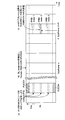
- FIG. 1 is a diagram showing a hierarchical bandwidth configuration defined in LTE-A.
- an LTE-A system having a first system band composed of a plurality of component carriers (basic frequency blocks) and an LTE system having a second system band composed of one component carrier coexist.
- This is a hierarchical bandwidth configuration.
- wireless communication is performed with a variable system bandwidth of 100 MHz or less, and in the LTE system, wireless communication is performed with a variable system bandwidth of 20 MHz or less.
- the system band of the LTE-A system is at least one component carrier with the system band of the LTE system as one unit.
- a mobile terminal apparatus UE (User Equipment) # 1 is a mobile terminal apparatus compatible with the LTE-A system (also compatible with the LTE system) and can support a system band up to 100 MHz.
- UE # 3 is a mobile terminal apparatus compatible with the LTE system (not compatible with the LTE-A system), and can support a system band up to 20 MHz (base band).
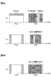
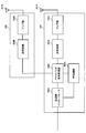
- FIG. 2 is a diagram illustrating an example of carrier aggregation in HetNet.
- the system shown in FIG. 2A is hierarchically configured by a base station eNB (eNodeB) and a plurality of base stations (for example, RRH (Remote Radio Head)).
- a base station eNB eNodeB
- RRH Remote Radio Head
- a small cell small transmission power
- the mobile terminal apparatus UE is located in the small cell of RRH # 1, and communicates with the base station eNB and RRH # 1 by carrier aggregation.
- the carrier aggregation is performed using the component carrier CC # 1 of the base station eNB as the PCell and the component carrier CC # 2 of the base station apparatus RRH # 1 as the SCell.
- RRH is detected by different frequency measurement in a state where the mobile terminal apparatus UE is connected to the base station eNB.
- the mobile terminal apparatus UE is synchronized with PSS / SSS (Primary Synchronization Signal / Secondary Synchronization Signal), which is a synchronization signal, and then the reception quality of different frequencies from each RRH is measured by CRS (Cell-specific Reference Signal). .
- CRS Cell-specific Reference Signal
- a carrier that is not compatible with an existing component carrier may be referred to as an additional carrier type or an extension carrier.
- FIG. 2B shows a state in which the component carrier CC # 1 assigned to the base station eNB and the component carrier CC # 2 assigned to the RRH are both set to the existing carrier type (Legacy carrier type).
- FIG. 2C is a diagram illustrating an example of carrier aggregation using an additional carrier type. CC # 1 assigned to the base station eNB is set to the existing carrier type, and component carrier CC # 2 assigned to the RRH is set to the additional carrier type. 2B and 2C, only CRS, PDCCH, and PDSCH are illustrated for convenience of explanation.
- PDCCH is set to a maximum of 3 symbols from the beginning of one resource block defined by LTE.
- CRS is set so that it does not overlap with other reference signals such as user data and DM-RS (Demodulation-Reference Signal) in one resource block.
- this CRS is used to measure downlink channel quality (CQI) for scheduling and adaptive control, and to measure average channel conditions in downlink for cell search and handover ( Used for mobility measurement).
- the additional carrier type can make PDCCH and CRS untransmitted.
- This additional carrier type is not supported by existing mobile terminal devices (before Rel-10), but is only supported by new mobile terminal devices UE (after Rel-11). Further, the additional carrier type may be no transmission of downlink control channels (PHICH, PCFICH) and no transmission of broadcast information (PBCH, Rel-8 SIB, Paging). Further, it is assumed that the additional carrier type is mainly used in the SCell.
- the CRS when the CRS is not transmitted as the additional carrier type, for example, user-specific DM-RS can be used for data demodulation, and CSI-RS (Channel State Information-Reference Signal) can be used for CSI measurement. .
- CSI-RS Channel State Information-Reference Signal
- an additional carrier type when not transmitting PDCCH, you may transmit FDM type PDCCH.
- the FDM type PDCCH uses a predetermined frequency band of a PDSCH region for downlink data signals as an extended PDCCH region.
- the FDM type PDCCH allocated to this extended PDCCH region is demodulated using DM-RS.
- the extended PDCCH may be referred to as UE-PDCCH.
- Cross-carrier scheduling is a method of transmitting the downlink control channel of the own carrier using another carrier. For example, instead of transmitting the downlink control channel using an additional carrier type carrier, the downlink control channel is transmitted using an existing carrier type carrier.
- the additional carrier type is PHICH (Physical Hybrid-ARQ Indicator Channel) that is not transmitted, retransmission control may be performed using downlink control information (DCI).
- DCI downlink control information
- the additional carrier type may notify the number of OFDM symbols used for the PDCCH by an upper layer signal (Higher layer signaling).
- the additional carrier type may transmit the broadcast information from a carrier of the existing carrier type.
- the additional carrier type may be configured such that at least one of the CRS and the downlink control channel is not transmitted or some signals are reduced.
- the bandwidth of the additional carrier type does not have to be the unit of the system band (base band: 20 MHz) of the LTE system, and can be changed as appropriate.
- interference by CRS is reduced by performing carrier aggregation using an existing carrier type and an additional carrier type. That is, since the CRS can be made non-transmitted in the additional carrier type, the interference of the CRS from the adjacent base station (RRH or the like) can be suppressed, and for example, the downlink signal can be received from the SCell having better reception quality than the PCell. Further, since CRS and PDCCH resources are vacant, the frequency utilization efficiency can be improved by adopting a configuration in which downlink data is transmitted thereto.
- a PUSCH resource is dynamically or periodically secured to an SCell by an upper layer signal, and a PUSCH resource previously secured to the SCell is triggered by downlink scheduling assignment (DL assignment).
- DL assignment downlink scheduling assignment
- a CQI is transmitted together with ACK / NACK using the triggered PUSCH resource in the subframe after the frame.
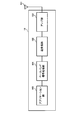
- FIG. 3 illustrates an uplink subframe configuration in which a PUSCH resource is dynamically triggered.
- the mobile terminal apparatus receives a higher layer signal transmitted from the base station and reserves a plurality of PUSCH resources in the SCell for each subframe (FIG. 3 (a)).
- “reserving” a PUSCH resource may be rephrased as “provisionally securing” or “setting” a PUSCH resource.
- provisionally securing or “setting” a PUSCH resource.
- the reserved PUSCH resource is used for data transmission. Can do.
- FIG. 3 shows a state in which three PUSCH resources are reserved per subframe.
- the reserved PUSCH resource is configured in units of physical resource blocks (PRB), and is managed by index numbers (PRBindex1, PRBindex2, PRBindex3).
- the three reserved PUSCH resources (PRBindex1, PRBindex2, PRBindex3) may be shared by a plurality of mobile terminal apparatuses. Since the base station knows the PUSCH resource reserved in the mobile terminal apparatus, when triggering the reserved PUSCH resource for a plurality of mobile terminal apparatuses in the same subframe, the base station is selected from the plurality of reserved PUSCH resources. Trigger reserved PUSCH resources that differ between terminals.
- the base station (for example, SCell) transmits the downlink scheduling assignment on the PDCCH or E-PDCCH in the subframe in which the PDSCH is transmitted to the mobile terminal apparatus.
- the base station sets an index number corresponding to a reserved PUSCH resource for UCI transmission in downlink scheduling assignment.
- the base station transmits a downlink scheduling assignment in which an index number corresponding to the reserved PUSCH resource is set to the mobile terminal apparatus using PDCCH or E-PDCCH. Any reserved PUSCH resource is triggered by the downlink scheduling assignment trigger bit and assigned to the uplink of the SCell.
- the CQI report is an example of a channel quality report and is not limited to the CQI report.
- PUSCH resources may be triggered dynamically or periodically by downlink scheduling assignment.
- ACK / NACK and CSI report are transmitted using the same PUSCH resource.
- CSI and ACK / NACK may be transmitted in the same subframe using PUSCH triggered by downlink scheduling assignment.
- FIG. 4 is a specific example of trigger bits set for downlink scheduling assignment.
- the trigger bit “11” designates an index.
- UCI is transmitted using PUSCH resources dynamically allocated in this way. If the number of trigger bits is 3 bits or more, 4 or more PUSCH resources can be dynamically selected for each subframe.
- the mobile terminal apparatus triggers one of the reserved PUSCH resources used for UCI transmission by the trigger bit set in the downlink scheduling assignment received from the base station (for example, SCell) (FIG. 3 (b)). For example, the mobile terminal apparatus demodulates the PDSCH based on the downlink scheduling assignment included in the subframe received by the SCell, generates ACK / NACK for the PDSCH, and generates CQI indicating the reception quality of the downlink channel in the subframe. taking measurement.
- the base station for example, SCell
- the mobile terminal apparatus demodulates the PDSCH based on the downlink scheduling assignment included in the subframe received by the SCell, generates ACK / NACK for the PDSCH, and generates CQI indicating the reception quality of the downlink channel in the subframe. taking measurement.
- the mobile terminal apparatus receives a subframe (for example, the (n + 4) th subframe after 4 subframes) after a predetermined subframe from the subframe (for example, the nth subframe) in which the downlink scheduling allocation that triggers the dynamic PUSCH resource is detected.
- a subframe for example, the (n + 4) th subframe after 4 subframes
- ACK / NACK and CQI are transmitted to the base station (for example, RRH) that transmitted the downlink scheduling assignment (FIG. 3 (c)).
- the figure shows a state where the PUSCH resource corresponding to PRBindex2 is dynamically selected by the trigger bit “10”.
- the PUSCH resource used for UCI transmission is dynamically triggered by downlink scheduling assignment, it can be used even when there is no uplink data traffic. Since the CQI is used for downlink scheduling in the base station, it is sufficient to be able to trigger the PUSCH resource used for UCI transmission where there is downlink data (PDSCH). Since there is always a PDSCH demodulated by downlink scheduling assignment, the CQI can be transmitted together with the ACK / NACK for that PDSCH using the dynamically triggered PUSCH resource. Although the PUSCH can be triggered by using the uplink scheduling grant, if there is no uplink data traffic, the uplink scheduling grant must be transmitted only for UCI transmission.
- PDSCH downlink data
- the restriction on subframes used for UCI transmission can be relaxed.
- the PUSCH resource used for UCI transmission is only temporarily reserved, the PUSCH resource that does not transmit UCI among the provisionally reserved PUSCH resources can be used for uplink data transmission.
- FIG. 5 illustrates an uplink subframe configuration in which PUSCH resources are periodically triggered.
- PUSCH resources are reserved periodically (for example, every 10 subframes). If UCI transmission occurs, one of the periodically reserved PUSCH resources is triggered, and UCI transmission is performed using the triggered PUSCH resource.
- the mobile terminal apparatus periodically reserves a plurality of PUSCH resources at intervals of a plurality of subframes by an upper layer signal transmitted from a base station (for example, SCell) (FIG. 5 (a)).
- FIG. 5 shows a state in which three PUSCH resources are periodically reserved for one uplink subframe.
- the periodic PUSCH resource (PRBindex1, PRBindex2, PRBindex3) may be shared by a plurality of mobile terminal apparatuses. Since the base station knows periodically reserved PUSCH resources, when triggering periodic PUSCH resources for a plurality of mobile terminal apparatuses in the same subframe, different periodic PUSCH resources between terminals are used. Specify multiple mobile terminals.
- the base station (for example, SCell) transmits the downlink scheduling assignment on the PDCCH or E-PDCCH in the subframe in which the PDSCH is transmitted to the mobile terminal apparatus.
- this downlink scheduling assignment an index number corresponding to the periodic PUSCH resource, a subframe number that triggers the periodic PUSCH resource, and a repetition period in the time direction of the periodic PUSCH resource are set.
- the base station transmits a downlink scheduling assignment in which an index number, a subframe number, and a repetition period corresponding to the periodic PUSCH resource are set to the mobile terminal apparatus using PDCCH or E-PDCCH. Either the subframe number or the repetition period may be notified.
- the periodic PUSCH resource used for UCI transmission is triggered by the trigger bit set in the downlink scheduling assignment (FIG. 5 (b)).
- the mobile terminal apparatus demodulates the PDSCH based on a downlink scheduling assignment included in a subframe with an SCell, generates an ACK / NACK for the PDSCH, and measures a CQI indicating the reception quality of the downlink channel in the subframe. To do.
- the mobile terminal apparatus reserves periodic PUSCH resources based on the index number, subframe number, and repetition period included in the downlink scheduling assignment (for example, every 10 subframes).
- the mobile terminal apparatus / NACK and CQI are transmitted to the base station (for example, RRH) that transmitted the downlink scheduling assignment using the periodic PUSCH resource (FIG. 5 (c)).
- FIG. 6A shows a PCell to which an existing carrier type (Rel-8) is applied and an SCell to which an additional carrier type is applied.
- the additional carrier type is applied to the SCell
- the E-PDCCH and the PDSCH demodulated based on the E-PDCCH are transmitted from the RRH.
- the RRH triggers a dynamic or periodic PUSCH resource for transmitting CQI to the mobile terminal apparatus
- the mobile terminal apparatus receives the SCell downlink signal, demodulates the E-PDCCH included in the downlink signal, and detects downlink scheduling assignment.
- the PDSCH is demodulated based on the downlink scheduling assignment, and ACK / NACK for the PDSCH is generated. If CQI reporting is triggered by downlink scheduling assignment, the CQI of the downlink signal in the additional carrier type is measured in a predetermined frequency unit. At this time, if the trigger bit is set in the downlink scheduling assignment, the dynamic or periodic PUSCH resource of the PRB index specified by the trigger bit is triggered. CQI and ACK / NACK are transmitted using dynamic or periodic PUSCH resources triggered on the uplink of SCell.
- a trigger bit indicating the index number of the dynamic or periodic PUSCH resource is set in the downlink scheduling allocation included in the PDCCH.
- the mobile terminal apparatus receives the SCell downlink signal, demodulates the PDCCH, and triggers the dynamic or periodic PUSCH resource of the PRB index specified by the trigger bit if the trigger bit is set in the downlink scheduling assignment. (Assignment of PUSCH resource corresponding to PRBindex).
- the dynamic or periodic PUSCH resource may be set only in one of SCell and PCell, or may be set in both SCell and PCell.
- PCell is mainly responsible for ensuring coverage
- SCell is expected to realize a high transmission rate in a local area where traffic is high. Therefore, an increase in UCI information such as ACK / NACK is expected in a situation where SCell is added. For this reason, in a situation where an SCell is added in HetNet, it is desirable to set a dynamic or periodic PUSCH resource for the SCell from the viewpoint of suppressing the CQI drop frequency.
- the CQI drop frequency can be set by setting the dynamic or periodic PUSCH resource to PCel as in the existing PUCCH. Can be suppressed.
- signal resource information of the dynamic or periodic PUSCH resource to be reserved together with an upper layer signal requesting the mobile terminal apparatus to add the SCell It is possible. If the communication by PCell is established between the base station and the mobile terminal device in advance, and the quality of the SCell reported from the mobile terminal device exceeds the threshold, the SCell is sent to the mobile terminal device by the higher layer signal. Add At this time, the resource information (PRB index, subframe number, or any or all of the period) of the dynamic or periodic PUSCH resource is included in the upper layer signal that requests the mobile terminal apparatus to add the SCell.
- independent resources for example, different PRB indexes
- SCell and PCell when the system bandwidth is the same (for example, PCell and The number of RBs of the SCell is the same (for example, 50 RBs each), and a common resource (for example, PRB # 0-49 for both PCell and SCell) may be used.
- the mobile terminal apparatus secures dynamic or periodic PUSCH resources in the uplink of PCell and SCell, and dynamic or periodic PUSCH resources triggered by PCell such as ACK / NACK and CQI for PDSCH received by PCell Or it transmits using PUCCH resource and transmits UCI, such as ACK / NACK and CQI with respect to PDSCH received by SCell, using the dynamic or periodic PUSCH resource triggered by SCell.
- the dynamic or periodic PUSCH resource can be used as a resource for transmitting only ACK / NACK in the uplink.
- a downlink scheduling assignment that triggers a dynamic or periodic PUSCH resource is transmitted to the mobile terminal apparatus by PDCCH or E-PDCCH of SCell.
- the mobile terminal apparatus can transmit ACK / NACK using the dynamic or periodic PUSCH resource triggered by the SCell.
- PCell PUCCH or SCell PUCCH may be used as a resource for transmitting only ACK / NACK in the uplink (FIG. 6B).
- the PDSCH is transmitted only from the downlink of the SCell, if the PUCCH is defined in the SCell, it may be used, and if it is not defined, the PCell may be used.
- CQI CQI is not triggered, it is necessary to specify in the specification whether transmission is performed using PUCCH or transmission using ACK / NACK using dynamic or periodic PUSCH resources.
- the PUCCH (format 1a / 1b) is transmitted from the uplink of the PCell.
- ACK / NACK is transmitted using PUCCH (format 1a / 1b) of PCell.
- the PUCCH (format 1a / 1b) is transmitted from the uplink of the SCell.
- ACK / NACK is transmitted using PUCCH (format 1a / 1b) of SCell.
- UCI is transmitted from either uplink PCell or uplink SCell using the carrier aggregation PUCCH format. Which cell is used is notified to the mobile terminal apparatus by an upper layer signal.
- the dynamic or periodic PUSCH of the SCell is preferentially used. And transmit UCI of PCell and SCell. This is because the PUSCH resource can transmit more bit data than the PUCCH resource. It is specified beforehand that the dynamic or periodic PUSCH of the SCell has priority according to the specification. In Rel-10, the cell number of PCell is “0”, and the cell number of SCell is “1”, “2”.
- ACK / NACK is transmitted using the PUSCH triggered by the uplink scheduling grant.
- UCI (ACK / NACK + CQI) is transmitted using the PUSCH triggered according to the uplink scheduling grant.
- the PUSCH When the PUSCH is assigned by the uplink scheduling grant, the PUSCH is transmitted by the PRB having a good channel quality based on the scheduling, so it is desirable to transmit by the PUSCH.
- the CQI report when the CQI report is not triggered by the uplink scheduling grant, but is triggered by the downlink scheduling assignment, it is treated as an erroneous setting. In addition, when the CQI report is triggered by both the uplink scheduling grant and the downlink scheduling assignment, it is also treated as an erroneous setting.
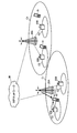
- FIG. 8 is an explanatory diagram of the system configuration of the wireless communication system according to the present embodiment.
- the radio communication system shown in FIG. 8 is a system including, for example, an LTE system or a successor system, and supports the above-described functions.
- carrier aggregation in which a plurality of basic frequency blocks having the system band of the LTE system as one unit is integrated is used.
- this wireless communication system may be called IMT-Advanced or 4G.
- the wireless communication system is HetNet, and a base station device (first base station device) 20A in cell C1 and a plurality of base station devices (first devices in cell C2 provided in cell C1).
- 2 base station apparatus) 20B a hierarchical network is constructed.
- the base station device 20A is a so-called macro base station device and covers a large cell C1.
- the base station apparatus 20B is a so-called RRH base station apparatus, and a small cell C2 is locally formed in the cell C1.
- the base station device 20A and each base station device 20B are connected to each other by wired connection or wireless connection.
- the mobile terminal apparatus 10 can communicate with the base station apparatuses 20A and 20B in the cells C1 and C2, respectively.
- the base station device 20A is connected to the core network 30 via a higher station device.
- the upper station device includes, but is not limited to, an access gateway device, a radio network controller (RNC), a mobility management entity (MME), and the like.
- Each mobile terminal device 10 includes an existing mobile terminal device (before Rel-10) and a new mobile terminal device (after Rel-11), but in the following, mainly a new mobile terminal device (after Rel-11) ).
- RNC radio network controller
- MME mobility management entity
- Each mobile terminal device 10 includes an existing mobile terminal device (before Rel-10) and a new mobile terminal device (after Rel-11), but in the following, mainly a new mobile terminal device (after Rel-11) ).
- each mobile terminal device 10 performs radio communication with the base station devices 20A and 20B.
- user devices UE: UE including both mobile terminal devices and fixed terminal devices. User Equipment).
- This wireless communication system supports carrier aggregation suitable for HetNet.
- the mobile terminal apparatus 10 receives a downlink signal from each base station apparatus 20B while being connected to the base station apparatus 20A (PCell).
- the mobile terminal apparatus 10 measures the signal quality from each base station apparatus 20B based on the downlink signal, and feeds back the measurement result to the base station apparatus 20A.
- the base station device 20A detects the base station device 20B having good reception quality as an SCell, and performs carrier aggregation.
- OFDMA Orthogonal Frequency Division Multiple Access
- SC-FDMA Single Carrier Frequency Division Multiple Access
- OFDMA is a multi-carrier transmission scheme that performs communication by dividing a frequency band into a plurality of narrow frequency bands (subcarriers) and mapping data to each subcarrier.
- SC-FDMA is a single carrier transmission method that reduces interference between terminals by dividing a system band into bands each consisting of one or continuous resource blocks for each terminal, and a plurality of terminals using different bands. .
- the downlink communication channel includes PDSCH shared by each mobile terminal apparatus 10 and downlink L1 / L2 control channels (PDCCH, PCFICH, PHICH). User data and higher control information are transmitted by the PDSCH. PDSCH and PUSCH scheduling information and the like are transmitted by the PDCCH.
- the number of OFDM symbols used for PDCCH is transmitted by PCFICH (Physical Control Format Indicator Channel).
- the HARQ ACK / NACK for PUSCH is transmitted by PHICH (Physical Hybrid-ARQ Indicator Channel).
- the uplink communication channel has PUSCH as an uplink data channel shared by each mobile terminal apparatus and PUCC which is an uplink control channel. User data and higher control information are transmitted by this PUSCH. Also, downlink CQI, ACK / NACK, and the like are transmitted by PUCCH.
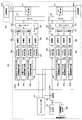
- base station apparatuses 20A and 20B the overall configuration of base station apparatuses 20A and 20B according to the present embodiment will be described. Note that baseband processing is not performed in the base station apparatus 20B, and the base station apparatus 20B receives the baseband signal from the base station apparatus 20A and notifies the mobile terminal apparatus 10 thereof.
- the base station apparatus 20A includes a transmission / reception antenna 201A, an amplifier unit 202A, a transmission / reception unit 203A, a baseband signal processing unit 204A, a call processing unit 205A, and a transmission path interface 206A.
- the base station device 20B includes a transmission / reception antenna 201B, an amplifier unit 202B, and a transmission / reception unit 203B. Transmission data transmitted from the base station apparatuses 20A and 20B to the mobile terminal apparatus 10 via the downlink is input from the higher station apparatus to the baseband signal processing unit 204A via the transmission path interface 206A.
- the downlink data channel signal is transmitted from the RCP layer, such as PDCP layer processing, user data division / combination, RLC (Radio Link Control) retransmission control transmission processing, and MAC (Medium Access).
- RCP layer such as PDCP layer processing, user data division / combination, RLC (Radio Link Control) retransmission control transmission processing, and MAC (Medium Access).
- Control Retransmission control, for example, HARQ transmission processing, scheduling, transmission format selection, channel coding, inverse fast Fourier transform (IFFT) processing, and precoding processing are performed. Also, transmission processing such as channel coding and inverse fast Fourier transform is performed on the downlink control channel signal.
- the baseband signal processing unit 204A notifies the mobile terminal device 10 connected to the same cell of the control information for each mobile terminal device 10 to perform wireless communication with the base station devices 20A and 20B through the broadcast channel.
- the information for communication in the cell includes, for example, system bandwidth in uplink or downlink, and root sequence identification information (Root Sequence) for generating a random access preamble signal in PRACH (Physical Random Access Channel). Index) etc. are included.
- a baseband signal corresponding to the PCell component carrier CC # 1 is output from the baseband signal processing unit 204A to the transmission / reception unit 203A, and from the baseband signal processing unit 204A to the transmission / reception unit 203B of the base station apparatus 20B.
- a baseband signal corresponding to the SCell component carrier CC # 2 is output through the optical fiber.
- the transmission / reception units 203A and 203B convert the baseband signal output from the baseband signal processing unit 204A to a radio frequency band.
- the amplifier units 202A and 202B amplify the frequency-converted radio frequency signal and transmit the amplified signal using the transmission / reception antennas 201A and 201B.
- radio frequency signals received by the transmission / reception antennas 201A and 201B of the base station apparatuses 20A and 20B are amplified by the amplifier sections 202A and 202B.
- the frequency is converted by the transmission / reception units 203A and 203B, converted into a baseband signal, and input to the baseband signal processing unit 204A.
- the baseband signal processing unit 204A performs FFT processing, IDFT processing, error correction decoding, MAC retransmission control reception processing, RLC layer, and PDCP layer reception processing on transmission data included in the input baseband signal. Made.
- the baseband signal is transferred to the upper station apparatus via the transmission path interface 206A.
- the call processing unit 205A performs call processing such as communication channel setting and release, state management of the base station apparatuses 20A and 20B, and management of radio resources.
- the mobile terminal apparatus 10 includes a transmission / reception antenna 101, an amplifier unit 102, a transmission / reception unit 103 (reception unit), a baseband signal processing unit 104, and an application unit 105.
- a radio frequency signal received by the transmission / reception antenna 101 is amplified by the amplifier unit 102, frequency-converted by the transmission / reception unit 103, and converted into a baseband signal.
- the baseband signal is subjected to FFT processing, error correction decoding, retransmission control reception processing, and the like by the baseband signal processing unit 104.
- downlink user data is transferred to the application unit 105.
- the application unit 105 performs processing related to layers higher than the physical layer and the MAC layer. Also, broadcast information in the downlink data is also transferred to the application unit 105.
- uplink transmission data is input from the application unit 105 to the baseband signal processing unit 104.
- the baseband signal processing unit 104 performs mapping processing, retransmission control (H-ARQ) transmission processing, channel coding, DFT processing, and IFFT processing.
- the transmission / reception unit 103 converts the baseband signal output from the baseband signal processing unit 104 into a radio frequency band. Thereafter, the signal is amplified by the amplifier unit 102 and transmitted from the transmission / reception antenna 101.
- FIG. 11 is a functional block diagram of a baseband signal processing unit 204A and some upper layers included in the base station apparatus 20A according to the present embodiment, and mainly includes functional blocks of transmission processing of the baseband signal processing unit 204A. Show. Transmission data for the mobile terminal apparatus 10 under the control of the base station apparatus 20A is transferred from the higher station apparatus to the base station apparatus 20A.
- the base station device 20A is illustrated.
- the base station device 20A shows a configuration that can support carrier aggregation of two component carriers CC # 1 and CC # 2.
- the number of CCs used by each base station apparatus 20 is not limited to this.
- the control information generation unit 300 generates upper control information to be notified to the mobile terminal apparatus 10 by upper layer signaling for each user.
- the upper control information includes resource information for reserving dynamic or periodic PUSCH in the uplink of component carriers CC # 1 and CC # 2 (for example, when reserving periodic PUSCH, PRBindex, subframe number, Period).
- the data generation unit 301 outputs the transmission data transferred from the higher station apparatus as user data for each user.
- the component carrier selection unit 302 selects a component carrier used for wireless communication with the mobile terminal device 10 for each mobile terminal device 10.
- the component carrier CC # 1 of the base station device 20A is set to PCell, and the SCell is selected from the other base station device 20B via the optical fiber 319.
- the base station apparatus 20A notifies the mobile terminal apparatus 10 of addition / reduction of component carriers by higher layer signaling, and receives an application completion message from the mobile terminal apparatus 10.
- the scheduling unit 310 controls the allocation of component carriers to the subordinate mobile terminal devices 10 according to the communication quality of the entire system band.
- the scheduling unit 310 performs scheduling while distinguishing between LTE terminal users and LTE-A terminal users.
- Scheduling section 310 receives data to be transmitted from the upper station apparatus and a retransmission instruction, and receives a channel estimation value and a CQI of a resource block from a receiving section that measures an uplink signal.
- the scheduling unit 310 performs scheduling of the downlink control channel signal and the downlink shared channel signal while referring to the input retransmission instruction, channel estimation value, and CQI.
- the propagation path in wireless communication varies depending on the frequency due to frequency selective fading. Therefore, scheduling section 310 instructs a resource block (mapping position) with good communication quality for each subframe for downlink data to each mobile terminal apparatus 10 (referred to as adaptive frequency scheduling).
- adaptive frequency scheduling the mobile terminal apparatus 10 with good channel quality is selected for each resource block. Therefore, the scheduling unit 310 indicates a resource block (mapping position) using the CQI for each resource block fed back from the mobile terminal apparatus 10.
- the scheduling unit 310 instructs a resource block with good communication quality for each subframe with respect to control information transmitted on the PDCCH (or E-PDCCH) by adaptive frequency scheduling. For this reason, the scheduling unit 310 indicates a resource block (mapping position) using the CQI for each resource block fed back from each mobile terminal apparatus 10. Also, an MCS (coding rate, modulation scheme) that satisfies a predetermined block error rate with the allocated resource block is determined. Parameters satisfying the MCS (coding rate, modulation scheme) determined by the scheduling unit 310 are set in the channel coding units 303 and 308 and the modulation units 304 and 309. The applied frequency scheduling is performed not only for the base station apparatus 20A but also for the base station apparatus 20B via the optical fiber 319.
- MCS coding rate, modulation scheme
- the baseband signal processing unit 204A includes a channel encoding unit 303, a modulation unit 304, and a mapping unit 305 corresponding to the maximum user multiplexing number N within one component carrier.
- the channel coding unit 303 channel-codes the downlink shared data channel (PDSCH) configured by the downlink data (including some higher control signals) output from the data generation unit 301 for each user.
- the modulation unit 304 modulates channel-coded user data for each user.
- the mapping unit 305 maps the modulated user data to radio resources.
- the baseband signal processing unit 204A includes a downlink control information generation unit 306 that generates downlink control information, a channel encoding unit 308, and a modulation unit 309.
- the uplink shared data channel control information generator 306b generates an uplink scheduling grant (UL Grant) for controlling the uplink data channel (PUSCH).
- the uplink scheduling grant is generated for each user.
- the downlink shared data channel control information generation unit 306c generates a downlink scheduling assignment (DL assignment) for controlling the downlink data channel (PDSCH).
- the downlink scheduling assignment is generated for each user.
- the baseband signal processing unit 204A (CC # 2) addressed to the base station apparatus 20B sets a trigger bit based on FIG. 4 for downlink scheduling assignment.
- a trigger bit is set for downlink scheduling assignment at the timing of triggering the CQI report to the mobile terminal apparatus 10. For example, as shown in FIG. 3, when UCI transmission is performed using a PUSCH resource corresponding to PRBindex2, “10” is set as a trigger bit.
- a trigger bit is set for downlink scheduling assignment based on FIG.
- a trigger bit is set for downlink scheduling assignment at the timing of triggering the CQI report to the mobile terminal apparatus 10. For example, as shown in FIG. 3, when UCI transmission is performed using a PUSCH resource corresponding to PRBindex2, “10” is set as a trigger bit. When dynamic or periodic PUSCH used for CIU transmission is not triggered, “00” is set as a trigger bit. Also, the common channel control information generation unit 306a generates common control channel control information that is downlink control information common to users.
- the control information modulated for each user by the modulation unit 309 is multiplexed by the control channel multiplexing unit 314 and further interleaved by the interleaving unit 315.
- the control signal output from the interleaving unit 315 and the user data output from the mapping unit 305 are input to the IFFT unit 316 as downlink channel signals.
- the IFFT unit 316 receives the control signal from the interleaving unit 315 and the user data from the mapping unit 305 as downlink channel signals. Further, the IFFT unit 316 further receives a downlink reference signal. For the downlink reference signal, CRS for channel estimation, DM-RS for downlink demodulation, and CSI-RS for CSI measurement may be generated. The IFFT unit 316 performs inverse fast Fourier transform on the downlink channel signal and downlink reference signal to convert the frequency domain signal into a time-series signal. The cyclic prefix insertion unit 317 inserts a cyclic prefix into the time-series signal of the downlink channel signal. The cyclic prefix functions as a guard interval for absorbing a difference in multipath propagation delay. The transmission data to which the cyclic prefix is added is sent to the transmission / reception units 203A and 203B.
- all subframes may be set as an additional carrier type, a predetermined subframe may be set as an additional carrier type, and the remaining subframes may be set as an existing carrier type.
- a new mobile terminal device Rel-11 or later
- an existing mobile terminal device before Rel-10 is connected to the component carrier CC # 2 assigned to the base station device 20B during the period of the existing carrier type. Can be made.
- FIG. 12 is a functional block diagram of the baseband signal processing unit 104 of the mobile terminal apparatus 10, and shows functional blocks of an LTE-A terminal that supports an additional carrier type.
- the CP removal section 401 removes the CP from the downlink signal received as received data from the base station apparatuses 20A and 20B.
- the downlink signal from which the CP is removed is input to the FFT unit 402.
- the FFT unit 402 performs fast Fourier transform (FFT) on the downlink signal, converts the signal from the time domain to the signal in the frequency domain, and inputs the signal to the demapping unit 403.
- the demapping unit 403 demaps the downlink signal, and extracts multiplex control information, user data, and higher control signal in which a plurality of control information is multiplexed from the downlink signal. Note that the demapping process by the demapping unit 403 is performed based on a higher control signal input from the application unit 105.
- the multiplex control information output from the demapping unit 403 is deinterleaved by the deinterleaving unit 404.
- the baseband signal processing unit 104 also includes a downlink control information demodulation unit 405 that demodulates downlink control information, a data demodulation unit 406 that demodulates downlink shared data, a channel estimation unit 407, a reception quality measurement unit (measurement unit) 408, an allocation Part 409.
- the allocation unit 409 may be configured not to be included in the baseband signal processing unit 104 as will be described later.
- the downlink control information demodulation section 405 demodulates the common channel control information demodulation section 405a that demodulates the common control channel control information from the multiplexed control information, and the uplink shared data channel control information from the multiplexed control information.
- an uplink shared data channel control information demodulator 405b, and a downlink shared data channel control information demodulator 405c that demodulates the downlink shared data channel control information from the multiplexed control information.
- the common channel control information demodulator 405a extracts common control channel control information, which is common control information for users, through blind decoding processing, demodulation processing, channel decoding processing, and the like of the common search space of the downlink control channel (PDCCH). .
- the common control channel control information includes downlink channel quality information (CQI), is input to the mapping unit 415, and is mapped as part of transmission data to the base station apparatus 20.
- CQI downlink channel quality information
- the uplink shared data channel control information demodulator 405b performs uplink shared data channel control information (for example, UL Grant) through blind decoding processing, demodulation processing, channel decoding processing, etc. of the user-specific search space of the downlink control channel (PDCCH). ).
- the demodulated uplink shared data channel control information is input to the mapping unit 415 and used for uplink shared data channel (PUSCH) control.
- the downlink shared data channel control information demodulating section 405c performs user-specific downlink shared data channel control information (for example, blind decoding processing, demodulation processing, channel decoding processing, etc.) for the user dedicated search space of the downlink control channel (PDCCH). , Downlink scheduling allocation).
- the PUSCH trigger bit is set for downlink scheduling assignment.
- the demodulated downlink shared data channel control information is input to the data demodulating unit 406 and used for controlling the downlink shared data channel (PDSCH).
- the data demodulator 406 includes a downlink shared data demodulator 406a that demodulates user data and higher control signals, and a downlink common channel data demodulator 406b that demodulates downlink common channel data.
- the downlink shared data demodulator 406a acquires user data and higher control information based on the downlink shared data channel control information input from the downlink shared data channel control information demodulator 405c.
- An SCell of an additional carrier type is added by a request to add an SCell included in the higher control information.
- the upper control information includes the resource information of the dynamic or periodic PUSCH resource
- the dynamic or periodic PUSCH resource is reserved according to the resource information. In the example shown in FIG. 4, PUSCH resources of PRB indexes 1, 2, and 3 are reserved.
- the downlink common channel data demodulation unit 406b demodulates the downlink common channel data based on the uplink shared data channel control information input from the uplink shared data channel control information demodulation unit 405b.
- the data demodulation unit 406 performs derate matching by switching the rate matching pattern according to the carrier type of the component carrier. For example, in an additional carrier type component carrier, demodulation processing is appropriately performed in consideration of user data allocated to CRS and PDCCH resources.
- the channel estimation unit 407 performs channel estimation using a user-specific reference signal (DM-RS) or a cell-specific reference signal (CRS).
- DM-RS user-specific reference signal
- CRS cell-specific reference signal
- the channel estimation unit 407 determines the estimated channel variation from the common control channel control information demodulation unit 405a, the uplink shared data channel control information demodulation unit 405b, the downlink shared data channel control information demodulation unit 405c, and the downlink shared data demodulation unit 406a. Output to.
- These demodulation units perform demodulation processing using the estimated channel fluctuation and demodulation reference signal.
- the reception quality measurement unit 408 measures CQI that is an indicator indicating the reception quality of the downlink channel.
- Reception quality measuring section 408 outputs the reception quality measurement result to mapping section 415 and feeds back to base station apparatus 20A.
- the measurement result of the reception quality may be directly fed back from the mobile terminal apparatus 10 to the base station apparatus 20A, or may be fed back from the mobile terminal apparatus 10 to the base station apparatus 20A via the base station apparatus 20B.
- the allocation unit 409 determines PUSCH resources to be reserved in the SCell based on the upper layer signal demodulated by the downlink shared data demodulation unit 406a.
- a plurality of PUSCH resources can be reserved for each subframe by an upper layer signal (see FIG. 3). Also, depending on the upper layer signal, a plurality of PUSCH resources can be reserved at a plurality of subframe intervals (see FIG. 5).
- the allocation unit 409 is designated from the reserved PUSCH resources based on the trigger bits (see FIG. 4) included in the downlink scheduling allocation demodulated by the downlink shared data channel control information demodulation unit 405c. Trigger PUSCH resource.
- the PUSCH resource specified by the trigger bit included in the downlink scheduling assignment is assigned to the SCell, for example.
- ACK / NACK and CQI report are transmitted together to the base station (RRH) using the PUSCH resource triggered in the uplink of the SCell.
- the allocation unit 409 handles PUSCH with uplink scheduling grant and PDSCH with downlink scheduling allocation as follows.
- ACK / NACK is transmitted using the PUSCH triggered by the uplink scheduling grant.
- the USCH (ACK / NACK + CQI) is transmitted using the PUSCH triggered according to the uplink scheduling grant.
- the uplink scheduling grant does not trigger CQI reporting, but it is misconfigured when triggered by downlink scheduling assignment, and when both uplink scheduling grant and downlink scheduling assignment trigger CQI reporting. Treat as.
- the assigning unit 409 ACKs the PDSCH assigned by the downlink scheduling assignment. / NACK can be transmitted from the SCell using any of the reserved PUSCH resources.
- the allocation unit 409 uses the PUSCH or the PUCCH assigned to the uplink of the PCell for the ACK / NACK and / or CQI report for the PDSCH received by the PCell. To transmit in a predetermined subframe. Moreover, you may transmit the ACK / NACK with respect to PDSCH received by SCell, and a CQI report by the same sub-frame as PCell using PUSCH allocated to the uplink of SCell.
- the allocation unit 409 transmits the ACK / NACK and the CQI report by the PDSCH allocated to the uplink of the SCell by the PUSCH allocated to the uplink of the PCell. It is desirable to prioritize UCI transmission.
- the allocating unit 409 has two types of UCI transmission by the PUSCH allocated to the uplink of the PCell and UCI transmission by the PUSCH allocated to the uplink of the SCell.
- the carrier having the smallest cell number among the two carriers is given priority.
- the allocation part 409 may notify the priority of SCell when the transmission time of the uplink control information by PCell and SCell overlaps with an upper layer signal in advance.
- the baseband signal processing unit 104 includes a data generation unit 411, a channel encoding unit 412, a modulation unit 413, a DFT unit 414, a mapping unit 415, an IFFT unit 416, and a CP insertion unit 417 as functional blocks of the transmission processing system. I have.
- the data generation unit 411 generates transmission data from the bit data input from the application unit 105.
- the channel coding unit 412 performs channel coding processing such as error correction on the transmission data, and the modulation unit 413 modulates the channel-coded transmission data with QPSK or the like.
- the DFT unit 414 performs discrete Fourier transform on the modulated transmission data.
- Mapping section 415 maps each frequency component of the data symbol after DFT to a subcarrier position designated by base station apparatuses 20A and 20B.
- the IFFT unit 416 performs inverse fast Fourier transform on input data corresponding to the system band to convert it into time series data, and the CP insertion unit 417 inserts a cyclic prefix into the time series data at data delimiters.
- a PUSCH resource is reserved for each uplink subframe of the SCell or at a predetermined cycle by an upper layer signal, and an arbitrary reserved PUSCH resource is set by a trigger bit included in the downlink scheduling assignment.
- a CQI report can be transmitted together with ACK / NACK using the PUSCH resource.
- an arbitrary reserved PUSCH resource can be triggered by downlink scheduling allocation and resource allocation to the uplink can be performed. Therefore, the frequency of CQI dropping at the time of carrier aggregation in HetNet is reduced. It is possible to construct a system that can suppress and transmit UCI with high efficiency.
- the present invention is not limited to the above embodiment, and can be implemented with various modifications.
- the number of carriers, the carrier bandwidth, the signaling method, the type of additional carrier type, the number of processing units, and the processing procedure in the above description can be changed as appropriate. It is. Other modifications can be made without departing from the scope of the present invention.
Abstract
La présente invention a pour objectif de déclencher un PUSCH de façon dynamique ou périodique, et de transmettre efficacement des UCI à une SCell, durant une agrégation de porteuses dans un HetNet. Afin d'atteindre l'objectif visé, la présente invention se rapporte à un système de communication comprenant un dispositif formant terminal mobile : qui réserve, dans une seconde porteuse, des ressources pour un canal physique partagé sur la liaison montante, au moyen de signaux de couche supérieure ; et qui transmet, à un second dispositif formant station de base, au moyen de l'une des ressources de canal physique partagé sur la liaison montante réservées, des données de contrôle sur la liaison montante combinant un ACK/NACK pour un canal physique partagé sur la liaison descendante alloué par une allocation de ressources de programmation sur la liaison descendante, et un rapport de CQI déclenché par l'allocation de ressources de programmation sur la liaison descendante.
Priority Applications (3)
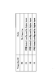
| Application Number | Priority Date | Filing Date | Title |
|---|---|---|---|
| CN201380015196.5A CN104205972A (zh) | 2012-03-19 | 2013-02-28 | 通信系统、基站装置、移动终端装置以及通信方法 |
| US14/386,185 US9420593B2 (en) | 2012-03-19 | 2013-02-28 | Communication system, base station apparatus, mobile terminal apparatus and communication method |
| EP13763945.6A EP2830375B1 (fr) | 2012-03-19 | 2013-02-28 | Système de communication, dispositif formant terminal mobile et procédé de communication |
Applications Claiming Priority (2)
| Application Number | Priority Date | Filing Date | Title |
|---|---|---|---|
| JP2012-062689 | 2012-03-19 | ||
| JP2012062689A JP5940850B2 (ja) | 2012-03-19 | 2012-03-19 | 通信システム、基地局装置、移動端末装置及び通信方法 |
Publications (1)
| Publication Number | Publication Date |
|---|---|
| WO2013140987A1 true WO2013140987A1 (fr) | 2013-09-26 |
Family
ID=49222450
Family Applications (1)
| Application Number | Title | Priority Date | Filing Date |
|---|---|---|---|
| PCT/JP2013/055482 WO2013140987A1 (fr) | 2012-03-19 | 2013-02-28 | Système de communication, dispositif formant station de base, dispositif formant terminal mobile et procédé de communication |
Country Status (5)
| Country | Link |
|---|---|
| US (1) | US9420593B2 (fr) |
| EP (1) | EP2830375B1 (fr) |
| JP (1) | JP5940850B2 (fr) |
| CN (1) | CN104205972A (fr) |
| WO (1) | WO2013140987A1 (fr) |
Cited By (1)
| Publication number | Priority date | Publication date | Assignee | Title |
|---|---|---|---|---|
| CN113518465A (zh) * | 2018-04-04 | 2021-10-19 | 北京小米移动软件有限公司 | 调度请求传输方法和调度请求传输装置 |
Families Citing this family (36)
| Publication number | Priority date | Publication date | Assignee | Title |
|---|---|---|---|---|
| JP5059118B2 (ja) * | 2006-10-23 | 2012-10-24 | インターデイジタル テクノロジー コーポレーション | 共有チャネルを介してチャネル品質指標を送信するための方法および装置 |
| WO2015020018A1 (fr) * | 2013-08-09 | 2015-02-12 | 京セラ株式会社 | Terminal d'utilisateur, réseau à accès sans fil et procédé de commande de communication |
| US20150119056A1 (en) * | 2013-10-30 | 2015-04-30 | Electronics And Telecommunications Research Institute | Method of device-to-device communication and method of controlling device-to-device communication |
| JP2015088997A (ja) | 2013-10-31 | 2015-05-07 | 株式会社Nttドコモ | 移動局 |
| US9900923B2 (en) * | 2013-11-01 | 2018-02-20 | Qualcomm Incorporated | Techniques for using carrier aggregation in dual connectivity wireless communications |
| JP6509853B2 (ja) | 2013-11-19 | 2019-05-08 | エルジー エレクトロニクス インコーポレイティド | ランダムアクセス手順を実行する方法 |
| JP2015115887A (ja) * | 2013-12-13 | 2015-06-22 | 富士通株式会社 | 基地局及びセル選択方法 |
| RU2678508C2 (ru) * | 2014-01-29 | 2019-01-29 | Хуавей Текнолоджиз Ко., Лтд. | Способ передачи данных и устройство связи |
| US9860914B2 (en) * | 2014-02-10 | 2018-01-02 | Qualcomm Incorporated | Handling FDD and TDD timing offset in FDD and TDD CA in LTE |
| KR20170092648A (ko) | 2014-12-12 | 2017-08-11 | 캐논 가부시끼가이샤 | 통신 장치, 통신 장치의 제어 방법, 및 컴퓨터 프로그램 |
| EP3258727B1 (fr) * | 2015-03-16 | 2019-12-04 | Huawei Technologies Co., Ltd. | Procédé de transmission d'informations et équipement d'utilisateur |
| CN113347647A (zh) * | 2015-03-20 | 2021-09-03 | 株式会社Ntt都科摩 | 终端、由终端执行的方法和基站装置 |
| RU2679881C1 (ru) * | 2015-06-12 | 2019-02-14 | Телефонактиеболагет Лм Эрикссон (Пабл) | Мобильность для систем с формированием диаграммы направленности |
| EP3806379A1 (fr) * | 2015-07-08 | 2021-04-14 | Apple Inc. | Équipement d'utilisateur (eu) et procédés de communication utilisant la transmission et la réception directionnelles |
| KR102340499B1 (ko) | 2015-09-04 | 2021-12-17 | 삼성전자 주식회사 | 무선통신 시스템에서 상향링크 전송전력 제어 방법 및 장치 |
| US10499384B2 (en) | 2015-09-17 | 2019-12-03 | Intel IP Corporation | Transmission of uplink control information in wireless systems |
| US11202282B2 (en) * | 2015-12-16 | 2021-12-14 | Qualcomm Incorporated | Contention-based physical uplink shared channel |
| US11234218B2 (en) * | 2016-01-25 | 2022-01-25 | Qualcomm Incorporated | Descriptor channel designs for uplink channels in a shared radio frequency spectrum band |
| US20190110305A1 (en) * | 2016-03-24 | 2019-04-11 | Ntt Docomo, Inc. | Radio base station, remote device, communication control method |
| JP6435007B2 (ja) * | 2016-04-01 | 2018-12-05 | 華碩電腦股▲ふん▼有限公司 | ワイヤレス通信システムにおける設定されたリソースを使用して送信を改善する方法及び装置 |
| US10306606B2 (en) * | 2016-05-20 | 2019-05-28 | Qualcomm Incorporated | Decoupled transmissions of channel quality feedback and acknowledgement/negative-acknowledgement feedback |
| JP6410774B2 (ja) * | 2016-10-04 | 2018-10-24 | 株式会社Nttドコモ | 移動局 |
| WO2018084610A1 (fr) * | 2016-11-03 | 2018-05-11 | 엘지전자(주) | Procédé de transmission de canal de liaison montante dans un système de communication sans fil, et appareil associé |
| CN113726492A (zh) * | 2017-02-04 | 2021-11-30 | 华为技术有限公司 | 终端、网络设备和通信方法 |
| US11245495B2 (en) * | 2017-06-19 | 2022-02-08 | Lg Electronics Inc. | Method for HARQ-ACK/NACK feedback in wireless communication system and device therefor |
| CN109391388B (zh) * | 2017-08-04 | 2021-01-08 | 维沃移动通信有限公司 | 一种数据传输方法、终端及基站 |
| CN111052693B (zh) * | 2017-08-29 | 2022-07-22 | 株式会社Ntt都科摩 | 用户终端以及无线通信方法 |
| US11310786B2 (en) * | 2017-09-11 | 2022-04-19 | Telefonaktiebolaget Lm Ericsson (Publ) | Control information on data channel in radio access network |
| CN109995485B (zh) * | 2017-12-29 | 2021-05-11 | 电信科学技术研究院 | 一种上行控制信息的传输方法及装置 |
| WO2019220595A1 (fr) * | 2018-05-17 | 2019-11-21 | 株式会社Nttドコモ | Terminal utilisateur et station de base sans fil |
| US11212057B2 (en) * | 2018-06-15 | 2021-12-28 | Acer Incorporated | Device and method for handling physical downlink shared channels in bandwidth parts |
| JP2021533604A (ja) * | 2018-07-27 | 2021-12-02 | オッポ広東移動通信有限公司Guangdong Oppo Mobile Telecommunications Corp., Ltd. | 伝送リソースの決定方法及び装置、端末装置 |
| US20210136806A1 (en) * | 2018-10-18 | 2021-05-06 | Intel Corporation | Resource allocation mechanism for single carrier waveform |
| US11259293B2 (en) * | 2019-01-10 | 2022-02-22 | Ofinno, Llc | Two-stage preamble transmission |
| US11337168B2 (en) * | 2019-11-27 | 2022-05-17 | Qualcomm Incorporated | Protecting shared low noise amplifiers by limiting transmission power |
| CN111490865B (zh) * | 2020-04-01 | 2023-04-07 | 达闼机器人股份有限公司 | 信号传输的方法、装置、存储介质及网络设备 |
Citations (2)
| Publication number | Priority date | Publication date | Assignee | Title |
|---|---|---|---|---|
| WO2010104957A2 (fr) * | 2009-03-12 | 2010-09-16 | Interdigital Patent Holdings, Inc. | Procédé et appareil pour sélectionner et resélectionner une porteuse primaire de liaison montante |
| JP2011515943A (ja) * | 2008-03-19 | 2011-05-19 | テレフオンアクチーボラゲット エル エム エリクソン(パブル) | セルラシステムにおける改良されたアップリンク・スケジューリング |
Family Cites Families (14)
| Publication number | Priority date | Publication date | Assignee | Title |
|---|---|---|---|---|
| US8526373B2 (en) * | 2007-03-01 | 2013-09-03 | Ntt Docomo, Inc. | Base station apparatus and communication control method for radio resource allocation |
| WO2009022790A1 (fr) * | 2007-08-14 | 2009-02-19 | Lg Electronics Inc. | Procédé de transmission de données dans un système de communication sans fil |
| JP5209346B2 (ja) * | 2008-03-05 | 2013-06-12 | 株式会社エヌ・ティ・ティ・ドコモ | 送信装置、送信方法、受信装置及び受信方法 |
| US9247532B2 (en) * | 2009-01-02 | 2016-01-26 | Lg Electronics Inc. | Effective method for transmitting control information during the combination of multiple carriers for wideband support |
| WO2010084901A1 (fr) * | 2009-01-26 | 2010-07-29 | シャープ株式会社 | Système de communications sans fil, appareil de station de base, appareil de station mobile et procédé de communication sans fil |
| KR101715938B1 (ko) * | 2009-03-03 | 2017-03-14 | 엘지전자 주식회사 | 다중 안테나 시스템에서 harq ack/nack 신호 전송 방법 및 장치 |
| US9184883B2 (en) * | 2009-03-31 | 2015-11-10 | Lg Electronics Inc. | Method for allocating resource to uplink control signal in wireless communication system and apparatus therefor |
| US9055576B2 (en) * | 2009-10-08 | 2015-06-09 | Qualcomm Incorporated | Uplink resource allocation for LTE advanced |
| CN102812658B (zh) * | 2010-01-08 | 2015-12-16 | 交互数字专利控股公司 | 针对多个载波的信道状态信息传输的方法及设备 |
| US8804586B2 (en) * | 2010-01-11 | 2014-08-12 | Blackberry Limited | Control channel interference management and extended PDCCH for heterogeneous network |
| WO2011137408A2 (fr) * | 2010-04-30 | 2011-11-03 | Interdigital Patent Holdings, Inc. | Détermination de porteuses et multiplexage pour transmission d'informations de commande de liaison montante |
| KR101468349B1 (ko) * | 2010-12-13 | 2014-12-03 | 엘지전자 주식회사 | Tdd 기반 무선 통신 시스템에서 ack/nack 전송 방법 및 장치 |
| JP5735713B2 (ja) * | 2011-09-23 | 2015-06-17 | エルジー エレクトロニクス インコーポレイティド | 制御情報を送信する方法及びそのための装置 |
| US9088971B2 (en) * | 2011-12-23 | 2015-07-21 | Blackberry Limited | Method implemented in a user equipment |
-
2012
- 2012-03-19 JP JP2012062689A patent/JP5940850B2/ja not_active Expired - Fee Related
-
2013
- 2013-02-28 WO PCT/JP2013/055482 patent/WO2013140987A1/fr active Application Filing
- 2013-02-28 US US14/386,185 patent/US9420593B2/en not_active Expired - Fee Related
- 2013-02-28 CN CN201380015196.5A patent/CN104205972A/zh active Pending
- 2013-02-28 EP EP13763945.6A patent/EP2830375B1/fr not_active Not-in-force
Patent Citations (2)
| Publication number | Priority date | Publication date | Assignee | Title |
|---|---|---|---|---|
| JP2011515943A (ja) * | 2008-03-19 | 2011-05-19 | テレフオンアクチーボラゲット エル エム エリクソン(パブル) | セルラシステムにおける改良されたアップリンク・スケジューリング |
| WO2010104957A2 (fr) * | 2009-03-12 | 2010-09-16 | Interdigital Patent Holdings, Inc. | Procédé et appareil pour sélectionner et resélectionner une porteuse primaire de liaison montante |
Non-Patent Citations (5)
| Title |
|---|
| 3RD GENERATION PARTNERSHIP PROJECT: "3GPP TR 25.913 "Requirements for Evolved UTRA and Evolved UTRAN"", 3GPP |
| 3RD GENERATION PARTNERSHIP PROJECT: "3GPP, TS 36.212 (V.9.3.0), "Multiplexing and Channel Coding,"", November 2010 (2010-11-01) |
| NTT DOCOMO: "UL Control Signaling Enhancements for Rel-11 CA Scenarios", 3GPP TSG-RAN WG1#68 RL-120397, 10 February 2012 (2012-02-10), XP050563212 * |
| QUALCOMM INCORPORATED: "UCI Transmission Enhancements", 3GPP TSG-RAN WG1#66 R1-112552, 26 August 2011 (2011-08-26), XP050537628 * |
| See also references of EP2830375A4 |
Cited By (2)
| Publication number | Priority date | Publication date | Assignee | Title |
|---|---|---|---|---|
| CN113518465A (zh) * | 2018-04-04 | 2021-10-19 | 北京小米移动软件有限公司 | 调度请求传输方法和调度请求传输装置 |
| CN113518465B (zh) * | 2018-04-04 | 2024-03-26 | 北京小米移动软件有限公司 | 调度请求传输方法和调度请求传输装置 |
Also Published As
| Publication number | Publication date |
|---|---|
| US9420593B2 (en) | 2016-08-16 |
| EP2830375B1 (fr) | 2016-10-19 |
| CN104205972A (zh) | 2014-12-10 |
| EP2830375A1 (fr) | 2015-01-28 |
| JP2013197876A (ja) | 2013-09-30 |
| EP2830375A4 (fr) | 2015-10-21 |
| US20150049699A1 (en) | 2015-02-19 |
| JP5940850B2 (ja) | 2016-06-29 |
Similar Documents
| Publication | Publication Date | Title |
|---|---|---|
| JP5940850B2 (ja) | 通信システム、基地局装置、移動端末装置及び通信方法 | |
| JP5325928B2 (ja) | チャネル状態情報通知方法、無線基地局装置、ユーザ端末及び無線通信システム | |
| US9985758B2 (en) | User terminal, radio base station, radio communication method and radio communication system | |
| JP2020025318A (ja) | ユーザ端末、無線基地局及び無線通信方法 | |
| JP5770682B2 (ja) | 無線通信システム、無線基地局装置及び無線通信方法 | |
| JP2020048235A (ja) | ユーザ端末及び無線通信方法 | |
| JP5827899B2 (ja) | 通信システム、基地局装置、移動端末装置及び通信方法 | |
| WO2013168750A1 (fr) | Station de base sans fil, terminal utilisateur, système et procédé de communication sans fil | |
| WO2014017441A1 (fr) | Procédé de communication sans fil, station de base sans fil, terminal utilisateur et système de communication sans fil | |
| WO2012150666A1 (fr) | Terminal d'utilisateur, dispositif de station de base sans fil, système de communication sans fil et procédé de communication sans fil | |
| US9585110B2 (en) | Method for transmitting and receiving uplink signals, and apparatus therefor | |
| JP5785459B2 (ja) | 通信システム、基地局装置、移動端末装置及び通信方法 | |
| US20180084540A1 (en) | User terminal, radio base station and radio communication method | |
| JP5898874B2 (ja) | ユーザ端末、無線基地局装置、無線通信システム及び無線通信方法 | |
| WO2016017356A1 (fr) | Terminal d'utilisateur, station de base sans fil, et procédé de communication sans fil | |
| JP6235174B2 (ja) | ユーザ端末、無線基地局及び無線通信方法 | |
| CN107211420B (zh) | 用户终端、无线基站、无线通信系统以及无线通信方法 | |
| JP6033561B2 (ja) | 通信システム、基地局装置及び通信方法 | |
| JP2016015745A (ja) | 無線基地局、ユーザ端末、無線通信システム及び無線通信方法 | |
| JP5529327B2 (ja) | チャネル状態情報通知方法、無線基地局装置、ユーザ端末及び無線通信システム |
Legal Events
| Date | Code | Title | Description |
|---|---|---|---|
| 121 | Ep: the epo has been informed by wipo that ep was designated in this application |
Ref document number: 13763945 Country of ref document: EP Kind code of ref document: A1 |
|
| WWE | Wipo information: entry into national phase |
Ref document number: 14386185 Country of ref document: US |
|
| REEP | Request for entry into the european phase |
Ref document number: 2013763945 Country of ref document: EP |
|
| WWE | Wipo information: entry into national phase |
Ref document number: 2013763945 Country of ref document: EP |
|
| NENP | Non-entry into the national phase |
Ref country code: DE |