WO2013140846A1 - 対象物質分析チップ - Google Patents
対象物質分析チップ Download PDFInfo
- Publication number
- WO2013140846A1 WO2013140846A1 PCT/JP2013/051332 JP2013051332W WO2013140846A1 WO 2013140846 A1 WO2013140846 A1 WO 2013140846A1 JP 2013051332 W JP2013051332 W JP 2013051332W WO 2013140846 A1 WO2013140846 A1 WO 2013140846A1
- Authority
- WO
- WIPO (PCT)
- Prior art keywords
- flexible substrate
- region
- target substance
- mixing chamber
- adhesive
- Prior art date
Links
Images


Classifications
-
- C—CHEMISTRY; METALLURGY
- C12—BIOCHEMISTRY; BEER; SPIRITS; WINE; VINEGAR; MICROBIOLOGY; ENZYMOLOGY; MUTATION OR GENETIC ENGINEERING
- C12Q—MEASURING OR TESTING PROCESSES INVOLVING ENZYMES, NUCLEIC ACIDS OR MICROORGANISMS; COMPOSITIONS OR TEST PAPERS THEREFOR; PROCESSES OF PREPARING SUCH COMPOSITIONS; CONDITION-RESPONSIVE CONTROL IN MICROBIOLOGICAL OR ENZYMOLOGICAL PROCESSES
- C12Q1/00—Measuring or testing processes involving enzymes, nucleic acids or microorganisms; Compositions therefor; Processes of preparing such compositions
- C12Q1/68—Measuring or testing processes involving enzymes, nucleic acids or microorganisms; Compositions therefor; Processes of preparing such compositions involving nucleic acids
- C12Q1/6844—Nucleic acid amplification reactions
- C12Q1/686—Polymerase chain reaction [PCR]
-
- B—PERFORMING OPERATIONS; TRANSPORTING
- B01—PHYSICAL OR CHEMICAL PROCESSES OR APPARATUS IN GENERAL
- B01F—MIXING, e.g. DISSOLVING, EMULSIFYING OR DISPERSING
- B01F31/00—Mixers with shaking, oscillating, or vibrating mechanisms
- B01F31/30—Mixers with shaking, oscillating, or vibrating mechanisms comprising a receptacle to only a part of which the shaking, oscillating, or vibrating movement is imparted
- B01F31/31—Mixers with shaking, oscillating, or vibrating mechanisms comprising a receptacle to only a part of which the shaking, oscillating, or vibrating movement is imparted using receptacles with deformable parts, e.g. membranes, to which a motion is imparted
- B01F31/312—Mixers with shaking, oscillating, or vibrating mechanisms comprising a receptacle to only a part of which the shaking, oscillating, or vibrating movement is imparted using receptacles with deformable parts, e.g. membranes, to which a motion is imparted the motion being a transversal movement to one part of the receptacle, e.g. by moving alternatively up and down the opposite edges of a closing lid to cause a pumping action
-
- B—PERFORMING OPERATIONS; TRANSPORTING
- B01—PHYSICAL OR CHEMICAL PROCESSES OR APPARATUS IN GENERAL
- B01L—CHEMICAL OR PHYSICAL LABORATORY APPARATUS FOR GENERAL USE
- B01L3/00—Containers or dishes for laboratory use, e.g. laboratory glassware; Droppers
- B01L3/50—Containers for the purpose of retaining a material to be analysed, e.g. test tubes
- B01L3/502—Containers for the purpose of retaining a material to be analysed, e.g. test tubes with fluid transport, e.g. in multi-compartment structures
- B01L3/5027—Containers for the purpose of retaining a material to be analysed, e.g. test tubes with fluid transport, e.g. in multi-compartment structures by integrated microfluidic structures, i.e. dimensions of channels and chambers are such that surface tension forces are important, e.g. lab-on-a-chip
- B01L3/502707—Containers for the purpose of retaining a material to be analysed, e.g. test tubes with fluid transport, e.g. in multi-compartment structures by integrated microfluidic structures, i.e. dimensions of channels and chambers are such that surface tension forces are important, e.g. lab-on-a-chip characterised by the manufacture of the container or its components
-
- B—PERFORMING OPERATIONS; TRANSPORTING
- B01—PHYSICAL OR CHEMICAL PROCESSES OR APPARATUS IN GENERAL
- B01L—CHEMICAL OR PHYSICAL LABORATORY APPARATUS FOR GENERAL USE
- B01L3/00—Containers or dishes for laboratory use, e.g. laboratory glassware; Droppers
- B01L3/50—Containers for the purpose of retaining a material to be analysed, e.g. test tubes
- B01L3/502—Containers for the purpose of retaining a material to be analysed, e.g. test tubes with fluid transport, e.g. in multi-compartment structures
- B01L3/5027—Containers for the purpose of retaining a material to be analysed, e.g. test tubes with fluid transport, e.g. in multi-compartment structures by integrated microfluidic structures, i.e. dimensions of channels and chambers are such that surface tension forces are important, e.g. lab-on-a-chip
- B01L3/502715—Containers for the purpose of retaining a material to be analysed, e.g. test tubes with fluid transport, e.g. in multi-compartment structures by integrated microfluidic structures, i.e. dimensions of channels and chambers are such that surface tension forces are important, e.g. lab-on-a-chip characterised by interfacing components, e.g. fluidic, electrical, optical or mechanical interfaces
-
- B—PERFORMING OPERATIONS; TRANSPORTING
- B01—PHYSICAL OR CHEMICAL PROCESSES OR APPARATUS IN GENERAL
- B01L—CHEMICAL OR PHYSICAL LABORATORY APPARATUS FOR GENERAL USE
- B01L3/00—Containers or dishes for laboratory use, e.g. laboratory glassware; Droppers
- B01L3/50—Containers for the purpose of retaining a material to be analysed, e.g. test tubes
- B01L3/502—Containers for the purpose of retaining a material to be analysed, e.g. test tubes with fluid transport, e.g. in multi-compartment structures
- B01L3/5027—Containers for the purpose of retaining a material to be analysed, e.g. test tubes with fluid transport, e.g. in multi-compartment structures by integrated microfluidic structures, i.e. dimensions of channels and chambers are such that surface tension forces are important, e.g. lab-on-a-chip
- B01L3/502738—Containers for the purpose of retaining a material to be analysed, e.g. test tubes with fluid transport, e.g. in multi-compartment structures by integrated microfluidic structures, i.e. dimensions of channels and chambers are such that surface tension forces are important, e.g. lab-on-a-chip characterised by integrated valves
-
- B—PERFORMING OPERATIONS; TRANSPORTING
- B01—PHYSICAL OR CHEMICAL PROCESSES OR APPARATUS IN GENERAL
- B01L—CHEMICAL OR PHYSICAL LABORATORY APPARATUS FOR GENERAL USE
- B01L3/00—Containers or dishes for laboratory use, e.g. laboratory glassware; Droppers
- B01L3/50—Containers for the purpose of retaining a material to be analysed, e.g. test tubes
- B01L3/502—Containers for the purpose of retaining a material to be analysed, e.g. test tubes with fluid transport, e.g. in multi-compartment structures
- B01L3/5027—Containers for the purpose of retaining a material to be analysed, e.g. test tubes with fluid transport, e.g. in multi-compartment structures by integrated microfluidic structures, i.e. dimensions of channels and chambers are such that surface tension forces are important, e.g. lab-on-a-chip
- B01L3/502761—Containers for the purpose of retaining a material to be analysed, e.g. test tubes with fluid transport, e.g. in multi-compartment structures by integrated microfluidic structures, i.e. dimensions of channels and chambers are such that surface tension forces are important, e.g. lab-on-a-chip specially adapted for handling suspended solids or molecules independently from the bulk fluid flow, e.g. for trapping or sorting beads, for physically stretching molecules
-
- G—PHYSICS
- G01—MEASURING; TESTING
- G01N—INVESTIGATING OR ANALYSING MATERIALS BY DETERMINING THEIR CHEMICAL OR PHYSICAL PROPERTIES
- G01N27/00—Investigating or analysing materials by the use of electric, electrochemical, or magnetic means
- G01N27/26—Investigating or analysing materials by the use of electric, electrochemical, or magnetic means by investigating electrochemical variables; by using electrolysis or electrophoresis
- G01N27/416—Systems
- G01N27/447—Systems using electrophoresis
- G01N27/44704—Details; Accessories
-
- G—PHYSICS
- G01—MEASURING; TESTING
- G01N—INVESTIGATING OR ANALYSING MATERIALS BY DETERMINING THEIR CHEMICAL OR PHYSICAL PROPERTIES
- G01N27/00—Investigating or analysing materials by the use of electric, electrochemical, or magnetic means
- G01N27/26—Investigating or analysing materials by the use of electric, electrochemical, or magnetic means by investigating electrochemical variables; by using electrolysis or electrophoresis
- G01N27/416—Systems
- G01N27/447—Systems using electrophoresis
- G01N27/44756—Apparatus specially adapted therefor
- G01N27/44791—Microapparatus
-
- G—PHYSICS
- G01—MEASURING; TESTING
- G01N—INVESTIGATING OR ANALYSING MATERIALS BY DETERMINING THEIR CHEMICAL OR PHYSICAL PROPERTIES
- G01N27/00—Investigating or analysing materials by the use of electric, electrochemical, or magnetic means
- G01N27/26—Investigating or analysing materials by the use of electric, electrochemical, or magnetic means by investigating electrochemical variables; by using electrolysis or electrophoresis
- G01N27/416—Systems
- G01N27/447—Systems using electrophoresis
- G01N27/453—Cells therefor
-
- G—PHYSICS
- G01—MEASURING; TESTING
- G01N—INVESTIGATING OR ANALYSING MATERIALS BY DETERMINING THEIR CHEMICAL OR PHYSICAL PROPERTIES
- G01N27/00—Investigating or analysing materials by the use of electric, electrochemical, or magnetic means
- G01N27/72—Investigating or analysing materials by the use of electric, electrochemical, or magnetic means by investigating magnetic variables
- G01N27/74—Investigating or analysing materials by the use of electric, electrochemical, or magnetic means by investigating magnetic variables of fluids
- G01N27/745—Investigating or analysing materials by the use of electric, electrochemical, or magnetic means by investigating magnetic variables of fluids for detecting magnetic beads used in biochemical assays
-
- B—PERFORMING OPERATIONS; TRANSPORTING
- B01—PHYSICAL OR CHEMICAL PROCESSES OR APPARATUS IN GENERAL
- B01L—CHEMICAL OR PHYSICAL LABORATORY APPARATUS FOR GENERAL USE
- B01L2200/00—Solutions for specific problems relating to chemical or physical laboratory apparatus
- B01L2200/06—Fluid handling related problems
- B01L2200/0647—Handling flowable solids, e.g. microscopic beads, cells, particles
- B01L2200/0668—Trapping microscopic beads
-
- B—PERFORMING OPERATIONS; TRANSPORTING
- B01—PHYSICAL OR CHEMICAL PROCESSES OR APPARATUS IN GENERAL
- B01L—CHEMICAL OR PHYSICAL LABORATORY APPARATUS FOR GENERAL USE
- B01L2300/00—Additional constructional details
- B01L2300/06—Auxiliary integrated devices, integrated components
- B01L2300/0627—Sensor or part of a sensor is integrated
- B01L2300/0645—Electrodes
-
- B—PERFORMING OPERATIONS; TRANSPORTING
- B01—PHYSICAL OR CHEMICAL PROCESSES OR APPARATUS IN GENERAL
- B01L—CHEMICAL OR PHYSICAL LABORATORY APPARATUS FOR GENERAL USE
- B01L2300/00—Additional constructional details
- B01L2300/08—Geometry, shape and general structure
- B01L2300/0809—Geometry, shape and general structure rectangular shaped
- B01L2300/0816—Cards, e.g. flat sample carriers usually with flow in two horizontal directions
-
- B—PERFORMING OPERATIONS; TRANSPORTING
- B01—PHYSICAL OR CHEMICAL PROCESSES OR APPARATUS IN GENERAL
- B01L—CHEMICAL OR PHYSICAL LABORATORY APPARATUS FOR GENERAL USE
- B01L2300/00—Additional constructional details
- B01L2300/08—Geometry, shape and general structure
- B01L2300/0861—Configuration of multiple channels and/or chambers in a single devices
- B01L2300/0864—Configuration of multiple channels and/or chambers in a single devices comprising only one inlet and multiple receiving wells, e.g. for separation, splitting
-
- B—PERFORMING OPERATIONS; TRANSPORTING
- B01—PHYSICAL OR CHEMICAL PROCESSES OR APPARATUS IN GENERAL
- B01L—CHEMICAL OR PHYSICAL LABORATORY APPARATUS FOR GENERAL USE
- B01L2300/00—Additional constructional details
- B01L2300/08—Geometry, shape and general structure
- B01L2300/0861—Configuration of multiple channels and/or chambers in a single devices
- B01L2300/0867—Multiple inlets and one sample wells, e.g. mixing, dilution
-
- B—PERFORMING OPERATIONS; TRANSPORTING
- B01—PHYSICAL OR CHEMICAL PROCESSES OR APPARATUS IN GENERAL
- B01L—CHEMICAL OR PHYSICAL LABORATORY APPARATUS FOR GENERAL USE
- B01L2300/00—Additional constructional details
- B01L2300/08—Geometry, shape and general structure
- B01L2300/0861—Configuration of multiple channels and/or chambers in a single devices
- B01L2300/0874—Three dimensional network
-
- B—PERFORMING OPERATIONS; TRANSPORTING
- B01—PHYSICAL OR CHEMICAL PROCESSES OR APPARATUS IN GENERAL
- B01L—CHEMICAL OR PHYSICAL LABORATORY APPARATUS FOR GENERAL USE
- B01L2300/00—Additional constructional details
- B01L2300/08—Geometry, shape and general structure
- B01L2300/0887—Laminated structure
-
- B—PERFORMING OPERATIONS; TRANSPORTING
- B01—PHYSICAL OR CHEMICAL PROCESSES OR APPARATUS IN GENERAL
- B01L—CHEMICAL OR PHYSICAL LABORATORY APPARATUS FOR GENERAL USE
- B01L2300/00—Additional constructional details
- B01L2300/12—Specific details about materials
- B01L2300/123—Flexible; Elastomeric
-
- B—PERFORMING OPERATIONS; TRANSPORTING
- B01—PHYSICAL OR CHEMICAL PROCESSES OR APPARATUS IN GENERAL
- B01L—CHEMICAL OR PHYSICAL LABORATORY APPARATUS FOR GENERAL USE
- B01L2400/00—Moving or stopping fluids
- B01L2400/04—Moving fluids with specific forces or mechanical means
- B01L2400/0403—Moving fluids with specific forces or mechanical means specific forces
- B01L2400/043—Moving fluids with specific forces or mechanical means specific forces magnetic forces
-
- B—PERFORMING OPERATIONS; TRANSPORTING
- B01—PHYSICAL OR CHEMICAL PROCESSES OR APPARATUS IN GENERAL
- B01L—CHEMICAL OR PHYSICAL LABORATORY APPARATUS FOR GENERAL USE
- B01L2400/00—Moving or stopping fluids
- B01L2400/04—Moving fluids with specific forces or mechanical means
- B01L2400/0475—Moving fluids with specific forces or mechanical means specific mechanical means and fluid pressure
- B01L2400/0481—Moving fluids with specific forces or mechanical means specific mechanical means and fluid pressure squeezing of channels or chambers
-
- B—PERFORMING OPERATIONS; TRANSPORTING
- B01—PHYSICAL OR CHEMICAL PROCESSES OR APPARATUS IN GENERAL
- B01L—CHEMICAL OR PHYSICAL LABORATORY APPARATUS FOR GENERAL USE
- B01L2400/00—Moving or stopping fluids
- B01L2400/04—Moving fluids with specific forces or mechanical means
- B01L2400/0475—Moving fluids with specific forces or mechanical means specific mechanical means and fluid pressure
- B01L2400/0487—Moving fluids with specific forces or mechanical means specific mechanical means and fluid pressure fluid pressure, pneumatics
-
- B—PERFORMING OPERATIONS; TRANSPORTING
- B01—PHYSICAL OR CHEMICAL PROCESSES OR APPARATUS IN GENERAL
- B01L—CHEMICAL OR PHYSICAL LABORATORY APPARATUS FOR GENERAL USE
- B01L2400/00—Moving or stopping fluids
- B01L2400/06—Valves, specific forms thereof
- B01L2400/0633—Valves, specific forms thereof with moving parts
- B01L2400/0655—Valves, specific forms thereof with moving parts pinch valves
Definitions
- the present invention relates to a target substance analysis chip.
- a conventional DNA analyzer is a large-sized device in which a reaction vessel, a photodetector, an amplifier, and the like are independently provided, and requires a large installation space. Further, the conventional DNA analyzer requires a lot of time and labor for analysis.
- an object of the present invention is to provide a target substance analysis chip that is small and can analyze a target substance such as DNA in a short time and with little effort.
- a first target substance analysis chip of the present invention comprises: A laminated body in which a first flexible substrate, a second flexible substrate, and a third substrate are laminated; A non-adhesive region for flow passages is formed in a band shape on the adhesive surface between the first flexible substrate and the second flexible substrate, and a band width extends to a part of the non-adhesive region for flow passages.
- a non-adhesive area for the extraction chamber is formed,
- the first flexible substrate has a through hole in contact with the non-adhesive region for the flow path, On the bonding surface between the second flexible substrate and the third substrate, a non-bonding region for shutter intersects with the non-bonding region for flow path vertically via the second flexible substrate, It is formed in a strip shape on the side farther from the through hole than the non-adhesion region for the extraction chamber, At least one of the first flexible substrate and the second flexible substrate, and at least one of the third substrate has a pressure supply port penetrating so as to be in contact with the non-bonding region for the shutter, On the non-adhesion region for the extraction chamber, magnetic particles that bind to the target substance are disposed, By supplying pressure from the through hole, the upper part of the non-adhesion region for the flow channel and the upper part of the non-adhesion region for the extraction chamber can be raised to form the flow channel and the extraction chamber, By supplying pressure from
- the lower surface of the third substrate which is a position directly below the end of the extraction chamber opposite to the through hole side, and the upper surface of the first flexible substrate, the through hole in the extraction chamber A magnetic field is generated at at least one position directly above the end opposite to the hole side, and the target substance bound to the magnetic particles can be captured.
- the second target substance analysis chip of the present invention is: A laminated body in which a first flexible substrate, a second flexible substrate, and a third substrate are laminated; A non-adhesive region for flow passages is formed in a band shape on the adhesive surface between the first flexible substrate and the second flexible substrate, and a band width extends to a part of the non-adhesive region for flow passages.
- a non-adhesive area for the mixing chamber is formed,
- the first flexible substrate has a through hole in contact with the non-adhesive region for the flow path,
- a non-bonding region for shutter intersects with the non-bonding region for flow path vertically via the second flexible substrate, It is formed in a strip shape (for example, two strips) on the side closer to and far from the through-hole than the non-adhesive region for the mixing chamber,
- At least one of the first flexible substrate and the second flexible substrate, and at least one of the third substrate has a pressure supply port penetrating so as to be in contact with the non-bonding region for the shutter, By supplying pressure from the through hole, the upper part of the non-adhesive region for the flow channel and the upper part of the non-adhesive region for the mixing chamber can be raised to form the flow channel and the mixing chamber, By supplying pressure from the pressure supply port, the upper part of the non-adhes
- the third target substance analysis chip of the present invention is: A laminated body in which a first flexible substrate, a second flexible substrate, and a third substrate are laminated; A non-adhesive region for a flow path is formed in a band shape on the adhesive surface between the first flexible substrate and the second flexible substrate, The first flexible substrate has a through hole in contact with the non-adhesive region for the flow path, Non-adhesion for the first mixing chamber in which a band width is extended from the through hole side to a part of the non-adhesion region for the flow path on the adhesion surface between the first flexible substrate and the second flexible substrate.
- a non-bonding region for shutter intersects with the non-bonding region for flow path vertically via the second flexible substrate, It is formed in a strip shape (for example, two strips) on the side closer to the through-hole than the first non-adhesive region for the first mixing chamber and on the side farther from the through-hole than the lower portion of the non-adhesive region for the second mixing chamber, At least one of the first flexible substrate and the second flexible substrate, and at least one of the third substrate has a pressure supply port penetrating so as to be in contact with the non-bonding region for the shutter, By supplying pressure from the through-hole, the upper part of the non-adhesive area for the flow path, the upper part of the non-adhesive area for the first mixing chamber, and the upper part of the non-adhesive area for the second mixing chamber are raised to
- a channel, a first mixing chamber and a second mixing chamber can be formed; By supplying pressure from the pressure supply port, the upper part of the non-adhesive area for the shutter is raised, and the flow path can be closed. A target substance and a reagent can be mixed by reciprocating between the first mixing chamber and the second mixing chamber.
- a target substance analysis chip that is small and can analyze a target substance such as DNA in a short time and with little effort.
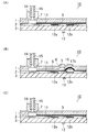
- FIG. 1 is a diagram showing an example of the configuration of a first target substance analysis chip according to the present invention.
- FIG. 1 (A) is a schematic perspective plan view
- FIG. 1 (B) is a diagram taken along II of FIG.
- FIG. 1C is a schematic cross-sectional view viewed from the direction II-II in FIG. 1A.
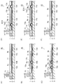
- FIG. 2 is a schematic cross-sectional view showing an example of a method of using the target substance analysis chip shown in FIG.
- FIG. 3 is a schematic cross-sectional view showing an example of the configuration of the second target substance analysis chip of the present invention.
- FIG. 4 is a schematic cross-sectional view showing an example of the configuration of the third target substance analysis chip of the present invention.
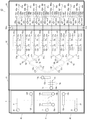
- FIG. 5 is a schematic perspective plan view showing another example of the configuration of the target substance analysis chip of the present invention.
- the target substance analysis chip of the present invention will be described with an example. Note that the present invention is not limited to these examples. In addition, the description in other embodiments can be incorporated in each embodiment unless otherwise indicated.
- FIG. 1 shows an example of the configuration of the first target substance analysis chip of the present invention.
- FIG. 1A is a schematic perspective plan view
- FIG. 1B is a schematic cross-sectional view seen from the II direction of FIG. 1A
- FIG. 1C is FIG. It is the schematic cross section seen from the II-II direction.
- the target substance analysis chip 10 has a laminated body in which a first flexible substrate 1, a second flexible substrate 2, and a third substrate 3 are laminated. In the stacked body, the stacking direction of the substrates is referred to as the vertical direction (hereinafter the same).
- a non-adhesive region for flow path 11 is formed in a band shape on the bonding surface between first flexible substrate 1 and second flexible substrate 2, and a band width is formed in part of non-adhesive region 11 for flow path. Is formed in the non-adhesive region 5 for the extraction chamber.
- the first flexible substrate 1 has a through hole 7 that is in contact with the non-adhesive region 11 for a flow path.
- the non-adhesion region for the extraction chamber is arranged on the adhesion surface between the second flexible substrate 2 and the third substrate 3 so as to vertically intersect the non-adhesion region 11 for the flow path via the second flexible substrate 2.
- non-bonding regions 12a and 12b for shutter are formed in a strip shape on the side closer to and farther from the through hole 7.
- the first flexible substrate 1 and the second flexible substrate 2 have pressure supply ports 18a and 18b penetrating so as to be in contact with the shutter non-adhesive regions 12a and 12b.
- the pressure supply ports 18a and 18b may be formed through the third substrate 3 so as to be in contact with the non-bonding regions 12a and 12b for shutter.
- magnetic particles that bind to the target substance are disposed on the upper part of the non-adhesion region 5 for the extraction chamber.
- the shutter non-adhesion region 12a and the pressure supply port 18a are optional components, and are preferably, but not necessary.
- the flow direction of the liquid in the formed flow path is the upstream side on the through hole 7 side along the non-adhesive region 11 for the flow path. Therefore, the shutter non-adhesion region 12a is formed downstream of the through-hole 7 and upstream of the extraction chamber non-adhesion region 5, that is, between the through-hole 7 and the extraction chamber non-adhesion region 5. In addition, it can be said that the shutter non-adhesion region 12b is formed on the downstream side of the extraction chamber non-adhesion region 5.
- one through hole 7 is provided at the left end of the non-adhesive region 11 for a flow path.
- the present invention is not limited to this.
- An appropriate number of the through holes may be provided at any position as long as the through holes are in contact with the non-adhesive region 11 for flow passage.
- one pressure supply port 18a and 18b is provided at each end of the shutter non-adhesive regions 12a and 12b.
- the present invention is not limited to this.
- An appropriate number of the pressure supply ports may be provided at any position as long as the pressure supply ports are in contact with the non-bonding region for the shutter.
- the shutter non-adhesive regions 12a and 12b and the flow channel non-adhesive region 11 only need to intersect with each other via the second flexible substrate 2, and the shape of the intersection is not particularly limited.
- the shutter non-adhesive regions 12a and 12b and the flow channel non-adhesive region 11 are orthogonal to each other, but are not limited thereto.
- the lower surface of the first flexible substrate 1 and the upper surface of the second flexible substrate 2 are bonded to each other around the non-bonding region 11 for the flow path, the through-hole 7 and the non-bonding region 5 for the extraction chamber, Preferably, they are bonded to each other at a portion other than the non-bonding region 11 for the flow path, the through hole 7 and the non-bonding region 5 for the extraction chamber.
- the lower surface of the second flexible substrate 2 and the upper surface of the third substrate 3 are bonded to each other at portions other than the shutter non-bonding regions 12a and 12b and the pressure supply ports 18a and 18b.
- the target substance analysis chip 10 can be manufactured, for example, as follows. First, the first flexible substrate 1, the second flexible substrate 2, and the third substrate 3 are prepared. The lower surface of the first flexible substrate 1, the upper and lower surfaces of the second flexible substrate 2, and the upper surface of the third substrate 3 are subjected to surface modification treatment for the purpose of increasing the adhesive strength between the substrates. May be.
- Examples of the surface modification treatment include oxygen plasma treatment, excimer UV light irradiation treatment, and the like.
- the oxygen plasma treatment can be performed using, for example, a reactive ion etching (RIE) apparatus in the presence of oxygen.
- RIE reactive ion etching
- the excimer UV light irradiation treatment can be performed in an air atmosphere at atmospheric pressure using, for example, a dielectric barrier discharge lamp.
- Examples of the material for forming the first flexible substrate 1 include silicone rubber such as polydimethylsiloxane (PDMS), nitrile rubber, hydrogenated nitrile rubber, fluorine rubber, ethylene propylene rubber, chloroprene rubber, acrylic rubber, butyl rubber, and urethane. Examples thereof include rubber, chlorosulfonated polyethylene rubber, epichlorohydrin rubber, natural rubber, isoprene rubber, styrene butadiene rubber, butadiene rubber, polysulfide rubber, norbornene rubber, and thermoplastic elastomer. These forming materials may be used alone or in combination of two or more. Among these, silicone rubber such as PDMS is particularly preferable.
- the thickness of the first flexible substrate 1 is, for example, in the range of 10 ⁇ m to 5 mm in consideration of strength and formation of a flow path and an extraction chamber described later.
- the formation method of the through-hole 7 and the pressure supply ports 18a and 18b in the first flexible substrate 1 is not particularly limited, and a conventionally known method may be used.
- the shapes of the through-hole 7 and the pressure supply ports 18a and 18b are not particularly limited, and may be any shape such as a cylindrical shape or a prism shape shown in FIG.
- the sizes of the through-hole 7 and the pressure supply ports 18a and 18b may be appropriately set according to, for example, the widths of a non-adhesion region for a flow path and a non-adhesion region for a shutter described later.
- Examples of the material for forming the second flexible substrate 2 include the same materials as those for forming the first flexible substrate 1.
- the material for forming the second flexible substrate 2 may be the same as or different from the material for forming the first flexible substrate 1, but the former is preferable.
- the conductive substrate 1 is silicone rubber
- the second flexible substrate 2 is also preferably silicone rubber. If both the first flexible substrate 1 and the second flexible substrate 2 are made of silicone rubber, they can be bonded by self-adsorption without using an adhesive.
- the thickness of the second flexible substrate 2 is, for example, in the range of 10 ⁇ m to 500 ⁇ m in view of strength and blockage of the flow path described later.
- the formation method of the pressure supply ports 18a and 18b to the second flexible substrate 2 is not particularly limited, and a conventionally known method may be used.
- the shape and size of the pressure supply ports 18a and 18b of the second flexible substrate 2 are the same as the shape and size of the pressure supply ports 18a and 18b of the first flexible substrate 1, for example.
- a non-adhesive region 11 for flow channels is formed in a strip shape on the upper surface of the second flexible substrate 2, and a non-adhesive region for an extraction chamber whose band width is widened in a part of the non-adhesive region 11 for flow channels 5 is formed.
- the non-adhesive region 11 for the flow path and the non-adhesive region 5 for the extraction chamber are formed by, for example, a conventionally known chemical thin film forming technique, for example, an electrode film, a dielectric protective film, a semiconductor film, a fluorescent film, a superconducting film, a dielectric Body film, solar cell film, antireflection film, antiwear film, optical interference film, reflection film, antistatic film, conductive film, antifouling film, hard coat film, barrier film, electromagnetic wave shielding film, infrared shielding film, ultraviolet ray It can be formed as an absorption film, a lubricating film, a shape memory film, a magnetic recording film, a light emitting element film, a biocompatible film, a corrosion resistant film, a catalyst film, a gas sensor film, or the like.
- a conventionally known chemical thin film forming technique for example, an electrode film, a dielectric protective film, a semiconductor film, a fluorescent film, a superconducting
- the above-described thin film can be formed by using, for example, an organic fluorine compound or a metal compound as a reactive gas by a plasma discharge treatment apparatus.
- organic fluorine compound examples include fluorinated methane, fluorinated ethane, tetrafluoromethane, hexafluoromethane, 1,1,2,2-tetrafluoroethylene, 1,1,1,2,3,3-hexa.
- Fluorocarbon compounds such as fluoropropane, hexafluoropropene and 6-fluoropropylene; 1,1-difluoroethylene, 1,1,1,2-tetrafluoroethane, 1,1,2,2,3-pentafluoro Fluorinated hydrocarbon compounds such as propane; Fluorocarbon compounds such as difluorodichloromethane and trifluorochloromethane; 1,1,1,3,3,3-hexafluoro-2-propanol, 1,3-difluoro-2- Fluorinated alcohols such as propanol and perfluorobutanol; vinyl trifluoroacetate, 1,1,1-trifluoro B acetate, etc. fluorinated carboxylic acid esters of; acetyl fluoride, hexafluoroacetone, 1,1,1-trifluoro fluoride ketones such as acetone: and the like.
- the metal compound examples include Al, As, Au, B, Bi, Ca, Cd, Cr, Co, Cu, Fe, Ga, Ge, Hg, In, Li, Mg, Mn, Mo, Na, Ni, Pb, Pt, Rh, Sb, Se, Si, Sn, Ti, V, W, Y, Zn, Zr or the like, or an alloy metal compound or an organometallic compound can be used.
- the aforementioned thin film can also be formed by a reactive ion etching system (RIE), a printing method, or the like in the presence of fluorocarbon (CHF 3 ) through a mask, for example.
- RIE reactive ion etching system
- the printing method for example, conventionally known printing methods such as roll printing, pattern printing, transfer, and electrostatic copying can be adopted.
- the forming material include metal fine particles, conductive ink, insulating ink, carbon fine particles, silane agent, parylene, paint, pigment, dye, water-based dye ink, water-based pigment ink, and oil-based material.
- the metal particles include, for example, Al, As, Au, B, Bi, Ca, Cd, Cr, Co, Cu, Fe, Ga, Ge, Hg, In, Li, Mg, Mn, Mo, Na, Ni, and Pb. , Pt, Rh, Sb, Se, Si, Sn, Ti, V, W, Y, Zn or Zr, etc., single metal fine particles, two or more kinds of these alloy fine particles, oxides of these single metals or alloys Examples thereof include fine particles (for example, ITO fine particles) and organic metal compound fine particles thereof.
- the thickness of the non-adhesion region 11 for the flow path and the non-adhesion region 5 for the extraction chamber is For example, it is in the range of 10 nm to 10 ⁇ m, and preferably in the range of 50 nm to 3 ⁇ m.
- the width of the non-adhesive region 11 for the flow channel is, for example, in the range of 10 ⁇ m to 3000 ⁇ m in consideration of the formation of the flow channel, which will be described later, and the supply amount of the target substance such as DNA and the reagent.
- Area for extraction chamber unbonded region 5 is formed of the extraction chamber to be described later, considering the supply amount of the target substance and the reagent, such as DNA, for example, in the range of 3 mm 2 ⁇ 300 mm 2, preferably, 16 mm 2 It is in the range of ⁇ 50 mm 2 .
- the shape of the non-adhesive region 11 for the flow path is not limited to the linear strip shown in FIG. 1, and various strip shapes such as a Y-shaped strip and an L-shaped strip can be employed.
- the shape of the non-adhesion region 5 for the extraction chamber is not limited to the circular shape shown in FIG. 1, and any shape such as a quadrangle can be adopted.
- Examples of the material for forming the third substrate 3 include silicone rubber such as acrylic and PDMS, glass, polyethylene terephthalate, polyethylene naphthalate, polyethylene, polypropylene, cellophane, cellulose diacetate, cellulose acetate butyrate, cellulose acetate propionate, Cellulose acetate phthalate, cellulose triacetate, cellulose nitrate, polyvinylidene chloride, polyvinyl alcohol, ethylene vinyl alcohol, polycarbonate, norbornene resin, polymethylpentene, polyether ketone, polyimide, polyether sulfone, polyether ketone imide, polyamide, fluorine resin , Nylon, polymethyl methacrylate, polyarylate, polylactic acid resin, polybutylene sac Nitrile rubber, hydrogenated nitrile rubber, fluorine rubber, ethylene propylene rubber, chloroprene rubber, acrylic rubber, butyl rubber, urethane rubber, chlorosulfonated polyethylene rubber, epich
- the surface of the third substrate 3 is preferably subjected to a surface treatment using a surface treatment agent for the purpose of improving the adhesion with the lower surface of the second flexible substrate 2 except in the non-adhesive region.
- a surface treatment agent include alkyl silanes such as dimethylsilane, tetramethylsilane, and tetraethylsilane; tetramethoxysilane, tetraethoxysilane, tetrapropoxysilane, dimethyldiethoxysilane, methyltrimethoxysilane, and ethyltriethoxysilane.
- non-bonding regions 12a and 12b for shutter are formed in a band shape.
- the shutter non-adhesive regions 12a and 12b may be formed to have the same thickness using, for example, the same forming material as the flow path non-adhesive region 11 and the extraction non-adhesive region 5.
- the width of the non-bonding regions 12a and 12b for the shutter is, for example, in the range of 10 ⁇ m to 5000 ⁇ m in consideration of the blockage of the flow path described later and economy.
- the first flexible substrate 1, the second flexible substrate 2, and the third substrate 3 are laminated.
- magnetic particles that bind to the target substance such as DNA are arranged on the upper part of the non-adhesion region 5 for the extraction chamber.
- “Coupling” may be, for example, direct coupling of the target substance to the magnetic particles or indirect coupling. In the former case, for example, adhesion to the magnetic particle itself is raised, and in the latter case, for example, the magnetic substance is adsorbed or adhered to a predetermined substance coated on the magnetic particle, or reacted by a reactive substance. Including the case of binding to body particles.
- the magnetic particles are preferably spherical, for example, and the particle diameter is preferably in the range of 0.3 ⁇ m to 5 ⁇ m, for example.
- the magnetic particles for example, a material having a porous surface or a mixture of at least one of silica gel and cellulose is suitable.
- the target substance analysis chip 10 shown in FIG. 1 can be obtained.
- the first target substance analysis method of the present invention can be performed using the first target substance analysis chip of the present invention.
- the first target substance analysis method uses, for example, the first target substance analysis chip of the present invention, and includes the following steps (a1) to (d1).
- A1 a step of forming a shutter portion that bulges the upper portion of the shutter non-adhesion region by closing the flow path by supplying pressure from the pressure supply port;
- B1 a step of raising the upper part of the non-adhesion region for the flow channel and the upper part of the non-adhesion region for the extraction chamber by supplying pressure from the through hole to form the flow channel and the extraction chamber;
- D1 A lower surface of the third substrate, a position immediately below an end of the extraction chamber opposite to the through hole side, and an upper surface of the first flexible substrate, the extraction chamber Generating a magnetic field at at least one position directly above the end opposite to the through-hole side in the step of
- the order of the steps is not particularly limited.
- the steps (a1) to (d1) may be performed in this order.
- the (a1) shutter portion forming step and the (b1) flow path and extraction chamber forming step may be performed first or simultaneously, for example.
- the analysis sample injection step (c1) may be performed simultaneously with the flow path and extraction chamber formation step (b1), for example.
- FIG. 2 As an example of a first target substance analysis method of the present invention, an example of a method of using the target substance analysis chip 10 shown in FIG. 1 will be described with reference to FIG.
- the form shown in FIG. 2 is an example, and the present invention is not limited to this form.
- an adapter 14 is installed at the opening of the through hole 7 serving as a liquid or gas introduction part, and an injection tube 15 is connected to the adapter 14.
- the shape of the adapter 14 is not limited to that shown in FIG.
- the adapter 14 may be in a form that is not directly inserted into the through hole 7 but directly fixed to the upper surface of the first flexible substrate 1.
- the injection tube 15 may be directly connected to the through hole 7 without using the adapter 14.
- silicone rubber such as PDMS is preferable, but other materials can also be used.
- an appropriate adhesive may be used to fix the adapter 14 to the upper surface of the first flexible substrate 1.
- An example of the injection tube 15 is a Teflon (registered trademark) tube.
- One end of the injection tube 15 is fixed to the adapter 14 using an appropriate adhesive.
- the other end of the injection tube 15 is connected to appropriate stock solution supply means, pressurization means (for example, a micropump, a syringe, etc.) and the like.
- the adapter 14 to which the injection tube 15 is connected is also installed in the pressure supply ports 18a and 18b. Then, gas is injected at a high pressure from the injection tube 15 through the pressure supply port 18b. As a result, as shown in FIG. 2B, the upper part of the shutter non-adhesion region 12b is raised, and the shutter gap 17b is formed. Specifically, only the portion of the first flexible substrate 1 and the second flexible substrate 2 that is positioned above the shutter non-adhesive region 12b is raised from the upper surface of the third substrate 3 and is used for the shutter. A gap 17b is generated.
- the shutter gap 17b formed by the protrusion is also referred to as a shutter portion (the same applies hereinafter).
- the gas is, for example, air or the like, and the degree of high pressure is, for example, in the range of 10 kPa to 300 kPa (hereinafter the same).
- the type of the analysis sample is not particularly limited, and can be appropriately selected according to, for example, the type of the target substance.
- the target substance include cells and intracellular components, and specific examples include nucleic acids such as DNA and RNA.
- the analysis sample may be, for example, a sample in which the target substance is eluted from cells, that is, an elution sample of cells (also referred to as target substance elution sample), or a cell It may be a sample from which the target substance is not eluted, that is, a sample containing cells. In the latter case, for example, the target substance analysis chip 10 may elute the target substance such as the nucleic acid from the cells in the analysis sample.
- the upper portion of the portion ahead of the shutter gap 17b that is, the upper portion on the downstream side of the shutter gap 17b in the non-bonding region 11 for the flow path is the shutter gap 17b. Therefore, no flow path is generated.
- the target substance contained in the injected analysis sample is bound to the magnetic particles 16.
- an elution reagent that elutes a target substance such as nucleic acid from the cell is applied to the target substance analysis chip 10 before, simultaneously with, or after injection of the analysis sample. It may be injected.
- the injection method is the same as that of the analysis sample, for example.
- the target substance eluted from the cells by the elution reagent is bound to the magnetic particles 16 in the extraction chamber 6.
- the elution reagent is previously disposed on the non-adhesion region 5 for the extraction chamber or on the non-adhesion region 11 for the flow path between the through hole 7 and the non-adhesion region 5 for the extraction chamber. You can also.
- a cleaning reagent is injected into the target substance analysis chip 10.
- the method for injecting the cleaning reagent is not particularly limited.
- the cleaning reagent is injected from the injection tube 15 through the through hole 7 by the same method as that for the analysis sample.
- a magnetic field is generated on the lower surface of the third substrate 3. Specifically, a magnetic field is generated on the lower surface of the third substrate 3 at a position directly below the end of the extraction chamber 6 opposite to the through hole 7 side. As a result, the target substance such as DNA bound to the magnetic particles 16 is captured in the extraction chamber 6. Thus, even if the flow path 8 is formed on the downstream side of the extraction chamber 6 by generating a magnetic field on the lower surface of the third substrate 3, the flow path 8 is formed downstream of the extraction chamber 6.
- the magnetic particles 16 can be prevented from flowing out.
- the magnetic field may be generated on the upper surface side of the first flexible substrate 1. Specifically, the magnetic field is on the upper surface side of the first flexible substrate 1 and on the through hole 7 side in the extraction chamber 6. May be generated just above the opposite end.
- the method of generating the magnetic field is not particularly limited, and examples thereof include a method of bringing a permanent magnet such as an alnico magnet, a ferrite magnet, a neodymium magnet, and a samarium cobalt magnet into contact with a magnet 13 such as an electromagnet.
- a permanent magnet such as an alnico magnet, a ferrite magnet, a neodymium magnet, and a samarium cobalt magnet into contact with a magnet 13 such as an electromagnet.
- the pressure of the gas injected from the through hole 7 and the pressure supply port 18b is set to about atmospheric pressure.
- the gaps of the flow path 8, the extraction chamber 6, and the shutter gap 17b are eliminated.
- gas is injected at a high pressure from the injection tube 15 through the through-hole 7.
- the cleaning reagent other than the target substance bonded to the magnetic particles 16 can be discharged from the flow path 8.
- the target substance analysis chip of this embodiment the target substance such as DNA can be efficiently extracted from the analysis sample by the magnetic particles 16 in this manner. Since the extraction of the target substance can be said to be the separation of the target substance from the analysis sample, the extraction chamber can be said to be a separation room for the target substance, for example.
- FIG. 3 shows an example of the configuration of the second target substance analysis chip of the present invention.
- the form shown in FIG. 3 is an example, and the present invention is not limited to this form. 3, the same parts as those in FIGS. 1 and 2 are denoted by the same reference numerals.
- the target substance analysis chip 10 shown in FIG. 3 is shown in FIGS. 1 and 2 except that the non-adhesion region 5 for the extraction chamber functions as the non-adhesion region 9 for the mixing chamber and does not include the magnetic particles 16.
- the target substance analysis chip 10 has the same configuration.
- the reagent and the analysis sample or the target substance in the analysis sample can be mixed in the mixing chamber 19 as follows.
- the reagent is not particularly limited, and can be appropriately selected depending on, for example, the type of the analysis sample, the type of the target substance, and the analysis method.
- the target substance is eluted from the cells as described above. Examples include an elution reagent, a reaction reagent that reacts with the target substance, and the washing reagent.
- the second target substance analysis method of the present invention can be performed using the second target substance analysis chip of the present invention.
- the second target substance analysis method uses, for example, the second target substance analysis chip of the present invention, and includes the following steps (a2) to (f2). (A2) By supplying pressure from the pressure supply port, an upper portion of the shutter non-adhesion area on the side farther from the through hole than the mixing chamber non-adhesion area is raised, and a shutter portion that closes the flow path is provided.
- Forming step, (B2) a step of raising the upper part of the non-adhesive region for the flow channel and the upper part of the non-adhesive region for the mixing chamber by supplying pressure from the through hole to form the flow channel and the mixing chamber; (C2) injecting an analysis sample into the flow path and the mixing chamber; (D2) injecting a reagent into the flow path and the mixing chamber; (E2) A shutter that blocks the flow path by raising the upper portion of the non-adhering region for the shutter closer to the through hole than the non-adhering region for the mixing chamber by supplying pressure from the pressure supply port. Forming a portion, and (F2) By applying pressure to the upper portion of the mixing chamber on the upper surface of the first flexible substrate to deform the mixing chamber, the target substance and the reagent in the analysis sample are changed in the mixing chamber.
- the order of the steps is not particularly limited.
- the steps (a2) to (f2) may be performed in this order.
- the shutter part forming step (a2) and the flow path and mixing chamber forming step (b2) may be performed first or simultaneously, for example.
- the analysis sample injection step (c2) and the reagent injection step (d2) may be performed first or simultaneously, for example.
- the analysis sample injection step (c2) and the sample injection step (d2) may be performed at the same time as the flow path and mixing chamber formation step (b2), for example.
- the analysis sample injection step (step before injection of the cleaning reagent) is performed in the same manner as in the first embodiment.
- the extraction chamber 6 is generated in the first embodiment, whereas the mixing chamber 19 is generated in the present embodiment.
- the various reagents described above may be injected into the target substance analysis chip 10, for example, before, simultaneously with, or after injection of the analysis sample.
- the injection method is the same as that of the analysis sample, for example.
- the analysis sample is a cell-containing sample as described above, for example, the elution reagent, the reaction reagent that reacts with the eluted target substance, and the washing reagent that cleans the target substance are injected as the reagent. May be.
- the analysis sample is a target substance elution sample as described above, for example, the reaction reagent, the washing reagent, and the like may be injected as the reagent.
- the elution reagent and the reaction reagent are, for example, arranged in advance on the non-adhesive region 9 for the mixing chamber or on the non-adhesive region 11 for the flow path between the through hole 7 and the non-adhesive region 9 for the mixing chamber. You can also keep it.
- gas is injected at high pressure from the injection tube 15 through the pressure supply port 18a.
- the upper part of the shutter non-adhesion region 12a is raised, and the shutter gap 17a is formed.
- the gas is, for example, air or the like, and the degree of high pressure is, for example, in the range of 10 kPa to 300 kPa (hereinafter the same).
- the pressure of the gas injected from the through hole 7 is set to about atmospheric pressure. As a result, as shown in FIG. 3C, the gap of the flow path 8 on the upstream side of the shutter gap 17a is eliminated.
- the mixing chamber 19 is deformed by applying pressure to the upper portion of the mixing chamber 19 on the upper surface of the first flexible substrate 1.
- the target substance and the reagent are mixed in the mixing chamber 19.
- the method for applying pressure to the position above the mixing chamber 19 is not particularly limited, and for example, high-pressure gas may be blown or an object may be pressed.
- the pressure of the gas injected from the pressure supply ports 18a and 18b is set to about atmospheric pressure.
- the gaps 17a and 17b for the shutter and the gap in the mixing chamber 19 are eliminated.
- gas is injected at a high pressure from the injection tube 15 through the through-hole 7.
- the target substance mixed with the reagent can be sent to the next step.
- magnetic particles similar to those of the first embodiment may be disposed in the non-adhesion region 9 for the mixing chamber.
- the mixing chamber 19 also functions as an extraction chamber.
- the third target substance analysis chip of the present invention is closer to the bonding surface between the second flexible substrate and the third substrate and closer to the through hole than the non-bonding region for the first mixing chamber.
- Two shutter non-adhesive regions are formed on the side and on the side farther from the through hole than the second mixing chamber non-adhesive region.
- the third target substance analysis chip further includes, for example, an adhesive surface between the second flexible substrate and the third substrate, and the non-adhesion region for the flow path via the second flexible substrate.
- the third shutter non-adhesive region may be formed in a strip shape so as to intersect vertically.
- the shutter non-adhesion region may be formed, for example, on the side farther from the through hole than the first mixing chamber non-adhesion region. In this case, the upstream and downstream flow paths of the first mixing chamber can be closed by the shutter portions, respectively.
- FIG. 4 shows an example of the configuration of the third target substance analysis chip of the present invention.
- the form shown in FIG. 4 is an example, and the present invention is not limited to this form. 4, the same parts as those in FIGS. 1 to 3 are denoted by the same reference numerals.
- the target substance analysis chip 10 shown in FIG. 4 has two non-adhesion areas for the mixing chamber (9a and 9b), four non-adhesion areas for the shutter (12a to 12d), and four pressure supply ports.
- the configuration is the same as that of the target substance analysis chip shown in FIG.
- the four pressure supply ports are referred to as pressure supply ports 18a to 18d for convenience.
- the shutter non-adhesive regions 12c and 12d are the first flexible substrate 1 and the second flexible substrate 2 in the same manner as the shutter non-adhesive regions 12a and 12b shown in FIG. Are in contact with the pressure supply ports 18c and 18d penetrating each other.
- the pressure supply ports 18c and 18d may be formed through the third substrate 3 so as to contact the non-bonding regions 12c and 12d for shutter.
- the shutter non-adhesive regions 12b and 12c and the pressure supply ports 18b and 18c are optional components, and are preferably, but not necessary.
- the shutter non-adhesion regions 12b and 12c and the pressure supply ports 18b and 18c may be combined into one, and the shutter non-adhesion region and the pressure supply port may be three.
- the third target substance analysis method of the present invention can be performed using the third target substance analysis chip of the present invention.
- the third target substance analysis method uses, for example, the third target substance analysis chip of the present invention, and includes the following steps (a3) to (f3). (A3) By supplying pressure from the through hole, the upper part of the non-adhesion region for the flow path, the upper part of the non-adhesion region for the first mixing chamber, and the upper part of the non-adhesion region for the second mixing chamber are raised.
- the order of the steps is not particularly limited, and can be performed, for example, in the order of the steps (a3) to (f3).
- the step (d3) may be performed before, simultaneously with, or after the step (a3), and is preferably performed before the steps (b3) and (c3).
- the step (e3) is preferably performed after the steps (b3) and (c3), for example.
- the formation of the first mixing chamber and the second mixing chamber in the step (a3) can be performed as separate steps, for example.
- the step (a3) may be the following step (a3-1) and the following step (a3-2).
- A3-1) By supplying pressure from the through hole, an upper portion of the non-adhesion region for the flow path between the through hole and the non-adhesion region for the first mixing chamber and the non-adhesion for the first mixing chamber Forming the flow path and the first mixing chamber by raising the upper portion of the bonding region (a3-2) by applying pressure to the upper portion of the first mixing chamber to deform the first mixing chamber;
- the upper portion of the non-adhesive region for the flow channel and the upper portion of the non-adhesive region for the second mixing chamber are raised between the non-adhesive region for the mixing chamber and the non-adhesive region for the second mixing chamber, and the flow channel and the second Process for forming the mixing chamber
- the formation step of the first mixing chamber (a3-1) is preferably performed before or simultaneously with the analysis sample injection step (b3) and the reagent injection step (c3).
- the step (a3-2) of forming the second mixing chamber may be performed, for example, before or after or during the step of forming the shutter part (d3) and (e3).
- the third target substance analysis chip has the third shutter non-adhesive region, prior to the formation of the first mixing chamber of (a3-1) or the analysis of (b3) Prior to the sample injection step and the reagent injection step (c3), the upper portion of the third non-adhesion region for the shutter may be raised to form a shutter portion.
- the target substance analysis chip 10 shown in FIG. 4 is used as follows, for example. First, as shown in FIG. 4A, the adapter 14 to which the injection tube 15 is connected is installed in each of the through hole 7 and the pressure supply ports 18a to 18d as in the first embodiment.
- gas is injected at a high pressure from the injection tube 15 through the pressure supply port 18b.
- the upper part of the shutter non-adhesion region 12b is raised, and the shutter gap 17b is formed.
- the portion of the first flexible substrate 1 and the second flexible substrate 2 that is positioned above the shutter non-adhesive region 12b is raised from the upper surface of the third substrate 3 and is used for the shutter.
- a gap 17b is generated.
- the gas is, for example, air or the like, and the degree of high pressure is, for example, in the range of 10 kPa to 300 kPa (hereinafter the same).
- the reagent is injected into the target substance analysis chip 10.
- the analysis sample is a cell-containing sample as described above and the elution reagent is used as the reagent, the target substance such as DNA is eluted from the cells in the first mixing chamber 19a.
- gas is injected at a high pressure from the injection tube 15 through the pressure supply port 18a.
- the upper portion of the shutter non-adhesion region 12a is raised, and the shutter gap 17a is formed.
- the gas is, for example, air or the like, and the degree of high pressure is, for example, in the range of 10 kPa to 300 kPa (hereinafter the same).
- the pressure of the gas injected from the through hole 7 is set to about atmospheric pressure. As a result, as shown in FIG. 4C, the gap of the flow path 8 on the upstream side of the shutter gap 17a is eliminated.
- the pressure of the gas injected from the pressure supply port 18b is set to about atmospheric pressure.
- the gap of the shutter gap 17b is eliminated.
- gas is injected at a high pressure from the injection tube 15 through the pressure supply port 18d.
- the upper part of the shutter non-adhesion region 12d is raised, and a shutter gap 17d is formed. Specifically, only the portion of the first flexible substrate 1 and the second flexible substrate 2 located above the shutter non-adhesion region 12d is raised from the upper surface of the third substrate 3, and the shutter A gap 17d is generated.
- a method for applying pressure to the upper portion of the first mixing chamber 19a and the upper portion of the second mixing chamber 19b is not particularly limited, and for example, high-pressure gas may be blown or an object may be pressed.
- the method of mixing the target substance and the reagent by reciprocating between the first mixing chamber 19a and the second mixing chamber 19b is alternately performed between the upper portion of the first mixing chamber 19a and the upper portion of the second mixing chamber 19b.
- the method is not limited to a method in which the first mixing chamber 19a and the second mixing chamber 19b are alternately deformed by applying pressure to the first mixing chamber 19a, and any method may be used.
- the target substance and the reagent are reciprocated and mixed between the first mixing chamber 19a and the second mixing chamber 19b. May be.
- the pressure of the gas injected from the through hole 7 and the pressure supply ports 18a and 18d is set to about atmospheric pressure.
- the flow path 8 As a result, as shown in FIG. 4F, the flow path 8, the shutter gaps 17a and 17d, and the gaps in the first mixing chamber 19a and the second mixing chamber 19b are eliminated.
- gas is injected at a high pressure from the injection tube 15 through the through-hole 7. Thereby, the target substance mixed with the reagent can be sent to the next step.
- magnetic particles similar to those in Embodiment 1 may be arranged in at least one of the first non-contact region 9a for the first mixing chamber and the non-contact region 9b for the second mixing chamber.
- at least one of the first mixing chamber 19a and the second mixing chamber 19b also functions as an extraction chamber.
- FIG. 5 shows another example of the configuration of the target substance analysis chip of the present invention.
- the form shown in FIG. 5 is an example, and the present invention is not limited to this form.
- the same parts as those in FIGS. 1 and 2 are denoted by the same reference numerals.
- the target substance analysis chip 20 shown in FIG. 5 has a configuration of the target substance analysis chip 10 shown in FIGS.
- the unit 50, the shutter non-contact region 12m, the pressure supply port 18m, and the electrophoresis analysis unit 60 are included as main components.
- the cleaning reagent supply unit 30, the PCR reaction reagent supply unit 40, the cleaning reagent collection unit 70, the PCR amplification unit 50, and the electrophoresis analysis unit 60 are made of the same material as the target substance analysis chip 10 shown in FIGS. 1 has a laminate in which a flexible substrate 1, a second flexible substrate 2 and a third substrate 3 are laminated.
- the shutter non-contact area 12m and the pressure supply port 18m can be formed in the same manner as the corresponding components of the target substance analysis chip 10 shown in FIGS.
- the cleaning reagent supply unit 30 includes a through-hole 37, a flow path non-adhesive region 31, a shutter non-adhesive region 12e, and a pressure supply port 18e as main components. These components can be formed in the same manner as the corresponding components of the target substance analysis chip 10 shown in FIGS.
- the non-adhesive region 31 for flow paths is in contact with the non-adhesive region 5 for the extraction chamber of the target substance analysis chip 10 shown in FIGS.
- the cleaning reagent supply unit 30 is an optional component and is preferably, but may not be present. When the cleaning reagent supply unit 30 is not provided, the cleaning reagent may be supplied from the through hole 7 of the target substance analysis chip 10 shown in FIGS.
- the PCR reaction reagent supply unit 40 includes a through hole 47, a flow path non-adhesive region 41, a shutter non-adhesive region 12f, and a pressure supply port 18f as main components. These components can be formed in the same manner as the corresponding components of the target substance analysis chip 10 shown in FIGS.
- the non-adhesive region 41 for flow paths is in contact with the non-adhesive region 5 for the extraction chamber of the target substance analysis chip 10 shown in FIGS.
- the PCR reagent supply unit 40 is an arbitrary component, and is preferably, but may not be present. When the PCR reagent supply unit 40 is not provided, the PCR reagent may be supplied from the through hole 7 of the target substance analysis chip 10 shown in FIGS.
- the cleaning reagent recovery unit 70 includes a flow path non-adhesive region 71, shutter non-adhesive regions 12n and 12o, pressure supply ports 18n and 18o, and a waste liquid tank 78 as main components.
- Components other than the waste liquid tank 78 can be formed in the same manner as the corresponding components of the target substance analysis chip 10 shown in FIGS.
- the waste liquid tank 78 can be formed in the same manner as the non-adhesion region 5 for the extraction chamber of the target substance analysis chip 10 shown in FIGS.
- the non-adhesion region 11 for the flow path continuing from the target substance analysis chip 10 shown in FIGS. 1 and 2 is 8 through the non-adhesion regions 12g to 12l for the shutter and the pressure supply ports 18g to 18l. It is divided into two non-adhesive areas 51a to 51h for flow paths.
- the division of the non-adhesive region for the flow path is not limited to eight, and can be appropriately increased or decreased depending on the desired analysis accuracy of the target substance.
- the shutter non-adhesion areas 12g to 12l, the pressure supply ports 18g to 18l, and the flow path non-adhesion areas 51a to 51h are formed in the same manner as the corresponding components of the target substance analysis chip 10 shown in FIGS. it can.
- the eight non-adhesive regions for flow paths 51a to 51h are in contact with the eight reaction vessels 52a to 52h, respectively.
- the non-adhesive regions for flow paths 51a to 51h are formed with non-adhesive regions for shutters 12p to 12z and 12 ⁇ to 12 ⁇ and pressure supply ports 18p to 18z and 18 ⁇ to 18 ⁇ , respectively, before and after contact with the reaction vessels 52a to 52h. Has been.
- the method for forming the reaction vessels 52a to 52h is not particularly limited, and for example, a conventionally known method for forming a PCR chip can be employed.
- the shutter non-adhesion regions 12p to 12z and 12 ⁇ to 12 ⁇ and the pressure supply ports 18p to 18z and 18 ⁇ to 18 ⁇ can be formed in the same manner as the corresponding components of the target substance analysis chip 10 shown in FIGS.
- At least one of the position directly below the reaction vessels 52a to 52h on the lower surface of the third substrate 3 and the position directly above the reaction vessels 52a to 52h on the upper surface of the first flexible substrate 1 is shown. Is provided with heating means such as a heater.
- the electrophoresis analysis unit 60 includes reagent tanks 67a to 67h, through holes 68a to 68h, flow path non-adhesive areas 61a to 61h and 62a to 62h, waste liquid tanks 65a to 65h and 66a to 66h, and electrodes 67i to 67p and 68i. -68p, 65i-65p and 66i-66p.
- Reagent tanks 67a to 67h are formed so as to be in contact with the flow path non-adhesion areas 51a to 51h of the PCR amplification unit 50 via the shutter non-contact area 12m and the pressure supply port 18m.
- the non-adhesive regions 61a to 61h for the flow path are formed so that one end thereof is in contact with the reagent tanks 67a to 67h and the other end is in contact with the waste liquid tanks 65a to 65h.
- the non-adhesive areas for flow passages 62a to 62h intersect with the non-adhesive areas for flow passages 61a to 61h, and have one end in contact with the through holes 68a to 68h and the other end in contact with the waste liquid tanks 66a to 66h. Yes.
- Electrodes 67i to 67p, 68i to 68p, 65i to 65p, and 66i to 66p are disposed in the reagent tanks 67a to 67h, the through holes 68a to 68h, and the waste liquid tanks 65a to 65h and 66a to 66h, respectively.
- a voltage can be applied to the electrodes 67i to 67p, 68i to 68p, 65i to 65p, and 66i to 66p from the upper part of the first flexible substrate 1 or the lower part of the third substrate 3.
- the through holes 67a to 67h and the non-adhesive areas 61a to 61h and 62a to 62h for the flow path can be formed in the same manner as the corresponding components of the target substance analysis chip 10 shown in FIGS.
- a groove may be formed in the third substrate 3 according to a conventionally known method, and this may be used as the flow path.
- the groove may have a width of about 100 ⁇ m and a depth of about 30 ⁇ m.
- the reagent tanks 67a to 67h and the waste liquid tanks 65a to 65h and 66a to 66h can be formed in the same manner as the non-adhesion region 5 for the extraction chamber of the target substance analysis chip 10 shown in FIGS.
- As the electrodes 67i to 67p, 68i to 68p, 65i to 65p, and 66i to 66p conventionally known ones can be used.
- an optical analysis means such as an absorbance measuring device is arranged.
- the target substance analysis chip 20 of the present embodiment is used for the mixing chamber shown in FIG. 3 or FIG. 4 in place of the configuration of the target substance analysis chip 10 having the non-contact region 5 for extraction chamber shown in FIGS.
- the configuration of the target substance analysis chip 10 having a non-contact region may be included.
- the target substance analysis chip 20 of the present embodiment further includes a through-hole for supplying dry air and a non-contact region for a flow path formed so as to be in contact with the non-contact region for the extraction chamber or the non-contact region for the mixing chamber. You may have.
- the size of the target substance analysis chip 20 of the present embodiment is, for example, in the range of 50 mm to 300 mm in length and in the range of 20 mm to 100 mm in width. As described above, the target substance analysis chip of the present invention is small in size, and therefore requires less installation space.
- the thickness of the target substance analysis chip 20 of the present embodiment is such that the mechanism for generating a magnetic field in the configuration of the target substance analysis chip 10 shown in FIGS. 1 and 2, the heating means in the PCR amplification unit 50, and the electrophoresis analysis unit 60. Excluding the optical analysis means and the like in the range of, for example, 0.5 mm to 5 mm. For this reason, the target substance analysis chip 20 of the present embodiment can be carried without being fixed in a predetermined space.
- the target substance analysis chip 20 shown in FIG. 5 is used as follows, for example. First, using the configuration of the target substance analysis chip 10 and the cleaning reagent supply unit 30 shown in FIGS. 1 and 2, the target substance such as DNA is extracted from the analysis sample in the same manner as in the first embodiment.
- the time required for extracting the target substance is, for example, about 5 minutes.
- the PCR reaction reagent is supplied from the PCR reaction reagent supply unit 40, and the target substance bonded to the magnetic particles is transferred to the cleaning reagent recovery unit 70.
- the cleaning reagent recovery unit 70 the product obtained by removing the cleaning reagent from the mixture of the target substance, the cleaning reagent, and the PCR reaction reagent is transferred to the PCR amplification unit 50.
- PCR amplification is performed by a conventionally known method such as adding a temperature cycle to the target substance and the PCR reaction reagent stored in the reaction vessels 52a to 52h.
- the time required for this PCR amplification is, for example, 10 minutes to 60 minutes, and preferably about 15 minutes.
- the amplification product of the target substance is transferred to the reagent tanks 67a to 67h of the electrophoresis analysis unit 60, and a voltage is applied to the electrodes 67i to 67p and 65i to 65p. A potential difference is generated between the waste liquid tanks 65a to 65h. As a result, the channel formed in the upper part of the channel non-adhesive regions 61a to 61h is filled with the amplification product of the target substance.
- an electrophoretic solution is supplied from the through holes 68a to 68h, and a voltage is applied to the electrodes 68i to 68p and 66i to 66p to generate a potential difference between the through holes 68a to 68h and the waste liquid tanks 66a to 66h.
- a small amount of the amplified substance of the target substance is introduced into the flow path formed in the upper part of the non-adhesive areas for flow passages 62a to 62h from the intersections of the non-adhesive areas for flow paths 61a to 61h and 62a to 62h.
- Perform electrophoresis analysis is, for example, about 5 minutes.
- Such an electrophoretic analysis method is conventionally known.
- target substance analysis chip 20 of the present embodiment extraction, amplification and analysis of a target substance such as DNA can be performed in a short time of about 20 minutes to about 70 minutes with little effort.
- the target substance analysis chip of this embodiment may be one that performs electrophoretic analysis without performing PCR amplification.
- the target substance analysis chip of this embodiment may analyze the target substance by a method other than electrophoretic analysis such as chemiluminescence, fluorescence, and enzyme coloration.
- the analysis of the target substance such as DNA may be performed by a conventionally known method such as an intercalator method or a method using a fluorescently labeled probe.
- the target substance analysis chip of the present invention is small and can analyze a target substance such as DNA in a short time and with little effort.
- the target substance analysis chip of the present invention is applicable to a wide range of uses including, for example, DNA analysis in criminal investigations.
Landscapes
- Chemical & Material Sciences (AREA)
- Health & Medical Sciences (AREA)
- Life Sciences & Earth Sciences (AREA)
- Chemical Kinetics & Catalysis (AREA)
- Analytical Chemistry (AREA)
- General Health & Medical Sciences (AREA)
- Molecular Biology (AREA)
- Physics & Mathematics (AREA)
- Dispersion Chemistry (AREA)
- Immunology (AREA)
- Biochemistry (AREA)
- Clinical Laboratory Science (AREA)
- Hematology (AREA)
- Pathology (AREA)
- Electrochemistry (AREA)
- General Physics & Mathematics (AREA)
- Organic Chemistry (AREA)
- Wood Science & Technology (AREA)
- Proteomics, Peptides & Aminoacids (AREA)
- Engineering & Computer Science (AREA)
- Zoology (AREA)
- Fluid Mechanics (AREA)
- Biophysics (AREA)
- Microbiology (AREA)
- Bioinformatics & Cheminformatics (AREA)
- General Engineering & Computer Science (AREA)
- Genetics & Genomics (AREA)
- Biotechnology (AREA)
- Automatic Analysis And Handling Materials Therefor (AREA)
- Apparatus Associated With Microorganisms And Enzymes (AREA)
- Measuring Or Testing Involving Enzymes Or Micro-Organisms (AREA)
Abstract
Description
第1可撓性基板、第2可撓性基板及び第3基板が積層された積層体を有し、
前記第1可撓性基板と前記第2可撓性基板との接着面に、流路用非接着領域が帯状に形成され、且つ、前記流路用非接着領域の一部に帯幅が広がった抽出室用非接着領域が形成されており、
前記第1可撓性基板は、前記流路用非接着領域と接する貫通孔を有し、
前記第2可撓性基板と前記第3基板との接着面に、シャッター用非接着領域が、前記第2可撓性基板を介して前記流路用非接着領域と上下で交差するように、前記抽出室用非接着領域より前記貫通孔から遠い側に帯状に形成されており、
前記第1可撓性基板と前記第2可撓性基板の両基板、及び前記第3基板の少なくとも一方は、前記シャッター用非接着領域と接するように貫通する圧力供給口を有し、
前記抽出室用非接着領域の上に、対象物質と結合する磁性体粒子が配置されており、
前記貫通孔から圧力を供給することにより、前記流路用非接着領域の上部及び前記抽出室用非接着領域の上部を隆起させて、流路及び抽出室を形成可能であり、
前記圧力供給口から圧力を供給することにより、前記シャッター用非接着領域の上部を隆起させて、前記流路を閉塞可能であり、
前記第3基板の下面であって、前記抽出室における前記貫通孔側とは反対側の端部の真下の位置、及び前記第1可撓性基板の上面であって、前記抽出室における前記貫通孔側とは反対側の端部の真上の位置の少なくとも一方の位置に、磁界を発生させ、前記磁性体粒子と結合した前記対象物質を捕捉可能とされている
ことを特徴とする。
第1可撓性基板、第2可撓性基板及び第3基板が積層された積層体を有し、
前記第1可撓性基板と前記第2可撓性基板との接着面に、流路用非接着領域が帯状に形成され、且つ、前記流路用非接着領域の一部に帯幅が広がった混合室用非接着領域が形成されており、
前記第1可撓性基板は、前記流路用非接着領域と接する貫通孔を有し、
前記第2可撓性基板と前記第3基板との接着面に、シャッター用非接着領域が、前記第2可撓性基板を介して前記流路用非接着領域と上下で交差するように、前記混合室用非接着領域より前記貫通孔に近い側及び遠い側に帯状(例えば、2本の帯状)に形成されており、
前記第1可撓性基板と前記第2可撓性基板の両基板、及び前記第3基板の少なくとも一方は、前記シャッター用非接着領域と接するように貫通する圧力供給口を有し、
前記貫通孔から圧力を供給することにより、前記流路用非接着領域の上部及び前記混合室用非接着領域の上部を隆起させて、流路及び混合室を形成可能であり、
前記圧力供給口から圧力を供給することにより、前記シャッター用非接着領域の上部を隆起させて、前記流路を閉塞可能であり、
前記第1可撓性基板の上面における前記混合室の上部に圧力をかけて前記混合室を変形させることにより、前記混合室内部において、対象物質及び試薬を混合可能とされている
ことを特徴とする。
第1可撓性基板、第2可撓性基板及び第3基板が積層された積層体を有し、
前記第1可撓性基板と前記第2可撓性基板との接着面に、流路用非接着領域が帯状に形成されており、
前記第1可撓性基板は、前記流路用非接着領域と接する貫通孔を有し、
前記第1可撓性基板と前記第2可撓性基板との接着面に、前記貫通孔側から、前記流路用非接着領域の一部に帯幅が広がった第1混合室用非接着領域及び第2混合室用非接着領域が、この順で形成されており、
前記第2可撓性基板と前記第3基板との接着面に、シャッター用非接着領域が、前記第2可撓性基板を介して前記流路用非接着領域と上下で交差するように、前記第1混合室用非接着領域より前記貫通孔に近い側及び前記第2混合室用非接着領域下部より前記貫通孔から遠い側に帯状(例えば、2本の帯状)に形成されており、
前記第1可撓性基板と前記第2可撓性基板の両基板、及び前記第3基板の少なくとも一方は、前記シャッター用非接着領域と接するように貫通する圧力供給口を有し、
前記貫通孔から圧力を供給することにより、前記流路用非接着領域の上部、前記第1混合室用非接着領域の上部及び前記第2混合室用非接着領域の上部を隆起させて、流路、第1混合室及び第2混合室を形成可能であり、
前記圧力供給口から圧力を供給することにより、前記シャッター用非接着領域の上部を隆起させて、前記流路を閉塞可能であり、
対象物質及び試薬を、前記第1混合室と前記第2混合室との間で往復させることにより混合可能とされている
ことを特徴とする。
図1に、本発明の第1の対象物質分析チップの構成の一例を示す。図1において、図1(A)が模式透視平面図、図1(B)が図1(A)のI-I方向から見た模式断面図、図1(C)が図1(A)のII-II方向から見た模式断面図である。図示のとおり、この対象物質分析チップ10は、第1可撓性基板1、第2可撓性基板2及び第3基板3が積層された積層体を有する。前記積層体において、各基板の積層方向を上下方向という(以下、同様)。第1可撓性基板1と第2可撓性基板2との接着面には、流路用非接着領域11が帯状に形成され、且つ、流路用非接着領域11の一部に帯幅が広がった抽出室用非接着領域5が形成されている。第1可撓性基板1は、流路用非接着領域11と接する貫通孔7を有する。第2可撓性基板2と第3基板3との接着面には、第2可撓性基板2を介して流路用非接着領域11と上下で交差するように、抽出室用非接着領域5より貫通孔7から近い側及び遠い側にシャッター用非接着領域12a及び12bが帯状に形成されている。第1可撓性基板1及び第2可撓性基板2は、シャッター用非接着領域12a及び12bと接するように貫通する圧力供給口18a及び18bを有する。圧力供給口18a及び18bは、第3基板3に、シャッター用非接着領域12a及び12bと接するように貫通させて形成されていてもよい。図示していないが、抽出室用非接着領域5の上部には、対象物質と結合する磁性体粒子が配置されている。本実施形態において、シャッター用非接着領域12a及び圧力供給口18aは、任意の構成要素であり、あることが好ましいが、なくてもよい。
(a1)前記圧力供給口から圧力を供給することにより、前記シャッター用非接着領域の上部を隆起させて、前記流路を閉塞するシャッター部を形成する工程、
(b1)前記貫通孔から圧力を供給することにより、前記流路用非接着領域の上部及び前記抽出室用非接着領域の上部を隆起させて、流路及び抽出室を形成する工程、
(c1)前記流路及び前記抽出室に分析サンプルを注入する工程、及び、
(d1)前記第3基板の下面であって、前記抽出室における前記貫通孔側とは反対側の端部の真下の位置、及び前記第1可撓性基板の上面であって、前記抽出室における前記貫通孔側とは反対側の端部の真上の位置の少なくとも一方の位置に、磁界を発生させ、前記磁性体粒子と結合した前記分析サンプル中の前記対象物質を捕捉する工程
図3に、本発明の第2の対象物質分析チップの構成の一例を示す。図3に示す形態は、一例であって、本発明は、この形態には制限されない。図3において、図1及び図2と同一部分には同一符号を付している。図3に示す対象物質分析チップ10は、抽出室用非接着領域5が混合室用非接着領域9として機能すること、及び、磁性体粒子16を含まないこと以外、図1及び図2に示した対象物質分析チップ10と同様の構成である。
(a2)前記圧力供給口から圧力を供給することにより、前記混合室用非接着領域より前記貫通孔に遠い側の前記シャッター用非接着領域の上部を隆起させ、流路を閉塞するシャッター部を形成する工程、
(b2)前記貫通孔から圧力を供給することにより、前記流路用非接着領域の上部及び前記混合室用非接着領域の上部を隆起させて、流路及び混合室を形成する工程、
(c2)前記流路及び前記混合室に分析サンプルを注入する工程、
(d2)前記流路及び前記混合室に試薬を注入する工程、
(e2)前記圧力供給口から圧力を供給することにより、前記混合室用非接着領域より前記貫通孔に近い側の前記シャッター用非接着領域の上部を隆起させて、前記流路を閉塞するシャッター部を形成する工程、及び、
(f2)前記第1可撓性基板の上面における前記混合室の上部に圧力をかけて前記混合室を変形させることにより、前記混合室内部において、前記分析サンプル中の前記対象物質及び前記試薬を混合する工程
本発明の第3の対象物質分析チップは、前述のように、前記第2可撓性基板と前記第3基板との接着面に、前記第1混合室用非接着領域より前記貫通孔に近い側及び前記第2混合室用非接着領域より前記貫通孔から遠い側に2本のシャッター用非接着領域が形成されている。前記第3の対象物質分析チップは、例えば、さらに、前記第2可撓性基板と前記第3基板との接着面に、前記第2可撓性基板を介して前記流路用非接着領域と上下で交差するように、3本目のシャッター用非接着領域が帯状に形成されてもよい。このシャッター用非接着領域は、例えば、前記第1混合室用非接着領域より前記貫通孔に遠い側に形成されてもよい。この場合、前記第1混合室の上流側と下流側の流路を、それぞれ、シャッター部によって閉塞できる。
(a3)前記貫通孔から圧力を供給することにより、前記流路用非接着領域の上部、前記第1混合室用非接着領域の上部及び前記第2混合室用非接着領域の上部を隆起させて、流路、第1混合室及び第2混合室を形成する工程、
(b3)前記流路及び前記混合室に分析サンプルを注入する工程、
(c3)前記流路及び前記混合室に試薬を注入する工程、
(d3)前記圧力供給口から圧力を供給することにより、前記第1混合室用非接着領域より前記貫通孔に近い側の前記シャッター用非接着領域の上部を隆起させて、前記流路を閉塞するシャッター部を形成する工程、
(e3)前記圧力供給口から圧力を供給することにより、前記第2混合室用非接着領域より前記貫通孔に遠い側の前記シャッター用非接着領域の上部を隆起させて、前記流路を閉塞するシャッター部を形成する工程、及び、
(f3)前記分析サンプル中の対象物質及び前記試薬を、前記第1混合室と前記第2混合室との間で往復させることにより混合する工程
(a3-1)前記貫通孔から圧力を供給することにより、前記貫通孔と前記第1混合室用非接着領域との間における前記流路用非接着領域の上部及び前記第1混合室用非接着領域の上部を隆起させて、流路及び第1混合室を形成する工程
(a3-2)前記第1混合室の上部に圧力をかけて前記第1混合室を変形させることにより、前記1混合室用非接着領域と前記第2混合室用非接着領域の間における前記流路用非接着領域の上部及び前記第2混合室用非接着領域の上部を隆起させて、流路及び第2混合室を形成する工程
図5に、本発明の対象物質分析チップの構成のその他の例を示す。図5に示す形態は、一例であって、本発明は、この形態には制限されない。図5において、図1及び図2と同一部分には同一符号を付している。図5に示す対象物質分析チップ20は、図1及び図2に示した対象物質分析チップ10の構成に加え、洗浄試薬供給部30、PCR反応試薬供給部40、洗浄試薬回収部70、PCR増幅部50、シャッター用非接触領域12m、圧力供給口18m及び電気泳動解析部60を、主要な構成要素として含む。洗浄試薬供給部30、PCR反応試薬供給部40、洗浄試薬回収部70、PCR増幅部50及び電気泳動解析部60は、図1及び図2に示した対象物質分析チップ10と同様の素材の第1可撓性基板1、第2可撓性基板2及び第3基板3が積層された積層体を有する。シャッター用非接触領域12m及び圧力供給口18mは、図1及び図2に示した対象物質分析チップ10の対応する構成要素と同様にして形成できる。
2 第2可撓性基板
3 第3基板
5 抽出室用非接着領域
6 抽出室
7、37、47、68a~68h 貫通孔
8 流路
9 混合室用非接着領域
10、20 対象物質分析チップ
11、31、41、51a~51h、61a~61h、62a~62h、71 流路用非接着領域
12a~12z、12α~12ε シャッター用非接着領域
13 磁石
14 アダプター
15 注入チューブ
16 磁性体粒子
17a、17b、17d シャッター用空隙
18a~18z、18α~18ε 圧力供給口
19 混合室
30 洗浄試薬供給部
40 PCR反応試薬供給部
50 PCR増幅部
60 電気泳動解析部
65a~65h、66a~66h、78 廃液槽
70 洗浄試薬回収部
Claims (8)
- 第1可撓性基板、第2可撓性基板及び第3基板が積層された積層体を有し、
前記第1可撓性基板と前記第2可撓性基板との接着面に、流路用非接着領域が帯状に形成され、且つ、前記流路用非接着領域の一部に帯幅が広がった抽出室用非接着領域が形成されており、
前記第1可撓性基板は、前記流路用非接着領域と接する貫通孔を有し、
前記第2可撓性基板と前記第3基板との接着面に、シャッター用非接着領域が、前記第2可撓性基板を介して前記流路用非接着領域と上下で交差するように、前記抽出室用非接着領域より前記貫通孔から遠い側に帯状に形成されており、
前記第1可撓性基板と前記第2可撓性基板の両基板、及び前記第3基板の少なくとも一方は、前記シャッター用非接着領域と接するように貫通する圧力供給口を有し、
前記抽出室用非接着領域の上に、対象物質と結合する磁性体粒子が配置されており、
前記貫通孔から圧力を供給することにより、前記流路用非接着領域の上部及び前記抽出室用非接着領域の上部を隆起させて、流路及び抽出室を形成可能であり、
前記圧力供給口から圧力を供給することにより、前記シャッター用非接着領域の上部を隆起させて、前記流路を閉塞可能であり、
前記第3基板の下面であって、前記抽出室における前記貫通孔側とは反対側の端部の真下の位置、及び前記第1可撓性基板の上面であって、前記抽出室における前記貫通孔側とは反対側の端部の真上の位置の少なくとも一方の位置に、磁界を発生させ、前記磁性体粒子と結合した前記対象物質を捕捉可能とされている
ことを特徴とする対象物質分析チップ。 - 第1可撓性基板、第2可撓性基板及び第3基板が積層された積層体を有し、
前記第1可撓性基板と前記第2可撓性基板との接着面に、流路用非接着領域が帯状に形成され、且つ、前記流路用非接着領域の一部に帯幅が広がった混合室用非接着領域が形成されており、
前記第1可撓性基板は、前記流路用非接着領域と接する貫通孔を有し、
前記第2可撓性基板と前記第3基板との接着面に、シャッター用非接着領域が、前記第2可撓性基板を介して前記流路用非接着領域と上下で交差するように、前記混合室用非接着領域より前記貫通孔に近い側及び遠い側に帯状に形成されており、
前記第1可撓性基板と前記第2可撓性基板の両基板、及び前記第3基板の少なくとも一方は、前記シャッター用非接着領域と接するように貫通する圧力供給口を有し、
前記貫通孔から圧力を供給することにより、前記流路用非接着領域の上部及び前記混合室用非接着領域の上部を隆起させて、流路及び混合室を形成可能であり、
前記圧力供給口から圧力を供給することにより、前記シャッター用非接着領域の上部を隆起させて、前記流路を閉塞可能であり、
前記第1可撓性基板の上面における前記混合室の上部に圧力をかけて前記混合室を変形させることにより、前記混合室内部において、対象物質及び試薬を混合可能とされている
ことを特徴とする対象物質分析チップ。 - 第1可撓性基板、第2可撓性基板及び第3基板が積層された積層体を有し、
前記第1可撓性基板と前記第2可撓性基板との接着面に、流路用非接着領域が帯状に形成されており、
前記第1可撓性基板は、前記流路用非接着領域と接する貫通孔を有し、
前記第1可撓性基板と前記第2可撓性基板との接着面に、前記貫通孔側から、前記流路用非接着領域の一部に帯幅が広がった第1混合室用非接着領域及び第2混合室用非接着領域が、この順で形成されており、
前記第2可撓性基板と前記第3基板との接着面に、シャッター用非接着領域が、前記第2可撓性基板を介して前記流路用非接着領域と上下で交差するように、前記第1混合室用非接着領域より前記貫通孔に近い側及び前記第2混合室用非接着領域より前記貫通孔から遠い側に帯状に形成されており、
前記第1可撓性基板と前記第2可撓性基板の両基板、及び前記第3基板の少なくとも一方は、前記シャッター用非接着領域と接するように貫通する圧力供給口を有し、
前記貫通孔から圧力を供給することにより、前記流路用非接着領域の上部、前記第1混合室用非接着領域の上部及び前記第2混合室用非接着領域の上部を隆起させて、流路、第1混合室及び第2混合室を形成可能であり、
前記圧力供給口から圧力を供給することにより、前記シャッター用非接着領域の上部を隆起させて、前記流路を閉塞可能であり、
対象物質及び試薬を、前記第1混合室と前記第2混合室との間で往復させることにより混合可能とされている
ことを特徴とする対象物質分析チップ。 - さらに、前記第2可撓性基板と前記第3基板との接着面に、シャッター用非接着領域が、前記第2可撓性基板を介して前記流路用非接着領域と上下で交差するように、前記第1混合室用非接着領域より前記貫通孔に遠い側に帯状に形成されている、
ことを特徴とする請求項3記載の対象物質分析チップ。 - さらに、増幅部を含む
ことを特徴とする請求項1から4のいずれか一項に記載の対象物質分析チップ。 - 前記増幅部が、PCR増幅部を含む
ことを特徴とする請求項5記載の対象物質分析チップ。 - さらに、解析部を含む
ことを特徴とする請求項1から6のいずれか一項に記載の対象物質分析チップ。 - 前記解析部が、電気泳動解析部を含む
ことを特徴とする請求項7記載の対象物質分析チップ。
Priority Applications (4)
| Application Number | Priority Date | Filing Date | Title |
|---|---|---|---|
| US14/386,527 US20150050721A1 (en) | 2012-03-21 | 2013-01-23 | Chip for analysis of target substance |
| EP13764529.7A EP2829882B8 (en) | 2012-03-21 | 2013-01-23 | Chip for analysis of target substance |
| DK13764529.7T DK2829882T3 (da) | 2012-03-21 | 2013-01-23 | Chip til analyse af en målsubstans |
| US15/130,601 US9885077B2 (en) | 2012-03-21 | 2016-04-15 | Chip for analysis of target substance |
Applications Claiming Priority (2)
| Application Number | Priority Date | Filing Date | Title |
|---|---|---|---|
| JP2012063645 | 2012-03-21 | ||
| JP2012-063645 | 2012-03-21 |
Related Child Applications (2)
| Application Number | Title | Priority Date | Filing Date |
|---|---|---|---|
| US14/386,527 A-371-Of-International US20150050721A1 (en) | 2012-03-21 | 2013-01-23 | Chip for analysis of target substance |
| US15/130,601 Continuation US9885077B2 (en) | 2012-03-21 | 2016-04-15 | Chip for analysis of target substance |
Publications (1)
| Publication Number | Publication Date |
|---|---|
| WO2013140846A1 true WO2013140846A1 (ja) | 2013-09-26 |
Family
ID=49222314
Family Applications (1)
| Application Number | Title | Priority Date | Filing Date |
|---|---|---|---|
| PCT/JP2013/051332 WO2013140846A1 (ja) | 2012-03-21 | 2013-01-23 | 対象物質分析チップ |
Country Status (5)
| Country | Link |
|---|---|
| US (2) | US20150050721A1 (ja) |
| EP (1) | EP2829882B8 (ja) |
| JP (2) | JPWO2013140846A1 (ja) |
| DK (1) | DK2829882T3 (ja) |
| WO (1) | WO2013140846A1 (ja) |
Cited By (3)
| Publication number | Priority date | Publication date | Assignee | Title |
|---|---|---|---|---|
| WO2017046836A1 (ja) * | 2015-09-14 | 2017-03-23 | 株式会社日立製作所 | 化学分析装置 |
| EP3096882A4 (en) * | 2014-01-24 | 2017-09-20 | The Johns Hopkins University | System and device for high throughput generation of combinatorial droplets and methods of use |
| JP2018534538A (ja) * | 2015-09-04 | 2018-11-22 | ライフ テクノロジーズ コーポレーション | メソ流体および/またはマイクロ流体プロセス用のデバイスおよび方法 |
Families Citing this family (7)
| Publication number | Priority date | Publication date | Assignee | Title |
|---|---|---|---|---|
| ES2608930T3 (es) | 2012-01-04 | 2017-04-17 | Magnomics, S.A. | Dispositivo monolítico que combina CMOS con sensores magnetorresistivos |
| CN110560187B (zh) * | 2013-11-18 | 2022-01-11 | 尹特根埃克斯有限公司 | 用于样本分析的卡盒和仪器 |
| JP6803561B2 (ja) * | 2017-01-23 | 2020-12-23 | パナソニックIpマネジメント株式会社 | マイクロ流路での検体と反応試薬との混合方法 |
| WO2019146102A1 (ja) * | 2018-01-29 | 2019-08-01 | 株式会社ニコン | 流体デバイス及びその使用 |
| WO2019146104A1 (ja) * | 2018-01-29 | 2019-08-01 | 株式会社ニコン | 流体デバイス及びシステム |
| CN109603942B (zh) * | 2019-02-15 | 2021-12-24 | 京东方科技集团股份有限公司 | 微流控装置和微流控方法 |
| CN110854136B (zh) * | 2019-10-31 | 2022-04-12 | 深圳市华星光电半导体显示技术有限公司 | 柔性显示装置基板及其制备方法 |
Citations (5)
| Publication number | Priority date | Publication date | Assignee | Title |
|---|---|---|---|---|
| WO2009035061A1 (ja) * | 2007-09-10 | 2009-03-19 | Nec Corporation | マイクロチップの試料処理装置 |
| WO2009038203A1 (ja) * | 2007-09-21 | 2009-03-26 | Nec Corporation | 温度制御方法及びシステム |
| JP2009247297A (ja) | 2008-04-08 | 2009-10-29 | Hitachi Ltd | Dna分析装置 |
| JP2011237277A (ja) * | 2010-05-11 | 2011-11-24 | Hitachi High-Technologies Corp | 核酸分析反応セルおよび核酸分析装置 |
| JP2011242234A (ja) * | 2010-05-18 | 2011-12-01 | Yokogawa Electric Corp | 化学処理用カートリッジ |
Family Cites Families (13)
| Publication number | Priority date | Publication date | Assignee | Title |
|---|---|---|---|---|
| US20020022261A1 (en) * | 1995-06-29 | 2002-02-21 | Anderson Rolfe C. | Miniaturized genetic analysis systems and methods |
| WO2003085379A2 (en) * | 2002-04-01 | 2003-10-16 | Fluidigm Corporation | Microfluidic particle-analysis systems |
| JP4464158B2 (ja) * | 2004-02-13 | 2010-05-19 | キヤノン株式会社 | 生化学反応カートリッジ |
| US7763453B2 (en) * | 2005-11-30 | 2010-07-27 | Micronics, Inc. | Microfluidic mixing and analytic apparatus |
| US8147774B2 (en) * | 2006-07-05 | 2012-04-03 | Aida Engineering, Ltd. | Micro passage chip and fluid transferring method |
| CN103418295B (zh) * | 2007-06-21 | 2015-11-18 | 简.探针公司 | 用于混合检测腔室的内容物的仪器和方法 |
| JP2009210327A (ja) * | 2008-03-03 | 2009-09-17 | Yokogawa Electric Corp | 化学反応用カートリッジ、混合物生成方法及び化学反応用カートリッジの制御装置 |
| WO2009119698A1 (ja) * | 2008-03-24 | 2009-10-01 | 日本電気株式会社 | マイクロチップの流路制御機構 |
| JP2010145269A (ja) | 2008-12-19 | 2010-07-01 | Yokogawa Electric Corp | 化学処理用カートリッジの使用方法 |
| CN102803147B (zh) * | 2009-06-05 | 2015-11-25 | 尹特根埃克斯有限公司 | 通用样品准备系统以及在一体化分析系统中的用途 |
| TWI421495B (zh) * | 2009-10-30 | 2014-01-01 | Univ Nat Cheng Kung | 微流體晶片 |
| US8396888B2 (en) | 2009-12-04 | 2013-03-12 | Google Inc. | Location-based searching using a search area that corresponds to a geographical location of a computing device |
| US9995742B2 (en) * | 2012-12-19 | 2018-06-12 | Dnae Group Holdings Limited | Sample entry |
-
2013
- 2013-01-23 DK DK13764529.7T patent/DK2829882T3/da active
- 2013-01-23 WO PCT/JP2013/051332 patent/WO2013140846A1/ja active Application Filing
- 2013-01-23 US US14/386,527 patent/US20150050721A1/en not_active Abandoned
- 2013-01-23 EP EP13764529.7A patent/EP2829882B8/en active Active
- 2013-01-23 JP JP2014506059A patent/JPWO2013140846A1/ja active Pending
-
2016
- 2016-04-15 US US15/130,601 patent/US9885077B2/en active Active
- 2016-06-30 JP JP2016130157A patent/JP2016200599A/ja active Pending
Patent Citations (5)
| Publication number | Priority date | Publication date | Assignee | Title |
|---|---|---|---|---|
| WO2009035061A1 (ja) * | 2007-09-10 | 2009-03-19 | Nec Corporation | マイクロチップの試料処理装置 |
| WO2009038203A1 (ja) * | 2007-09-21 | 2009-03-26 | Nec Corporation | 温度制御方法及びシステム |
| JP2009247297A (ja) | 2008-04-08 | 2009-10-29 | Hitachi Ltd | Dna分析装置 |
| JP2011237277A (ja) * | 2010-05-11 | 2011-11-24 | Hitachi High-Technologies Corp | 核酸分析反応セルおよび核酸分析装置 |
| JP2011242234A (ja) * | 2010-05-18 | 2011-12-01 | Yokogawa Electric Corp | 化学処理用カートリッジ |
Non-Patent Citations (1)
| Title |
|---|
| See also references of EP2829882A4 |
Cited By (5)
| Publication number | Priority date | Publication date | Assignee | Title |
|---|---|---|---|---|
| EP3096882A4 (en) * | 2014-01-24 | 2017-09-20 | The Johns Hopkins University | System and device for high throughput generation of combinatorial droplets and methods of use |
| US10406520B2 (en) | 2014-01-24 | 2019-09-10 | The Johns Hopkins University | System and device for high throughput generation of combinatorial droplets and methods of use |
| JP2018534538A (ja) * | 2015-09-04 | 2018-11-22 | ライフ テクノロジーズ コーポレーション | メソ流体および/またはマイクロ流体プロセス用のデバイスおよび方法 |
| WO2017046836A1 (ja) * | 2015-09-14 | 2017-03-23 | 株式会社日立製作所 | 化学分析装置 |
| JPWO2017046836A1 (ja) * | 2015-09-14 | 2018-03-29 | 株式会社日立製作所 | 化学分析装置 |
Also Published As
| Publication number | Publication date |
|---|---|
| EP2829882B1 (en) | 2020-02-19 |
| DK2829882T3 (da) | 2020-05-18 |
| EP2829882A1 (en) | 2015-01-28 |
| EP2829882B8 (en) | 2020-04-01 |
| US20150050721A1 (en) | 2015-02-19 |
| US9885077B2 (en) | 2018-02-06 |
| EP2829882A4 (en) | 2015-12-02 |
| JPWO2013140846A1 (ja) | 2015-08-03 |
| JP2016200599A (ja) | 2016-12-01 |
| US20170022539A1 (en) | 2017-01-26 |
Similar Documents
| Publication | Publication Date | Title |
|---|---|---|
| WO2013140846A1 (ja) | 対象物質分析チップ | |
| US9459186B2 (en) | Sample preparation and loading module | |
| US6919046B2 (en) | Microfluidic analytical devices and methods | |
| JP4721227B2 (ja) | マイクロ流路チップ及びその製造方法 | |
| Kirby et al. | Programmable modification of cell adhesion and zeta potential in silica microchips | |
| US8574923B2 (en) | Sample preparation device | |
| EP2217344B1 (en) | Method for purifying a nucleic acid from a sample | |
| US6939452B2 (en) | Parallel sample loading and injection device for multichannel microfluidic devices | |
| WO2016011134A1 (en) | Microfluidics cartridge with pipetting guide | |
| WO2008004572A1 (fr) | Puce à micro passage et procédé de transfert de fluide | |
| ITBO20090155A1 (it) | Metodo per l'isolamento di particelle | |
| WO2018232167A1 (en) | Nucleic acid extraction and purification cartridges | |
| EP2902104A1 (en) | Functional device and functional device manufacturing method | |
| JPWO2009034819A1 (ja) | マイクロチップの製造方法、マイクロチップ、真空貼付装置 | |
| EP2485039B1 (en) | Micro-channel chip and micro-analysis system | |
| EP4036586A1 (en) | Container and inspection kit | |
| CN113677425A (zh) | 微流体装置和用于提供乳液液滴的方法 | |
| ITBO20090154A1 (it) | Sistema microfluidico | |
| JP4366523B2 (ja) | 電気泳動用チップ及びこれを用いた試料の分析方法 | |
| US20210116338A1 (en) | Fluidic bead trap and methods of use | |
| JP2007113520A (ja) | 流路内蔵基板および流路制御装置ならびに流路制御方法 | |
| EP4220185A1 (en) | Inspection chip | |
| JP2004279202A (ja) | 分析用チップ及び分析装置並びに分析方法 | |
| CN110465337B (zh) | 芯片及其液流控制方法和应用 | |
| JP2014081329A (ja) | 核酸分析カートリッジ |
Legal Events
| Date | Code | Title | Description |
|---|---|---|---|
| 121 | Ep: the epo has been informed by wipo that ep was designated in this application |
Ref document number: 13764529 Country of ref document: EP Kind code of ref document: A1 |
|
| ENP | Entry into the national phase |
Ref document number: 2014506059 Country of ref document: JP Kind code of ref document: A |
|
| WWE | Wipo information: entry into national phase |
Ref document number: 2013764529 Country of ref document: EP |
|
| WWE | Wipo information: entry into national phase |
Ref document number: 14386527 Country of ref document: US |
|
| NENP | Non-entry into the national phase |
Ref country code: DE |