WO2013137352A1 - 流体機械 - Google Patents
流体機械 Download PDFInfo
- Publication number
- WO2013137352A1 WO2013137352A1 PCT/JP2013/057084 JP2013057084W WO2013137352A1 WO 2013137352 A1 WO2013137352 A1 WO 2013137352A1 JP 2013057084 W JP2013057084 W JP 2013057084W WO 2013137352 A1 WO2013137352 A1 WO 2013137352A1
- Authority
- WO
- WIPO (PCT)
- Prior art keywords
- bypass
- suction port
- expander
- fluid machine
- working fluid
- Prior art date
- Legal status (The legal status is an assumption and is not a legal conclusion. Google has not performed a legal analysis and makes no representation as to the accuracy of the status listed.)
- Ceased
Links
Images


Classifications
-
- F—MECHANICAL ENGINEERING; LIGHTING; HEATING; WEAPONS; BLASTING
- F01—MACHINES OR ENGINES IN GENERAL; ENGINE PLANTS IN GENERAL; STEAM ENGINES
- F01K—STEAM ENGINE PLANTS; STEAM ACCUMULATORS; ENGINE PLANTS NOT OTHERWISE PROVIDED FOR; ENGINES USING SPECIAL WORKING FLUIDS OR CYCLES
- F01K23/00—Plants characterised by more than one engine delivering power external to the plant, the engines being driven by different fluids
- F01K23/02—Plants characterised by more than one engine delivering power external to the plant, the engines being driven by different fluids the engine cycles being thermally coupled
- F01K23/06—Plants characterised by more than one engine delivering power external to the plant, the engines being driven by different fluids the engine cycles being thermally coupled combustion heat from one cycle heating the fluid in another cycle
- F01K23/065—Plants characterised by more than one engine delivering power external to the plant, the engines being driven by different fluids the engine cycles being thermally coupled combustion heat from one cycle heating the fluid in another cycle the combustion taking place in an internal combustion piston engine, e.g. a diesel engine
-
- F—MECHANICAL ENGINEERING; LIGHTING; HEATING; WEAPONS; BLASTING
- F01—MACHINES OR ENGINES IN GENERAL; ENGINE PLANTS IN GENERAL; STEAM ENGINES
- F01C—ROTARY-PISTON OR OSCILLATING-PISTON MACHINES OR ENGINES
- F01C1/00—Rotary-piston machines or engines
- F01C1/02—Rotary-piston machines or engines of arcuate-engagement type, i.e. with circular translatory movement of co-operating members, each member having the same number of teeth or tooth-equivalents
- F01C1/0207—Rotary-piston machines or engines of arcuate-engagement type, i.e. with circular translatory movement of co-operating members, each member having the same number of teeth or tooth-equivalents both members having co-operating elements in spiral form
- F01C1/0215—Rotary-piston machines or engines of arcuate-engagement type, i.e. with circular translatory movement of co-operating members, each member having the same number of teeth or tooth-equivalents both members having co-operating elements in spiral form where only one member is moving
-
- F—MECHANICAL ENGINEERING; LIGHTING; HEATING; WEAPONS; BLASTING
- F01—MACHINES OR ENGINES IN GENERAL; ENGINE PLANTS IN GENERAL; STEAM ENGINES
- F01C—ROTARY-PISTON OR OSCILLATING-PISTON MACHINES OR ENGINES
- F01C20/00—Control of, monitoring of, or safety arrangements for, machines or engines
- F01C20/24—Control of, monitoring of, or safety arrangements for, machines or engines characterised by using valves for controlling pressure or flow rate, e.g. discharge valves
- F01C20/26—Control of, monitoring of, or safety arrangements for, machines or engines characterised by using valves for controlling pressure or flow rate, e.g. discharge valves using bypass channels
-
- F—MECHANICAL ENGINEERING; LIGHTING; HEATING; WEAPONS; BLASTING
- F01—MACHINES OR ENGINES IN GENERAL; ENGINE PLANTS IN GENERAL; STEAM ENGINES
- F01K—STEAM ENGINE PLANTS; STEAM ACCUMULATORS; ENGINE PLANTS NOT OTHERWISE PROVIDED FOR; ENGINES USING SPECIAL WORKING FLUIDS OR CYCLES
- F01K13/00—General layout or general methods of operation of complete plants
- F01K13/02—Controlling, e.g. stopping or starting
-
- F—MECHANICAL ENGINEERING; LIGHTING; HEATING; WEAPONS; BLASTING
- F01—MACHINES OR ENGINES IN GENERAL; ENGINE PLANTS IN GENERAL; STEAM ENGINES
- F01K—STEAM ENGINE PLANTS; STEAM ACCUMULATORS; ENGINE PLANTS NOT OTHERWISE PROVIDED FOR; ENGINES USING SPECIAL WORKING FLUIDS OR CYCLES
- F01K15/00—Adaptations of plants for special use
- F01K15/02—Adaptations of plants for special use for driving vehicles, e.g. locomotives
-
- F—MECHANICAL ENGINEERING; LIGHTING; HEATING; WEAPONS; BLASTING
- F02—COMBUSTION ENGINES; HOT-GAS OR COMBUSTION-PRODUCT ENGINE PLANTS
- F02G—HOT GAS OR COMBUSTION-PRODUCT POSITIVE-DISPLACEMENT ENGINE PLANTS; USE OF WASTE HEAT OF COMBUSTION ENGINES; NOT OTHERWISE PROVIDED FOR
- F02G5/00—Profiting from waste heat of combustion engines, not otherwise provided for
-
- F—MECHANICAL ENGINEERING; LIGHTING; HEATING; WEAPONS; BLASTING
- F04—POSITIVE - DISPLACEMENT MACHINES FOR LIQUIDS; PUMPS FOR LIQUIDS OR ELASTIC FLUIDS
- F04C—ROTARY-PISTON, OR OSCILLATING-PISTON, POSITIVE-DISPLACEMENT MACHINES FOR LIQUIDS; ROTARY-PISTON, OR OSCILLATING-PISTON, POSITIVE-DISPLACEMENT PUMPS
- F04C2210/00—Fluid
- F04C2210/22—Fluid gaseous, i.e. compressible
- F04C2210/228—Vapour
-
- Y—GENERAL TAGGING OF NEW TECHNOLOGICAL DEVELOPMENTS; GENERAL TAGGING OF CROSS-SECTIONAL TECHNOLOGIES SPANNING OVER SEVERAL SECTIONS OF THE IPC; TECHNICAL SUBJECTS COVERED BY FORMER USPC CROSS-REFERENCE ART COLLECTIONS [XRACs] AND DIGESTS
- Y02—TECHNOLOGIES OR APPLICATIONS FOR MITIGATION OR ADAPTATION AGAINST CLIMATE CHANGE
- Y02T—CLIMATE CHANGE MITIGATION TECHNOLOGIES RELATED TO TRANSPORTATION
- Y02T10/00—Road transport of goods or passengers
- Y02T10/10—Internal combustion engine [ICE] based vehicles
- Y02T10/12—Improving ICE efficiencies
Definitions
- the present invention relates to a fluid machine that is driven by a working fluid sucked from a suction port and discharges the working fluid to a discharge port.
- Patent Document 1 discloses a fluid machine integrally including a bypass path that guides the working fluid sucked from the suction port to the discharge port by bypassing the drive unit, and a valve mechanism that opens and closes the bypass path. ing.
- the valve mechanism is configured to open and close the bypass passage by controlling the back pressure of the valve body with a solenoid valve. It becomes necessary to form a passage or the like for communicating the pressure chamber (high pressure chamber) and the low pressure chamber in the casing or the housing, and the processing becomes complicated.
- a high pressure chamber into which a working fluid flows is provided on the back side of the fixed scroll, and further, an electromagnetic valve, a back pressure chamber, and the like are disposed outside the high pressure chamber.
- the axial length of the machine increases.
- the present invention provides a fluid machine that can integrally include a bypass path and a valve mechanism that opens and closes the bypass path while suppressing the complication of machining and suppressing an increase in axial length.
- the purpose is to provide.
- a fluid machine includes a suction port into which a working fluid that has become high-pressure heated steam flows, a casing portion having the suction port, and a working fluid sucked from the suction port.
- a fluid machine comprising: a drive unit driven by expansion of the fluid; a discharge port through which a low-pressure working fluid passes through the drive unit; and a housing unit including the discharge port.
- a bypass passage is formed that bypasses the drive section and guides the working fluid sucked from the discharge section to the discharge port, and includes a bypass section including a valve mechanism that opens and closes the bypass path, the casing section and the housing section. It was made to pinch between.
- the bypass machine and the valve mechanism for opening and closing the bypass machine can be provided with a simple structure, so that the machining of the fluid machine is simplified and the fluid machine is downsized. Can do.
- FIG. 1 shows a waste heat utilization apparatus 1A for a vehicle in which an expander as a fluid machine is incorporated.
- the waste heat utilization apparatus 1A is an apparatus that is mounted on a vehicle together with the engine 10 and collects and uses the waste heat of the engine 10.
- the waste heat utilization apparatus 1A includes a Rankine cycle apparatus 2A, a transmission mechanism 3 that transmits the output of the Rankine cycle apparatus 2A to the engine 10, and a control unit 4.
- the engine 10 is an internal combustion engine provided with a water-cooled cooling device, and the cooling device includes a cooling water circulation path 11 for circulating cooling water.
- the cooling water circulation path 11 is provided with the evaporator 22 of the Rankine cycle device 2A, and the cooling water that has absorbed heat from the engine 10 passes through the evaporator 22 and then returns to the engine 10 again.
- the Rankine cycle device 2A collects waste heat of engine 10 from the cooling water of engine 10, converts the recovered heat into driving force, and outputs the driving force.
- the Rankine cycle device 2A includes a circulation path 21 that circulates a working fluid, and an evaporator 22, an expander 23, a condenser 24, and a pump 25A are disposed in this circulation path 21 in this order along the flow direction of the working fluid. It is.
- the working fluid for example, a fluid based on a skeleton made of fluorocarbon is used, and lubricating oil circulates together with the working fluid, and lubrication, sealing, and cooling in the sliding portions of the expander 23 and the pump 25A are performed. Take a role such as.
- the evaporator 22 heats and evaporates (vaporizes) the working fluid by causing heat exchange between the high-temperature cooling water that has absorbed heat from the engine 10 and the working fluid of the Rankine cycle device 2A.
- the expander 23 (fluid machine) is a device that generates a driving force by expanding the working fluid that has been vaporized by the evaporator 22 and that has reached a high temperature and a high pressure. As an example, a scroll expander is used.
- the condenser 24 cools and condenses (liquefies) the working fluid by exchanging heat between the working fluid that has passed through the expander 23 and has a low pressure and the outside air.
- the pump 25 ⁇ / b> A is a mechanical pump and pumps the working fluid liquefied by the condenser 24 to the evaporator 22. As described above, the working fluid circulates in the circulation path 21 while repeating vaporization, expansion, and condensation.
- the expander 23 and the pump 25 ⁇ / b> A are connected and integrated by the rotation shaft 28, thereby providing a pump-integrated expander 29 ⁇ / b> A (fluid machine). That is, the rotary shaft 28 of the pump-integrated expander 29A has a function as an output shaft of the expander 23 and a drive shaft of the pump 25A.
- the Rankine cycle device 2A is activated by first driving the pump 25A with the output of the engine 10, and then when the expander 23 generates a sufficient driving force, the driving force of the expander 23 is changed to the pump 25A. Will come to drive.
- the transmission mechanism 3 transmits the torque (shaft torque) of the pump-integrated expander 29A, which is the output of the Rankine cycle device 2A, to the engine 10, and at the time of startup of the Rankine cycle device 2A, the output torque of the engine 10 is This is transmitted to the body expander 29A (pump unit).
- the transmission mechanism 3 includes a pulley 31 attached to the rotary shaft 28 of the pump-integrated expander 29A, a crank pulley 32 attached to the crankshaft 10a of the engine 10, a belt 33 wound around the pulley 31 and the crank pulley 32, And an electromagnetic clutch 34 provided between the rotary shaft 28 and the pulley 31 of the pump-integrated expander 29A.
- the control unit 4 including a microcomputer has a function of controlling the electromagnetic clutch 34, and controls the operation / stop of the Rankine cycle device 2A by controlling the electromagnetic clutch 34 on / off.
- the electromagnetic clutch 34 is engaged (turned on) and the pump 25A is operated by the engine 10 to circulate the working fluid (refrigerant).
- the expander 23 is activated to generate a driving force, a part of the driving force generated by the expander 23 drives the pump 25A, and the remaining driving force is transferred to the engine via the transmission mechanism 3. 10 and assists the output (driving force) of the engine 10.
- the evaporator 22 can be a device that exchanges heat between the working fluid of the Rankine cycle device 2A and the exhaust of the engine 10, and also exchanges heat with the cooling water of the engine 10. At the same time, a device for exchanging heat with the exhaust of the engine 10 can be provided.
- the expander 23 is integrally provided with a bypass path 81 for circulating the working fluid by bypassing the scroll as a drive unit, and a valve mechanism 83 for opening and closing the bypass path 81. Yes. Then, immediately after the start of the Rankine cycle device 2A with the electromagnetic clutch 34 engaged, the control unit 4 controls the valve mechanism 83 to open to open the bypass path 81, bypass the scroll of the expander 23, and supply the working fluid. Try to circulate.
- the control unit 4 controls the valve mechanism 83 to be closed. Then, the bypass path 81 is closed, and the working fluid is switched to a state of circulating through the scroll of the expander 23.
- the control unit 4 controls the valve mechanism 83 to be closed.
- the bypass path 81 is closed, and the working fluid is switched to a state of circulating through the scroll of the expander 23.
- the pump-integrated expander 29A includes the pump 25A that circulates the working fluid of the Rankine cycle apparatus 2A, and the expander 23 that generates a rotational driving force by the expansion of the working fluid heated and vaporized by the evaporator 22.
- the pump-integrated expander 29A includes the pump 25A that circulates the working fluid of the Rankine cycle apparatus 2A, and the expander 23 that generates a rotational driving force by the expansion of the working fluid heated and vaporized by the evaporator 22.
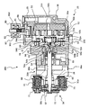
- the expander 23 of the pump-integrated expander 29A includes a fixed scroll 51 disposed at one end in the axial direction of the pump-integrated expander 29A and a orbiting scroll that is combined to be eccentrically engaged with the fixed scroll 51 ( (Rotary body) 52, a housing portion 54 having a discharge port 53, and a casing portion 56 having a suction port 55.
- the fixed scroll 51 includes a disk-shaped main body 51a, a scroll portion (spiral body) 51b standing in a rib shape on one end surface of the main body 51a, and a working fluid formed so as to penetrate the center of the main body 51a. And an inlet 51c.
- the housing part 54 is formed in a cylindrical shape with both ends open, a casing part 56 is fitted inside the housing part 54, a first hollow part 54 a in which the fixed scroll 51 and the orbiting scroll 52 are accommodated, the orbiting scroll 52 and the rotating shaft 28.
- a second hollow portion 54b that supports the large-diameter portion 64 that constitutes the driven crank mechanism, and a third hollow portion 54c that supports the rotary shaft 28.
- a discharge port 53 that communicates the inner space of the first hollow portion 54a (the discharge side space of the scroll) and the external space is formed along the radial direction of the rotary shaft 28 on the pump 25A side of the first hollow portion 54a. Has been.
- the casing portion 56 is integrally provided with the fixed scroll 51 on the inner side and the outer side is fitted with the cylindrical portion 56a fitted inside the first hollow portion 54a, and the working fluid introduction chamber communicated with the introduction port 51c of the fixed scroll 51. 56b, and a suction port 55 that communicates the working fluid introduction chamber 56b and the outer space of the casing portion 56 is formed along the radial direction of the rotary shaft 28.
- the discharge port 53 and the suction port 55 are provided substantially parallel to each other, extending in the same angular direction from the axis of the rotary shaft 28, and arranged side by side in the axial direction of the rotary shaft 28.
- One end of a pipe whose one end is connected to the outlet of the evaporator 22 is connected to the suction port 55, and the working fluid heated by the evaporator 22 is introduced into the expander 23 through the suction port 55. .
- the working fluid introduced into the suction port 55 flows into the working fluid introduction chamber 56b and is then introduced into the center portion of the fixed scroll 51 through the introduction port 51c.
- the working fluid introduced into the center of the fixed scroll 51 pushes the wall surface of the orbiting scroll 52 to form an expansion chamber, and the working fluid is continuously supplied to move the expansion chamber to the outer peripheral side. This causes a swivel motion.
- the orbiting scroll 52 includes a disk-shaped main body 52a and a scroll portion (spiral body) 52b that is provided in a rib shape on one end surface of the main body 52a.
- a rotation prevention mechanism 60 is provided between the surface opposite to the end surface of the main body portion 52a where the scroll portion 52b is formed and the step portion 54d from the first hollow portion 54a to the second hollow portion 54b of the housing portion 54.
- the orbiting scroll 52 performs the orbiting motion with the expansion of the working fluid while the rotation preventing mechanism 60 prevents the rotation.
- the rotation prevention mechanism 60 there are Oldham coupling, pin & ring coupling, ball coupling and the like.
- ball coupling using a ball as a rolling member is used, and in particular, EM coupling. (Refer to NTN TECHNIC REVIEW No. 68 (2000) “EM coupling for scroll compressor”).
- the EM coupling is composed of two plates and a steel ball (ball) obtained by integrally press-molding a race and a ring.
- a cylindrical portion 52c is formed to protrude from the end surface of the main body 52a of the orbiting scroll 52 on the side of the rotation prevention mechanism 60, and a drive bearing 61 is provided inside the cylindrical portion 52c.
- An eccentric bush 62 is fitted to the drive bearing 61, and a crank pin hole 62 a is formed in the eccentric bush 62.
- a large-diameter portion 64 is rotatably supported by the second hollow portion 54 b of the housing portion 54 via a bearing 63, and the large-diameter portion 64 is parallel to the rotary shaft 28 and with respect to the rotary shaft 28.
- the crank pin 64 a is erected by shifting the shaft center, and the crank pin 64 a is inserted into the crank pin hole 62 a of the eccentric bush 62.
- the rotary shaft 28 is connected to the large diameter portion 64, and the turning motion around the rotary shaft 28 of the orbiting scroll 52 is rotated by the driven crank mechanism including the eccentric bush 62, the crank pin 64 a, and the large diameter portion 64. Transmit as driving force. Further, a counterweight (balance weight) 74 for suppressing the occurrence of vibration of the expander 23 is attached to the eccentric bush 62.
- a restriction hole 64b is provided in the large diameter portion 64, and a restriction projection 62b that fits into the restriction hole 64b is provided in the eccentric bush 62. Oscillation of the eccentric bush 62 around the crank pin 64a is restricted by the engagement between the hole 64b and the restricting protrusion 62b.
- the rotary shaft 28 is supported by a bearing 65 provided in the third hollow portion 54 c of the housing portion 54 and is supported by a bearing 67 provided at an end portion of a pump housing 66 connected to the housing portion 54 to rotate.
- the pump housing 66 is provided with a pump 25A.
- the pump 25A is a gear pump as an example, and the gear pump is driven and supported by a drive gear (rotary body) supported on the rotary shaft 28, a driven shaft rotatably supported in parallel with the rotary shaft 28, and the driven shaft. And a driven gear meshing with the gear.
- the pump housing 66 is formed with a pump suction port 66a communicating with the suction port of the pump 25A and a pump discharge port 66b communicating with the discharge port of the pump 25A.
- One end of a pipe whose one end is connected to the outlet of the condenser 24 is connected to the pump suction port 66a, and the working fluid condensed (liquefied) by the condenser 24 is sucked into the pump 25A.
- the pump discharge port 66b is connected to the other end of a pipe whose one end is connected to the inlet of the evaporator 22, and the working fluid condensed (liquefied) by the condenser 24 is pumped to the evaporator 22 so that the working fluid is Is evaporated (vaporized).
- a well-known pump can be employ
- a pulley 31 and an electromagnetic clutch 34 that constitute the transmission mechanism 3 are arranged at the end of the rotary shaft 28 that extends through the pump housing 66 to the outside.
- a cylindrical portion 66c that encloses the rotary shaft 28 is integrally formed on the end surface of the pump housing 66 opposite to the expander 23 side.
- a bearing 67 that supports the rotary shaft 28 is disposed on the inner tip side of the tubular portion 66c, and a shaft seal 68 is disposed on the bottom side (expansion device 23 side) of the tubular portion 66c.
- the clutch board 71 is attached to the front-end
- a clutch coil 73 is accommodated in an annular groove 31a formed on the end face of the pulley 31 on the expander 23 side and centering on the rotary shaft 28.
- the electromagnetic clutch 34 includes the clutch plate 71 and the clutch coil 73 described above. Consists of. When the clutch coil 73 is energized, a magnetic attractive force is generated, so that the clutch plate 71 comes into contact with the pulley 31 and the pulley 31 and the clutch plate 71 (rotary shaft 28) are interlocked. Power is transmitted between the rotary shaft 28 of the body expander 29A and the engine 10 (crankshaft 10a).
- the expander 23 of the pump-integrated expander 29 ⁇ / b> A further includes a bypass for guiding the working fluid sucked from the suction port 55 to the discharge port 53, bypassing the drive unit including the fixed scroll 51 and the orbiting scroll 52.
- Part 80 is provided.
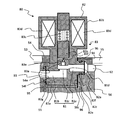
- the bypass part 80 includes a holder 82 in which a bypass path 81 is formed, and a valve mechanism (electromagnetic valve) 83 that is supported by the holder 82 and opens and closes the bypass path 81, and includes a suction port 55. 56 and a housing portion 54 having a discharge port 53.
- the valve mechanism 83 is an electromagnetic valve provided with a coil 83d. Further, shims 96 are sandwiched between the holder 82 and the casing portion 56 and between the housing portion 54 and the casing portion 56.
- the holder 82 includes a distal end portion 82 a where the bypass path 81 is formed and a proximal end portion 82 b that holds a coil of the valve mechanism 83.
- the distal end portion 82 a is in the axial direction of the rotary shaft 28 and the casing portion 56 and the housing. It is clamped between the parts 54.
- An accommodation space 91 is provided between the portion of the casing portion 56 where the suction port 55 is formed and the portion of the housing portion 54 where the discharge port 53 is formed.
- the housing space 91 is a space that is surrounded by the casing portion 56 and the housing portion 54 and that is open toward the outside in the radial direction of the rotating shaft 28.
- a suction side communication passage 92 communicating with the suction port 55 is opened on the surface of the casing portion 56 side that sandwiches the tip end portion 82 a of the holder 82 in the axial direction in the storage space 91, and the tip end portion 82 a is pivoted in the storage space 91.
- a discharge-side communication passage 93 communicating with the discharge port 53 is opened on the surface on the housing part 54 side sandwiched in the direction.
- a bypass path 81 extending in the axial direction of the rotary shaft 28 is formed at the distal end portion 82 a of the holder 82, and the distal end portion 82 a is sandwiched between the casing portion 56 and the housing portion 54 in the axial direction of the rotary shaft 28.
- bypass portion 80 (holder 82) is disposed between the suction port 55 and the discharge port 53, and directly communicates the suction port 55 and the discharge port 53 with the bypass passage 81 formed in the holder 82.
- the portion of the holder 82 where the end portion on the casing portion 56 side of the bypass path 81 opens forms a cylindrical protrusion 82 c that is formed in a cylindrical shape along a direction parallel to the axis of the rotary shaft 28.
- a bypass path 81 extends in the axial center portion of the protrusion 82c.
- the suction side communication passage 92 has a fitting hole (a diameter-enlarged portion) 92a having a diameter into which the cylindrical projection 82c is fitted and inserted on the holder 82 side (housing portion 54 side). That is, the suction side communication path 92 is formed with a diameter substantially equal to that of the bypass path 81 from the suction port 55 side, and is expanded to a diameter in which the outer periphery of the cylindrical protrusion 82c is fitted.
- An annular groove 82f is formed on the outer periphery of the cylindrical protrusion 82c, and a seal member (O-ring) 94 formed in an annular shape by an elastic material such as rubber is fitted into the annular groove 82f.
- a seal member (O-ring) 94 formed in an annular shape by an elastic material such as rubber is fitted into the annular groove 82f.
- the bypass path 81 communicates with the suction port 55 and the position of the holder 82 in the radial direction of the rotary shaft 28 is set.
- the cylindrical port portion 82 c of the holder 82 and the fitting hole portion 92 a of the casing portion 56 in other words, the suction port 55 side of the bypass path 81 is sealed by a cylindrical seal. Sealed.
- the holder 82 and the casing portion 56 abut each other in the axial direction of the rotary shaft 28 between the flat portion 82e at the base portion of the cylindrical protrusion 82c and the flat portion 56c where the suction side communication passage 92 of the casing portion 56 opens.
- the shim 96 which is metal clamping plates, for example is pinched
- the clearance between the fixed scroll 51 and the orbiting scroll 52 in the axial direction 28 is adjusted.
- the bypass path 81 on the holder 82 side and the discharge side on the housing portion 54 side The communication path 93 is continuous, and the bypass path 81 is connected to the discharge port 53 via the discharge side communication path 93.
- the bypass path 81 is formed from the tip of the cylindrical protrusion 82 c to the pedestal portion 82 g (planar portion), and the holder 82 is sandwiched between the housing portion 54 and the casing portion 56, whereby the suction port 55.
- the discharge port 53 communicate with each other by a bypass path 81.
- An annular groove 54f is formed on the bottom surface of the recessed portion 54e so as to surround the opening of the discharge side communication passage 93, and a seal member 95 made of an elastic material such as rubber is fitted into the groove 54f.
- the sealing member 95 is sealed so as to surround the contact surface between the holder 82 and the housing portion 54. That is, the periphery of the connection portion between the bypass path 81 on the holder 82 side and the discharge side communication passage 93 on the housing portion 54 side is sealed with a flat seal. In other words, the bypass passage 81 and the discharge port 53 are sealed with a flat seal.
- the seal member 95 is crushed by the holder 82 to generate a force that urges the holder 82 toward the casing portion 56, whereby the holder 82 abuts against the casing portion 56 and the holder 82 rotates.
- the position of the shaft 28 in the axial direction is positioned with reference to the casing portion 56.
- the holder 82 of the bypass unit 80 is integrally provided with a valve mechanism (pilot electromagnetic valve) 83 that opens and closes the bypass path 81.
- the bypass path 81 includes a pipe line 81a that extends in parallel to the axial direction of the rotary shaft 28 from the casing part 56 side, and a pipe line 81b that extends in parallel to the axial direction of the rotary shaft 28 from the housing part 54 side. Is formed at a position farther from the rotary shaft 28 than the pipe 81b, and the pipes 81a and 81b communicate with each other through a pipe 81c extending in the radial direction of the rotary shaft 28.
- the pipe line 81c there is a seat part 81d for closing the pipe line 81c (bypass path 81) in the seated state, with the valve body 83a moving and seating from the outside in the radial direction of the rotary shaft 28 to the inside.
- the plunger 83b is supported so as to be displaceable along the radial direction outside the seat portion 81d in the radial direction.
- the plunger 83b is urged toward the seat portion 81d by the coil spring (elastic body) 83c (in a direction approaching the rotation shaft 28) and resists the urging force of the coil spring 83c by the magnetic force of the coil (solenoid) 83d. Thus, it is displaced in a direction away from the sheet portion 81d (rotating shaft 28).
- the base end portion 82b of the holder 82 that accommodates the coil 83d is exposed to the outside of the casing portion 56 and the housing portion 54, and a terminal (not shown) for energizing the coil 83d is exposed to the outside. (Omitted) is provided.
- a valve body 83a is supported between the plunger 83b and the seat portion 81d so as to be displaceable in the same direction as the advance / retreat direction of the plunger 83b (the radial direction of the rotary shaft 28).
- the valve body 83a is formed with a pilot path 83e penetrating in the displacement direction of the valve body 83a, and a pilot valve 83f for closing the opening of the pilot path 83e on the plunger 83b side is formed at the tip of the plunger 83b. ing.
- the plunger 83b In the non-energized state of the coil 83d, the plunger 83b is displaced toward the seat portion 81d by the biasing force of the coil spring 83c, so that the valve body 83a is seated on the seat portion 81d by being pushed by the plunger 83b, and The opening on the plunger 83b side of the pilot path 83e is closed by the pilot valve 83f, so that the flow of the working fluid through the bypass path 81 is blocked.
- the plunger 83b When the coil 83d is energized from the closed state, the plunger 83b is separated from the valve body 83a seated on the seat portion 81d by the magnetic force of the coil 83d, so that the pilot valve 83f is opened from the opening on the plunger 83b side of the pilot path 83e. The pilot path 83e is released and the pilot path 83e is opened.
- the plunger 83b When the energization to the coil 83d is interrupted from the valve open state (energized state), the plunger 83b is displaced in the direction approaching the seat portion 81d by the biasing force of the coil spring 83c, the pilot path 83e is closed, and the plunger 83b is further closed.
- the valve body 83a is displaced in a direction approaching the seat portion 81d by being pushed, the valve body 83a is seated on the seat portion 81d and returns to the valve closed state, and the valve 83 is closed while the coil 83d is continuously de-energized. Hold.
- the valve mechanism 83 that opens and closes the bypass passage 81 is a so-called pilot-type electromagnetic valve that includes the valve body 83a, the plunger 83b, the coil spring 83c, the coil 83d, and the like.
- the valve mechanism 83 is not limited to a pilot-type electromagnetic valve that drives a valve body using a pressure difference between fluids, and is a direct-acting electromagnetic valve that mechanically opens and closes the valve body by driving a movable core. can do.
- the control unit 4 opens the valve mechanism 83 by energizing the coil 83d immediately after the start of the Rankine cycle device 2A with the electromagnetic clutch 34 engaged, and connects the suction port 55 and the discharge port 53 to the bypass path 81.
- the working fluid circulated by the pump 25 ⁇ / b> A driven by the engine 10 flows around the scrolls 51 and 52 as the drive unit.
- the expander 23 is integrally provided with the bypass path 81 and the valve mechanism 83 that opens and closes the bypass path 81, the bypass path including the valve mechanism is provided in the piping for circulating the working fluid. Compared to the case of connection, the working fluid circulation circuit in the Rankine cycle device 2A can be simplified.
- a holder 82 (bypass portion 80) having a bypass passage 81 and integrally including a valve mechanism 83 is connected to a casing portion 56 in which a suction port 55 is formed, and a housing portion 54 in which a discharge port 53 is formed. Therefore, the bypass path 81 and the valve mechanism 83 can be provided with a simple structure with respect to the expander 23 (fluid machine), the processing of the expander 23 is simplified, and the shaft of the expander 23 is provided. Expansion of the direction length can be suppressed. Further, in the valve mechanism 83, the movement direction of the plunger 83b and the valve body 83a is set in the radial direction of the rotary shaft 28.
- the movement space of the plunger 83b and the valve body 83a is long in the radial direction of the rotary shaft 28 and moves. Compared with the case where the direction is a direction parallel to the rotation shaft 28, the axial length of the expander 23 can be suppressed.
- the coil (solenoid) 83d of the valve mechanism 83 is accommodated in the base end portion 82b of the holder 82 exposed to the outside of the casing portion 56 and the housing portion 54, heat can be efficiently radiated from the coil 83d. it can.
- the coil (solenoid) 83d which is a large component among the components constituting the valve mechanism 83, is arranged outside the portion sandwiched between the casing portion 56 and the housing portion 54, the coil (solenoid) 83d There is no need to secure the accommodation space in a portion sandwiched between the casing portion 56 and the housing portion 54, and the axial length of the expander 23 can also be suppressed by this.
- one connection portion of the bypass path 81 is a cylindrical seal, and the other connection portion is a planar seal.
- the holder 82 (bypass portion 80) can be easily positioned while blocking the leakage path of the working fluid. Further, since the bypass path 81 directly connects the suction port 55 and the discharge port 53, the bypass path has no sliding portion such as the rotation prevention mechanism 60 of the orbiting scroll 52, and the bypass path 81 is opened.
- FIG. 4 shows a pump-integrated expander 29A including the expander 23 in which the annular space (discharge side) surrounding the orbiting scroll 52 and the suction port 55 are connected by a bypass.
- the discharge port 53 formed in the housing portion 54 opens in a direction different from the suction port 55 in the radial direction of the rotation shaft 28 (as an example, a substantially opposite direction).
- the housing portion 54 facing the portion where the suction side communication path 92 of the casing portion 56 is formed has a recessed portion 54 e and A discharge side communication passage 93 is formed.
- the discharge side communication passage 93 is connected to the bypass space 102 communicating with the annular space (discharge side space) 101 surrounding the orbiting scroll 52, while the discharge port 53 is connected to the outside of the housing portion 54 and the annular space 101.
- the suction port 55 communicates with the annular space (discharge side space) 101 via the suction side communication path 92, the bypass path 81, the discharge side communication path 93, and the bypass space 102, and the working fluid is used as a drive unit.
- the working fluid that can circulate around the scroll and bypass the scrolls 51, 52 from the suction port 55 and flows into the annular space (discharge side space) 101 is discharged from the annular space 101 through the discharge port 53 to the outside. Will be.
- the expander 23 in FIG. 4 is different from the expander 23 shown in FIG. 2 in the arrangement of the discharge port 53, so that the target to be connected to the bypass path 81 via the discharge side communication path 93 Since the port 53 is changed to the annular space (discharge side space) 101, the structures of the scrolls 51 and 52, the pump 25A, the transmission mechanism 3, the bypass unit 80, and the like are the same as those of the expander 23 in FIG. Detailed description is omitted. Also in the expander 23 of FIG. 4, by holding the holder 82 (bypass unit 80) between the casing portion 56 and the housing portion 54, the same operation and effect as the expander 23 shown in FIG. 2 can be obtained. Can do.
- the discharge port 53 and the suction port 55 can be opened in different radial directions of the rotary shaft 28, the direction of the discharge port 53 and the suction port 55 can be set as compared with the expander 23 of FIG. There are few restrictions and high versatility.
- the working fluid bypasses the scrolls 51 and 52 from the suction port 55 and flows into the annular space (discharge side space) 101, and the sliding of the orbiting scroll 52 such as the rotation prevention mechanism 60 is performed. Since it flows to the discharge port 53 after passing through the annular space (discharge side space) 101 where the portion exists, it has a sliding portion in the middle of the bypass path. For this reason, compared with the expander 23 shown in FIG.
- the expander 23 in FIG. 4 is disadvantageous in securing the lubricity of the sliding part.
- a ball coupling type rotation prevention mechanism such as an EM coupling
- seizure does not occur even in a state of insufficient lubrication and has high durability. Therefore, even if the working fluid that circulates around the scrolls 51 and 52 is gas-liquid mixed or liquid phase, sufficient durability can be maintained.
- the expander 23 shown in FIG. 2 or FIG. 4 includes the pump 25A integrally, but instead of the pump 25A or together with the pump 25A, the generator can be integrated with the expander 23.
- the bypass structure using the holder 82 (bypass unit 80) can also be applied to an expander that does not include the pump 25A or the generator.
- the expander 23 may be a rotary expander provided with a rotary piston as a drive unit in addition to the scroll type.
- the cylindrical projection 82c of the holder 82 is provided on the surface facing the housing portion 54, the cylindrical projection 82c is fitted into the discharge side communication passage 93, and the pedestal portion 82g of the holder 82 is connected to the casing portion.
- the base portion 82g can be abutted against the surface of the casing portion 56 where the suction side communication passage 92 is opened.
- the connecting portion on the housing portion 54 side of the bypass passage 81 can be sealed with a cylindrical seal
- the connecting portion on the casing portion 56 side of the bypass passage 81 can be sealed with a flat seal.
- fluid machine is not limited to the expander 23, and may be a compressor.
- fluid machines, such as the expander 23, are not limited to what is integrated in a waste-heat utilization apparatus (Rankine cycle apparatus).
- Valve mechanism 83a Valve body 83b ... Plunger 83c ... Coil spring 83d ... Coil 83d, 92 ... suction side communication passage, 92a ... fitting hole (diameter enlarged portion), 93 ... discharge side communication passage
Landscapes
- Engineering & Computer Science (AREA)
- Chemical & Material Sciences (AREA)
- Combustion & Propulsion (AREA)
- Mechanical Engineering (AREA)
- General Engineering & Computer Science (AREA)
- Physics & Mathematics (AREA)
- Fluid Mechanics (AREA)
- Applications Or Details Of Rotary Compressors (AREA)
- Compressor (AREA)
- Rotary Pumps (AREA)
Description
例えば、特許文献1の流体機械は、弁機構が、弁体の背圧を電磁弁で制御することで、バイパス通路を開閉する構成であるため、電磁弁の収容空間、背圧室、該背圧室(高圧室)と低圧室とを連通させる通路などを、ケーシングやハウジングに形成する必要が生じ、加工が複雑になってしまう。
更に、特許文献1の流体機械では、固定スクロールの背面側に、作動流体が流入する高圧室が設けられ、更に、この高圧室の外側に電磁弁や背圧室などを配設するため、流体機械の軸方向の長さが増大してしまう。
図1は、流体機械としての膨張機が組み込まれる車両用の廃熱利用装置1Aを示す。
廃熱利用装置1Aは、エンジン10と共に車両に搭載され、エンジン10の廃熱を回収して利用する装置である。
エンジン10は、水冷式の冷却装置を備えた内燃機関であり、前記冷却装置は、冷却水を循環させる冷却水循環路11を備える。
冷却水循環路11には、ランキンサイクル装置2Aの蒸発器22を配置してあり、エンジン10から熱を吸収した冷却水を、蒸発器22を通過させてから再度エンジン10に戻す。
ランキンサイクル装置2Aは、作動流体を循環させる循環路21を備え、この循環路21に、作動流体の流れ方向に沿って、蒸発器22、膨張機23、凝縮器24及びポンプ25Aをこの順に配置してある。
前記作動流体(冷媒)としては、例えばフルオロカーボンからなる骨格を基本とするものが用いられ、また、潤滑油が作動流体と共に循環し、膨張機23やポンプ25Aの摺動部における潤滑、密封、冷却等の役割を担う。
膨張機23(流体機械)は、蒸発器22で気化し高温,高圧となった作動流体を膨張させることで、駆動力を発生する装置であり、一例としてスクロール型膨張機を用いる。
ポンプ25Aは機械式ポンプであり、凝縮器24で液化した作動流体を蒸発器22へと圧送する。
このように、作動流体は、気化、膨張、凝縮を繰り返しながら循環路21を循環する。
そして、ランキンサイクル装置2Aは、まずエンジン10の出力によってポンプ25Aを駆動することによって起動し、その後、膨張機23が十分な駆動力を発生するようになると、膨張機23の駆動力がポンプ25Aを駆動するようになる。
伝達機構3は、ポンプ一体型膨張機29Aの回転軸28に取り付けたプーリ31と、エンジン10のクランクシャフト10aに取り付けたクランクプーリ32と、プーリ31及びクランクプーリ32に巻回したベルト33と、ポンプ一体型膨張機29Aの回転軸28とプーリ31との間に設けた電磁クラッチ34と、を備える。
マイクロコンピュータを備える制御ユニット4は、電磁クラッチ34を制御する機能を有し、電磁クラッチ34をオン/オフ制御することで、ランキンサイクル装置2Aの作動/停止を制御する。
そして、膨張機23が作動して駆動力を発生するようになると、膨張機23で発生した駆動力の一部がポンプ25Aを駆動し、その余の駆動力を、伝達機構3を介してエンジン10に伝達し、エンジン10の出力(駆動力)をアシストする。
尚、蒸発器22を、ランキンサイクル装置2Aの作動流体と、エンジン10の排気との間で熱交換を行う装置とすることができ、また、エンジン10の冷却水との間で熱交換を行うと共に、エンジン10の排気との間で熱交換を行う装置とすることができる。
そして、制御ユニット4は、電磁クラッチ34を締結させたランキンサイクル装置2Aの起動直後において、弁機構83を開に制御してバイパス路81を開き、膨張機23のスクロールを迂回させて作動流体を循環させるようにする。
このように、ランキンサイクル装置2Aの起動直後に、膨張機23のスクロールを迂回して作動流体を循環させるようにすれば、蒸発器22内の圧力が低下して作動流体の蒸発温度が低くなるため、ランキンサイクル装置2Aの起動性を向上させることができる。また、ランキンサイクル装置2Aの停止時、電磁クラッチ34を解放(オフ)した時に、残圧力によって高回転になってしまうのを防ぐために、バイパス路81を開にする。
ポンプ一体型膨張機29Aは、前述のように、ランキンサイクル装置2Aの作動流体を循環させるポンプ25Aと、蒸発器22で加熱されて気化した作動流体の膨張によって回転駆動力を発生する膨張機23とが共通の回転軸28によって駆動される流体機械であり、伝達機構3を構成するプーリ31及び電磁クラッチ34を備えている。
固定スクロール51は、円盤状の本体部51aと、本体部51aの一端面にリブ状に立設したスクロール部(渦巻き体)51bと、本体部51aの中央を貫通するように形成した作動流体の導入口51cとを有する。
そして、第1中空部54aのポンプ25A側に、第1中空部54aの内空間(スクロールの吐出側空間)と外部空間とを連通させる吐出ポート53が、回転軸28の径方向に沿って形成されている。
ここで、吐出ポート53及び吸入ポート55は、相互に略平行に、かつ、回転軸28の軸心から同一の角度方向に向けて延設され、回転軸28の軸方向に並んで設けられる。
吸入ポート55に導入された作動流体は、作動流体導入室56bに流入した後、導入口51cを介して固定スクロール51の中心部に導入される。
固定スクロール51の中心部に導入された作動流体は、旋回スクロール52の壁面を押して膨張室を形成し、作動流体が連続して供給されることで膨張室を外周側に移動させ、旋回スクロール52の旋回運動を生じさせる。
旋回スクロール52は、円盤状の本体部52aと、本体部52aの一端面にリブ状に立設したスクロール部(渦巻き体)52bとを有する。
尚、自転阻止機構60としては、オルダムカップリング、ピン&リングカップリング、ボールカップリングなどがあるが、ここでは、ボールを転動部材としたボールカップリングを用いており、特に、EMカップリングと呼ばれるボールカップリングを用いている(NTN TECHNICAL REVIEW No.68(2000)「スクロールコンプレッサ用EMカップリングについて」参照)。EMカップリングは、レースとリングを一体プレス成形した2枚のプレートと鋼球(ボール)とから構成される。
一方、ハウジング部54の第2中空部54bには、ベアリング63を介して大径部64が回転可能に支持され、この大径部64には、回転軸28と平行にかつ回転軸28に対して軸心をずらしてクランクピン64aを立設してあり、クランクピン64aは、前記偏心ブッシュ62のクランクピン孔62aに挿通される。
また、膨張機23の振動発生を抑制するためのカウンタウェイト(バランスウェイト)74を、偏心ブッシュ62に対して取り付けてある。
回転軸28は、ハウジング部54の第3中空部54cに設けたベアリング65に支持されると共に、ハウジング部54に連結されるポンプハウジング66の端部に設けたベアリング67に支持されて回転する。
ポンプハウジング66には、ポンプ25Aの吸入口に連通するポンプ吸入ポート66a、及び、ポンプ25Aの吐出口に連通するポンプ吐出ポート66bが形成される。
尚、ポンプ25Aとして、公知のポンプを適宜採用でき、ギヤポンプの他、ベーンポンプなどを用いることができる。
ポンプハウジング66を貫通して外部に延設した回転軸28の端部には、伝達機構3を構成するプーリ31と電磁クラッチ34とを配置してある。
そして、筒状部66cから突き出た回転軸28の先端にクラッチ板71を取り付け、また、筒状部66cの外周に、ベアリング72を介してプーリ31を回転可能に取り付けてある。
そして、クラッチコイル73に通電すると、磁気吸引力が発生することでクラッチ板71がプーリ31に接触し、プーリ31とクラッチ板71(回転軸28)とが連動するようになり、結果、ポンプ一体型膨張機29Aの回転軸28とエンジン10(クランクシャフト10a)との間で動力の伝達が行われるようになる。
バイパス部80は、バイパス路81が形成されるホルダ82と、該ホルダ82に支持されてバイパス路81を開閉する弁機構(電磁弁)83と、を有し、吸入ポート55を備えたケーシング部56と、吐出ポート53を備えたハウジング部54との間に挟持される。
なお、弁機構83は、コイル83dを備えた電磁弁である。また、ホルダ82とケーシング部56との間、及び、ハウジング部54とケーシング部56との間には、シム96を挟着してある。
ホルダ82は、バイパス路81が形成される先端部82aと、弁機構83のコイルなどを保持する基端部82bとからなり、先端部82aが、回転軸28の軸方向においてケーシング部56とハウジング部54との間に挟持される。
ケーシング部56の吸入ポート55が形成される部分と、ハウジング部54の吐出ポート53が形成される部分との間に、ホルダ82の先端部82aを挟持するための収容空間91を設けてある。前記収容空間91は、ケーシング部56及びハウジング部54で囲まれる、有底で、かつ、回転軸28の径方向の外方に向けて開放される空間である。
そして、ホルダ82の先端部82aには、回転軸28の軸方向に延びるバイパス路81が形成され、先端部82aが、回転軸28の軸方向においてケーシング部56とハウジング部54との間に挟持された状態で、バイパス路81の一端が吸入側連通路92に接続され、バイパス路81の他端が吐出側連通路93に接続されることで、作動流体のバイパス管路が形成される。
このように、バイパス部80(ホルダ82)は、吸入ポート55と吐出ポート53との間に配設され、ホルダ82に形成したバイパス路81で吸入ポート55と吐出ポート53とを直接的に連通させる。
一方、吸入側連通路92は、ホルダ82側(ハウジング部54側)に、前記円筒状突起部82cが嵌挿される径の嵌合孔部(拡径部)92aを有する。即ち、吸入側連通路92は、吸入ポート55側からバイパス路81と略同等の径で形成され、途中で、円筒状突起部82cの外周が嵌挿される径に拡径される。
即ち、円筒状突起部82cを吸入側連通路92の嵌合孔部92aに嵌合させることで、バイパス路81が吸入ポート55に連通すると共に、回転軸28の径方向におけるホルダ82の位置が吸入側連通路92を基準に位置決めされ、ホルダ82の円筒状突起部82cとケーシング部56の嵌合孔部92aとの間、換言すれば、バイパス路81の吸入ポート55側は、円筒シールによってシールされる。
また、バイパス路81のハウジング部54側の端部が開口するホルダ82の部分には、回転軸28の横断面に平行な突き当り面を形成する台座部82gを突出形成してある一方、ハウジング部54には、前記台座部82gが遊嵌されると共に、前記台座部82gの端面(平面部)と平行でかつ吐出側連通路93が開口する底面(平面部)を備えた凹陥部54eを形成してある。
即ち、バイパス路81は、円筒状突起部82cの先端から台座部82g(平面部)にかけて形成されており、ホルダ82をハウジング部54とケーシング部56との間に挟持することで、吸入ポート55と吐出ポート53とが、バイパス路81によって連通する。
凹陥部54eの底面には、吐出側連通路93の開口を囲むように、環状に溝54fを形成してあり、この溝54fに、ゴムなどの弾性材料で形成したシール部材95を嵌め込み、このシール部材95によって、ホルダ82とハウジング部54との突き当り面を囲むようにしてシールする。即ち、ホルダ82側のバイパス路81とハウジング部54側の吐出側連通路93との接続部は、その周囲が平面シールでシールされる。換言すれば、バイパス路81と吐出ポート53は、平面シールでシールされる。
また、バイパス部80のホルダ82は、バイパス路81を開閉する弁機構(パイロット式電磁弁)83を一体的に備えている。
管路81cには、回転軸28の径方向の外側から内側に向けて弁体83aが移動して着座し、係る着座状態で管路81c(バイパス路81)を閉塞するためのシート部81dが形成されており、また、シート部81dよりも前記径方向の外側において前記径方向に沿って変位可能に、プランジャ83bを支持してある。
ここで、コイル83dを収容するホルダ82の基端部82bは、ケーシング部56及びハウジング部54の外部に露出し、この外部に露出する部分に、コイル83dへの通電を行うための端子(図示省略)が設けられる。
弁体83aには、弁体83aの変位方向に貫通するパイロット路83eが形成されており、プランジャ83bの先端には、前記パイロット路83eのプランジャ83b側の開口を閉塞するパイロット弁83fが形成されている。
係る閉塞状態からコイル83dに通電すると、コイル83dの磁気力によってプランジャ83bが、シート部81dに着座している弁体83aから離れることで、パイロット弁83fがパイロット路83eのプランジャ83b側の開口から離れ、パイロット路83eが開放される。
係る開弁状態(通電状態)から、コイル83dへの通電を遮断すると、プランジャ83bがコイルバネ83cの与勢力によってシート部81dに近づく方向に変位してパイロット路83eが閉塞され、更に、プランジャ83bに押されて弁体83aがシート部81dに近づく方向に変位し、弁体83aがシート部81dに着座して閉弁状態に戻り、コイル83dへの非通電が継続されている間、閉弁状態を保持する。
尚、弁機構83は、流体の圧力差を用いて弁体を駆動させるパイロット式の電磁弁に限定されず、可動コアの駆動によって機械的に弁体を開閉動作させる直動式の電磁弁とすることができる。
上記のように、膨張機23は、バイパス路81と当該バイパス路81を開閉する弁機構83とを一体的に備えるから、作動流体を循環させるための配管に、弁機構を備えたバイパス路を接続する場合に比べて、ランキンサイクル装置2Aにおける作動流体の循環回路を簡略化できる。
また、弁機構83は、プランジャ83b及び弁体83aの移動方向が、回転軸28の径方向に設定されるから、プランジャ83b及び弁体83aの移動空間は回転軸28の径方向に長く、移動方向を回転軸28と平行な方向とする場合に比べて、膨張機23の軸方向長さを抑制できる。
また、弁機構83を構成する部品の中でサイズが大きな部品であるコイル(ソレノイド)83dを、ケーシング部56とハウジング部54とで挟まれる部分の外側に配置するから、コイル(ソレノイド)83dの収容空間を、ケーシング部56とハウジング部54とで挟まれる部分に確保する必要がなく、これによっても、膨張機23の軸方向長さを抑制できる。
更に、バイパス路81は、吸入ポート55と吐出ポート53とを直接的に接続するから、バイパス経路に、旋回スクロール52の自転阻止機構60などの摺動部がなく、バイパス路81を開放しているときに気液混合状態又は液相状態の作動流体が流れても、係る作動流体によって摺動部の潤滑油の粘性が低下して、摺動部の潤滑性が低下することを抑制できる。
図4は、旋回スクロール52を囲む環状空間(吐出側)と吸入ポート55とを、バイパス路で接続するようにした膨張機23を含む、ポンプ一体型膨張機29Aを示す。
また、図4に示す膨張機23では、図2に示した膨張機23と同様に、ケーシング部56の吸入側連通路92が形成される部分に対向するハウジング部54には、凹陥部54e及び吐出側連通路93を形成してある。
即ち、吸入側連通路92、バイパス路81、吐出側連通路93、バイパス空間102を介して、吸入ポート55と環状空間(吐出側空間)101とが連通し、作動流体を、駆動部としてのスクロールを迂回して循環させることができ、吸入ポート55からスクロール51,52を迂回して環状空間(吐出側空間)101に流入した作動流体は、環状空間101から吐出ポート53を経て外部に吐出されることになる。
図4の膨張機23においても、ケーシング部56とハウジング部54との間にホルダ82(バイパス部80)を挟持することで、図2に示した膨張機23と同様な作用、効果を得ることができる。
尚、図4の膨張機23では、作動流体が、吸入ポート55からスクロール51,52を迂回して環状空間(吐出側空間)101に流入し、旋回スクロール52の自転阻止機構60などの摺動部が存在する環状空間(吐出側空間)101を通過してから吐出ポート53にまで流れるため、バイパス経路の途中に摺動部を有することになる。
このため、バイパス経路に摺動部が存在しない図2に示した膨張機23に比べて、図4の膨張機23は、摺動部の潤滑性を確保する点では不利になる。しかし、自転阻止機構60としてEMカップリングなどのボールカップリング式の自転阻止機構を用いる場合、潤滑不足の状態においても焼付き等の不具合が発生せず、高い耐久性を有することが実験によって確認されているから、スクロール51,52を迂回して循環させる作動流体が気液混合又は液相であっても、十分な耐久性を維持できる。
例えば、図2又は図4に示した膨張機23は、ポンプ25Aを一体的に備えるが、ポンプ25Aに代えて又はポンプ25A共に発電機を膨張機23と一体的に備えることができ、また、ポンプ25Aや発電機を備えない膨張機にも、上記のホルダ82(バイパス部80)によるバイパス構造を適用できる。
また、ホルダ82の円筒状突起部82cを、ハウジング部54に対向する面に設けて、当該円筒状突起部82cを吐出側連通路93に嵌合させ、ホルダ82の台座部82gを、ケーシング部56に対向する面に設け、当該台座部82gを吸入側連通路92が開口するケーシング部56の面に突き当てるようにすることができる。換言すれば、バイパス路81のハウジング部54側の接続部を、円筒シールでシールし、バイパス路81のケーシング部56側の接続部を、平面シールでシールすることができる。
更に、膨張機23などの流体機械は、廃熱利用装置(ランキンサイクル装置)に組み込まれるものに限定されるものではない。
Claims (8)
- 高圧の加熱蒸気となった作動流体が流入する吸入ポートと、
前記吸入ポートを備えたケーシング部と、
前記吸入ポートから吸入した作動流体の膨張によって駆動される駆動部と、
前記駆動部を通過して低圧となった作動流体が流出する吐出ポートと、
前記吐出ポートを備えたハウジング部と、
を有する流体機械であって、
前記吸入ポートから吸入される作動流体を前記駆動部を迂回して前記吐出ポートに導くバイパス路が形成されると共に前記バイパス路を開閉する弁機構を備えたバイパス部を、前記ケーシング部と前記ハウジング部との間に挟持した、流体機械。 - 前記弁機構が、弁体をコイルの磁力によって前記駆動部の回転軸の径方向に変位させて前記バイパス路を開閉する電磁弁である、請求項1記載の流体機械。
- 前記バイパス部の前記コイルの収容部が、前記ケーシング部及び前記ハウジング部の外部に露出する、請求項2記載の流体機械。
- 前記バイパス路の一方端を円筒シールで、他方端を平面シールでシールする、請求項1記載の流体機械。
- 前記吸入ポート及び前記吐出ポートが、前記駆動部の回転軸の径方向に延び、かつ、前記回転軸の軸方向に並んで設けられ、
前記バイパス部を、前記吸入ポートと前記吐出ポートとの間に配設して、前記吸入ポートと前記吐出ポートとを前記バイパス路を介して連通させる、請求項1記載の流体機械。 - 前記バイパス路の一方端を前記吸入ポートに接続し、前記バイパス路の他端を、前記駆動部の吐出側であって前記吐出ポートに連通する空間に接続した、請求項1記載の流体機械。
- 前記流体機械が、固定スクロールと可動スクロールとからなる前記駆動部を備えたスクロール型膨張機であって、かつ、車両用エンジンの廃熱を回収して利用するランキンサイクル装置に組み込まれる、請求項1記載の流体機械。
- 前記流体機械は自転阻止機構を備えたスクロール型膨張機であって、
前記自転阻止機構は、ボールを転動部材としたボールカップリング式の自転阻止機構である、請求項1記載の流体機械。
Priority Applications (3)
| Application Number | Priority Date | Filing Date | Title |
|---|---|---|---|
| CN201380014059.XA CN104169527A (zh) | 2012-03-14 | 2013-03-13 | 流体设备 |
| DE112013001450.5T DE112013001450T5 (de) | 2012-03-14 | 2013-03-13 | Fluidmaschine |
| US14/385,454 US20150033744A1 (en) | 2012-03-14 | 2013-03-13 | Fluid Machine |
Applications Claiming Priority (2)
| Application Number | Priority Date | Filing Date | Title |
|---|---|---|---|
| JP2012057347A JP5969227B2 (ja) | 2012-03-14 | 2012-03-14 | 流体機械 |
| JP2012-057347 | 2012-03-14 |
Publications (1)
| Publication Number | Publication Date |
|---|---|
| WO2013137352A1 true WO2013137352A1 (ja) | 2013-09-19 |
Family
ID=49161257
Family Applications (1)
| Application Number | Title | Priority Date | Filing Date |
|---|---|---|---|
| PCT/JP2013/057084 Ceased WO2013137352A1 (ja) | 2012-03-14 | 2013-03-13 | 流体機械 |
Country Status (5)
| Country | Link |
|---|---|
| US (1) | US20150033744A1 (ja) |
| JP (1) | JP5969227B2 (ja) |
| CN (1) | CN104169527A (ja) |
| DE (1) | DE112013001450T5 (ja) |
| WO (1) | WO2013137352A1 (ja) |
Families Citing this family (7)
| Publication number | Priority date | Publication date | Assignee | Title |
|---|---|---|---|---|
| JP5804879B2 (ja) * | 2011-09-30 | 2015-11-04 | 日産自動車株式会社 | 廃熱利用装置 |
| CN104603439B (zh) * | 2012-07-09 | 2016-08-17 | 三电控股株式会社 | 发动机的废热利用装置 |
| DE102013226742A1 (de) * | 2013-12-19 | 2015-06-25 | Mahle International Gmbh | Strömungsmaschine |
| JP6228027B2 (ja) * | 2014-02-12 | 2017-11-08 | サンデンホールディングス株式会社 | スクロール膨張機 |
| DE102015213387A1 (de) * | 2015-07-16 | 2017-01-19 | Robert Bosch Gmbh | Rotationskolbenpumpe |
| US20190048749A1 (en) * | 2016-03-24 | 2019-02-14 | Robert Bosch Gmbh | Waste heat recovery system |
| DE102017201056A1 (de) * | 2017-01-24 | 2018-07-26 | Robert Bosch Gmbh | Gasventil für einen Wärmekreislauf eines Fahrzeugs und Herstellungsverfahren für ein Gasventil |
Citations (2)
| Publication number | Priority date | Publication date | Assignee | Title |
|---|---|---|---|---|
| JP2007231855A (ja) * | 2006-03-01 | 2007-09-13 | Denso Corp | 膨張機およびその制御装置 |
| JP2010236360A (ja) * | 2009-03-30 | 2010-10-21 | Sanden Corp | 流体機械、当該流体機械を用いた冷媒回路及び廃熱利用装置 |
Family Cites Families (12)
| Publication number | Priority date | Publication date | Assignee | Title |
|---|---|---|---|---|
| JPS6141882U (ja) * | 1984-08-22 | 1986-03-17 | 三菱重工業株式会社 | スクロ−ル型流体機械 |
| CN2143678Y (zh) * | 1992-12-19 | 1993-10-13 | 西安交通大学 | 带有防自转机构的涡旋式流体机械 |
| EP1443201B1 (en) * | 2003-01-28 | 2016-03-23 | Denso Corporation | Fluid machine operable in both pump mode and motor mode and waste heat recovering system having the same |
| JP2005030312A (ja) * | 2003-07-14 | 2005-02-03 | Toyota Industries Corp | 膨張機兼圧縮機 |
| JP4034291B2 (ja) * | 2004-04-26 | 2008-01-16 | 株式会社デンソー | 流体機械 |
| DE102005051428B4 (de) * | 2004-10-29 | 2015-05-28 | Denso Corporation | Abwärmenutzungsvorrichtung |
| US7870733B2 (en) * | 2005-12-21 | 2011-01-18 | Denso Corporation | Fluid machine for rankine cycle |
| JP4684882B2 (ja) * | 2005-12-21 | 2011-05-18 | 株式会社デンソー | 流体機械 |
| JP4864689B2 (ja) * | 2006-04-17 | 2012-02-01 | 株式会社デンソー | 流体機械およびランキンサイクル |
| JP5084342B2 (ja) * | 2007-04-27 | 2012-11-28 | サンデン株式会社 | 流体機械、該流体機械を用いたランキン回路及び車両の廃熱利用システム |
| JP4903826B2 (ja) * | 2009-02-25 | 2012-03-28 | 日立アプライアンス株式会社 | スクロール流体機械 |
| JP5278496B2 (ja) * | 2011-03-25 | 2013-09-04 | 株式会社豊田自動織機 | 車両用排熱回収装置 |
-
2012
- 2012-03-14 JP JP2012057347A patent/JP5969227B2/ja not_active Expired - Fee Related
-
2013
- 2013-03-13 CN CN201380014059.XA patent/CN104169527A/zh active Pending
- 2013-03-13 WO PCT/JP2013/057084 patent/WO2013137352A1/ja not_active Ceased
- 2013-03-13 DE DE112013001450.5T patent/DE112013001450T5/de not_active Withdrawn
- 2013-03-13 US US14/385,454 patent/US20150033744A1/en not_active Abandoned
Patent Citations (2)
| Publication number | Priority date | Publication date | Assignee | Title |
|---|---|---|---|---|
| JP2007231855A (ja) * | 2006-03-01 | 2007-09-13 | Denso Corp | 膨張機およびその制御装置 |
| JP2010236360A (ja) * | 2009-03-30 | 2010-10-21 | Sanden Corp | 流体機械、当該流体機械を用いた冷媒回路及び廃熱利用装置 |
Also Published As
| Publication number | Publication date |
|---|---|
| JP5969227B2 (ja) | 2016-08-17 |
| US20150033744A1 (en) | 2015-02-05 |
| CN104169527A (zh) | 2014-11-26 |
| DE112013001450T5 (de) | 2015-01-22 |
| JP2013189931A (ja) | 2013-09-26 |
Similar Documents
| Publication | Publication Date | Title |
|---|---|---|
| JP5969227B2 (ja) | 流体機械 | |
| JP5969226B2 (ja) | 流体機械 | |
| JP5106464B2 (ja) | 流体機械、当該流体機械を用いた冷媒回路及び廃熱利用装置 | |
| JP2000352386A (ja) | スクロール圧縮機 | |
| JP5592838B2 (ja) | 流体機械 | |
| KR100395163B1 (ko) | 스크롤 압축기 | |
| JP2001055988A (ja) | スクロール圧縮機 | |
| US7553134B2 (en) | Switch valve structure of fluid machine | |
| JP6735662B2 (ja) | 回転式圧縮機および冷凍サイクル装置 | |
| US20060196204A1 (en) | Fluid pump and fluid machine | |
| JP5984492B2 (ja) | 流体機械 | |
| JP6026750B2 (ja) | スクロール型膨張機及びこれを備えた流体機械 | |
| JP6228027B2 (ja) | スクロール膨張機 | |
| JPH09133088A (ja) | インジェクションサイクル | |
| JP2002235679A (ja) | スクロール圧縮機 | |
| JP4792142B2 (ja) | 流体機械 | |
| JP2015031210A (ja) | ランキンサイクル装置 | |
| CN119452165A (zh) | 压缩机及制冷装置 | |
| JP2014009647A (ja) | 圧縮機 | |
| WO2020026700A1 (ja) | スクロール膨張機 | |
| JP2002195173A (ja) | スクロール圧縮機 | |
| JP2002242859A (ja) | スクロール圧縮機 | |
| JP2015007372A (ja) | ランキンサイクル装置 | |
| JP2006275041A (ja) | 流体ポンプ | |
| JP2013079632A (ja) | 膨張機 |
Legal Events
| Date | Code | Title | Description |
|---|---|---|---|
| 121 | Ep: the epo has been informed by wipo that ep was designated in this application |
Ref document number: 13761787 Country of ref document: EP Kind code of ref document: A1 |
|
| WWE | Wipo information: entry into national phase |
Ref document number: 14385454 Country of ref document: US Ref document number: 112013001450 Country of ref document: DE Ref document number: 1120130014505 Country of ref document: DE |
|
| 122 | Ep: pct application non-entry in european phase |
Ref document number: 13761787 Country of ref document: EP Kind code of ref document: A1 |