WO2013136642A1 - ファンユニット、および電気機器 - Google Patents
ファンユニット、および電気機器 Download PDFInfo
- Publication number
- WO2013136642A1 WO2013136642A1 PCT/JP2013/000167 JP2013000167W WO2013136642A1 WO 2013136642 A1 WO2013136642 A1 WO 2013136642A1 JP 2013000167 W JP2013000167 W JP 2013000167W WO 2013136642 A1 WO2013136642 A1 WO 2013136642A1
- Authority
- WO
- WIPO (PCT)
- Prior art keywords
- fan unit
- fan
- frame
- filter
- unit
- Prior art date
- Legal status (The legal status is an assumption and is not a legal conclusion. Google has not performed a legal analysis and makes no representation as to the accuracy of the status listed.)
- Ceased
Links
Images



Classifications
-
- F—MECHANICAL ENGINEERING; LIGHTING; HEATING; WEAPONS; BLASTING
- F04—POSITIVE - DISPLACEMENT MACHINES FOR LIQUIDS; PUMPS FOR LIQUIDS OR ELASTIC FLUIDS
- F04D—NON-POSITIVE-DISPLACEMENT PUMPS
- F04D29/00—Details, component parts, or accessories
- F04D29/60—Mounting; Assembling; Disassembling
- F04D29/601—Mounting; Assembling; Disassembling specially adapted for elastic fluid pumps
-
- F—MECHANICAL ENGINEERING; LIGHTING; HEATING; WEAPONS; BLASTING
- F04—POSITIVE - DISPLACEMENT MACHINES FOR LIQUIDS; PUMPS FOR LIQUIDS OR ELASTIC FLUIDS
- F04D—NON-POSITIVE-DISPLACEMENT PUMPS
- F04D29/00—Details, component parts, or accessories
- F04D29/70—Suction grids; Strainers; Dust separation; Cleaning
- F04D29/701—Suction grids; Strainers; Dust separation; Cleaning especially adapted for elastic fluid pumps
- F04D29/706—Humidity separation
-
- H—ELECTRICITY
- H05—ELECTRIC TECHNIQUES NOT OTHERWISE PROVIDED FOR
- H05K—PRINTED CIRCUITS; CASINGS OR CONSTRUCTIONAL DETAILS OF ELECTRIC APPARATUS; MANUFACTURE OF ASSEMBLAGES OF ELECTRICAL COMPONENTS
- H05K7/00—Constructional details common to different types of electric apparatus
- H05K7/20—Modifications to facilitate cooling, ventilating, or heating
- H05K7/20009—Modifications to facilitate cooling, ventilating, or heating using a gaseous coolant in electronic enclosures
- H05K7/20136—Forced ventilation, e.g. by fans
- H05K7/20181—Filters; Louvers
-
- H—ELECTRICITY
- H05—ELECTRIC TECHNIQUES NOT OTHERWISE PROVIDED FOR
- H05K—PRINTED CIRCUITS; CASINGS OR CONSTRUCTIONAL DETAILS OF ELECTRIC APPARATUS; MANUFACTURE OF ASSEMBLAGES OF ELECTRICAL COMPONENTS
- H05K7/00—Constructional details common to different types of electric apparatus
- H05K7/20—Modifications to facilitate cooling, ventilating, or heating
- H05K7/2089—Modifications to facilitate cooling, ventilating, or heating for power electronics, e.g. for inverters for controlling motor
- H05K7/20909—Forced ventilation, e.g. on heat dissipaters coupled to components
Definitions
- the present invention relates to a fan unit and an electric device provided with the fan unit.
- Patent Document 1 discloses a heat dissipation device that includes a filter that prevents dust from entering the inside of a box body that accommodates various electric devices, and that releases heat generated inside the box body to the outside of the box body. It is done.
- Patent Document 1 JP-A-2000-209717
- the fan unit comprises a frame having a through hole, a waterproof moisture permeable filter covering the through hole, and a fan fixed to the frame and ventilating through the through hole and the filter.
- the filter may be fixed to the frame.
- the filter may be disposed between the frame and the fan and pinched by the edge of the fan and the peripheral edge of the through hole of the frame.
- the frame may have a main body to which the fan is fixed, and a separation part having a through hole, and the separation part may be detachably fixed to the main body.
- the electric device includes a housing that has an air intake port and accommodates an electronic component, and a first fan unit that is the fan unit provided in the air intake port.
- the housing may have an air inlet on a first side, and a frame of the fan unit may be detachably fixed to a peripheral portion of the air inlet of the housing.
- the housing may have a recess on the first side, the air inlet may be formed on the bottom of the recess, and the frame of the fan unit may be detachably fixed to the bottom of the recess.
- the housing may have an air intake port below the first side surface and may further have an exhaust port on the second side surface opposite to the first side surface above the back surface.
- the electrical device may further include a waterproof and moisture permeable filter that covers the exhaust port.
- the electric device may further include a second fan unit which is the fan unit provided at the exhaust port.
- FIG. 1 shows an exploded perspective view of a power conditioner 100 according to the first embodiment.
- Power conditioner 100 includes a booster circuit and an inverter.
- the booster circuit and the inverter are examples of electronic components.
- the power conditioner 100 boosts a DC voltage from a DC power supply such as a solar cell or a fuel cell by a booster circuit, converts the boosted DC voltage into an AC voltage by an inverter, and supplies the AC voltage to a load.
- power conditioner 100 reversely flows alternating current voltage to the system power supply.
- the power conditioner 100 includes a back base 110, a substrate 112, an upper lid 120, a first fan unit 200 for suction, a second fan unit 300 for exhaust, a first temperature sensor 130, a second temperature sensor 132, and a humidity sensor 134. , A cooling duct 140, and a cooling fan unit 142.
- the back base 110 and the upper lid 120 are an example of a housing that accommodates electronic components.
- a substrate 112 is provided on one surface of the back base 110.
- the upper lid 120 covers one surface of the back base 110 and forms an internal space in which the electronic component is accommodated, that is, an internal space of the housing.
- An annular packing 111 made of an elastic material such as rubber surrounding the edge is disposed at the edge of the back base 110.
- the packing 111 is in close contact with the back base 110 and the upper lid 120, and prevents foreign matter such as water from entering the internal space from between the back base 110 and the upper lid 120.
- the upper lid 120 has an air inlet 122 which is an example of a vent, on the first side surface 120 a of the lower upper lid 120 in a state where the power conditioner 100 is installed.
- the back base 110 has an exhaust port 114 which is an example of a vent on the upper side in the state where the power conditioner 100 is installed and on the side of the second side 120 b opposite to the first side 120 a of the upper lid 120.
- the back base 110 and the upper lid 120 are in close contact with the packing 111, and the internal space formed by the back base 110 and the upper lid 120 is a portion communicating with the external space other than the intake port 122 and the exhaust port 114. Absent. That is, the internal space is a sealed space other than the intake port 122 and the exhaust port 114.
- the first fan unit 200 is provided at the intake port 122 so as to cover the intake port 122, and sucks external air into the internal space of the housing.
- the second fan unit 300 is provided at the exhaust port 114 so as to cover the exhaust port 114, and exhausts air from the internal space of the housing to the outside.
- the substrate 112 is fixed via a plurality of first protrusions 102 provided on the top surface of the back surface base 110.
- the substrate 112 is provided with a plurality of electronic components such as a booster circuit and a plurality of switching elements constituting an inverter.
- the substrate 112 is provided with a microcomputer that functions as a fan control device that controls the fan operation of the first fan unit 200 and the second fan unit 300.
- the cooling duct 140 is fixed on the back of the back base 110 and cools a plurality of electronic components provided on the substrate 112.
- the cooling fan unit 142 is provided on the most upstream side of the cooling duct 140, in other words, on the lower side with the power conditioner 100 installed.
- the cooling fan unit 142 forcibly supplies air to the cooling duct 140 to cool the cooling duct 140.
- the plurality of electronic components provided on the substrate 112 are indirectly cooled.
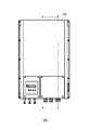
- FIG. 2A is a front view of the power conditioner 100.
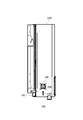
- FIG. FIG. 2B is a cross-sectional view of power conditioner 100 taken along line AA shown in FIG. 2A.
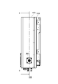
- FIG. 2C is a side view of the power conditioner 100 on the first side 120 a side.
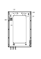
- FIG. 2D is a cross-sectional view of the power conditioner 100 taken along the line BB shown in FIG. 2C.
- the first temperature sensor 130 is fixed to the inner space side of the first side surface 120 a of the upper cover 120 near the air inlet 122 provided below the upper cover 120 in the state where the power conditioner 100 is installed.
- the first temperature sensor 130 has a sensor portion in contact with the inner space side of the first side surface 120a, and detects a first temperature corresponding to the temperature of the housing.
- the first temperature sensor 130 can detect a temperature relatively close to the outside air temperature by being provided in the vicinity of the air intake port 122 for taking in the outside air. Note that the installation position of the first temperature sensor 130 is not limited to the above position.
- the first temperature sensor 130 may be provided on the outer surface of the upper lid 120.
- the second temperature sensor 132 is provided inside the back base 110 via a second projection 104 provided in the vicinity of the exhaust port 114 provided above the back base 110 in the state where the power conditioner 100 is installed. It is fixed to the space side.
- the second temperature sensor 132 is disposed in the internal space without contacting the back base 110 and the upper lid 120, and detects a second temperature corresponding to the temperature of the internal space of the housing. .
- the installation position of the second temperature sensor 132 is not limited to the above position.
- the second temperature sensor 132 may be provided in an internal space in the vicinity of an electronic component such as a switching element having a relatively large amount of heat generation.
- the humidity sensor 134 is fixed to the upper first side surface 120 a side via the third protrusion 106 in a state where the power conditioner 100 of the back surface base 110 is installed.
- the humidity sensor 134 is disposed in the internal space without contacting the back base 110 and the upper lid 120, and detects the humidity of the internal space of the housing.
- the installation position of the humidity sensor 134 is not limited to the above position. Humidity sensor 134 may be provided below in the state where power conditioner 100 of back pedestal 110 was installed.
- the power conditioner 100 generates the first fan unit 200 or the first fan unit 200 based on the first temperature and the second temperature detected by the first temperature sensor 130 and the second temperature sensor 132 and the humidity detected by the humidity sensor 134. 2) Control the suction amount or the exhaust amount of the fan unit 300. This suppresses the occurrence of dew condensation on the housing.
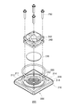
- FIG. 3A is an exploded perspective view of the first fan unit 200.
- FIG. FIG. 3B is a front view of the first fan unit 200 as viewed in the direction of the arrow indicated by reference numeral 202 in FIG. 3A.
- FIG. 3C is a cross-sectional view of the first fan unit 200 taken along line CC shown in FIG. 3B.
- the second fan unit 300 may have the same configuration as the first fan unit 200.
- the first fan unit 200 includes a frame 210, an O-ring 220, a waterproof and moisture-permeable filter 230, and a fan 240.
- the frame 210 has a circular opening 211 on the back side facing the front.
- the frame 210 also has a through hole 212 communicating with the opening 211.
- the through hole 212 allows air from the outside to pass through or air from the internal space to pass through.
- the through hole 212 also includes a plurality of fan-shaped through grooves, and also functions as a finger guard that prevents intrusion of human fingers, relatively large dust, insects, and the like.
- the frame 210 has a plurality of bolt holes 214 formed on the back side along the outer periphery of the opening 211.
- the plurality of bolt holes 214 are screwed with a plurality of bolts 250 for fixing the fan 240.
- the fan 240 has a plurality of bolt through holes 242 at its edge, and the plurality of bolts 250 fix the fan 240 and the frame 210 via the plurality of bolt through holes 242 and the plurality of bolt holes 214.
- the frame 210 has an annular groove 216 formed along the outer periphery of the opening 211 on the outer peripheral side of the plurality of bolt holes 214.
- O-ring 220 is disposed within annular groove 216 and surrounds opening 211.
- the O-ring 220 is a foreign matter such as water in the internal space of the housing via the air inlet 122 from the clearance between the rear surface of the frame 210 and the installation surface of the first fan unit 200 of the upper lid 120, that is, the first side surface 120a.
- the frame 210 also has a plurality of through holes 218 formed on the outer peripheral side of the annular groove 216. A plurality of bolts for fixing the first fan unit 200 to the first side surface 120 a of the upper lid 120 are inserted into the plurality of through holes 218.
- the frame 210 has a step portion 213 formed along the inner circumferential surface of the opening 211.
- the stepped portion 213 is an example of the peripheral portion of the through hole 212, and the edge of the waterproof and moisture-permeable filter 230 is disposed on the stepped portion 213.
- the filter 230 may be fixed to the frame 210 by heat welding the stepped portion 213 and the edge of the filter 230.
- the filter 230 may be fixed to the frame 210 by bonding the step portion 213 and the edge of the filter 230 with an adhesive.
- the waterproof and moisture permeable filter 230 is made of a material through which water vapor passes but not water.
- the filter 230 may be made of a porous membrane such as a tetrafluorinated ethylene resin porous membrane or a fluorocarbon resin porous membrane used for an internal pressure adjustment filter or the like.
- a porous membrane such as a tetrafluorinated ethylene resin porous membrane or a fluorocarbon resin porous membrane used for an internal pressure adjustment filter or the like.
- first fan unit 200 and the second fan unit 300 including the waterproof and moisture permeable filter are provided in the intake port and the exhaust port.
- a fan unit provided with a waterproof and moisture permeable filter may be provided in only one of the intake and exhaust ports. In this case, either the intake or the exhaust may be covered with a waterproof and moisture permeable filter.
- each of the intake and exhaust ports with a waterproof and moisture-permeable filter without providing a fan unit.
- the intake amount thereof may not be sufficiently obtained, and the ventilation of the internal space may not be sufficiently performed. Therefore, it is preferable to provide a fan unit provided with a waterproof and moisture permeable filter on at least one of the intake port and the exhaust port.
- the internal pressure of internal space can be raised by providing the fan unit provided with the waterproof and moisture-permeable filter only in an inlet port. By raising the internal pressure of the internal space, the relatively warm air in the internal space can be easily discharged to the outside through the waterproof and moisture permeable filter provided at the exhaust port.
- FIG. 4 is an exploded perspective view of the first fan unit 200 according to the first modification.
- the stepped portion 213 is provided on the rear surface side of the frame 210 than the first fan unit 200 shown in FIGS. 3A to 3C.
- the filter 230 is disposed between the frame 210 and the fan 240, and is held by the edge of the fan 240 and the peripheral edge of the through hole 212 of the frame 210, that is, the stepped portion 213.
- foreign matter such as water and dust can be prevented from entering the internal space of the housing from the gap between the step portion 213 and the peripheral portion of the filter 230 via the air inlet 122.
- FIG. 5 is an exploded perspective view of a first fan unit 200 according to a second modification.
- the first fan unit 200 according to the second modification is different from the first fan unit 200 shown in FIGS. 3A to 3C in that the frame 210 includes a main body 260 and a separating portion 262.
- the fan 240 is fixed to the main body 260.
- the separation part 262 is a hollow cylinder, and a through hole 212 functioning as a finger guard is formed at one end.
- the separation portion 262 has a convex portion 264 on the outer peripheral surface of the other end. Then, on the front side of the inner peripheral surface of the opening 211 of the main body portion 260, a fitting groove 219 which fits with the projection 264 is formed along the inner peripheral surface.
- the separation unit 262 is detachably fixed to the main body unit 260.
- the first fan unit 200 is fixed to the housing by configuring the frame 210 from the main body portion 260 and the separating portion 262 and making the separating portion 262 detachable with respect to the main body portion 260, The operations such as cleaning of the filter 230 and replacement of the filter 230 are facilitated.
- FIG. 6 shows a perspective view of the power conditioner 100 according to the second embodiment.
- the power conditioner 100 according to the second embodiment is the power conditioner 100 according to the first embodiment in that the first fan unit 200 is installed on the bottom surface of the recess 124 formed below the first side surface 120a. It is different from The intake port 122 is formed on the bottom of the recess 124.
- the first fan unit 200 in the recess 124, it is possible to prevent a part of the side surface of the power conditioner 100 from protruding. Therefore, it can prevent that the 1st fan unit 200 provided in the side of power conditioner 100 limits the installation place of power conditioner 100.
- FIG. 7 is a diagram showing functional blocks of a fan control device that performs fan control of the first fan unit 200 and the second fan unit 300, which the power conditioner 100 has.
- the fan control device includes a first temperature information acquisition unit 12, a second temperature information acquisition unit 14, a humidity information acquisition unit 16, a fan control unit 10, and a threshold information storage unit 18.
- the first temperature information acquisition unit 12 acquires, via the first temperature sensor 130, first temperature information indicating a first temperature corresponding to the temperature of the case having the back base 110 and the upper lid 120 that accommodates the electronic component. .
- the second temperature information acquisition unit 14 acquires, via the second temperature sensor 132, second temperature information indicating a second temperature corresponding to the temperature of the internal space of the housing.
- the humidity information acquisition unit 16 acquires humidity information indicating the humidity of the internal space of the housing via the humidity sensor 134.
- the fan control unit 10 may The air flow amount indicating the intake or exhaust amount of the first fan unit 200 or the second fan unit 300 provided at the exhaust port is increased.
- the fan control unit 10 may increase the amount of ventilation when the temperature difference is equal to or greater than the first threshold and the humidity indicated by the humidity information is equal to or greater than a predetermined second threshold.
- the threshold information holding unit 18 holds predetermined first and second threshold values.
- the first threshold and the second threshold cause the power conditioner 100 to operate under a plurality of conditions different in the environment of the temperature and humidity of the outside air, and under these conditions, dew condensation occurs in the power conditioner 100.
- the relationship between the temperature difference and the humidity may be recorded and determined in advance based on the recording result.
- the fan control unit 10 may stop the fan operation of the first fan unit 200 and the second fan unit 300 when the temperature difference is less than the first threshold.
- the fan control unit 10 detects in advance that the temperature difference is less than the first threshold in the fan operation of the first fan unit 200 and the second fan unit 300. It may be stopped after a predetermined time has elapsed.
- the fan control unit 10 gradually reduces the ventilation amount of the first fan unit 200 and the second fan unit 300, and the temperature difference is less than the first threshold.
- the fan operation of the first fan unit 200 and the second fan unit 300 may be stopped after a predetermined time has elapsed since detection.
- the fan control unit 10 decreases the ventilation amount of the first fan unit 200 and the second fan unit 300 by, for example, a predetermined amount or ratio, and then the temperature difference
- the fan operation of the first fan unit 200 and the second fan unit 300 may be stopped when it becomes less than the third threshold smaller than the first threshold.
- the threshold information holding unit 18 may hold the second threshold for each temperature difference.
- the fan control unit 10 refers to the second threshold corresponding to the temperature difference
- the humidity is equal to or more than the second threshold corresponding to the temperature difference
- the air flow rate of the one fan unit 200 or the second fan unit 300 may be increased.
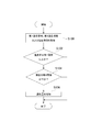
- FIG. 8 is a flowchart showing a fan control flow performed by the fan control device.
- the fan controller periodically executes a fan control flow.
- the first temperature information acquiring unit 12 acquires the first temperature information via the first temperature sensor 130, and the second temperature information acquiring unit acquires the second temperature information via the second temperature sensor 132. Further, the humidity information acquisition unit 16 acquires humidity information via the humidity sensor 134 (S100). Next, the fan control unit 10 calculates the temperature difference by subtracting the first temperature indicated by the first temperature information from the second temperature indicated by the second temperature information, and determines whether the temperature difference is equal to or greater than the first threshold. (S102). When the temperature difference is smaller than the first threshold as a result of the determination, the fan control unit 10 determines that the possibility of the occurrence of condensation is low, and ends the processing.
- the fan control unit 10 determines whether the humidity indicated by the humidity information is equal to or more than the second threshold (S104). As a result of the determination, if the humidity is smaller than the second threshold, the fan control unit 10 determines that the possibility of the occurrence of condensation is low, and ends the processing. As a result of the determination, if the humidity is equal to or higher than the second threshold, the fan control unit 10 determines that the possibility of condensation occurring is high, and the intake amount or the exhaust of the first fan unit 200 or the second fan unit 300 The aeration amount indicating the amount is increased (S106).
- the fan control unit 10 may increase the ventilation amount of the first fan unit 200 or the second fan unit 300 by increasing the fan rotational speed of the first fan unit 200 or the second fan unit 300.
- the fan control unit 10 operates the first fan unit 200 or the second fan unit 300 to operate the first fan unit 200.
- the air flow rate of the second fan unit 300 may be increased.
- the fan control unit 10 increases the ventilation amount of the first fan unit 200 or the second fan unit 300 when the temperature difference is the first threshold or more and the humidity is the second threshold or more. explained. However, the fan control unit 10 may increase the ventilation amount of the first fan unit 200 or the second fan unit 300 when the temperature difference is equal to or more than the first threshold regardless of the magnitude of the humidity.
- the fan control apparatus may be configured by installing a program that performs various processes related to the above-described fan control and causing the computer to execute the program. That is, the computer as the first temperature information acquisition unit 12, the second temperature information acquisition unit 14, the humidity information acquisition unit 16, the fan control unit 10, and the threshold information storage unit 18 by causing the computer to execute a program that performs fan control.
- the fan control device may be configured by causing
Landscapes
- Engineering & Computer Science (AREA)
- Microelectronics & Electronic Packaging (AREA)
- Mechanical Engineering (AREA)
- General Engineering & Computer Science (AREA)
- Physics & Mathematics (AREA)
- Thermal Sciences (AREA)
- Cooling Or The Like Of Electrical Apparatus (AREA)
Abstract
電子部品を収容する筐体を備える電気機器においては、筐体の内部への水分の侵入を防ぐことが要求されている。ファンユニットは、貫通口を有するフレームと、貫通口を覆う防水透湿性のフィルタと、フレームに固定され、貫通口およびフィルタを介して通気を行うファンとを備える。フィルタは、フレームに固着されてもよい。フィルタは、フレームとファンとの間に配置され、ファンの縁部と、フレームの貫通口の周縁部とにより狭持されてもよい。
Description
本発明は、ファンユニットおよびファンユニットを備える電気機器に関する。
特許文献1には、各種電気機器を収容する箱体本体の内部への塵埃の侵入を防ぐフィルタを備え、箱体本体の内部で発生する熱を箱体本体の外部に放出する放熱装置が開示されている。
特許文献1 特開2000-209717号公報
特許文献1 特開2000-209717号公報
電子部品を収容する筐体を備える電気機器においては、筐体の内部への水分の侵入を防ぐことが要求されている。
本発明に係るファンユニットは、貫通口を有するフレームと、貫通口を覆う防水透湿性のフィルタと、フレームに固定され、貫通口およびフィルタを介して通気を行うファンとを備える。
上記ファンユニットにおいて、フィルタは、フレームに固着されてもよい。フィルタは、フレームとファンとの間に配置され、ファンの縁部と、フレームの貫通口の周縁部とにより狭持されてもよい。フレームは、ファンが固定される本体部と、貫通口が形成された分離部と有し、分離部は、本体部に着脱可能に固定されてもよい。
本実施形態に係る電気機器は、吸気口を有し、電子部品を収容する筐体と、吸気口に設けられた上記ファンユニットである第1ファンユニットとを備える。
上記電気機器において、筐体は、第1側面に吸気口を有し、ファンユニットのフレームが、筐体の吸気口の周縁部に着脱可能に固定されてもよい。筐体は、第1側面に凹部を有し、吸気口は、凹部の底面に形成され、ファンユニットのフレームが、凹部の底面に着脱可能に固定されてもよい。
上記電気機器において、筐体は、第1側面の下方に吸気口を有し、背面の上方の第1側面に対向する第2側面側に排気口をさらに有してもよい。上記電気機器は、排気口を覆う防水透湿性のフィルタをさらに備えてもよい。上記電気機器は、排気口に設けられた上記ファンユニットである第2ファンユニットをさらに備えてもよい。
なお、上記の発明の概要は、本発明の必要な特徴の全てを列挙したものではない。また、これらの特徴群のサブコンビネーションもまた、発明となりうる。
以下、発明の実施の形態を通じて本発明を説明するが、以下の実施形態は請求の範囲にかかる発明を限定するものではない。また、実施形態の中で説明されている特徴の組み合わせの全てが発明の解決手段に必須であるとは限らない。
図1は、第1実施形態に係るパワーコンディショナ100の分解斜視図を示す。パワーコンディショナ100は、昇圧回路およびインバータを備える。昇圧回路およびインバータは、電子部品の一例である。パワーコンディショナ100は、太陽電池、燃料電池などの直流電源からの直流電圧を昇圧回路により昇圧し、昇圧された直流電圧をインバータにより交流電圧に変換して、負荷に供給する。または、パワーコンディショナ100は、交流電圧を系統電源に逆潮流する。
パワーコンディショナ100は、背面基台110、基板112、上蓋120、吸気用の第1ファンユニット200、排気用の第2ファンユニット300、第1温度センサ130、第2温度センサ132、湿度センサ134、冷却ダクト140、および冷却ファンユニット142を備える。背面基台110および上蓋120が電子部品を収容する筐体の一例である。背面基台110の一方の面には、基板112が設けられる。上蓋120は、背面基台110の一方の面を覆い、電子部品が収容される内部空間、つまり筐体の内部空間を形成する。
背面基台110の縁部には、縁部を囲繞するゴムなどの弾性材料からなる環状のパッキン111が配置されている。パッキン111は、背面基台110と上蓋120とに密着し、背面基台110と上蓋120との間から水などの異物が内部空間に侵入することを防止する。上蓋120は、パワーコンディショナ100が設置された状態において下方の上蓋120の第1側面120aに、通気口の一例である吸気口122を有する。背面基台110は、パワーコンディショナ100が設置された状態において上方で、かつ上蓋120の第1側面120aに対向する第2側面120b側に、通気口の一例である排気口114を有する。背面基台110と上蓋120とはパッキン111により密着しており、背面基台110と上蓋120とから構成される内部空間は、吸気口122および排気口114以外外部空間と連通している部分がない。つまり、内部空間は、吸気口122および排気口114以外において密閉空間である。
第1ファンユニット200は、吸気口122を覆うように吸気口122に設けられ、筐体の内部空間に外部の空気を吸引する。第2ファンユニット300は、排気口114を覆うように排気口114に設けられ、筐体の内部空間から外部へ空気を排気する。第1ファンユニット200および第2ファンユニット300が作動することにより、筐体の内部空間に外部の比較的低温な空気が取り込まれ、筐体の内部空間の比較的高温な空気が外部へ排出される。これにより、筐体の内部空間の空気が換気され、内部空間の温度の上昇および筐体に対する結露の発生を抑制できる。
基板112は、背面基台110の上面に設けられた複数の第1突起部102を介して固定される。基板112には、昇圧回路およびインバータを構成する複数のスイッチング素子など複数の電子部品が設けられる。また、基板112には、第1ファンユニット200および第2ファンユニット300のファン動作を制御するファン制御装置として機能するマイクロコンピュータが設けられる。冷却ダクト140は、背面基台110の背面上に固定され、基板112に設けられた複数の電子部品を冷却する。冷却ファンユニット142は、冷却ダクト140の最上流側、言い換えれば、パワーコンディショナ100が設置された状態で下方側に設けられる。冷却ファンユニット142は、冷却ダクト140に強制的に空気を供給し、冷却ダクト140を冷却する。これにより、基板112に設けられた複数の電子部品が間接的に冷却される。
図2Aは、パワーコンディショナ100の正面図である。図2Bは、パワーコンディショナ100の図2Aに示すA-A断面図である。図2Cは、パワーコンディショナ100の第1側面120a側の側面図である。図2Dは、パワーコンディショナ100の図2Cに示すB-B断面図である。
第1温度センサ130は、パワーコンディショナ100が設置された状態において上蓋120の下方に設けられた吸気口122の近傍で、かつ上蓋120の第1側面120aの内部空間側に固定される。第1温度センサ130は、センサ部分が第1側面120aの内部空間側に接触しており、筐体の温度に対応する第1温度を検出する。第1温度センサ130は、外気を取り込む吸気口122の近傍に設けられることで、外気温に比較的に近い温度を検出できる。なお、第1温度センサ130の設置位置は、上記の位置には限定されない。第1温度センサ130は、上蓋120の外表面に設けられてもよい。
第2温度センサ132は、パワーコンディショナ100が設置された状態において背面基台110の上方に設けられた排気口114の近傍に設けられた第2突起部104を介して背面基台110の内部空間側に固定される。第2温度センサ132は、センサ部分が背面基台110および上蓋120のいずれにも接触せずに内部空間内に配置されており、筐体の内部空間の温度に対応する第2温度を検出する。なお、第2温度センサ132の設置位置は、上記の位置には限定されない。第2温度センサ132は、発熱量が比較的多いスイッチング素子などの電子部品の近傍の内部空間内に設けられてもよい。
湿度センサ134は、背面基台110のパワーコンディショナ100が設置された状態で上方の第1側面120a側に、第3突起部106を介して固定される。湿度センサ134は、センサ部分が背面基台110および上蓋120のいずれにも接触せずに内部空間内に配置されており、筐体の内部空間の湿度を検出する。湿度センサ134の設置位置は、上記の位置には限定されない。湿度センサ134は、背面基台110のパワーコンディショナ100が設置された状態で下方に設けられてもよい。
パワーコンディショナ100は、第1温度センサ130および第2温度センサ132により検出された第1温度および第2温度と、湿度センサ134により検出された湿度とに基づいて、第1ファンユニット200または第2ファンユニット300の吸引量または排気量を制御する。これにより、筐体に対する結露の発生を抑制する。
図3Aは、第1ファンユニット200の分解斜視図である。図3Bは、図3Aの符号202で示す矢印方向から見た第1ファンユニット200の正面図である。図3Cは、第1ファンユニット200の図3Bに示すC-C断面図である。なお、第2ファンユニット300は、第1ファンユニット200と同一の構成でよい。
第1ファンユニット200は、フレーム210、Oリング220、防水透湿性のフィルタ230、およびファン240を備える。フレーム210は、正面に対向する裏面側に円形状の開口211を有する。また、フレーム210は、開口211から連通している貫通口212を有する。貫通口212は、外部からの空気を通過させ、または内部空間からの空気を通過させる。また、貫通口212は、扇状の複数の貫通溝を含み、人の指、比較的大きな塵埃、虫などの侵入を防ぐフィンガーガードとしても機能する。
さらに、フレーム210は、開口211の外周に沿って裏面側に形成された複数のボルト穴214を有する。複数のボルト穴214は、ファン240を固定するための複数のボルト250が螺合される。ファン240は、縁部に複数のボルト貫通孔242を有し、複数のボルト250は、複数のボルト貫通孔242および複数のボルト穴214を介して、ファン240とフレーム210とを固定する。
フレーム210は、複数のボルト穴214の外周側に、開口211の外周に沿って形成された環状溝216を有する。Oリング220は、環状溝216内に配置され、開口211を囲繞する。Oリング220は、フレーム210の裏面と上蓋120の第1ファンユニット200の設置面、つまり第1側面120aとの間の隙間から、吸気口122を介して筐体の内部空間に水などの異物が混入するのを防止する。
また、フレーム210は、環状溝216の外周側に形成された複数の貫通穴218を有する。複数の貫通穴218には、第1ファンユニット200を上蓋120の第1側面120aに固定するための複数のボルトが挿入される。
さらに、フレーム210は、開口211の内周面に沿って形成された段差部213を有する。段差部213は、貫通口212の周縁部の一例であり、段差部213上に、防水透湿性のフィルタ230の縁部が配置される。段差部213とフィルタ230の縁部とが熱溶着されることで、フィルタ230は、フレーム210に固着されてよい。また、段差部213とフィルタ230の縁部とが接着剤で接着されることで、フィルタ230は、フレーム210に固着されてよい。このように、フィルタ230がフレーム210に固着されることで、フィルタ230とフレーム210との間の隙間から、吸気口122を介して筐体の内部空間に水、塵埃などの異物が混入するのを防止できる。
防水透湿性のフィルタ230は、水蒸気は通過するが、水は通過しない素材で構成される。フィルタ230は、内圧調整用フィルタなどに用いられる四ふっ化エチレン樹脂多孔質膜、ふっ素樹脂多孔質膜などの多孔質膜で構成されてもよい。このようなフィルタ230により貫通口212が覆われることにより、貫通口212を介して、外部から筐体の内部空間に水、塵埃などの異物が混入することを防止できる。しかも、フィルタ230は、水蒸気、つまり空気を通過させるので、第1ファンユニット200は、吸気口122を介して外部の空気を筐体の内部空間に供給することができる。
なお、第1実施形態では、防水透湿性のフィルタを備えた第1ファンユニット200および第2ファンユニット300を吸気口および排気口に設ける例について説明した。しかし、防水透湿性のフィルタを備えたファンユニットは、吸気口および排気口のいずれか一方のみに設けられてもよい。この場合、吸気口および排気口のいずれか他方は、防水透湿性のフィルタで覆われてもよい。
また、ファンユニットを設けずに、吸気口および排気口のそれぞれを防水透湿性のフィルタで覆うことも考えられる。しかし、防水透湿性のフィルタを介して内部空間に外気を自然吸引する場合、その吸気量が十分に得られず、内部空間の換気が十分に行えない可能性がある。そこで、吸気口および排気口の少なくとも一方には、防水透湿性のフィルタを備えたファンユニットを設けることが好ましい。また、防水透湿性のフィルタを備えたファンユニットを吸気口のみに設けることで、内部空間の内圧を高めることができる。内部空間の内圧が高められることで、内部空間の比較的暖かい空気が、排気口に設けられた防水透湿性のフィルタを介して外部へ排出されやすくできる。
図4は、第1変形例に係る第1ファンユニット200の分解斜視図である。第1変形例に係る第1ファンユニット200は、段差部213が、図3A~図3Cに示す第1ファンユニット200よりフレーム210の裏面側に設けられている。そして、フィルタ230は、フレーム210とファン240との間に配置され、ファン240の縁部と、フレーム210の貫通口212の周縁部、つまり段差部213とにより狭持される。これにより、段差部213とフィルタ230の周縁部との間の隙間から吸気口122を介して、筐体の内部空間に、水、塵埃などの異物が混入することを防止できる。
図5は、第2変形例に係る第1ファンユニット200の分解斜視図である。第2変形例に係る第1ファンユニット200は、フレーム210が、本体部260と分離部262とから構成される点で、図3A~図3Cに示す第1ファンユニット200とは異なる。本体部260は、ファン240が固定される。分離部262は、中空状の円柱であり、一方の端部に、フィンガーガードとして機能する貫通口212が形成されている。また、分離部262は、他方の端部の外周面に凸部264を有する。そして、本体部260の開口211の内周面の正面側には、内周面に沿って、凸部264と嵌合する嵌合溝219が形成されている。
本体部260と分離部262とを固定する場合、分離部262の他方の端部を本体部260の開口211の正面側から挿入する。そして、分離部262を開口211の内周面に沿って回転させることにより凸部264を嵌合溝219にスライドさせながら嵌合させる。これにより、分離部262は本体部260に着脱可能に固定される。このように、フレーム210を本体部260と分離部262とから構成し、分離部262を本体部260に対して着脱可能にすることで、第1ファンユニット200を筐体に固定した後において、フィルタ230の清掃、フィルタ230の交換などの作業が容易になる。
図6は、第2実施形態に係るパワーコンディショナ100の斜視図を示す。第2実施形態に係るパワーコンディショナ100は、第1側面120aの下方に形成された凹部124の底面に第1ファンユニット200が設置されている点で、第1実施形態に係るパワーコンディショナ100と異なる。吸気口122は、凹部124の底面に形成されている。このように、凹部124に第1ファンユニット200が設置されることで、パワーコンディショナ100の側面の一部分が突出することを防止できる。よって、パワーコンディショナ100の側面に設けられる第1ファンユニット200が、パワーコンディショナ100の設置場所を制限するのを防止できる。
図7は、パワーコンディショナ100が備える、第1ファンユニット200および第2ファンユニット300のファン制御を行うファン制御装置の機能ブロックを示す図である。ファン制御装置は、第1温度情報取得部12、第2温度情報取得部14、湿度情報取得部16、ファン制御部10、および閾値情報保持部18を備える。
第1温度情報取得部12は、電子部品を収容する背面基台110および上蓋120を有する筐体の温度に対応する第1温度を示す第1温度情報を第1温度センサ130を介して取得する。第2温度情報取得部14は、筐体の内部空間の温度に対応する第2温度を示す第2温度情報を第2温度センサ132を介して取得する。湿度情報取得部16は、筐体の内部空間の湿度を示す湿度情報を湿度センサ134を介して取得する。
ファン制御部10は、第1温度情報に示される第1温度と第2温度情報に示される第2温度との温度差が予め定められた第1閾値以上の場合に、筐体の吸気口または排気口に設けられる第1ファンユニット200または第2ファンユニット300の吸気量または排気量を示す通気量を増加させる。ファン制御部10は、温度差が第1閾値以上で、かつ湿度情報が示す湿度が予め定められた第2閾値以上の場合に、通気量を増加させてもよい。閾値情報保持部18は、予め定められた第1閾値および第2閾値を保持する。
なお、第1閾値および第2閾値は、パワーコンディショナ100を外気の温度および湿度の環境が異なる複数の条件化で動作させ、それらの条件下で、パワーコンディショナ100に結露が発生する場合の温度差および湿度との関係を記録し、その記録結果に基づいて予め定めればよい。
また、ファン制御部10は、温度差が第1閾値未満の場合、第1ファンユニット200および第2ファンユニット300のファン動作を停止させてもよい。あるいは、ファン制御部10は、温度差が第1閾値未満の場合、第1ファンユニット200および第2ファンユニット300のファン動作を、温度差が第1閾値未満であることを検知してから予め定められた時間経過後に、停止させてもよい。さらに、ファン制御部10は、温度差が第1閾値未満の場合、第1ファンユニット200および第2ファンユニット300の通気量を徐々に減少させて、温度差が第1閾値未満であることを検知してから予め定められた時間経過後に、第1ファンユニット200および第2ファンユニット300のファン動作を停止させてもよい。また、ファン制御部10は、温度差が第1閾値未満の場合、第1ファンユニット200および第2ファンユニット300の通気量を例えば予め定められた量または割合だけ減少させた後、温度差が第1閾値より小さい第3閾値未満になった場合に、第1ファンユニット200および第2ファンユニット300のファン動作を停止させてもよい。
また、閾値情報保持部18は、温度差の大きさごとに第2閾値を保持してよい。この場合、ファン制御部10は、温度差が第1閾値以上の場合、その温度差に対応する第2閾値を参照して、湿度がその温度差に対応する第2閾値以上の場合に、第1ファンユニット200または第2ファンユニット300の通気量を増加させてもよい。
図8は、ファン制御装置が実行するファン制御フローを示すフローチャートである。ファン制御装置は、ファン制御フローを周期的に実行する。
第1温度情報取得部12が第1温度センサ130を介して第1温度情報を取得し、第2温度情報取得部が第2温度センサ132を介して第2温度情報を取得する。さらに、湿度情報取得部16が湿度センサ134を介して湿度情報を取得する(S100)。次いで、ファン制御部10は、第1温度情報が示す第1温度を、第2温度情報が示す第2温度から減算することで温度差を算出し、温度差が第1閾値以上か否か判定する(S102)。判定の結果、温度差が第1閾値より小さい場合には、ファン制御部10は、結露が発生する可能性は低いと判断して、処理を終了する。
一方、温度差が第1閾値以上の場合には、ファン制御部10は、湿度情報が示す湿度が第2閾値以上か否かを判定する(S104)。判定の結果、湿度が第2閾値より小さい場合には、ファン制御部10は、結露が発生する可能性は低いと判断して、処理を終了する。判定の結果、湿度が第2閾値以上の場合には、ファン制御部10は、結露が発生する可能性が高いと判断して、第1ファンユニット200または第2ファンユニット300の吸気量または排気量を示す通気量を増加させる(S106)。
なお、ファン制御部10は、第1ファンユニット200または第2ファンユニット300のファン回転数を増加させることで、第1ファンユニット200または第2ファンユニット300の通気量を増加させてもよい。また、第1ファンユニット200または第2ファンユニット300が停止している場合には、ファン制御部10は、第1ファンユニット200または第2ファンユニット300を作動させることで、第1ファンユニット200または第2ファンユニット300の通気量を増加させてもよい。
また、上記では、ファン制御部10は、温度差が第1閾値以上で、かつ湿度が第2閾値以上の場合に、第1ファンユニット200または第2ファンユニット300の通気量を増加させる例について説明した。しかし、ファン制御部10は、湿度の大きさに関わらず、温度差が第1閾値以上の場合に、第1ファンユニット200または第2ファンユニット300の通気量を増加させてもよい。
なお、ファン制御装置は、上記のファン制御に関わる各種処理を行うプログラムをインストールし、このプログラムをコンピュータに実行させることで、構成してもよい。つまり、コンピュータにファン制御を行うプログラムを実行させることにより、第1温度情報取得部12、第2温度情報取得部14、湿度情報取得部16、ファン制御部10、および閾値情報保持部18としてコンピュータを機能させることで、ファン制御装置を構成してもよい。
以上、本発明を実施の形態を用いて説明したが、本発明の技術的範囲は上記実施の形態に記載の範囲には限定されない。上記実施の形態に、多様な変更または改良を加えることが可能であることが当業者に明らかである。その様な変更または改良を加えた形態も本発明の技術的範囲に含まれ得ることが、請求の範囲の記載から明らかである。
請求の範囲、明細書、および図面中において示した装置、システム、プログラム、および方法における動作、手順、ステップ、および段階等の各処理の実行順序は、特段「より前に」、「先立って」等と明示しておらず、また、前の処理の出力を後の処理で用いるのでない限り、任意の順序で実現しうることに留意すべきである。請求の範囲、明細書、および図面中の動作フローに関して、便宜上「まず、」、「次に、」等を用いて説明したとしても、この順で実施することが必須であることを意味するものではない。
10 ファン制御部
12 第1温度情報取得部
14 第2温度情報取得部
16 湿度情報取得部
18 閾値情報保持部
100 パワーコンディショナ
110 背面基台
112 基板
114 排気口
120 上蓋
122 吸気口
130 第1温度センサ
132 第2温度センサ
134 湿度センサ
200 第1ファンユニット
210 フレーム
212 貫通口
230 フィルタ
240 ファン
260 本体部
262 分離部
300 第2ファンユニット
12 第1温度情報取得部
14 第2温度情報取得部
16 湿度情報取得部
18 閾値情報保持部
100 パワーコンディショナ
110 背面基台
112 基板
114 排気口
120 上蓋
122 吸気口
130 第1温度センサ
132 第2温度センサ
134 湿度センサ
200 第1ファンユニット
210 フレーム
212 貫通口
230 フィルタ
240 ファン
260 本体部
262 分離部
300 第2ファンユニット
Claims (10)
- 貫通口を有するフレームと、
前記貫通口を覆う防水透湿性のフィルタと、
前記フレームに固定され、前記貫通口および前記フィルタを介して通気を行うファンと
を備えるファンユニット。 - 前記フィルタは、前記フレームに固着される請求項1に記載のファンユニット。
- 前記フィルタは、前記フレームと前記ファンとの間に配置され、前記ファンの縁部と、前記フレームの前記貫通口の周縁部とにより狭持される請求項1または請求項2に記載のファンユニット。
- 前記フレームは、前記ファンが固定される本体部と、前記貫通口が形成された分離部と有し、
分離部は、前記本体部に着脱可能に固定される請求項1から請求項3のいずれか1つに記載のファンユニット。 - 吸気口を有し、電子部品を収容する筐体と、
請求項1から請求項4のいずれか1つに記載のファンユニットである前記吸気口に設けられた第1ファンユニットと
を備える電気機器。 - 前記筐体は、第1側面に前記吸気口を有し、
前記ファンユニットの前記フレームが、前記筐体の前記吸気口の周縁部に着脱可能に固定される請求項5に記載の電気機器。 - 前記筐体は、前記第1側面に凹部を有し、
前記吸気口は、前記凹部の底面に形成され、
前記ファンユニットの前記フレームが、前記凹部の前記底面に着脱可能に固定される請求項6に記載の電気機器。 - 前記筐体は、前記第1側面の下方に前記吸気口を有し、背面の上方の前記第1側面に対向する第2側面側に排気口をさらに有する請求項6または請求項7に記載の電気機器。
- 前記排気口を覆う防水透湿性のフィルタをさらに備える請求項8に記載の電気機器。
- 請求項1から請求項4のいずれか1つに記載のファンユニットである第2ファンユニットをさらに備え、
前記第2ファンユニットは、前記排気口に設けられる請求項8に記載の電気機器。
Applications Claiming Priority (2)
| Application Number | Priority Date | Filing Date | Title |
|---|---|---|---|
| JP2012057794A JP2013191773A (ja) | 2012-03-14 | 2012-03-14 | ファンユニット、および電気機器 |
| JP2012-057794 | 2012-03-14 |
Publications (1)
| Publication Number | Publication Date |
|---|---|
| WO2013136642A1 true WO2013136642A1 (ja) | 2013-09-19 |
Family
ID=49160595
Family Applications (1)
| Application Number | Title | Priority Date | Filing Date |
|---|---|---|---|
| PCT/JP2013/000167 Ceased WO2013136642A1 (ja) | 2012-03-14 | 2013-01-16 | ファンユニット、および電気機器 |
Country Status (2)
| Country | Link |
|---|---|
| JP (1) | JP2013191773A (ja) |
| WO (1) | WO2013136642A1 (ja) |
Cited By (3)
| Publication number | Priority date | Publication date | Assignee | Title |
|---|---|---|---|---|
| WO2019200511A1 (en) * | 2018-04-16 | 2019-10-24 | Telefonaktiebolaget Lm Ericsson (Publ) | Vent filter and radio remote unit |
| DE102018211797B4 (de) | 2017-07-18 | 2024-04-11 | Denso Corporation | Elektronische vorrichtung |
| US20240384731A1 (en) * | 2021-03-05 | 2024-11-21 | Spectronik Pte. Ltd. | Mounting device for a fan unit |
Families Citing this family (3)
| Publication number | Priority date | Publication date | Assignee | Title |
|---|---|---|---|---|
| JP6981050B2 (ja) * | 2017-06-05 | 2021-12-15 | 株式会社デンソー | 電子装置 |
| JP6907724B2 (ja) | 2017-06-05 | 2021-07-21 | 株式会社デンソー | 電子装置 |
| KR102546724B1 (ko) * | 2021-05-06 | 2023-06-23 | 주식회사 송백이엔에스 | 방수 투습 벤트부가 적용된 바닥 신호등 장치 |
Citations (5)
| Publication number | Priority date | Publication date | Assignee | Title |
|---|---|---|---|---|
| JPH0614833U (ja) * | 1990-12-17 | 1994-02-25 | 河村電器産業株式会社 | 箱体用換気ユニット |
| JP2001168543A (ja) * | 1999-12-09 | 2001-06-22 | Nitto Denko Corp | 通気筐体 |
| JP2003273558A (ja) * | 2002-03-19 | 2003-09-26 | Sony Corp | 冷却装置および冷却装置を有する電子機器 |
| JP2006269791A (ja) * | 2005-03-24 | 2006-10-05 | Dkk Toa Corp | 取付部材、圧力調整部材及び水密筐体 |
| JP2006329507A (ja) * | 2005-05-25 | 2006-12-07 | Nitto Electric Works Ltd | 換気扇装置 |
Family Cites Families (1)
| Publication number | Priority date | Publication date | Assignee | Title |
|---|---|---|---|---|
| TWM387462U (en) * | 2010-04-19 | 2010-08-21 | Lite On Technology Corp | Ventilating and waterproof power converter |
-
2012
- 2012-03-14 JP JP2012057794A patent/JP2013191773A/ja active Pending
-
2013
- 2013-01-16 WO PCT/JP2013/000167 patent/WO2013136642A1/ja not_active Ceased
Patent Citations (5)
| Publication number | Priority date | Publication date | Assignee | Title |
|---|---|---|---|---|
| JPH0614833U (ja) * | 1990-12-17 | 1994-02-25 | 河村電器産業株式会社 | 箱体用換気ユニット |
| JP2001168543A (ja) * | 1999-12-09 | 2001-06-22 | Nitto Denko Corp | 通気筐体 |
| JP2003273558A (ja) * | 2002-03-19 | 2003-09-26 | Sony Corp | 冷却装置および冷却装置を有する電子機器 |
| JP2006269791A (ja) * | 2005-03-24 | 2006-10-05 | Dkk Toa Corp | 取付部材、圧力調整部材及び水密筐体 |
| JP2006329507A (ja) * | 2005-05-25 | 2006-12-07 | Nitto Electric Works Ltd | 換気扇装置 |
Cited By (4)
| Publication number | Priority date | Publication date | Assignee | Title |
|---|---|---|---|---|
| DE102018211797B4 (de) | 2017-07-18 | 2024-04-11 | Denso Corporation | Elektronische vorrichtung |
| WO2019200511A1 (en) * | 2018-04-16 | 2019-10-24 | Telefonaktiebolaget Lm Ericsson (Publ) | Vent filter and radio remote unit |
| US11110381B2 (en) | 2018-04-16 | 2021-09-07 | Telefonaktiebolaget Lm Ericsson (Publ) | Vent filter and radio remote unit |
| US20240384731A1 (en) * | 2021-03-05 | 2024-11-21 | Spectronik Pte. Ltd. | Mounting device for a fan unit |
Also Published As
| Publication number | Publication date |
|---|---|
| JP2013191773A (ja) | 2013-09-26 |
Similar Documents
| Publication | Publication Date | Title |
|---|---|---|
| WO2013136641A1 (ja) | 電気機器、コンピュータ読取可能な記録媒体、およびファン制御方法 | |
| WO2013136642A1 (ja) | ファンユニット、および電気機器 | |
| CN101815874B (zh) | 风扇马达单元 | |
| CN102860148B (zh) | 风扇和过滤器单元 | |
| WO2016000413A1 (zh) | 一种空气处理系统的顶盖及空气处理系统 | |
| US9667115B2 (en) | Electronic housing for an electric motor with protection against accidental contact | |
| TW201434273A (zh) | 具有通汽口之電子裝置及其外殼 | |
| CN102428324A (zh) | 送风装置和离子产生装置 | |
| CN110742312A (zh) | 电子烟的供电装置及电子烟 | |
| WO2016173188A1 (zh) | 一种带挡雨板的电机 | |
| CN103797608A (zh) | 干燥装置以及具有该种干燥装置的电池系统和机动车 | |
| JP5762111B2 (ja) | モータ保持構造及び電気機器 | |
| KR20170044558A (ko) | 가습공기청정기 | |
| KR20170044553A (ko) | 가습공기청정기 | |
| WO2016031782A1 (ja) | 空気清浄機 | |
| CN213371605U (zh) | 一种食品加工机 | |
| KR20170044557A (ko) | 가습공기청정기 | |
| CN217363474U (zh) | 一种上盖,电动车控制器壳体及电动车控制器 | |
| US20100054920A1 (en) | Fan assembly | |
| KR20170044552A (ko) | 가습공기청정기 | |
| CN101614223B (zh) | 风扇组合 | |
| JP3683719B2 (ja) | 電気掃除機 | |
| KR20170044559A (ko) | 가습공기청정기 | |
| JP2018140370A (ja) | 吸着ユニット及び空気清浄機 | |
| KR20170044550A (ko) | 가습공기청정기 |
Legal Events
| Date | Code | Title | Description |
|---|---|---|---|
| 121 | Ep: the epo has been informed by wipo that ep was designated in this application |
Ref document number: 13761706 Country of ref document: EP Kind code of ref document: A1 |
|
| NENP | Non-entry into the national phase |
Ref country code: DE |
|
| 122 | Ep: pct application non-entry in european phase |
Ref document number: 13761706 Country of ref document: EP Kind code of ref document: A1 |