WO2013136459A1 - Dispositif pour la culture des plantes - Google Patents
Dispositif pour la culture des plantes Download PDFInfo
- Publication number
- WO2013136459A1 WO2013136459A1 PCT/JP2012/056498 JP2012056498W WO2013136459A1 WO 2013136459 A1 WO2013136459 A1 WO 2013136459A1 JP 2012056498 W JP2012056498 W JP 2012056498W WO 2013136459 A1 WO2013136459 A1 WO 2013136459A1
- Authority
- WO
- WIPO (PCT)
- Prior art keywords
- nozzle
- cultivation box
- cultivation
- plant
- mist
- Prior art date
Links
Images


Classifications
-
- A—HUMAN NECESSITIES
- A01—AGRICULTURE; FORESTRY; ANIMAL HUSBANDRY; HUNTING; TRAPPING; FISHING
- A01G—HORTICULTURE; CULTIVATION OF VEGETABLES, FLOWERS, RICE, FRUIT, VINES, HOPS OR SEAWEED; FORESTRY; WATERING
- A01G31/00—Soilless cultivation, e.g. hydroponics
-
- B—PERFORMING OPERATIONS; TRANSPORTING
- B05—SPRAYING OR ATOMISING IN GENERAL; APPLYING FLUENT MATERIALS TO SURFACES, IN GENERAL
- B05B—SPRAYING APPARATUS; ATOMISING APPARATUS; NOZZLES
- B05B1/00—Nozzles, spray heads or other outlets, with or without auxiliary devices such as valves, heating means
- B05B1/26—Nozzles, spray heads or other outlets, with or without auxiliary devices such as valves, heating means with means for mechanically breaking-up or deflecting the jet after discharge, e.g. with fixed deflectors; Breaking-up the discharged liquid or other fluent material by impinging jets
- B05B1/262—Nozzles, spray heads or other outlets, with or without auxiliary devices such as valves, heating means with means for mechanically breaking-up or deflecting the jet after discharge, e.g. with fixed deflectors; Breaking-up the discharged liquid or other fluent material by impinging jets with fixed deflectors
- B05B1/265—Nozzles, spray heads or other outlets, with or without auxiliary devices such as valves, heating means with means for mechanically breaking-up or deflecting the jet after discharge, e.g. with fixed deflectors; Breaking-up the discharged liquid or other fluent material by impinging jets with fixed deflectors the liquid or other fluent material being symmetrically deflected about the axis of the nozzle
Definitions
- the present invention relates to a plant cultivation device, and more specifically, spraying under optimum conditions from an optimum nozzle in fog cultivation where a nutrient solution is sprayed from the nozzle onto the root zone of the cultivated plant.
- Patent Document 1 a fog containing nutrient solution is generated using a humidifier. Since the amount of fine mist generated from this humidifier is too small, it remains in the hobby of horticulture and is not suitable for actual business.
- the nutrient solution is sprayed from the nozzle, but if the particle size of the sprayed nutrient solution is large, it is easy to fall as droplets, the time to stay in the plant rhizosphere space is shortened, and the nutrient solution absorption rate becomes worse. Therefore, by reducing the particle size of the nutrient solution and making dry fog with an average particle size of 10 ⁇ m or less, the residence time becomes longer, and the nutrient solution absorption rate to the plant can be increased. Can be lowered.
- a nozzle that sprays dry fog having a particle size of less than 5 ⁇ m usually has an extremely small amount of spray per hour.
- the spray amount of the nutrient solution directly affects the growth of the plant, and the number of plants that can be cultivated with one nozzle is drastically reduced. And the amount of nutrient solution which a plant requires increases with growth, and the more the number of plants increases, the more spraying is required. Therefore, when a nozzle that sprays dry fog having a particle size of less than 5 ⁇ m is used for plant cultivation, a large number of nozzles are required, which causes a problem that the facility and the operation cost become high and farming becomes impossible.
- the residence time of the fine particles that are sprayed and containing nutrient solution can be increased, increasing the absorption rate to the plant and increasing the fertilizer cost
- waste water treatment is not necessary because the number of droplets falling is small.
- the nozzle that injects the dry fog is likely to be clogged, there is a problem that maintenance work is required and the running cost is increased.
- the average particle size is less than 5 ⁇ m, the amount of spraying is extremely reduced, which increases the number of nozzles required and increases the equipment cost and running cost.
- the present invention has been made in view of the above problems, and in fog cultivation, it is possible to supply a nutrient solution from a nozzle under conditions suitable for a cultivated plant, and to enable farming using a plant cultivation apparatus. Yes.
- the present invention sprays a nutrient solution as a mist having an average particle diameter of 5 to 10 ⁇ m as measured by a laser method in a hollow cultivation box in which the root of a cultivated plant hangs down.
- a nozzle that is 2-3 liters / hour
- the number and arrangement position of the nozzles are set according to the shape of the cultivation box so that the inner volume of the cultivation box is a maximum of 6 m 3 per nozzle, and the cultivation box is sprayed from the nozzle.
- a plant cultivation device characterized by comprising a control device for controlling the nozzle so that the humidity of the inside becomes 95% or more and 100% or less.
- the nozzle used in the present invention is a nozzle that can spray the nutrient solution as dry fog having an average particle size of 5 to 10 ⁇ m.
- the average particle diameter is measured at a position 30 cm from the nozzle nozzle using a laser diffraction method.
- the reason why the average particle size is 10 ⁇ m or less is that the dwell time of the fog of the dry fog nutrient solution can be increased to bring the inside of the cultivation box into a near-saturated state.
- the average particle size exceeds 10 ⁇ m, the particles easily fall, and there is an adhesion agglomeration effect between the particles, the particle size is enlarged and the fall is promoted, and it becomes difficult to float in the air as mist.
- the smaller the particle size that is, the dry fog of 10 ⁇ m or less, it is possible to expand the space in which the humidity can be maintained at 95% or more.
- the lower limit of the average particle size is set to 5 ⁇ m or more because nozzles less than 5 ⁇ m are likely to be clogged, and the amount of spray from one nozzle is extremely small, so the nozzle 1 in the cultivation box The volume per piece becomes small. Therefore, the number of necessary nozzles installed in the cultivation box increases, and the equipment cost and running cost increase.
- the nozzle for spraying the dry fog is a nozzle capable of spraying dry fog having an average particle diameter of 5 to 10 ⁇ m at a spray amount of 2 to 3 liters / hour.
- the volume per nozzle can be increased to a maximum of 6 m 3 .
- the humidity in the space can be made 95-100% by dry fog from the nozzle, which is sufficient for the roots of cultivated plants planted in the set space.
- a nutrient solution can be supplied.
- the humidity may be 97% or more, and the set humidity may be changed to 97% or more according to the growth of cultivated plants.
- the maximum volume per nozzle is 6 m 3 indicates that the flow rate of the mist sprayed from the nozzle needs to be 0.2 m / s or more, and if it is less than this flow rate, the plant does not grow greatly. by. If it exceeds 6 m 3 , the flow rate of the mist sprayed from the nozzle is less than 0.2 m / s, so the maximum volume per nozzle is 6 m 3 .
- the control device is configured such that the humidity in the cultivation box is 95% or more based on data obtained by measuring in advance the correlation between the spray amount and flow rate of the mist from the nozzle, the volume of the cultivation box, and the humidity in the cultivation box.
- the nozzle is controlled by setting the spray amount from the nozzle so as to be 100% or less.
- the plant cultivation apparatus of the present invention is intended for farming, for example, a large cultivation box having a length of 6 m, a width of 1 m, and a height of 0.4 m is suitably used as the most economical cultivation box.
- the spray amount is 2 to 3 so that dry fog having an average particle diameter of 5 to 10 ⁇ m is uniformly filled in the hollow of this large cultivation box to a humidity of 95% or more and the 95% or more can be maintained.
- a liter / hour nozzle is used, and the number of nozzles installed can be reduced by using the nozzle.
- a two-fluid nozzle is used as the nozzle, and the gas supply path and the liquid supply path of the nozzle body are not provided with an orifice with a reduced channel cross-sectional area in the middle of the supply path, and the channel cross-sectional area is directed toward the nozzle side.
- the fluid pressure is reduced to increase the fluid pressure, and the gas supply path and the liquid supply path are joined at a gas-liquid mixing portion facing a mixed fluid injection hole (a nozzle) that opens at the tip of the nozzle body, and
- One J-shaped collision pin protrudes from the outer surface on the tip side of the nozzle body. The collision pin extends from the tip of the leg to the mixed fluid injection hole.
- An ultrasonic two-fluid nozzle that includes a collision portion that turns back toward the surface, the mixed fluid ejected from the mixed fluid ejection hole collides with the collision portion, generates ultrasonic waves, and droplets collided with the ultrasonic waves are atomized Is the driving source.
- the two-fluid nozzle used in the plant cultivation apparatus of the present invention can reduce the average particle diameter of the mist mixed with the nutrient solution and air to 5 to 10 ⁇ m and increase the spray amount to 2 to 3 liters / hour. Further, the two-fluid nozzle has a structure in which no orifice is provided as described above, so that clogging is less likely to occur, and the average particle size is obtained by colliding the mist sprayed from the nozzle body with a collision pin. A dry fog having a diameter of 5 to 10 ⁇ m can be obtained.
- the flow path is cut off toward the gas-liquid mixing section facing the nozzle nozzle. Since the area is reduced, the fluid pressure can be gradually increased. Thus, since the transverse orifice is not provided in the flow path, the flow path sandwiching the orifice does not expand, and there is no portion where turbulence occurs. As a result, it is possible to reduce or prevent foreign substances in the fluid from adhering to the inner peripheral surfaces of the gas supply path and the liquid supply path and depositing them to cause clogging.
- the two-fluid nozzle has a collision pin projecting from the nozzle
- the mixed fluid ejected from the nozzle nozzle is caused to collide with the collision surface of the collision pin to generate an ultrasonic vibration and is ejected.
- a droplet can be refined.
- the cross-sectional shape perpendicular to the axis of the leg of the collision pin is a streamline shape or a triangle that converges in the direction of the central axis of the nozzle, and the diameter is increased toward the folded tip of the collision pin. Is preferred. With this configuration, it is possible to reduce or prevent droplets from adhering to the leg portion and the collision portion of the collision pin.
- the said control apparatus used with the plant cultivation apparatus of this invention is based on the data which measured beforehand the correlation with the spraying quantity and flow rate of the fog from the said nozzle, the volume of the said cultivation box, and the humidity in the said cultivation box.
- the mist spray amount is set and supplied so that the humidity range is within the cultivation box,
- the said nozzle is installed in the inner surface of the one end side of the longitudinal direction of the said cultivation box, it sprays toward the other end side, a rocking
- an inclined plate inclined upward toward the side is arranged with a gap from the inner surface of the cultivation box.
- a fan is installed on the inner surface of the other end opposite to the nozzle installation side, and after spraying from the nozzle flows to the other end along the upper surface of the inclined plate, it faces downward at the other end. It is preferable to change the direction and circulate along the lower surface of the inclined plate. That is, when the cultivation box is a large box, it is necessary to give a required flow rate to the sprayed mist in order to uniformly fill the mist inside the box. Therefore, when the cultivation box is large, a fan is installed and a required flow rate is given to the mist for measurement. In addition, a fan is not essential if the cultivation box can be filled with mist evenly at the flow rate of the mist supplied by the cultivation box in a relatively small size. Even if the cultivation box is large, a fan is not essential if the number of nozzles is increased.
- the upper surface opening of the cultivation box is closed with a support material that float-supports the boundary between the root portion and the ground portion of the cultivated plant to form the hollow portion. It is preferable that spraying from the nozzle be performed intermittently or continuously by automatic or manual switching operation. Furthermore, it is preferable that the nutrient solution remaining at the bottom of the cultivation box is collected in a nutrient solution tank and mixed with a new nutrient solution to form a resprayed nutrient solution.
- fruit vegetables such as basil
- fruit vegetables such as tomato, strawberry, melon, mango
- root vegetables such as potato, radish, beans
- fog is generated using a nozzle capable of spraying dry fog having an average particle size of 5 to 10 ⁇ m at a spray amount of 2 to 3 liters / hour into the hollow portion of the cultivation box that hangs the root of the cultivated plant. Since cultivation is performed, the volume per nozzle in the cultivation box can be maintained at 95% humidity while increasing the maximum volume to 6 m 3 . Therefore, since dense planting and continuous cropping are possible, a cultivated plant can be grown rapidly in large quantities, and it can be used suitably as a cultivation apparatus for farming.
- (A) is sectional drawing which shows an example of the cultivation box of the plant cultivation apparatus of embodiment of this invention
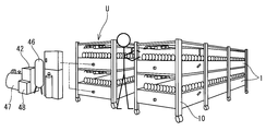
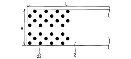
- (B) is an expanded sectional view of the BB line of (A). It is a perspective view of the whole plant cultivation apparatus. It is a top view which shows the support material which arrange
- (A) to (C) are tables showing the results of measurement under different measurement conditions. It is a graph which shows the result of the said measurement test.
- the plant cultivation apparatus includes a rectangular cultivation box 1 having an upper surface opening.
- the size of each cultivation box 1 is such that a large number of cultivated plants P can be cultivated at regular intervals in the length direction L and the width direction W.
- the cultivation box 1 of the present embodiment has a length L of 6 m, a width W of 1 m, and a height H of 0.4 m. Therefore, the volume of the hollow portion of the cultivation box 1 is 2.4 m 3 .
- the plurality of cultivation boxes 1 are mounted in a plurality of stages on the mounting frame 10 to form one unit U, and a plurality of units are installed in a plant factory, a greenhouse, or outdoors. In addition, you may install in a garden or a veranda at home.
- the upper surface opening 1 h of the cultivation box 1 is closed with the support material 2 to form a substantially sealed hollow portion 3 inside the cultivation box 1.
- the support material 2 includes a substrate 20 made of styrene foam and a heat shield 21 fixed to the upper surface of the substrate 20.
- planting holes 22 are provided in the support material 2 in a staggered arrangement at a necessary interval, and cultivated plants P are planted in the planting holes 22 as shown in FIG.
- the sponge material 4 is pushed in and supported by the support material 2, and the root portion Pr of the cultivated plant P float-supported by the support material 2 is suspended in the hollow portion 3.
- 168 planting holes 22 are provided in the support material 2 of one cultivation box 1 so that 168 plants are planted.
- the planting holes 22 provided in advance in the support material 2 are different in the spacing between the planting holes 22 by changing the arrangement in the length direction L and the width direction W according to the type of plant and the size at the time of growth. I am letting.
- the volume of the cultivation box 1 is a substantially central position in the width direction W of the inner surface of the left wall 1b in FIG. 1 surrounding the hollow portion 3 of 2.4 m 3, attach the nozzle 5 for a single spray.
- the nozzle 5 is a two-fluid nozzle shown in FIGS. 5 and 6, and a spray nozzle capable of spraying dry fog mist M having an average particle size of 5 to 10 ⁇ m by mixing a nutrient solution obtained by diluting fertilizer with water at a required magnification with air. It is.
- the nozzle 5 connects a pressurized air supply pipe 7b and a nutrient solution supply pipe 7a composed of a suction tube.
- the nutrient solution is sucked from the nutrient solution supply tube 7a by the air introduced from the pressure air supply tube 7b, mixed inside the nozzle body 5a, and sprayed from the nozzle 5b provided at the tip of the nozzle body 5a.
- the structure has an external collision member composed of a collision pin 51 that generates ultrasonic vibrations when the spray from the nozzles collides with the outside of the position opposite to the nozzle holes 5b, and the particles are further refined by ultrasonic vibrations.
- the two-fluid nozzle 5 is a nozzle capable of spraying ultrafine mist having an average particle diameter of 5 to 10 ⁇ m at 2 to 3 liters / hour.
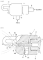
- the nozzle 5 includes an inner cylinder 52 and an outer cylinder 53 having a central axis O as an axis, a hollow portion of the inner cylinder 52 is used as a gas supply path 54, and a liquid supply path 55 is provided between the inner cylinder 52 and the outer cylinder 53. Yes.
- One end opening of the inner cylinder 52 is used as an inlet of the gas supply path 54, and a gas injection hole 54b is provided at the other end. As shown in FIG.
- the flow passage cross-sectional area is reduced from the inlet to the gas injection hole 54b, and the pressure of the air A flowing in at the required pressure is increased. No orifice is provided in the gas supply path 54 up to the injection hole 54b.
- a liquid Q composed of a nutrient solution obtained by diluting fertilizer with water is introduced into a liquid supply path 55 provided between the inner cylinder 52 and the outer cylinder 53 from an inlet 55c opened on the outer peripheral surface of the outer cylinder 53.
- the channel cross-sectional area in the direction perpendicular to the axis of the annular liquid channel 55 is gradually reduced toward the gas-liquid mixing part 58 on the tip side, and no orifice is provided in the middle of the channel of the liquid supply channel 55.
- the liquid inlet may not be provided on the outer peripheral surface of the outer cylinder, but may be provided at the tip in the axial direction of the outer cylinder.
- a nozzle hole 5b including a mixed fluid injection hole is provided at the center of the tip of the outer cylinder 53.
- the center line of the nozzle hole 5b and the gas injection hole 54b are positioned on the center axis O.
- a required dimension is formed in the axial direction between the nozzle hole 5b and the gas injection hole 54b, and this space portion is used as the gas-liquid mixing portion 58.
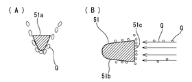
- a single J-shaped collision pin 51 protrudes from the outer surface on the front end side of the outer cylinder 53, and the mixed fluid and the jet mixed fluid in which the mixed fluid jetted from the nozzle 5b is repelled on the pin 51 for collision. Are caused to generate ultrasonic vibrations, and the droplets of the mixed fluid ejected by the ultrasonic vibrations are further miniaturized.
- the collision pin 51 protrudes from the outer peripheral position surrounding the nozzle hole 5 b provided at the center of the tip of the outer cylinder 53.
- the collision pin 51 includes a leg portion 51a extending in the axial direction, and a collision portion 51b that curves from the tip of the leg portion 51a and folds back toward the nozzle hole 5b.
- the collision portion 51b The tip of is a flat collision surface 51c.
- the center of the collision part 51b is located on the nozzle center axis O, is arranged on the same axis as the nozzle hole 5b, and has a required dimension between the nozzle hole 5b. This dimension is such that the mixed fluid ejected from the nozzle 5b collides with the collision surface 51c of the collision part 51b to generate ultrasonic waves, and the droplets collided with the ultrasonic waves can be atomized.
- the cross-sectional shape perpendicular to the axis of the leg 51a of the collision pin is a triangular shape inclined so as to converge toward the nozzle center axis O as shown in FIG.
- the inclination angle is preferably 35 degrees or less.
- the collision part 51b provided in a folded shape from the leg part 51a of the collision pin has a shape whose diameter increases toward the collision surface 51c, and the tip collision surface 51c is a flat flat surface. It is said. As described above, the diameter of the collision part 51b increases toward the collision surface 51c at the tip, thereby making it difficult for the liquid droplets colliding with the collision surface 51c to adhere to the outer peripheral surface of the collision part 51b. Further, by increasing the collision surface 51c, coarse droplets in the mixed fluid ejected from the nozzle 5b are made to collide as much as possible and are refined.
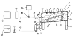
- dry fog is sprayed from the nozzle 5 attached to the side wall 1 b of the cultivation box 1 toward the opposite side wall 1 c, thereby arranging between the left and right side walls 1 b and 1 c of the cultivation box 1. Dry fog is sprayed directly on the root part Pr of the cultivated plant P, the root part Pr is shaken, and a nutrient solution droplet is brought into contact with the root part Pr to absorb the nutrient solution.
- the inclination which inclines upwards toward the side wall 1c side from the lower part of the nozzle 5 by the side wall 1b side by the side of the installation of the nozzle 5 A plate 8 is arranged.
- the length of the inclined plate 8 is slightly shorter than the length L of the cultivation box 1, and a gap for generating a circulating flow is formed between both ends of the inclined plate 8 in the length direction and the inner surfaces of the side walls 1b and 1c of the cultivation box 1.
- 9A and 9B are provided.
- the fog M of dry fog sprayed from the nozzle 5 flows along the upper surface of the inclined plate 8 and then flows to the lower surface side of the inclined plate 8 through the clearance 9 ⁇ / b> A for generating the circulating flow. It flows from the gap 9B to the upper surface side of the inclined plate 8 so that it can circulate with the inclined plate 8 interposed therebetween.
- a fan 11 is installed on the side wall 1c side and below the inclined plate 8, and the mist M flowing above the inclined plate 8 is returned to the lower side, and the mist M surrounds the inclined plate 8 in the cultivation box. I try to circulate. And the required flow rate, the flow rate of 0.7 m / s or more is given to the fog M circulating in the cultivation box 1 in this embodiment.
- the start and stop of spraying from the nozzle 5 are automatically performed by a control device arranged outside the cultivation box 1, and the supply and stop of air to the pressurized air supply pipe 7b are electromagnetic as shown in FIG.
- the on-off valve 43 is opened and closed. Specifically, a pipe 45 connected to the compressor 42 with an air tank 46 interposed therebetween and the pressure air supply pipe 7b are connected via an electromagnetic on-off valve 43, and the electromagnetic on-off valve 43 is connected with a signal from the control device 81. It opens and closes intermittently.
- a pipe 49 connected to the liquid fertilizer tank 47 through a pump 48 is connected to a float valve 31 disposed in the supply liquid tank 30. The float valve 31 in the supply liquid tank 30 floats on the nutrient solution stored in the supply liquid tank 30, and when it becomes less than the set amount, the pump 48 is driven to supply the nutrient solution to the supply liquid tank 30 from the pipe 49. ing.
- the nutrient solution condensed in the cultivation box 1 is discharged from the drain port 34 provided in the cultivation box 1, and the discharged nutrient solution is received and collected by the supply solution tank 30.
- a suction tube serving as the nutrient solution supply pipe 7 a is suspended in the supply solution tank 30, and a strainer 32 is attached to the lower end thereof, and the nutrient solution is sucked up by the air flowing through the nozzle 5 through the strainer 32.
- the electromagnetic on / off valve 43 is turned on / off, or the compressor 42 is turned on / off, spraying from the nozzle 5 is started and stopped after the required time, and the humidity in the cultivation box 1 is set to 95. % To 100% or less.
- the amount of spray from the nozzle 5 is determined in advance by measuring the correlation between the volume of the cultivation box, the amount of spray, the spraying speed and the humidity in the cultivation box, and the humidity in the cultivation box 1 is determined based on the measured data.
- the amount of spray per day from the nozzle 5 necessary to be 95% or more and 100% or less is obtained.
- an opening / closing signal is sent from the control device 81 to the electromagnetic opening / closing valve 43 to perform intermittent spraying or continuous spraying.
- a test cultivation box having a length L of 9 m, a width W of 1 m, a height H of 0.4 m and a volume of 3.6 m 3 was used as the cultivation box 1.
- a nozzle 5 was installed on the inner surface of one end in the length direction in the cultivation box 1, and a fan 11 was installed on the other end side.
- the nozzle 5 has an ability to spray a mist having an average particle diameter of 5 to 10 ⁇ m at 2.4 liters / hour.
- the measurement conditions were changed to the conditions 1 to 3 shown in Tables (A) to (C) of FIG. Each condition 1 to 3 changed the number of fans installed. Spraying was continued from the nozzle 5 at a spraying rate of 2.4 liters / hour.
- the humidity change in the cultivation box 1 by the measurement experiment is shown in FIG. Since the spray is continuously sprayed and the spray amount is 2.4 liters / hour, the humidity at the 5.4 m position from the nozzle position can be 99% and 98%, and the humidity at the 9 m position can be over 97%. did it. And it was found that the humidity inside the box can be increased by increasing the number of fans installed. Therefore, if the length of the cultivation box 1 is 9 m, the volume of the volume is 3.6 m 3 , and the spray amount from one nozzle is 2.4 liters / hour, the humidity in the cultivation box 1 is ensured. It was confirmed that it could be 97% or more.
- the upper surface opening of the cultivation box 1 is closed with the support material 2, the hollow portion 3 is substantially sealed, and the length direction L and the support material 2 disposed above the hollow portion 3 are arranged.
- a sponge in which the cultivated plant P is planted is fitted into a planting hole 22 provided at a predetermined interval in the width direction W, and the root portion Pr of the cultivated plant P is suspended from above in the hollow portion 3.
- the inside of the hollow portion 3 is maintained at a humidity of 95% or more and 100% or less by supplying the nutrient solution from the nozzle 5 at a rate of 2 to 3 liters / hour into the hollow portion 3 having a volume of 2.4 m 3 .
- the mist M is ejected at a speed of 0.7 m / s or more by the spray pressure of the mist M ejected from the nozzle 5 and the wind supplied from the fan 11, and is disposed on the installation side of the nozzle 5 along the upper surface side of the inclined plate 8. It flows from the side wall 1b to the opposite side wall 1c side, and then sucked by the fan 11 and flows from the side wall 1c side to the side wall 1b side on the lower surface side of the inclined plate 8. In this way, the mist M is brought into contact with the root portion Pr while shaking the root portion Pr of the cultivated plant P as a circulation flow without retaining the mist M in the hollow portion 3, and the nutrient solution is absorbed by the root portion Pr.
- dry fog which is an ultra fine mist with an average particle diameter of 5 to 10 ⁇ m sprayed from the nozzle 5
- the humidity in the large cultivation box 1 is 95% or more. It is possible to maintain a near saturation state of 100% or less.
- the mist of the refined nutrient solution By making the mist of the refined nutrient solution in this way, the cultivated plant can easily adsorb the nutrient solution, and at the same time, the oxygen and nitrogen in the air can be easily touched. And since a near saturated state can be maintained, the cultivated plant always adsorbs the nutrient solution, thereby promoting the growth of the cultivated plant and enabling economical farming.
- the nutrient solution can be absorbed into the plant without waste, so the supply of fertilizer and water can be reduced, and cultivation of plants that avoid dense planting and continuous cropping The cost can be reduced.
- the nutrient solution and water storage equipment and piping equipment can be simplified, and the equipment cost can be reduced.
- the two-fluid nozzle 5 does not have an orifice until the gas supply path 54 reaches the gas injection hole 54b from the inlet, so that clogging can be prevented, turbulence does not occur, and Further, since there is no corner portion facing the gas supply path 54, it is possible to prevent the foreign matter contained in the pressure air A from adhering to the inner peripheral surface or corner portion of the gas supply path 54. Therefore, the occurrence of clogging in the gas supply path 54 can be reduced or prevented.
- the liquid supply path 55 side is not provided with an orifice until it reaches the gas-liquid mixing unit 58 from the inlet 55 c, and thus the liquid Q does not generate turbulent flow until it reaches the gas-liquid mixing unit 58. Therefore, it is possible to reduce or prevent the occurrence of clogging due to the foreign matter contained in the liquid Q adhering to the inner peripheral surface surrounding the liquid supply path 55.
- the hydraulic pressure can be gradually increased. That is, although the orifice provided transversely to the flow path is not provided, it has a function of increasing the pressure similarly to the orifice.
- the suction force of the air A sprayed to the center of the gas-liquid mixing unit 58 acts on the liquid Q, and the liquid Q is caused to flow into the gas-liquid mixing unit 8 at high speed to be collided with the air A. Atomization can be achieved.
- a collision pin 51 is provided so as to collide with the gas-liquid mixed fluid to be ejected to generate ultrasonic vibration, and the liquid droplet is refined by this ultrasonic vibration.
- the droplets are prevented from adhering to the collision pin 51 itself, it is possible to prevent the occurrence of the problem that the droplets adhering to the collision pin 51 are blown off as they are and the coarse particles are sprayed.
- the droplets ejected by ultrasonic vibration are miniaturized, coarse particles are not sprayed, and deterioration of efficiency due to the spraying of coarse particles can be prevented.
- This invention is not limited to the said embodiment,
- the installation number of the nozzle 5 and the installation number of the fan 11 are increased so that the humidity in the cultivation box 1 can be maintained at 95% or more. I have to.
- the nozzles 5 that spray toward the downstream side are disposed on both side walls or the upper surface of the intermediate position in the length direction. In any case, one nozzle 5 per volume of 6 m 3 is installed in the hollow portion in the cultivation box 1.
- the shape of the upper surface of the cultivation box for planting the cultivated plant may be a triangle shape and a shape provided with stairs on both sides.
- the two-fluid nozzle used in the present invention is not limited to the nozzles shown in FIGS. 5 and 6, and instead of providing an orifice that is likely to be clogged in the flow path in the nozzle body, the flow path is directed to the injection side. It is suitably used as long as it is gradually reduced to increase the fluid pressure, and the spray sprayed from the nozzle is made to collide with the collision pin and be miniaturized.
Abstract
Cette invention concerne un dispositif pour la culture des plantes qui permet de réduire la quantité de nutriments liquides et d'eau utilisée. Dans une boîte de culture creuse dans laquelle les racines des plantes cultivées pendent verticalement, des buses sont ménagées, lesdites buses pulvérisant les nutriments liquides sous la forme d'un brouillard ayant un diamètre de particules moyen, mesuré par un procédé de mesure laser, de 5 à 10 µm, à une quantité de pulvérisation de 2 à 3 litres à l'heure. Le nombre et la position des buses sont déterminés en fonction de la forme de la boîte de culture de façon qu'il y ait une buse pour un maximum de 6 m3 par rapport au volume intérieur de la boîte de culture. De plus, un dispositif de commande de buses peut être utilisé pour que la pulvérisation provenant des buses maintienne l'humidité intérieure de la boîte de culture dans une plage de 95 à 100 %.
Priority Applications (2)
| Application Number | Priority Date | Filing Date | Title |
|---|---|---|---|
| PCT/JP2012/056498 WO2013136459A1 (fr) | 2012-03-14 | 2012-03-14 | Dispositif pour la culture des plantes |
| JP2014504549A JP5792888B2 (ja) | 2012-03-14 | 2012-03-14 | 植物栽培装置 |
Applications Claiming Priority (1)
| Application Number | Priority Date | Filing Date | Title |
|---|---|---|---|
| PCT/JP2012/056498 WO2013136459A1 (fr) | 2012-03-14 | 2012-03-14 | Dispositif pour la culture des plantes |
Publications (1)
| Publication Number | Publication Date |
|---|---|
| WO2013136459A1 true WO2013136459A1 (fr) | 2013-09-19 |
Family
ID=49160428
Family Applications (1)
| Application Number | Title | Priority Date | Filing Date |
|---|---|---|---|
| PCT/JP2012/056498 WO2013136459A1 (fr) | 2012-03-14 | 2012-03-14 | Dispositif pour la culture des plantes |
Country Status (2)
| Country | Link |
|---|---|
| JP (1) | JP5792888B2 (fr) |
| WO (1) | WO2013136459A1 (fr) |
Cited By (9)
| Publication number | Priority date | Publication date | Assignee | Title |
|---|---|---|---|---|
| CN104054566A (zh) * | 2014-06-13 | 2014-09-24 | 张家港永联天天鲜配送有限公司 | 无土栽培分段栽培池 |
| FR3031003A1 (fr) * | 2014-12-31 | 2016-07-01 | Gerard Varesano | Module de culture hors-sol dans lequel les racines des vegetaux sont alimentees par un brouillard nutritif, ensemble de modules et procede associe. |
| WO2018123922A1 (fr) * | 2016-12-28 | 2018-07-05 | 株式会社いけうち | Buse |
| CN109042274A (zh) * | 2018-07-24 | 2018-12-21 | 江苏大学 | 一种包裹根系精准喷雾的超声雾化栽培箱及其方法 |
| CN109275559A (zh) * | 2018-12-07 | 2019-01-29 | 四维生态科技(杭州)有限公司 | 一种无土栽培装置及方法 |
| WO2019065405A1 (fr) * | 2017-09-26 | 2019-04-04 | 国立研究開発法人産業技術総合研究所 | Buse et pulvérisateur |
| WO2019069826A1 (fr) * | 2017-10-02 | 2019-04-11 | 株式会社いけうち | Appareil de culture de plantes |
| WO2020005166A1 (fr) | 2018-06-25 | 2020-01-02 | Muanchart Mankaew | Procédé de culture de plantes avec un petit élément |
| WO2023008688A1 (fr) * | 2021-07-29 | 2023-02-02 | 록야 주식회사 | Lit mélangé pour culture de plantes, sur lequel une technique à écoulement profond et une culture aéroponique peuvent être utilisées de façon sélective |
Families Citing this family (2)
| Publication number | Priority date | Publication date | Assignee | Title |
|---|---|---|---|---|
| KR101892977B1 (ko) * | 2018-06-20 | 2018-08-30 | 권우진 | 수증기를 이용한 화분 |
| KR102383609B1 (ko) * | 2019-11-27 | 2022-04-06 | 주식회사 미드바르 | 공기에서 추출된 물을 이용한 식물 재배 시스템 |
Citations (3)
| Publication number | Priority date | Publication date | Assignee | Title |
|---|---|---|---|---|
| JPH0994487A (ja) * | 1995-10-03 | 1997-04-08 | Kyoritsu Gokin Seisakusho:Kk | 霧化ノズル |
| JP2003320278A (ja) * | 2002-04-26 | 2003-11-11 | Fuji Electric Co Ltd | オゾン水噴霧ノズル装置 |
| JP2012010651A (ja) * | 2010-06-30 | 2012-01-19 | Ikeuchi:Kk | 植物栽培装置、育苗装置および植物栽培方法 |
-
2012
- 2012-03-14 WO PCT/JP2012/056498 patent/WO2013136459A1/fr active Application Filing
- 2012-03-14 JP JP2014504549A patent/JP5792888B2/ja active Active
Patent Citations (3)
| Publication number | Priority date | Publication date | Assignee | Title |
|---|---|---|---|---|
| JPH0994487A (ja) * | 1995-10-03 | 1997-04-08 | Kyoritsu Gokin Seisakusho:Kk | 霧化ノズル |
| JP2003320278A (ja) * | 2002-04-26 | 2003-11-11 | Fuji Electric Co Ltd | オゾン水噴霧ノズル装置 |
| JP2012010651A (ja) * | 2010-06-30 | 2012-01-19 | Ikeuchi:Kk | 植物栽培装置、育苗装置および植物栽培方法 |
Cited By (20)
| Publication number | Priority date | Publication date | Assignee | Title |
|---|---|---|---|---|
| CN104054566A (zh) * | 2014-06-13 | 2014-09-24 | 张家港永联天天鲜配送有限公司 | 无土栽培分段栽培池 |
| CN104054566B (zh) * | 2014-06-13 | 2016-08-31 | 张家港市永联菜篮农业专业合作社 | 无土栽培分段栽培池 |
| FR3031003A1 (fr) * | 2014-12-31 | 2016-07-01 | Gerard Varesano | Module de culture hors-sol dans lequel les racines des vegetaux sont alimentees par un brouillard nutritif, ensemble de modules et procede associe. |
| WO2016108031A1 (fr) * | 2014-12-31 | 2016-07-07 | Varesano Gérard | Module de culture hors-sol dans lequel les racines des végétaux sont alimentées par un brouillard nutritif, ensemble de modules et procédé associé |
| US10681876B2 (en) | 2014-12-31 | 2020-06-16 | Gérard Varesano | Above-ground farming module in which the roots of the plants are fed by a nutritional mist, set of modules and associated method |
| CN109952156A (zh) * | 2016-12-28 | 2019-06-28 | 株式会社池内 | 喷嘴 |
| CN109952156B (zh) * | 2016-12-28 | 2021-06-04 | 株式会社池内 | 喷嘴 |
| WO2018123922A1 (fr) * | 2016-12-28 | 2018-07-05 | 株式会社いけうち | Buse |
| JP2018108554A (ja) * | 2016-12-28 | 2018-07-12 | 株式会社いけうち | ノズル |
| JPWO2019065405A1 (ja) * | 2017-09-26 | 2020-04-23 | 国立研究開発法人産業技術総合研究所 | ノズルおよびスプレー |
| WO2019065405A1 (fr) * | 2017-09-26 | 2019-04-04 | 国立研究開発法人産業技術総合研究所 | Buse et pulvérisateur |
| WO2019069826A1 (fr) * | 2017-10-02 | 2019-04-11 | 株式会社いけうち | Appareil de culture de plantes |
| CN111182787A (zh) * | 2017-10-02 | 2020-05-19 | 株式会社池内 | 植物栽培装置 |
| JPWO2019069826A1 (ja) * | 2017-10-02 | 2020-10-22 | 株式会社いけうち | 植物栽培装置 |
| JP7216423B2 (ja) | 2017-10-02 | 2023-02-01 | 株式会社いけうち | 植物栽培装置 |
| WO2020005166A1 (fr) | 2018-06-25 | 2020-01-02 | Muanchart Mankaew | Procédé de culture de plantes avec un petit élément |
| CN109042274A (zh) * | 2018-07-24 | 2018-12-21 | 江苏大学 | 一种包裹根系精准喷雾的超声雾化栽培箱及其方法 |
| CN109042274B (zh) * | 2018-07-24 | 2020-11-20 | 江苏大学 | 一种包裹根系精准喷雾的超声雾化栽培箱及其方法 |
| CN109275559A (zh) * | 2018-12-07 | 2019-01-29 | 四维生态科技(杭州)有限公司 | 一种无土栽培装置及方法 |
| WO2023008688A1 (fr) * | 2021-07-29 | 2023-02-02 | 록야 주식회사 | Lit mélangé pour culture de plantes, sur lequel une technique à écoulement profond et une culture aéroponique peuvent être utilisées de façon sélective |
Also Published As
| Publication number | Publication date |
|---|---|
| JPWO2013136459A1 (ja) | 2015-08-03 |
| JP5792888B2 (ja) | 2015-10-14 |
Similar Documents
| Publication | Publication Date | Title |
|---|---|---|
| JP5792888B2 (ja) | 植物栽培装置 | |
| JP2012223127A (ja) | 植物栽培装置 | |
| JP6613525B2 (ja) | 植物栽培装置 | |
| JP7216423B2 (ja) | 植物栽培装置 | |
| US20090293357A1 (en) | Aeroponic atomizer for horticulture | |
| CN201640135U (zh) | 芽菜培育装置 | |
| EP3694306B1 (fr) | Dispositif aéroponique | |
| US10492387B1 (en) | Aeroponic recycling system | |
| JP2012010651A (ja) | 植物栽培装置、育苗装置および植物栽培方法 | |
| JP2015012841A (ja) | 植物栽培装置 | |
| KR20170091186A (ko) | 수경 재배 장치 및 수경 재배 방법 | |
| CN105993898A (zh) | 一种气雾栽培系统 | |
| JP2010523129A (ja) | 水栽培システム | |
| KR101818219B1 (ko) | 분무 수경 재배 장치 | |
| JP2012196164A (ja) | 植物栽培装置 | |
| CN107683760A (zh) | 水培和气雾培结合的薯类种植装置 | |
| KR102450980B1 (ko) | 식물재배기 | |
| JP6857853B2 (ja) | ミスト発生システム、農業用ハウス | |
| JP7067701B2 (ja) | 超音波霧化栽培装置 | |
| CN205320684U (zh) | 一种喷雾式植物栽培装置 | |
| JP2000188980A (ja) | 栽培方法および装置 | |
| KR102249679B1 (ko) | 식물 재배 장치 | |
| CN107787661B (zh) | 小麦水肥一体喷灌系统 | |
| KR200398840Y1 (ko) | 물안개를 이용한 수경재배기 | |
| RU2341956C2 (ru) | Способ распыления жидкости на виноградниках и устройство для его осуществления |
Legal Events
| Date | Code | Title | Description |
|---|---|---|---|
| 121 | Ep: the epo has been informed by wipo that ep was designated in this application |
Ref document number: 12871571 Country of ref document: EP Kind code of ref document: A1 |
|
| ENP | Entry into the national phase |
Ref document number: 2014504549 Country of ref document: JP Kind code of ref document: A |
|
| NENP | Non-entry into the national phase |
Ref country code: DE |
|
| 122 | Ep: pct application non-entry in european phase |
Ref document number: 12871571 Country of ref document: EP Kind code of ref document: A1 |