WO2013133151A1 - 電気自動車のハーネス配策構造 - Google Patents
電気自動車のハーネス配策構造 Download PDFInfo
- Publication number
- WO2013133151A1 WO2013133151A1 PCT/JP2013/055635 JP2013055635W WO2013133151A1 WO 2013133151 A1 WO2013133151 A1 WO 2013133151A1 JP 2013055635 W JP2013055635 W JP 2013055635W WO 2013133151 A1 WO2013133151 A1 WO 2013133151A1
- Authority
- WO
- WIPO (PCT)
- Prior art keywords
- harness
- charging
- clip
- quick charge
- power unit
- Prior art date
- Legal status (The legal status is an assumption and is not a legal conclusion. Google has not performed a legal analysis and makes no representation as to the accuracy of the status listed.)
- Ceased
Links
Images





Classifications
-
- B—PERFORMING OPERATIONS; TRANSPORTING
- B60—VEHICLES IN GENERAL
- B60R—VEHICLES, VEHICLE FITTINGS, OR VEHICLE PARTS, NOT OTHERWISE PROVIDED FOR
- B60R16/00—Electric or fluid circuits specially adapted for vehicles and not otherwise provided for; Arrangement of elements of electric or fluid circuits specially adapted for vehicles and not otherwise provided for
- B60R16/02—Electric or fluid circuits specially adapted for vehicles and not otherwise provided for; Arrangement of elements of electric or fluid circuits specially adapted for vehicles and not otherwise provided for electric constitutive elements
- B60R16/0207—Wire harnesses
- B60R16/0215—Protecting, fastening and routing means therefor
-
- B—PERFORMING OPERATIONS; TRANSPORTING
- B60—VEHICLES IN GENERAL
- B60K—ARRANGEMENT OR MOUNTING OF PROPULSION UNITS OR OF TRANSMISSIONS IN VEHICLES; ARRANGEMENT OR MOUNTING OF PLURAL DIVERSE PRIME-MOVERS IN VEHICLES; AUXILIARY DRIVES FOR VEHICLES; INSTRUMENTATION OR DASHBOARDS FOR VEHICLES; ARRANGEMENTS IN CONNECTION WITH COOLING, AIR INTAKE, GAS EXHAUST OR FUEL SUPPLY OF PROPULSION UNITS IN VEHICLES
- B60K1/00—Arrangement or mounting of electrical propulsion units
- B60K1/04—Arrangement or mounting of electrical propulsion units of the electric storage means for propulsion
- B60K2001/0405—Arrangement or mounting of electrical propulsion units of the electric storage means for propulsion characterised by their position
- B60K2001/0438—Arrangement under the floor
Definitions
- the present invention relates to a harness arrangement structure for an electric vehicle in which a power unit and a charging port are connected by a charging harness.
- the converter, the charger, and the charging port are both fixed to the vehicle body, and the charging port does not move relative to the converter and the charger. For this reason, the quick charging harness and the normal charging harness that connect them are not deformed by vibration, and each charging harness is freely arranged according to the vehicle layout.
- the converter, the charger, and the charging port move relatively when vibration occurs. Therefore, it is necessary to deform each charging harness in accordance with the relative movement to prevent the occurrence of harness damage.
- each charging harness has a predetermined rigidity and thickness. have. Therefore, unless the distance between the restraint points that restrain each charging harness (straight line length when the restraint points are connected by a straight line) is not secured to some extent, it is necessary for each charging harness to absorb relative movement. A margin (deflection) could not be provided. On the other hand, if the restraint points are separated from each other in the vehicle front-rear direction in order to ensure the distance between the restraint points, a problem arises that the vehicle body dimension in the vehicle front-rear direction increases.
- the present invention has been made paying attention to the above problem, and provides a harness arrangement structure for an electric vehicle that can suppress an increase in the vehicle body dimension in the vehicle front-rear direction when the power unit and the charging port that move relative to each other are connected by a charging harness. For the purpose.
- the harness arrangement structure for an electric vehicle includes a power unit, a charging port, a charging harness, a first harness clip, and a second harness clip.
- the power unit includes an electric motor as a travel drive source, and a control device that controls the electric motor and controls charging of a battery that supplies electric power to the electric motor, and is elastically supported by the vehicle body.
- the charging port is fixedly supported on the vehicle body.
- the charging harness connects the power unit and the charging port.
- the first harness clip fixes the middle of the charging harness to the vehicle body.
- the second harness clip fixes the middle of the charging harness between the first harness clip and the power unit to the power unit, and is provided at a height different from the height of the first harness clip.
- the middle of the charging harness connecting the power unit and the charging port is fixed to the vehicle body by the first harness clip. Further, the middle of the charging harness between the first harness clip and the power unit is fixed to the power unit elastically supported by the vehicle body by the second harness clip. And the height of a 1st harness clip and the height of a 2nd harness clip are varied. That is, by providing a height difference between the first harness clip and the second harness clip, the distance between the first harness clip and the second harness clip in the vehicle front-rear direction is longer than the first harness clip to the second harness clip. The linear distance dimension is longer.
- the distance between the restraint point by the first harness clip and the restraint point by the second harness clip (the restraint points are connected by a straight line).
- the length of the charging harness is long enough to bend.
- the increase of the vehicle body dimension of a vehicle front-back direction can be suppressed by ensuring the distance between restraint points by the height difference between the 1st, 2nd harness clips.
- FIG. 1 It is a whole side view which shows the main structures of the electric vehicle to which the harness routing structure of Example 1 was applied. It is a schematic plan view which shows the front main structure of the electric vehicle to which the harness arrangement structure of Example 1 was applied. It is a schematic side view which shows the front part main structure of the electric vehicle to which the harness routing structure of Example 1 was applied. It is a perspective view which shows the quick charge harness of Example 1, and a normal charge harness. It is a perspective view which shows the 1st quick charge harness clip which fixes the quick charge harness of Example 1. FIG. It is a perspective view which shows the 2nd quick charge harness clip which fixes the quick charge harness of Example 1. FIG. It is a side view which shows the quick charge harness of Example 1. FIG.
- FIG. 1 It is a top view which shows the quick charge harness of Example 1.
- FIG. 1 It is a perspective view when the quick charge harness of Example 1 is seen from the vehicle rear. It is a rear view when the quick charge harness of Example 1 is seen from the vehicle rear. It is a side view which shows the quick charge harness of Example 1, and a normal charge harness. It is a top view which shows the quick charge harness of Example 1, and a normal charge harness.
- the configuration of the harness arrangement structure of the electric vehicle according to the first embodiment will be described by dividing it into “basic configuration of electric vehicle”, “arrangement configuration of rapid charging harness”, and “arrangement configuration of ordinary charging harness”.
- FIG. 1 is an overall side view showing a main structure of an electric vehicle to which the harness routing structure of the first embodiment is applied.
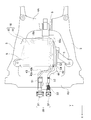
- FIG. 2 is a schematic plan view showing the main structure of the front portion of the electric vehicle to which the harness routing structure of the first embodiment is applied.
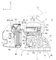
- FIG. 3 is a schematic side view showing the main structure of the front portion of the electric vehicle to which the harness routing structure of the first embodiment is applied.
- the direction indicated by arrow X is the vehicle front-rear direction
- the direction indicated by arrow Y is the vehicle width direction
- the direction indicated by arrow Z is the vehicle vertical direction.
- the electric vehicle 1 of Example 1 is provided with the power unit 10, the battery unit (battery) 20, and the charge port 30, as shown in FIG.
- the power unit 10 includes a motor drive unit 11 and a high-power unit (control device) 15 that is integrally mounted on the motor drive unit 11 and is disposed in a motor room 2 formed at the front of the vehicle body. ing.
- the power unit 10 includes a pair of front side members (vehicle bodies) 3 and 3 extending in the vehicle front-rear direction and a first front cross member (a first front cross member for connecting the pair of front side members 3 and 3 behind the power unit 10). It is elastically supported by the vehicle body 4A through the mount member 5. That is, the power unit 10 is elastically supported by the vehicle body (here, the pair of front side members 3 and 3 and the first front cross member 4A) via the mount member 5.
- the mount member 5 is attached to a motor drive unit 11 disposed on the lower side of the power unit 10.
- the motor drive unit 11 includes an electric motor 12 as a travel drive source of the electric vehicle 1, a speed reducer 13 that decelerates the rotation of the electric motor 12 and transmits it to the differential gear 13 a, and the electric motor 12 and the speed reducer 13. And a built-in motor housing 14.
- the electric motor 12 is used not only as a travel drive source (power running) but also as a generator (regeneration).
- the high-power unit 15 controls the motor driving unit 11 and controls the charging of the battery unit 20, and includes an inverter 16 and a high-power module 17.
- the inverter 16 is connected to the motor drive unit 11 via a three-phase AC harness (not shown), and converts between a direct current and a three-phase alternating current.
- the inverter 16 converts the direct current from the high-power module 17 into a three-phase alternating current when the electric motor 12 is powered and supplies it to the electric motor 12.
- the inverter 16 A three-phase alternating current is converted into a direct current and supplied to the high voltage module 17.
- the inverter 16 is built in the inverter housing 16 a and is mounted immediately above the motor drive unit 11.
- the high-power module 17 is a voltage control device that controls the voltage of the power supplied to the motor drive unit 11 and the power charged in the battery unit 20, and includes a DC / DC converter and a charger.
- the high-power module 17 is built in the high-power module housing 17 a and is mounted immediately above the inverter 16.
- the high-power module 17 is connected to the battery unit 20 via the charge / discharge harness 41, connected to the charge port 30 via the charge harness 42, and connected to the inverter 16 via a high-voltage harness (not shown).
- the DC / DC converter converts a quick charge voltage from an external quick charge power source (not shown) into a charge voltage and charges the battery unit 20.
- the DC / DC converter converts the charging voltage from the battery unit 20 into a driving voltage and supplies it to the inverter 16 when the electric motor 12 is powered, and charges the generated voltage from the inverter 16 when the electric motor 12 is regenerated.
- the battery unit 20 is charged by converting into voltage.
- the charger converts a normal charging voltage from an external normal charging power source (not shown) into a charging voltage and charges the battery unit 20.
- the battery unit 20 stores electric power supplied via the charging port 30 and electric power regenerated by the electric motor 12 and supplies electric power stored for driving the electric motor 12.
- the battery unit 20 includes a large number of battery modules including secondary batteries, a control circuit that controls charging / discharging of the battery modules, a cooling device, and the like, and a battery housing 21 in which these are built.
- a charge / discharge terminal 21 a for connecting the charge / discharge harness 41 is formed at the center of the front end of the battery housing 21.
- As the secondary battery a lithium ion battery, a chargeable / dischargeable nickel cadmium battery, a nickel metal hydride battery, or the like is used.
- the battery unit 20 is disposed below the vehicle body floor 6 located behind the motor room 2.
- a dash panel 7 stands between the motor room 2 and the vehicle body floor 6, and the vehicle body floor 6 constitutes a floor surface of the vehicle compartment 8 partitioned from the motor room 2 by the dash panel 7.
- the charging port 30 is a power receiving unit that inputs external power for charging the battery unit 20 by contact-connecting an external power source (not shown), and includes a quick charging port 31 and a normal charging port 32. Further, the charging port 30 is held via the charging port bracket 33 at a substantially central position in the vehicle width direction of the front portion of the motor room 2 and above the front bumper 9. That is, the charging port 30 is disposed in front of the power unit 10.
- the charging port bracket 33 includes a leg portion 33a, a port housing 33b, and a clip fixing portion 33c. The lower end of the leg 33a is fixed to a second front cross member (vehicle body) 4B that connects the pair of front side members 3 and 3 in front of the power unit 10, and extends upward.
- the port housing 33b is fixed to the upper portion of the leg portion 33a and holds the charging port 30.
- the clip fixing portion 33c fixes and supports the charging harness 42 connected to the charging port 30 in the vicinity of the port housing 33b. That is, the charging port 30 is fixedly supported on the vehicle body (here, the second front cross member 4B) via the charging port bracket 33.
- the rapid charging port 31 is connected to a rapid charger that is a high-voltage DC power supply, and is connected to the high-power module 17 via a rapid charging harness 43 that is a charging harness 42 through which a high-voltage current flows.
- the normal charging port 32 is connected to a low-voltage AC power source of about 100 to 200 volts for home use, and is a normal charging harness that is a charging harness 42 in which a current having a voltage lower than that flowing through the quick charging harness 43 flows.
- the high voltage module 17 is connected to the high voltage module 17 through 44.
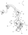
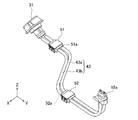
- FIG. 4 is a perspective view illustrating the quick charging harness and the normal charging harness according to the first embodiment.
- FIG. 5 is a perspective view showing a first quick charge harness clip for fixing the quick charge harness of the first embodiment.
- FIG. 6 is a perspective view showing a second quick charge harness clip for fixing the quick charge harness of the first embodiment.
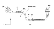
- FIG. 7A is a side view showing the quick charging harness of the first embodiment.
- FIG. 7B is a plan view illustrating the rapid charging harness according to the first embodiment.
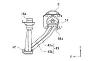
- FIG. 7C is a perspective view of the quick charging harness according to the first embodiment when viewed from the rear of the vehicle.
- FIG. 7D is a rear view of the quick charging harness according to the first embodiment when viewed from the rear of the vehicle.
- the direction indicated by arrow X is the vehicle front-rear direction
- the direction indicated by arrow Y is the vehicle width direction
- the direction indicated by arrow Z is the vehicle vertical direction.
- the rapid charging harness 43 is composed of a pair of harnesses (first harness 43 a and second harness 43 b), one end of which is connected to the rapid charging port 31, and the high voltage connector 18 a provided at the other end of the high voltage module 17. It is connected to the quick charging harness connection terminal 17b.
- the harness diameter is larger than that of the normal charging harness 44 and has rigidity that hardly deforms by its own weight.
- the minimum radius of curvature when bending the first and second harnesses 43a and 43b is about R120 to R130.
- the quick charge harness 43 is fixed to the clip fixing portion 33c of the charge port bracket 33 through the first quick charge harness clip (first harness clip) 51 at a midway position in the vicinity of the quick charge port 31.
- the intermediate position of the quick charging harness 43 between the first quick charging harness clip 51 and the high power module 17 is fixed to the high power module 17 of the power unit 10 via the second quick charging harness clip (second harness clip) 52. Is done.
- the second quick charge harness clip 52 is attached to a clip bracket 16c provided on a side surface 16b facing the vehicle side of the inverter housing 16a.
- the first quick charge harness clip 51 restrains a part of the quick charge harness 43 with a predetermined restraining width in the length direction, as shown in FIG. A portion of the quick charge harness 43 that is restrained by the first quick charge harness clip 51 is in a horizontal direction with respect to the vehicle vertical direction in a state in which the harness interval between the first harness 43a and the second harness 43b is maintained. Be bound.
- the second quick charge harness clip 52 restrains a part of the quick charge harness 43 with a predetermined restraining width in the length direction.
- the portion of the quick charge harness 43 that is restrained by the second quick charge harness clip 52 is in a horizontal direction with respect to the vehicle vertical direction while maintaining the harness interval between the first harness 43a and the second harness 43b. Be bound.
- the second quick charge harness clip 52 is provided at a position lower than the height position of the first quick charge harness clip 51.
- the first quick charge harness clip 51 is provided at substantially the same height as the quick charge port 31.
- the second quick charge harness clip 52 is provided at substantially the same height as the boundary between the motor drive unit 11 and the high power unit 15 of the power unit 10, which is lower than the quick charge port 31.
- the height of the first quick charge harness clip 51 and the height of the second quick charge harness clip 52 are different, and when the height position of the first quick charge harness clip 51 is used as a reference, the second quick charge harness clip 51
- the clip 52 is offset from the height position of the first quick charge harness clip 51 toward the mount member 5 that elastically supports the lower portion of the power unit 10 (see FIG. 3).
- the first quick charge harness clip 51 is disposed at a substantially central position in the vehicle width direction immediately after the quick charge port 31.
- the second quick charge harness clip 52 is provided on the side surface of the power unit 10 (here, the side surface 16b facing the vehicle side of the inverter housing 16a), and the vehicle width is wider than the first quick charge harness clip 51. Offset outward in the direction. That is, the position of the first quick charge harness clip 51 in the vehicle width direction and the position of the second quick charge harness clip 52 in the vehicle width direction are different.
- the harnesses 43a and 43b between the two R portions are inclined in the vehicle width direction, and the R portion is also bent in the vehicle width direction (see FIG. 7B).
- the surplus length of the quick charging harness 43 at this time is set to be longer than at least the dimension allowing the mount member 5 to vibrate.
- the lengths of the first harness 43a and the second harness 43b are aligned between the rapid vehicle body restraint point 51a and the rapid unit restraint point 52a. That is, the length of the first harness 43a from the rapid vehicle body side restraint point 51a to the rapid unit side restraint point 52a is equal to the length of the second harness 43b from the rapid vehicle body side restraint point 51a to the rapid unit side restraint point 52a. Further, in the quick charging harness 43, the first harness 43a and the second harness 43b are arranged in parallel between the rapid vehicle body restraint point 51a and the rapid unit restraint point 52a, and the mutual harness interval is made constant. ing.
- the “rapid vehicle body side restraint point” is an end portion on the power unit 10 side of a part of the rapid charge harness 43 restrained by the first quick charge harness clip 51. Further, the “rapid unit side restraint point” is an end portion on the charge port 30 side of a part of the quick charge harness 43 restrained by the second quick charge harness clip 52.
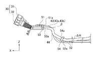
- FIG. 8A is a side view illustrating the quick charging harness and the normal charging harness according to the first embodiment.
- FIG. 8B is a plan view illustrating the quick charge harness and the normal charge harness according to the first embodiment.
- the direction indicated by arrow X is the vehicle front-rear direction
- the direction indicated by arrow Y is the vehicle width direction
- the direction indicated by arrow Z is the vehicle vertical direction.
- the normal charging harness 44 is configured by covering a pair of harnesses (not shown) together with a buffer member, one end is connected to the normal charging port 32, and the other end 18 b is a normal charging harness connection terminal of the high voltage module 17. (Not shown).
- the harness diameter is smaller than that of the quick charging harness 43 and has rigidity that can be deformed by its own weight.
- the normal charging harness 44 is routed outside the quick charging harness 43 in the vehicle width direction.
- the middle of the normal charging harness 44 is fixed to the clip fixing portion 33 c of the charging port bracket 33 through the first normal charging harness clip 53. Further, the middle of the normal charging harness 44 between the first normal charging harness clip 53 and the high power module 17 is fixed to the high power module 17 of the power unit 10 via the second normal charging harness clip 54.
- the second normal charging harness clip 54 is attached to the clip bracket 16c.
- the first ordinary charging harness clip 53 restrains a part of the ordinary charging harness 44 with a predetermined restraining width in the length direction on the side of the first quick charging harness clip 51.
- a portion of the normal charging harness 44 that is restrained by the first ordinary charging harness clip 53 is restrained in the horizontal direction with respect to the vehicle vertical direction.
- the normal vehicle-side restraint point 53a by the first normal charging harness clip 53 is a position in the vehicle front-rear direction, as shown by the rapid vehicle-side restraint point 51a by the first quick charge harness clip 51 and the broken line ⁇ in FIG. 8B.
- the positions in the vehicle vertical direction match as shown by the broken line ⁇ in FIG. 8A.
- the “ordinary vehicle side restraint point” is an end portion on the power unit 10 side of a part of the ordinary charging harness 44 restrained by the first ordinary charging harness clip 53.
- the second ordinary charging harness clip 54 restrains a part of the ordinary charging harness 44 with a predetermined restraining width in the length direction on the side of the second quick charging harness clip 52.
- the portion of the normal charging harness 44 that is constrained by the second normal charging harness clip 54 is such that the normal unit side restraint point 54a by the second normal charging harness clip 54 faces the front of the vehicle with respect to the vehicle vertical direction. It is restrained in the state which inclined diagonally. That is, the second ordinary charging harness clip 54 restrains the ordinary charging harness 44 to tilt forward. Further, the normal unit side restraint point 54 a by the second normal charging harness clip 54 is positioned in front of the vehicle and above the vehicle with respect to the quick unit side restraint point 52 a by the second quick charging harness clip 52.
- a distance (gap) indicated by ⁇ W in FIG. 8B is generated in the vehicle front-rear direction between the rapid unit side restraint point 52a and the normal unit side restraint point 54a.
- a distance (gap) indicated by ⁇ H in FIG. 8A is generated in the vehicle vertical direction between the rapid unit side restraint point 52a and the normal unit side restraint point 54a.
- the length of the normal charging harness 44 between the normal vehicle body side restraint point 53a and the normal unit side restraint point 54a is the same as the length of the quick charge harness 43 between the rapid vehicle body side restraint point 51a and the rapid unit side restraint point 52a. Shorter than that.
- the “ordinary unit side restraint point” is an end portion on the charging port 30 side of a part of the ordinary charging harness 44 restrained by the second ordinary charging harness clip 54.
- the quick charger port 31 of the charging port 30 is connected to a quick charger as appropriate. Therefore, the quick charging port 31 needs to be fixed in position with respect to the vehicle body, and is fixedly supported by the vehicle body via the charging port bracket 33.
- the electric motor 12 vibrates due to the rotation of the rotor during driving.
- the electric motor 12 is built in the motor housing 14 of the motor drive unit 11, but the high-power unit 15 is integrally mounted on the upper portion of the motor housing 14. Therefore, when the electric motor 12 vibrates, not only the motor drive unit 11 but also the high-power unit 15 vibrates in the same manner, and the entire power unit 10 vibrates as a whole.
- the power unit 10 is elastically supported by the vehicle body via the mount member 5.
- the power unit 10 vibrates, the vibration is absorbed by the mount member 5 and is not transmitted to the vehicle body, and the quick charge port 31 does not vibrate. That is, when the power unit 10 vibrates, the power unit 10 and the quick charge port 31 move relatively, and the interval between the power unit 10 and the quick charge port 31 increases or decreases.
- the power unit 10 and the quick charge port 31 are connected by a quick charge harness 43.
- the middle portion of the quick charge harness 43 is fixed to the vehicle body by the first quick charge harness clip 51 and fixed to the power unit 10 by the second quick charge harness clip 52. Further, by bending the quick charge harness 43 between the first quick charge harness clip 51 and the second quick charge harness clip 52, it is possible to deform the harness when the power unit 10 and the quick charge port 31 are relatively moved. Relative movement is allowed.
- the rapid vehicle-side restraint point 51a by the first quick-charge harness clip 51 and the rapid unit-side restraint point 52a by the second quick-charge harness clip 52 are brought close to the extent that the quick-charge harness 43 cannot be curved. Then, the quick charging harness 43 cannot be bent. That is, since the quick charging harness 43 has a predetermined thickness and rigidity, a certain distance between the restraint points is required to bend the quick charging harness 43. If the quick charge harness 43 cannot be bent, the quick charge harness 43 cannot be deformed in accordance with the relative movement between the power unit 10 and the quick charge port 31. That is, when the interval between the power unit 10 and the quick charging port 31 is widened by the vibration of the power unit 10, the quick charging harness 43 is pulled. Further, when the distance between the power unit 10 and the quick charging port 31 is narrowed due to the vibration of the power unit 10, the quick charging harness 43 may be compressed in the vibration direction and bend extremely. As a result, there arises a problem that the harness is damaged.
- the distance between the restraint points for restraining the quick charge harness 43 is ensured to allow the harness to be bent.
- the charging harness 43 needs to be bent.
- the distance between the restraint points is secured, if the first quick charge harness clip 51 and the second quick charge harness clip 52 are separated in the vehicle front-rear direction, the vehicle dimensions increase in the vehicle front-rear direction. This causes a problem that the layout is not preferable.
- the quick charging harness 43 between the rapid vehicle body side restraint point 51a and the rapid unit side restraint point 52a is bent. Therefore, even if the distance between restraint points fluctuates because the power unit 10 vibrates, the quick charging harness 43 can be deformed to absorb the vibration.
- the first quick charge harness clip 51 is provided at a position substantially the same as the quick charge port 31, and the second quick charge harness clip 52 is provided at a position lower than the quick charge port 31. That is, the heights of the first quick charge harness clip 51 and the second quick charge harness clip 52 are different.
- the 1st quick charge harness clip 51 and the 2nd quick charge harness clip 52 are different between the restraint points as in the first embodiment. The distance can be increased.
- the rapid vehicle body side restraint point 51a and the rapid unit side restraint point 52a can be separated from each other. A point-to-point distance can be secured. Thereby, the quick charging harness 43 between the rapid vehicle body side restraint point 51a and the rapid unit side restraint point 52a can be sufficiently bent. As a result, the required length of the quick charging harness 43 that connects the power unit 10 and the quick charging port 31 that move relative to each other can be ensured.
- first quick charge harness clip 51 and the second quick charge harness clip 52 and the second quick charge harness clip 52 are separated from each other in the vehicle vertical direction so as to secure the distance between the restraint points. There is no need to separate the clip 52 from the vehicle longitudinal direction. Therefore, an increase in the vehicle body dimension in the vehicle front-rear direction can be suppressed.
- the first quick charge harness clip 51 is disposed at a substantially central position in the vehicle width direction immediately after the quick charge port 31, and the second quick charge harness clip 52 is disposed on the side surface of the power unit 10. Provided. Thereby, the position of the first quick charge harness clip 51 in the vehicle width direction and the position of the second quick charge harness clip 52 in the vehicle width direction are different.
- the 1st quick charge harness clip 51 and the 2nd quick charge harness clip 52 are made different in the vehicle width direction position as in the first embodiment.
- the distance between the restraint points can be increased.
- the distance between the restraint points can be further ensured without increasing the vehicle body dimension in the vehicle longitudinal direction.
- the 2nd quick charge harness clip 52 is made from the height position of the 1st quick charge harness clip 51.
- the lower part of the power unit 10 is offset toward the mount member 5 that elastically supports. That is, the second quick charge harness clip 52 that vibrates integrally with the power unit 10 is disposed in the vicinity of the mount member 5 that supports the power unit 10.
- the second quick charge harness clip 52 is provided at a position away from the mount member 5 (for example, the upper surface of the power unit 10 or the like).
- the deformation amount of the quick charging harness 43 can be reduced. Thereby, even if it suppresses the increase in the distance between restraint points and decreases the amount of bending of the quick-charge harness 43, it can respond to a vibration. As a result, the distance between the restraint points can be shortened, and the increase in the vehicle body dimension in the vehicle front-rear direction can be further suppressed.
- the first quick charge harness clip 51 is configured so that the first harness 43a and the second harness 43b constituting the quick charge harness 43 are both in the horizontal direction while maintaining the distance between the harnesses. to bound.
- the 2nd quick charge harness clip 52 restrains the 1st harness 43a and the 2nd harness 43b which comprise the quick charge harness 43 in the horizontal direction together in the state which maintained mutual harness space
- the first harness 43a and the second harness 43b are forcibly maintained at the harness interval and restrained in the horizontal direction at each of the rapid vehicle body restraint point 51a and the rapid unit restraint point 52a. . That is, between the power unit 10 and the quick charge port 31, the first and second harnesses 43a and 43b constituting the quick charge harness 43 are maintained in the longitudinal direction and restrained in the horizontal direction at two places in the length direction. The Therefore, the harness arrangement structure corresponding to the vibration scene in the vehicle front-rear direction in which the vibration amount when the power unit 10 vibrates is the largest, and harness damage can be effectively suppressed.
- the vehicle body vibrates greatly, for example, when the curb ride is over while accelerating, or when sudden braking is performed after the curb ride is over, and the amount of vibration in the vehicle longitudinal direction of the power unit 10 generated at this time is I know it will be the biggest.
- the harness extending directions can be made to coincide with the vehicle front-rear direction, and the vibration direction and the harness extending direction when the vibration amount becomes the largest Match.
- the harness interval between the first harness 43a and the second harness 43b is maintained.
- the first and second harnesses 43a and 43b are deformed only in the free portions between the restraint points 51a and 52a, and the rapid vehicle body restraint point 51a.
- the harness spacing is maintained at the rapid unit side restraint point 52a. As a result, interference between the first harness 43a and the second harness 43b can be made difficult to occur.
- the first harness 43a and the second harness 43b of the quick charging harness 43 are arranged in parallel between the rapid vehicle body side restraint point 51a and the rapid unit side restraint point 52a. ing.
- the arrangement is made while keeping the distance between them constant. Therefore, even in a portion that is deformed when the power unit 10 vibrates, the harness interval is unlikely to fluctuate, and harness interference can be further prevented.
- Example 1 the harness arrangement structure of the present invention is applied to the quick charging harness 43 through which a relatively high voltage current flows.
- the quick charging harness 43 has a characteristic that the harness diameter is large and is not easily deformed as compared with the normal charging harness 44 in which a relatively low voltage flows. Therefore, between the power unit 10 and the charging port 30, the harness vibration can be sufficiently suppressed and harness interference can be prevented only by restraining the middle portion of the quick charging harness 43 at two locations.
- An electric motor 12 as a travel drive source and a high-power unit 15 (control device) that controls the electric motor 12 and controls charging of the battery unit 20 (battery) that supplies electric power to the electric motor 12 are provided.
- a quick charging harness 43 (charging harness) for connecting the power unit 10 and the quick charging port 31;
- a first quick charge harness clip 51 (first harness clip) for fixing the middle of the quick charge harness 43 to the second front cross member 4B;
- a part of the quick charge harness 43 between the first quick charge harness clip 51 and the power unit 10 is fixed to the power unit 10 and is provided at a height different from the height of the first quick charge harness clip 51.
- the quick charging harness 43 includes a first harness 43a and a second harness 43b (a plurality of harnesses),
- the first quick charge harness clip 51 and the second quick charge harness clip 52 are configured to restrain the quick charge harness 43 in the horizontal direction while maintaining a distance between the first harness 43a and the second harness 43b. . For this reason, when the power unit 10 vibrates most, it is possible to effectively prevent harness damage and prevent harness interference.
- the height position of the second quick charge harness clip 52 is higher than the height position of the first quick charge harness clip 51 when the height position of the first quick charge harness clip 51 is used as a reference.
- the power unit 10 is configured to be offset toward the mount member 5 that elastically supports the power unit 10. For this reason, deformation of the quick charging harness 43 can be suppressed, and even if the amount of bending of the quick charging harness 43 is reduced by suppressing an increase in the distance between the restraint points, vibration can be dealt with.
- the rapid charging harness 43 includes a rapid vehicle side restraint point 51a (vehicle body side restraint point) by the first quick charge harness clip 51 and a rapid unit side restraint point 52a (unit side) by the second quick charge harness clip 52. Between the restraint points), the first harness 43a and the second harness 43b are arranged in parallel. For this reason, when the power unit 10 vibrates, it can prevent that several harnesses 43a and 43b interfere.
- the position of the first quick charge harness clip 51 in the vehicle width direction is different from the position of the second quick charge harness clip 52 in the vehicle width direction. For this reason, it is possible to secure a further sufficient quick charging harness length without increasing the vehicle body dimension in the longitudinal direction of the vehicle.
- the charging harness is configured to be a quick charging harness 43 through which a relatively high voltage current flows.
- the quick charge harness 43 has a characteristic that the harness diameter is large and is not easily deformed as compared with the normal charge harness 44 in which a relatively low voltage flows. The effect of preventing interference is enhanced.
- the charging harness is the quick charging harness 43 through which a relatively high voltage current flows.
- the first ordinary charging harness clip 53 that restrains the normal charging harness 44 through which a relatively low voltage flows.
- the height position of the second ordinary charging harness clip 54 may be different. Even in this case, it is possible to secure a harness length necessary for deflection in the normal charging harness 44 that connects the power unit 10 and the normal charging port 32 that move relative to each other, and to suppress an increase in vehicle body dimension in the vehicle longitudinal direction.
- the charging port 30 is arranged in front of the power unit 10.
- the charging port 30 may be arranged in the rear of the power unit 10.
- the harness arrangement structure of the present invention can be applied to any electric vehicle in which a power unit elastically supported on a vehicle body and a charging port fixedly supported on the vehicle body are connected by a charging harness.
Landscapes
- Engineering & Computer Science (AREA)
- Mechanical Engineering (AREA)
- Arrangement Or Mounting Of Propulsion Units For Vehicles (AREA)
- Electric Propulsion And Braking For Vehicles (AREA)
Abstract
相対移動するパワーユニットと充電ポートを充電ハーネスで接続する際、車両前後方向の車体寸法増大を抑制できる電気自動車のハーネス配策構造を提供すること。 フロントサイドメンバ(3)及び第1フロントクロスメンバ(4A)に弾性支持されるパワーユニット(10)と、第2フロントクロスメンバ(4B)に固定支持される急速充電ポート(31)(充電ポート)と、を急速充電ハーネス(43)により接続した。そして、この急速充電ハーネス(43)の途中を、第2フロントクロスメンバ(4B)に固定する第1急速充電ハーネスクリップ(51)と、パワーユニット(10)に固定する第2急速充電ハーネスクリップ(52)により拘束すると共に、前記第1急速充電ハーネスクリップ(51)の高さと前記第2急速充電ハーネスクリップ(52)の高さとを、異なる高さにした。
Description
本発明は、パワーユニットと充電ポートを充電ハーネスにより接続した電気自動車のハーネス配策構造に関するものである。
従来、走行駆動源としての電動モータに電力供給するバッテリの充電制御を行うコンバータ及び充電器と、充電ポートとをそれぞれ車体に固定すると共に、充電ポートとコンバータを一対の急速充電ハーネスで接続し、充電ポートと充電器を普通充電ハーネスで接続した電気自動車のハーネス配策構造が知られている(例えば、特許文献1参照)。
ところで、従来の電気自動車のハーネス配策構造では、コンバータ及び充電器と充電ポートを共に車体固定としており、コンバータ及び充電器に対して充電ポートが相対移動することはない。そのため、これらを接続する急速充電ハーネスや普通充電ハーネスが振動によって変形することはなく、各充電ハーネスは、車両レイアウトに合わせて自由に配策されていた。
しかしながら、コンバータ及び充電器と充電ポートとのいずれか一方を車体に対して弾性固定した場合では、振動が生じたときにコンバータ及び充電器と充電ポートが相対的に移動してしまう。そのため、上記相対移動に合わせて各充電ハーネスを変形させ、ハーネス損傷の発生を防止する必要がある。
また、充電ハーネスを振動に合わせて変形させるためには、各充電ハーネスの拘束されていない自由部分にある程度の余裕(撓み)が必要であるが、各充電ハーネスは、それぞれ所定の剛性や太さを有している。そのため、各充電ハーネスを拘束する拘束点間の距離(拘束点同士を直線で結んだときの直線長さ)をある程度確保しておかないと、各充電ハーネスに相対移動を吸収するために必要な余裕(撓み)を持たせることができなかった。
これに対し、拘束点間の距離を確保するために、拘束点同士を車両前後方向に離間させれば、車両前後方向の車体寸法が増大してしまうという問題が生じてしまっていた。
しかしながら、コンバータ及び充電器と充電ポートとのいずれか一方を車体に対して弾性固定した場合では、振動が生じたときにコンバータ及び充電器と充電ポートが相対的に移動してしまう。そのため、上記相対移動に合わせて各充電ハーネスを変形させ、ハーネス損傷の発生を防止する必要がある。
また、充電ハーネスを振動に合わせて変形させるためには、各充電ハーネスの拘束されていない自由部分にある程度の余裕(撓み)が必要であるが、各充電ハーネスは、それぞれ所定の剛性や太さを有している。そのため、各充電ハーネスを拘束する拘束点間の距離(拘束点同士を直線で結んだときの直線長さ)をある程度確保しておかないと、各充電ハーネスに相対移動を吸収するために必要な余裕(撓み)を持たせることができなかった。
これに対し、拘束点間の距離を確保するために、拘束点同士を車両前後方向に離間させれば、車両前後方向の車体寸法が増大してしまうという問題が生じてしまっていた。
本発明は、上記問題に着目してなされたもので、相対移動するパワーユニットと充電ポートを充電ハーネスで接続する際、車両前後方向の車体寸法増大を抑制できる電気自動車のハーネス配策構造を提供することを目的とする。
上記目的を達成するため、本発明の電気自動車のハーネス配策構造では、パワーユニットと、充電ポートと、充電ハーネスと、第1ハーネスクリップと、第2ハーネスクリップと、を備えている。
前記パワーユニットは、走行駆動源としての電動モータと、前記電動モータを制御すると共に前記電動モータに電力供給するバッテリの充電制御を行う制御機器とを有し、車体に弾性支持される。
前記充電ポートは、前記車体に固定支持される。
前記充電ハーネスは、前記パワーユニットと前記充電ポートを接続する。
前記第1ハーネスクリップは、前記充電ハーネスの途中を、前記車体に固定する。
前記第2ハーネスクリップは、前記第1ハーネスクリップと前記パワーユニットの間の前記充電ハーネスの途中を、前記パワーユニットに固定すると共に、前記第1ハーネスクリップの高さと異なる高さに設けられる。
前記パワーユニットは、走行駆動源としての電動モータと、前記電動モータを制御すると共に前記電動モータに電力供給するバッテリの充電制御を行う制御機器とを有し、車体に弾性支持される。
前記充電ポートは、前記車体に固定支持される。
前記充電ハーネスは、前記パワーユニットと前記充電ポートを接続する。
前記第1ハーネスクリップは、前記充電ハーネスの途中を、前記車体に固定する。
前記第2ハーネスクリップは、前記第1ハーネスクリップと前記パワーユニットの間の前記充電ハーネスの途中を、前記パワーユニットに固定すると共に、前記第1ハーネスクリップの高さと異なる高さに設けられる。
本発明の電気自動車のハーネス配策構造にあっては、第1ハーネスクリップにより、パワーユニットと充電ポートを接続する充電ハーネスの途中を車体に固定する。また、第2ハーネスクリップにより、第1ハーネスクリップとパワーユニットの間の充電ハーネスの途中を、車体に弾性支持されたパワーユニットに固定する。そして、第1ハーネスクリップの高さと第2ハーネスクリップの高さを異ならせる。
すなわち、第1ハーネスクリップと第2ハーネスクリップの間に高低差を設けることで、第1ハーネスクリップと第2ハーネスクリップの車両前後方向の間隔寸法よりも、第1ハーネスクリップから第2ハーネスクリップまでの直線距離寸法の方が長くなる。これにより、第1,第2ハーネスクリップを車両前後方向に離間させなくても、第1ハーネスクリップによる拘束点と第2ハーネスクリップによる拘束点との間の間隔(拘束点同士を直線で結んだときの直線長さ)を広げることができ、撓ませるために必要な充電ハーネス長を確保することができる。そして、第1,第2ハーネスクリップ間の高低差によって拘束点間距離を確保することで、車両前後方向の車体寸法の増大を抑制することができる。
この結果、相対移動するパワーユニットと充電ポートを充電ハーネスで接続する際、車両前後方向の車体寸法増大を抑制できる。
すなわち、第1ハーネスクリップと第2ハーネスクリップの間に高低差を設けることで、第1ハーネスクリップと第2ハーネスクリップの車両前後方向の間隔寸法よりも、第1ハーネスクリップから第2ハーネスクリップまでの直線距離寸法の方が長くなる。これにより、第1,第2ハーネスクリップを車両前後方向に離間させなくても、第1ハーネスクリップによる拘束点と第2ハーネスクリップによる拘束点との間の間隔(拘束点同士を直線で結んだときの直線長さ)を広げることができ、撓ませるために必要な充電ハーネス長を確保することができる。そして、第1,第2ハーネスクリップ間の高低差によって拘束点間距離を確保することで、車両前後方向の車体寸法の増大を抑制することができる。
この結果、相対移動するパワーユニットと充電ポートを充電ハーネスで接続する際、車両前後方向の車体寸法増大を抑制できる。
以下、本発明の電気自動車のハーネス配策構造を実施するための形態を、図面に示す実施例1に基づいて説明する。
まず、実施例1の電気自動車のハーネス配策構造における構成を、「電気自動車の基本構成」、「急速充電ハーネスの配策構成」、「普通充電ハーネスの配策構成」に分けて説明する。
[電気自動車の基本構成]
図1は、実施例1のハーネス配索構造が適用された電気自動車の主要構造を示す全体側面図である。図2は、実施例1のハーネス配索構造が適用された電気自動車の前部主要構造を示す概略平面図である。図3は、実施例1のハーネス配索構造が適用された電気自動車の前部主要構造を示す概略側面図である。なお、各図中、矢印Xで示す方向が車両前後方向であり、矢印Yで示す方向が車幅方向であり、矢印Zで示す方向が車両上下方向である。
図1は、実施例1のハーネス配索構造が適用された電気自動車の主要構造を示す全体側面図である。図2は、実施例1のハーネス配索構造が適用された電気自動車の前部主要構造を示す概略平面図である。図3は、実施例1のハーネス配索構造が適用された電気自動車の前部主要構造を示す概略側面図である。なお、各図中、矢印Xで示す方向が車両前後方向であり、矢印Yで示す方向が車幅方向であり、矢印Zで示す方向が車両上下方向である。
実施例1の電気自動車1は、図1に示すように、パワーユニット10と、バッテリユニット(バッテリ)20と、充電ポート30と、を備えている。
前記パワーユニット10は、モータ駆動ユニット11と、このモータ駆動ユニット11の上部に一体的に搭載された強電ユニット(制御機器)15とを有し、車体前部に形成されたモータルーム2に配置されている。このとき、前記パワーユニット10は、車両前後方向に延びた一対のフロントサイドメンバ(車体)3,3と、パワーユニット10の後方で一対のフロントサイドメンバ3,3間を連結する第1フロントクロスメンバ(車体)4Aとのそれぞれに、マウント部材5を介して弾性支持される。すなわち、パワーユニット10は、マウント部材5を介して車体(ここでは、一対のフロントサイドメンバ3,3及び第1フロントクロスメンバ4A)に弾性支持される。なお、マウント部材5は、パワーユニット10の下側に配置されたモータ駆動ユニット11に取り付けられる。
前記モータ駆動ユニット11は、電気自動車1の走行駆動源としての電動モータ12と、電動モータ12の回転を減速してディファレンシャルギヤ13aへ伝達する減速機13と、この電動モータ12及び減速機13を内蔵するモータハウジング14と、を有している。ここで、電動モータ12は、走行駆動源として用いる(力行)ほか、発電機としても用いる(回生)。
前記強電ユニット15は、前記モータ駆動ユニット11を制御すると共に前記バッテリユニット20の充電制御を行うものであり、インバータ16と、強電モジュール17と、を有している。
前記インバータ16は、図示しない3相交流ハーネスを介してモータ駆動ユニット11に接続され、直流電流と三相交流電流とを相互に変換するものである。ここでは、前記インバータ16は、電動モータ12の力行時に、強電モジュール17からの直流電流を三相交流電流に変換して電動モータ12に供給し、電動モータ12の回生時に、電動モータ12からの三相交流電流を直流電流に変換して強電モジュール17に供給する。なお、このインバータ16は、インバータハウジング16aに内蔵され、モータ駆動ユニット11の直上に搭載されている。
前記強電モジュール17は、モータ駆動ユニット11に供給する電力やバッテリユニット20に充電する電力の電圧を制御する電圧制御装置であり、DC/DCコンバータ及び充電器を有している。この強電モジュール17は、強電モジュールハウジング17aに内蔵され、インバータ16の直上に搭載されている。そして、この強電モジュール17は、充放電ハーネス41を介してバッテリユニット20に接続され、充電ハーネス42を介して充電ポート30に接続され、図示しない強電ハーネスを介してインバータ16に接続されている。
そして、前記DC/DCコンバータは、図示しない外部の急速充電電源からの急速充電電圧を充電電圧に変換してバッテリユニット20に充電する。さらにこのDC/DCコンバータは、電動モータ12の力行時に、バッテリユニット20からの充電電圧を駆動電圧に変換してインバータ16に供給し、電動モータ12の回生時に、インバータ16からの発電電圧を充電電圧に変換してバッテリユニット20に充電する。
また、前記充電器は、図示しない外部の普通充電電源からの普通充電電圧を充電電圧に変換してバッテリユニット20に充電する。
そして、前記DC/DCコンバータは、図示しない外部の急速充電電源からの急速充電電圧を充電電圧に変換してバッテリユニット20に充電する。さらにこのDC/DCコンバータは、電動モータ12の力行時に、バッテリユニット20からの充電電圧を駆動電圧に変換してインバータ16に供給し、電動モータ12の回生時に、インバータ16からの発電電圧を充電電圧に変換してバッテリユニット20に充電する。
また、前記充電器は、図示しない外部の普通充電電源からの普通充電電圧を充電電圧に変換してバッテリユニット20に充電する。
前記バッテリユニット20は、充電ポート30を介して供給される電力や電動モータ12で回生発電された電力を蓄えると共に、電動モータ12を駆動するために蓄えた電力を供給する。前記バッテリユニット20は、二次電池からなる多数のバッテリモジュール、このバッテリモジュールの充放電等を制御する制御回路、冷却装置等と、これらを内蔵するバッテリハウジング21と、を備えている。このバッテリハウジング21の前端部中央部分には、充放電ハーネス41を接続する充放電端子21aが形成されている。また、二次電池としては、リチウムイオン電池や充放電可能なニッカド電池、ニッケル水素電池等を用いる。
そして、このバッテリユニット20は、モータルーム2の後方に位置する車体フロア6の下側に配置されている。なお、モータルーム2と車体フロア6の間にはダッシュパネル7が起立し、車体フロア6は、このダッシュパネル7によってモータルーム2から区画された車室8の床面を構成している。
そして、このバッテリユニット20は、モータルーム2の後方に位置する車体フロア6の下側に配置されている。なお、モータルーム2と車体フロア6の間にはダッシュパネル7が起立し、車体フロア6は、このダッシュパネル7によってモータルーム2から区画された車室8の床面を構成している。
前記充電ポート30は、図示しない外部電源を接触接続することで、バッテリユニット20に充電する外部電力を入力する受電部であり、急速充電ポート31と、普通充電ポート32と、を備えている。また、この充電ポート30は、充電ポートブラケット33を介して、モータルーム2の前部の車幅方向ほぼ中央位置であって、フロントバンパ9の上方に保持される。つまり、この充電ポート30は、パワーユニット10の前方に配置される。
そして、前記充電ポートブラケット33は、脚部33aと、ポートハウジング33bと、クリップ固定部33cと、を有している。前記脚部33aは、パワーユニット10の前方で一対のフロントサイドメンバ3,3間を連結する第2フロントクロスメンバ(車体)4Bに下端部が固定され、上方に延在する。前記ポートハウジング33bは、脚部33aの上部に固定されて、充電ポート30を保持する。前記クリップ固定部33cは、ポートハウジング33b近傍で、充電ポート30に接続された充電ハーネス42を固定支持する。
すなわち、充電ポート30は、充電ポートブラケット33を介して車体(ここでは、第2フロントクロスメンバ4B)に固定支持される。
そして、前記充電ポートブラケット33は、脚部33aと、ポートハウジング33bと、クリップ固定部33cと、を有している。前記脚部33aは、パワーユニット10の前方で一対のフロントサイドメンバ3,3間を連結する第2フロントクロスメンバ(車体)4Bに下端部が固定され、上方に延在する。前記ポートハウジング33bは、脚部33aの上部に固定されて、充電ポート30を保持する。前記クリップ固定部33cは、ポートハウジング33b近傍で、充電ポート30に接続された充電ハーネス42を固定支持する。
すなわち、充電ポート30は、充電ポートブラケット33を介して車体(ここでは、第2フロントクロスメンバ4B)に固定支持される。
前記急速充電ポート31は、高圧直流電源である急速充電器が接続されるものであり、高電圧の電流が流れる充電ハーネス42である急速充電ハーネス43を介して強電モジュール17に接続されている。
前記普通充電ポート32は、家庭用の100~200ボルト程度の低圧交流電源が接続されるものであり、急速充電ハーネス43を流れる電流よりも低電圧の電流が流れる充電ハーネス42である普通充電ハーネス44を介して強電モジュール17に接続されている。
[急速充電ハーネスの配策構成]
図4は、実施例1の急速充電ハーネス及び普通充電ハーネスを示す斜視図である。図5は、実施例1の急速充電ハーネスを固定する第1急速充電ハーネスクリップを示す斜視図である。図6は、実施例1の急速充電ハーネスを固定する第2急速充電ハーネスクリップを示す斜視図である。図7Aは、実施例1の急速充電ハーネスを示す側面図である。図7Bは、実施例1の急速充電ハーネスを示す平面図である。図7Cは、実施例1の急速充電ハーネスを車両後方から見たときの斜視図である。図7Dは、実施例1の急速充電ハーネスを車両後方から見たときの背面図である。なお、各図中、矢印Xで示す方向が車両前後方向であり、矢印Yで示す方向が車幅方向であり、矢印Zで示す方向が車両上下方向である。
図4は、実施例1の急速充電ハーネス及び普通充電ハーネスを示す斜視図である。図5は、実施例1の急速充電ハーネスを固定する第1急速充電ハーネスクリップを示す斜視図である。図6は、実施例1の急速充電ハーネスを固定する第2急速充電ハーネスクリップを示す斜視図である。図7Aは、実施例1の急速充電ハーネスを示す側面図である。図7Bは、実施例1の急速充電ハーネスを示す平面図である。図7Cは、実施例1の急速充電ハーネスを車両後方から見たときの斜視図である。図7Dは、実施例1の急速充電ハーネスを車両後方から見たときの背面図である。なお、各図中、矢印Xで示す方向が車両前後方向であり、矢印Yで示す方向が車幅方向であり、矢印Zで示す方向が車両上下方向である。
前記急速充電ハーネス43は、一対のハーネス(第1ハーネス43a、第2ハーネス43b)にて構成され、一端が急速充電ポート31に接続され、他端に設けられた強電コネクタ18aが強電モジュール17の急速充電ハーネス接続端子17bに接続される。ここで、第1ハーネス43a及び第2ハーネス43bは、比較的高電圧の電流が流れるため、普通充電ハーネス44よりもハーネス径が大きく、自重ではほとんど変形しない剛性を有している。また、ここでは、第1,第2ハーネス43a,43bを屈曲する際の最小曲率半径をR120~R130程度とする。
そして、この急速充電ハーネス43は、急速充電ポート31近傍の途中位置が、第1急速充電ハーネスクリップ(第1ハーネスクリップ)51を介して、充電ポートブラケット33のクリップ固定部33cに固定される。また、第1急速充電ハーネスクリップ51と強電モジュール17の間の急速充電ハーネス43の途中位置が、第2急速充電ハーネスクリップ(第2ハーネスクリップ)52を介して、パワーユニット10の強電モジュール17に固定される。なお、この第2急速充電ハーネスクリップ52は、インバータハウジング16aの車両側方に臨む側面16bに設けられたクリップブラケット16cに取り付けられる。
前記第1急速充電ハーネスクリップ51は、図5に示すように、急速充電ハーネス43の一部を長さ方向に所定の拘束幅を持って拘束するものである。急速充電ハーネス43のうち、第1急速充電ハーネスクリップ51に拘束された部分は、第1ハーネス43aと第2ハーネス43bの間のハーネス間隔を維持した状態で、車両上下方向に対して水平方向に拘束される。
前記第2急速充電ハーネスクリップ52は、図6に示すように、急速充電ハーネス43の一部を長さ方向に所定の拘束幅を持って拘束するものである。急速充電ハーネス43のうち、第2急速充電ハーネスクリップ52に拘束された部分は、第1ハーネス43aと第2ハーネス43bの間のハーネス間隔を維持した状態で、車両上下方向に対して水平方向に拘束される。
そして、第2急速充電ハーネスクリップ52は、第1急速充電ハーネスクリップ51の高さ位置よりも、低い位置に設けられている。つまり、第1急速充電ハーネスクリップ51は、急速充電ポート31とほぼ同じ高さ位置に設けられている。一方、第2急速充電ハーネスクリップ52は、急速充電ポート31よりも低い、パワーユニット10のモータ駆動ユニット11と強電ユニット15との境界部分とほぼ同じ高さ位置に設けられている。
このため、第1急速充電ハーネスクリップ51の高さと第2急速充電ハーネスクリップ52の高さは異なっており、第1急速充電ハーネスクリップ51の高さ位置を基準としたとき、第2急速充電ハーネスクリップ52は、第1急速充電ハーネスクリップ51の高さ位置よりもパワーユニット10の下部を弾性支持するマウント部材5側にオフセットする(図3参照)。
さらに、第1急速充電ハーネスクリップ51は、急速充電ポート31の直後の車幅方向ほぼ中央位置に配置されている。これに対し、第2急速充電ハーネスクリップ52は、パワーユニット10の側面(ここでは、インバータハウジング16aの車両側方に臨む側面16b)に設けられており、第1急速充電ハーネスクリップ51よりも車幅方向外側にオフセットする。つまり、第1急速充電ハーネスクリップ51の車幅方向の位置と第2急速充電ハーネスクリップ52の車幅方向の位置は異なっている。
このため、第1急速充電ハーネスクリップ51の高さと第2急速充電ハーネスクリップ52の高さは異なっており、第1急速充電ハーネスクリップ51の高さ位置を基準としたとき、第2急速充電ハーネスクリップ52は、第1急速充電ハーネスクリップ51の高さ位置よりもパワーユニット10の下部を弾性支持するマウント部材5側にオフセットする(図3参照)。
さらに、第1急速充電ハーネスクリップ51は、急速充電ポート31の直後の車幅方向ほぼ中央位置に配置されている。これに対し、第2急速充電ハーネスクリップ52は、パワーユニット10の側面(ここでは、インバータハウジング16aの車両側方に臨む側面16b)に設けられており、第1急速充電ハーネスクリップ51よりも車幅方向外側にオフセットする。つまり、第1急速充電ハーネスクリップ51の車幅方向の位置と第2急速充電ハーネスクリップ52の車幅方向の位置は異なっている。
一方、前記急速充電ハーネス43は、第1急速充電ハーネスクリップ51による急速車体側拘束点51aと第2急速充電ハーネスクリップ52による急速ユニット側拘束点52aの間において、パワーユニット10が静止しているときの急速車体側拘束点51aと急速ユニット側拘束点52aの間の間隔寸法(急速車体側拘束点51aと急速ユニット側拘束点52a同士を直線で結んだときの直線長さ、以下「拘束点間距離」という)よりも、長い長さ(余裕長)を有している。
すなわち、前記急速充電ハーネス43は、急速車体側拘束点51aと急速ユニット側拘束点52aの間に、車両上下方向に湾曲した二箇所のR部が形成される(図7AにおいてRで示す)。さらに、この二箇所のR部の間の各ハーネス43a,43bが車幅方向に傾斜し、R部が車幅方向にも湾曲する(図7B参照)。
なお、このときの急速充電ハーネス43の余裕長は、少なくともマウント部材5の振動可能寸法よりも長くする。
すなわち、前記急速充電ハーネス43は、急速車体側拘束点51aと急速ユニット側拘束点52aの間に、車両上下方向に湾曲した二箇所のR部が形成される(図7AにおいてRで示す)。さらに、この二箇所のR部の間の各ハーネス43a,43bが車幅方向に傾斜し、R部が車幅方向にも湾曲する(図7B参照)。
なお、このときの急速充電ハーネス43の余裕長は、少なくともマウント部材5の振動可能寸法よりも長くする。
さらに、前記急速充電ハーネス43は、急速車体側拘束点51aと急速ユニット側拘束点52aの間において、第1ハーネス43aと第2ハーネス43bの互いの長さが揃えられている。つまり、急速車体側拘束点51aから急速ユニット側拘束点52aまでの第1ハーネス43aの長さと、急速車体側拘束点51aから急速ユニット側拘束点52aまでの第2ハーネス43bの長さは等しい。
また、前記急速充電ハーネス43は、急速車体側拘束点51aと急速ユニット側拘束点52aの間において、第1ハーネス43aと第2ハーネス43bが平行に配策され、互いのハーネス間隔が一定にされている。
また、前記急速充電ハーネス43は、急速車体側拘束点51aと急速ユニット側拘束点52aの間において、第1ハーネス43aと第2ハーネス43bが平行に配策され、互いのハーネス間隔が一定にされている。
なお、「急速車体側拘束点」とは、第1急速充電ハーネスクリップ51によって拘束された急速充電ハーネス43の一部分のうち、パワーユニット10側の端部である。また、「急速ユニット側拘束点」とは、第2急速充電ハーネスクリップ52によって拘束された急速充電ハーネス43の一部分のうち、充電ポート30側の端部である。
[普通充電ハーネスの配策構成]
図8Aは、実施例1の急速充電ハーネス及び普通充電ハーネスを示す側面図である。図8Bは、実施例1の急速充電ハーネス及び普通充電ハーネスを示す平面図である。なお、各図中、矢印Xで示す方向が車両前後方向であり、矢印Yで示す方向が車幅方向であり、矢印Zで示す方向が車両上下方向である。
図8Aは、実施例1の急速充電ハーネス及び普通充電ハーネスを示す側面図である。図8Bは、実施例1の急速充電ハーネス及び普通充電ハーネスを示す平面図である。なお、各図中、矢印Xで示す方向が車両前後方向であり、矢印Yで示す方向が車幅方向であり、矢印Zで示す方向が車両上下方向である。
前記普通充電ハーネス44は、図示しない一対のハーネスを緩衝部材で覆うことで一本にまとめて構成され、一端が普通充電ポート32に接続され、他端18bが強電モジュール17の普通充電ハーネス接続端子(図示せず)に接続される。ここで、普通充電ハーネス44は、比較的低電圧の電流が流れるため、急速充電ハーネス43よりもハーネス径が小さく、自重により変形可能な剛性となっている。また、この普通充電ハーネス44は、急速充電ハーネス43の車幅方向外側に配策される。
そして、この普通充電ハーネス44の途中は、第1普通充電ハーネスクリップ53を介して、充電ポートブラケット33のクリップ固定部33cに固定される。また、第1普通充電ハーネスクリップ53と強電モジュール17の間の普通充電ハーネス44の途中は、第2普通充電ハーネスクリップ54を介して、パワーユニット10の強電モジュール17に固定される。なお、第2普通充電ハーネスクリップ54は、クリップブラケット16cに取り付けられる。
前記第1普通充電ハーネスクリップ53は、第1急速充電ハーネスクリップ51の側方で、普通充電ハーネス44の一部を長さ方向に所定の拘束幅を持って拘束するものである。普通充電ハーネス44のうち、第1普通充電ハーネスクリップ53に拘束された部分は、車両上下方向に対して水平方向に拘束される。また、この第1普通充電ハーネスクリップ53による普通車体側拘束点53aは、第1急速充電ハーネスクリップ51による急速車体側拘束点51aと、図8Bにおいて破線αで示すように、車両前後方向の位置が一致すると共に、図8Aにおいて破線βで示すように、車両上下方向の位置が一致する。
なお、「普通車体側拘束点」とは、第1普通充電ハーネスクリップ53によって拘束された普通充電ハーネス44の一部分のうち、パワーユニット10側の端部である。
なお、「普通車体側拘束点」とは、第1普通充電ハーネスクリップ53によって拘束された普通充電ハーネス44の一部分のうち、パワーユニット10側の端部である。
前記第2普通充電ハーネスクリップ54は、第2急速充電ハーネスクリップ52の側方で、普通充電ハーネス44の一部を長さ方向に所定の拘束幅を持って拘束するものである。普通充電ハーネス44のうち、第2普通充電ハーネスクリップ54に拘束された部分は、車両上下方向に対して、この第2普通充電ハーネスクリップ54による普通ユニット側拘束点54aが車両前方に向いて、斜めに傾いた状態に拘束される。つまり、第2普通充電ハーネスクリップ54は、普通充電ハーネス44が前方に傾斜するように拘束する。また、この第2普通充電ハーネスクリップ54による普通ユニット側拘束点54aは、第2急速充電ハーネスクリップ52による急速ユニット側拘束点52aよりも、車両前方に位置すると共に、車両上方に位置する。
つまり、急速ユニット側拘束点52aと普通ユニット側拘束点54aとの間には、図8BにおいてΔWで示す距離(隙間)が車両前後方向に生じる。また、この急速ユニット側拘束点52aと普通ユニット側拘束点54aとの間には、図8AにおいてΔHで示す距離(隙間)が車両上下方向に生じる。
これにより、普通車体側拘束点53aと普通ユニット側拘束点54aの間の普通充電ハーネス44の長さは、急速車体側拘束点51aと急速ユニット側拘束点52aの間の急速充電ハーネス43の長さよりも短くなる。
なお、「普通ユニット側拘束点」とは、第2普通充電ハーネスクリップ54によって拘束された普通充電ハーネス44の一部分のうち、充電ポート30側の端部である。
つまり、急速ユニット側拘束点52aと普通ユニット側拘束点54aとの間には、図8BにおいてΔWで示す距離(隙間)が車両前後方向に生じる。また、この急速ユニット側拘束点52aと普通ユニット側拘束点54aとの間には、図8AにおいてΔHで示す距離(隙間)が車両上下方向に生じる。
これにより、普通車体側拘束点53aと普通ユニット側拘束点54aの間の普通充電ハーネス44の長さは、急速車体側拘束点51aと急速ユニット側拘束点52aの間の急速充電ハーネス43の長さよりも短くなる。
なお、「普通ユニット側拘束点」とは、第2普通充電ハーネスクリップ54によって拘束された普通充電ハーネス44の一部分のうち、充電ポート30側の端部である。
次に、作用を説明する。
まず、「パワーユニットと充電ポートの支持構造とその課題」を説明し、次に、実施例1の電気自動車のハーネス配策構造における作用を、「拘束点間距離の確保作用」、「ハーネス干渉防止作用」に分けて説明する。
まず、「パワーユニットと充電ポートの支持構造とその課題」を説明し、次に、実施例1の電気自動車のハーネス配策構造における作用を、「拘束点間距離の確保作用」、「ハーネス干渉防止作用」に分けて説明する。
[パワーユニットと充電ポートの支持構造とその課題]
実施例1の電気自動車1において、充電ポート30の急速充電ポート31は、急速充電器が適宜接続されるものである。そのため、この急速充電ポート31は、車体に対して位置を固定する必要があり、充電ポートブラケット33を介して車体に固定支持される。
実施例1の電気自動車1において、充電ポート30の急速充電ポート31は、急速充電器が適宜接続されるものである。そのため、この急速充電ポート31は、車体に対して位置を固定する必要があり、充電ポートブラケット33を介して車体に固定支持される。
一方、電動モータ12は、駆動時のロータ回転により振動する。ここで、この電動モータ12は、モータ駆動ユニット11のモータハウジング14に内蔵されているが、モータハウジング14の上部には、強電ユニット15が一体的に搭載されている。そのため、電動モータ12が振動すると、モータ駆動ユニット11だけでなく、強電ユニット15も同様に振動し、パワーユニット10の全体が一体となって振動する。そして、パワーユニット10の振動が車体に伝達されることを防止するため、パワーユニット10はマウント部材5を介して車体に弾性支持される。
これにより、パワーユニット10の振動時、マウント部材5によって振動が吸収されて車体には伝達されず、急速充電ポート31が振動することはない。すなわち、パワーユニット10が振動すると、パワーユニット10と急速充電ポート31とが相対的に移動することになり、パワーユニット10と急速充電ポート31の間隔が広がったり狭まったりする。
これに対し、パワーユニット10と急速充電ポート31とは、急速充電ハーネス43により接続されている。そして、この急速充電ハーネス43の途中が、第1急速充電ハーネスクリップ51により車体に固定され、第2急速充電ハーネスクリップ52によりパワーユニット10に固定されている。さらに、第1急速充電ハーネスクリップ51と第2急速充電ハーネスクリップ52との間の急速充電ハーネス43を撓ませることで、パワーユニット10と急速充電ポート31の相対移動時のハーネス変形を可能にし、この相対移動を許容している。
ここで、第1急速充電ハーネスクリップ51による急速車体側拘束点51aと、第2急速充電ハーネスクリップ52による急速ユニット側拘束点52aとを、急速充電ハーネス43の湾曲を許容できない程度に近づけてしまうと、急速充電ハーネス43を撓ませることができなくなる。つまり、急速充電ハーネス43が所定の太さや剛性を有しているため、この急速充電ハーネス43を撓ませるためには、ある程度の拘束点間距離が必要となる。
なお、急速充電ハーネス43を撓ませることができないと、パワーユニット10と急速充電ポート31との相対的な移動に合わせて急速充電ハーネス43を変形させることができなくなる。つまり、パワーユニット10の振動により、パワーユニット10と急速充電ポート31の間隔が広がったときには、急速充電ハーネス43が引っ張られる。また、パワーユニット10の振動により、パワーユニット10と急速充電ポート31の間隔が狭まったときには、急速充電ハーネス43が振動方向に圧縮されて極端に屈曲することがある。この結果、ハーネス損傷が生じるという問題が生じる。
なお、急速充電ハーネス43を撓ませることができないと、パワーユニット10と急速充電ポート31との相対的な移動に合わせて急速充電ハーネス43を変形させることができなくなる。つまり、パワーユニット10の振動により、パワーユニット10と急速充電ポート31の間隔が広がったときには、急速充電ハーネス43が引っ張られる。また、パワーユニット10の振動により、パワーユニット10と急速充電ポート31の間隔が狭まったときには、急速充電ハーネス43が振動方向に圧縮されて極端に屈曲することがある。この結果、ハーネス損傷が生じるという問題が生じる。
そのため、振動により相対移動するパワーユニット10と急速充電ポート31間を急速充電ハーネス43で接続する場合、この急速充電ハーネス43を拘束する拘束点間距離を、ハーネス湾曲を許容する程度に確保し、急速充電ハーネス43を撓ませておく必要がある。
しかしながら、この拘束点間距離を確保する際に、第1急速充電ハーネスクリップ51と第2急速充電ハーネスクリップ52とを車両前後方向に離間させれば、車両寸法が車両前後方向に増大してしまい、レイアウト上好ましくないという問題が生じてしまう。
しかしながら、この拘束点間距離を確保する際に、第1急速充電ハーネスクリップ51と第2急速充電ハーネスクリップ52とを車両前後方向に離間させれば、車両寸法が車両前後方向に増大してしまい、レイアウト上好ましくないという問題が生じてしまう。
[拘束点間距離の確保作用]
実施例1の電気自動車1において、車両発進動作や車両停止動作等で車体が大きく揺れた際、車体に対して弾性支持されたパワーユニット10は振動し、車両の前後方向、幅方向(左右方向)、上下方向のすべての方向に揺れ動く。
このため、車体に固定された第1急速充電ハーネスクリップ51による急速車体側拘束点51aと、パワーユニット10に固定された第2急速充電ハーネスクリップ52による急速ユニット側拘束点52aとの間の間隔寸法(拘束点間距離)は、パワーユニット10が静止しているときと比べて、振動方向に相対的に広がったり狭まったりする。
実施例1の電気自動車1において、車両発進動作や車両停止動作等で車体が大きく揺れた際、車体に対して弾性支持されたパワーユニット10は振動し、車両の前後方向、幅方向(左右方向)、上下方向のすべての方向に揺れ動く。
このため、車体に固定された第1急速充電ハーネスクリップ51による急速車体側拘束点51aと、パワーユニット10に固定された第2急速充電ハーネスクリップ52による急速ユニット側拘束点52aとの間の間隔寸法(拘束点間距離)は、パワーユニット10が静止しているときと比べて、振動方向に相対的に広がったり狭まったりする。
これに対し、実施例1では、急速車体側拘束点51aと急速ユニット側拘束点52aの間の急速充電ハーネス43を撓ませている。これにより、パワーユニット10が振動することで拘束点間距離が変動しても、急速充電ハーネス43が変形して振動を吸収することができる。
このとき、実施例1では、第1急速充電ハーネスクリップ51を急速充電ポート31とほぼ同じ高さ位置に設け、第2急速充電ハーネスクリップ52を急速充電ポート31よりも低い位置に設けている。つまり、第1急速充電ハーネスクリップ51と第2急速充電ハーネスクリップ52との高さを異ならせている。
これにより、第1急速充電ハーネスクリップ51と第2急速充電ハーネスクリップ52との車両前後方向の距離を実施例1の場合と同程度とすると共に、第1急速充電ハーネスクリップ51と第2急速充電ハーネスクリップ52とを同じ高さに設置した場合と比較すると、実施例1のように第1急速充電ハーネスクリップ51と第2急速充電ハーネスクリップ52との高さを異ならせた方が拘束点間距離を長くすることができる。
これにより、第1急速充電ハーネスクリップ51と第2急速充電ハーネスクリップ52との車両前後方向の距離を実施例1の場合と同程度とすると共に、第1急速充電ハーネスクリップ51と第2急速充電ハーネスクリップ52とを同じ高さに設置した場合と比較すると、実施例1のように第1急速充電ハーネスクリップ51と第2急速充電ハーネスクリップ52との高さを異ならせた方が拘束点間距離を長くすることができる。
つまり、第1急速充電ハーネスクリップ51と第2急速充電ハーネスクリップ52との高さ位置を異ならせることで、急速車体側拘束点51aと急速ユニット側拘束点52aとを離間させることができ、拘束点間距離を確保することができる。これにより、急速車体側拘束点51aと急速ユニット側拘束点52aとの間の急速充電ハーネス43を十分に撓ませることができる。この結果、相対移動するパワーユニット10と急速充電ポート31を接続する急速充電ハーネス43の必要長を確保することができる。
また、第1急速充電ハーネスクリップ51と第2急速充電ハーネスクリップ52とを車両上下方向に離間させて拘束点間距離を確保することで、この第1急速充電ハーネスクリップ51と第2急速充電ハーネスクリップ52とを車両前後方向に離間させる必要がなくなる。そのため、車両前後方向の車体寸法の増大を抑制することができる。
さらに、実施例1のハーネス配策構造では、第1急速充電ハーネスクリップ51を急速充電ポート31の直後の車幅方向ほぼ中央位置に配置し、第2急速充電ハーネスクリップ52をパワーユニット10の側面に設けている。これにより、第1急速充電ハーネスクリップ51の車幅方向の位置と第2急速充電ハーネスクリップ52の車幅方向の位置が異なっている。
これにより、第1急速充電ハーネスクリップ51と第2急速充電ハーネスクリップ52との車両前後方向の距離を実施例1の場合と同程度とすると共に、第1急速充電ハーネスクリップ51と第2急速充電ハーネスクリップ52とを同じ車幅方向位置に設置した場合と比較すると、実施例1のように第1急速充電ハーネスクリップ51と第2急速充電ハーネスクリップ52との車幅方向位置を異ならせた方が拘束点間距離を長くすることができる。この結果、車両前後方向の車体寸法を増大することなく、拘束点間距離をさらに長く確保することができる。
これにより、第1急速充電ハーネスクリップ51と第2急速充電ハーネスクリップ52との車両前後方向の距離を実施例1の場合と同程度とすると共に、第1急速充電ハーネスクリップ51と第2急速充電ハーネスクリップ52とを同じ車幅方向位置に設置した場合と比較すると、実施例1のように第1急速充電ハーネスクリップ51と第2急速充電ハーネスクリップ52との車幅方向位置を異ならせた方が拘束点間距離を長くすることができる。この結果、車両前後方向の車体寸法を増大することなく、拘束点間距離をさらに長く確保することができる。
そして、実施例1のハーネス配策構造では、第1急速充電ハーネスクリップ51の高さ位置を基準としたとき、第2急速充電ハーネスクリップ52を、第1急速充電ハーネスクリップ51の高さ位置よりもパワーユニット10の下部を弾性支持するマウント部材5側にオフセットする。つまり、パワーユニット10と一体的に振動する第2急速充電ハーネスクリップ52は、パワーユニット10を支持するマウント部材5の近傍に配置される。
そのため、第1急速充電ハーネスクリップ51の高さ位置を基準としたとき、マウント部材5から離れた位置(例えば、パワーユニット10の上面等)に第2急速充電ハーネスクリップ52を設けた場合と比べて、急速充電ハーネス43の変形量を小さくすることができる。
これにより、拘束点間距離の増大を抑えて急速充電ハーネス43の撓み量を少なくしても振動に対応することができる。この結果、拘束点間距離を短縮することができ、車両前後方向の車体寸法の増大をさらに抑制することができる。
これにより、拘束点間距離の増大を抑えて急速充電ハーネス43の撓み量を少なくしても振動に対応することができる。この結果、拘束点間距離を短縮することができ、車両前後方向の車体寸法の増大をさらに抑制することができる。
[ハーネス干渉防止作用]
実施例1のハーネス配策構造では、第1急速充電ハーネスクリップ51は、急速充電ハーネス43を構成する第1ハーネス43a及び第2ハーネス43bを、互いのハーネス間隔を維持した状態で共に水平方向に拘束する。一方、第2急速充電ハーネスクリップ52は、急速充電ハーネス43を構成する第1ハーネス43a及び第2ハーネス43bを、互いのハーネス間隔を維持した状態で共に水平方向に拘束する。
実施例1のハーネス配策構造では、第1急速充電ハーネスクリップ51は、急速充電ハーネス43を構成する第1ハーネス43a及び第2ハーネス43bを、互いのハーネス間隔を維持した状態で共に水平方向に拘束する。一方、第2急速充電ハーネスクリップ52は、急速充電ハーネス43を構成する第1ハーネス43a及び第2ハーネス43bを、互いのハーネス間隔を維持した状態で共に水平方向に拘束する。
これにより、第1ハーネス43aと第2ハーネス43bは、急速車体側拘束点51aと急速ユニット側拘束点52aのそれぞれにおいて、強制的にハーネス間隔が維持されると共に水平方向に拘束されることとなる。つまり、パワーユニット10と急速充電ポート31の間において、急速充電ハーネス43を構成する第1,第2ハーネス43a,43bは、長さ方向の2箇所でハーネス間隔が維持されると共に水平方向に拘束される。
そのため、パワーユニット10が振動するときの振動量が最も大きい車両前後方向の振動シーンに対応したハーネス配策構造とすることができ、ハーネス損傷を効果的に抑制することができる。
そのため、パワーユニット10が振動するときの振動量が最も大きい車両前後方向の振動シーンに対応したハーネス配策構造とすることができ、ハーネス損傷を効果的に抑制することができる。
すなわち、実施例1の電気自動車1において、例えば加速しながらの縁石乗り越え時や、縁石乗り越え後の急ブレーキ等において車体が大きく振動し、このときに発生するパワーユニット10の車両前後方向の振動量が最も大きくなることが分かっている。
第1,第2ハーネス43a,43bを水平方向に拘束することで、各ハーネス延在方向を車両前後方向に一致させることができ、振動量が最も大きくなる場合の振動方向とハーネス延在方向とが一致する。このため、パワーユニット10の振動時、第1,第2ハーネス43a,43bの拘束部分に剪断荷重が作用することを防止でき、各ハーネス43a,43bに無理な荷重がかかることがない。これにより、さらに効果的にハーネス損傷を防止することができる。
第1,第2ハーネス43a,43bを水平方向に拘束することで、各ハーネス延在方向を車両前後方向に一致させることができ、振動量が最も大きくなる場合の振動方向とハーネス延在方向とが一致する。このため、パワーユニット10の振動時、第1,第2ハーネス43a,43bの拘束部分に剪断荷重が作用することを防止でき、各ハーネス43a,43bに無理な荷重がかかることがない。これにより、さらに効果的にハーネス損傷を防止することができる。
また、各急速充電ハーネスクリップ51,52において、第1ハーネス43aと第2ハーネス43bのハーネス間隔を維持する。これにより、パワーユニット10と急速充電ポート31とが相対移動しても、第1,第2ハーネス43a,43bは、各拘束点51a,52a間の自由部分のみが変形し、急速車体側拘束点51aと急速ユニット側拘束点52aではハーネス間隔が維持される。この結果、第1ハーネス43aと第2ハーネス43bの干渉を発生しにくくすることができる。
特に、実施例1のハーネス配策構造では、急速充電ハーネス43の第1ハーネス43aと第2ハーネス43bは、急速車体側拘束点51aと急速ユニット側拘束点52aの間において、平行に配策されている。つまり、各拘束点51a,52aの間の自由部分においても互いの間隔を一定に維持したまま配策されることとなる。
そのため、パワーユニット10が振動した際に変形する部分においても、ハーネス間隔が変動しにくく、ハーネス干渉をさらに防止することができる。
そのため、パワーユニット10が振動した際に変形する部分においても、ハーネス間隔が変動しにくく、ハーネス干渉をさらに防止することができる。
なお、実施例1において、本発明のハーネス配策構造は、比較的高電圧の電流が流れる急速充電ハーネス43に適用している。ここで、急速充電ハーネス43は、比較的低電圧の電圧が流れる普通充電ハーネス44と比べて、ハーネス径が大きく変形にしくという特性を有している。そのため、パワーユニット10と充電ポート30の間において、急速充電ハーネス43の途中を2箇所拘束するだけで、ハーネス振動を十分に抑制し、ハーネス干渉を防止することができる。
次に、効果を説明する。
実施例1の電気自動車のハーネス配策構造にあっては、下記に挙げる効果を得ることができる。
実施例1の電気自動車のハーネス配策構造にあっては、下記に挙げる効果を得ることができる。
(1) 走行駆動源としての電動モータ12と、前記電動モータ12を制御すると共に前記電動モータ12に電力供給するバッテリユニット20(バッテリ)の充電制御を行う強電ユニット15(制御機器)とを有し、フロントサイドメンバ3,第1フロントクロスメンバ4A(車体)に弾性支持されるパワーユニット10と、
第2フロントクロスメンバ4B(車体)に固定支持される急速充電ポート31(充電ポート)と、
前記パワーユニット10と前記急速充電ポート31を接続する急速充電ハーネス43(充電ハーネス)と、
前記急速充電ハーネス43の途中を、前記第2フロントクロスメンバ4Bに固定する第1急速充電ハーネスクリップ51(第1ハーネスクリップ)と、
前記第1急速充電ハーネスクリップ51と前記パワーユニット10の間の前記急速充電ハーネス43の途中を、前記パワーユニット10に固定すると共に、前記第1急速充電ハーネスクリップ51の高さと異なる高さに設けられる第2急速充電ハーネスクリップ52(第2ハーネスクリップ)と、
を備える構成とした。
このため、相対移動するパワーユニット10と急速充電ポート31を急速充電ハーネス43で接続する際、車両前後方向の車体寸法増大を抑制できる。
第2フロントクロスメンバ4B(車体)に固定支持される急速充電ポート31(充電ポート)と、
前記パワーユニット10と前記急速充電ポート31を接続する急速充電ハーネス43(充電ハーネス)と、
前記急速充電ハーネス43の途中を、前記第2フロントクロスメンバ4Bに固定する第1急速充電ハーネスクリップ51(第1ハーネスクリップ)と、
前記第1急速充電ハーネスクリップ51と前記パワーユニット10の間の前記急速充電ハーネス43の途中を、前記パワーユニット10に固定すると共に、前記第1急速充電ハーネスクリップ51の高さと異なる高さに設けられる第2急速充電ハーネスクリップ52(第2ハーネスクリップ)と、
を備える構成とした。
このため、相対移動するパワーユニット10と急速充電ポート31を急速充電ハーネス43で接続する際、車両前後方向の車体寸法増大を抑制できる。
(2) 前記急速充電ハーネス43は、第1ハーネス43a,第2ハーネス43b(複数のハーネス)で構成され、
前記第1急速充電ハーネスクリップ51及び前記第2急速充電ハーネスクリップ52は、前記第1ハーネス43a,第2ハーネス43bの間隔を維持した状態で前記急速充電ハーネス43を水平方向に拘束する構成とした。
このため、パワーユニット10が最も大きく振動したときに、ハーネス損傷を効果的に防止すると共に、ハーネス干渉の防止を図ることができる。
前記第1急速充電ハーネスクリップ51及び前記第2急速充電ハーネスクリップ52は、前記第1ハーネス43a,第2ハーネス43bの間隔を維持した状態で前記急速充電ハーネス43を水平方向に拘束する構成とした。
このため、パワーユニット10が最も大きく振動したときに、ハーネス損傷を効果的に防止すると共に、ハーネス干渉の防止を図ることができる。
(3) 前記第2急速充電ハーネスクリップ52の高さ位置は、前記第1急速充電ハーネスクリップ51の高さ位置を基準としたとき、この第1急速充電ハーネスクリップ51の高さ位置よりも前記パワーユニット10を弾性支持するマウント部材5側にオフセットする構成とした。
このため、急速充電ハーネス43の変形を抑えることができ、拘束点間距離の増大を抑えて急速充電ハーネス43の撓み量を少なくしても振動に対応することができる。
このため、急速充電ハーネス43の変形を抑えることができ、拘束点間距離の増大を抑えて急速充電ハーネス43の撓み量を少なくしても振動に対応することができる。
(4) 前記急速充電ハーネス43は、前記第1急速充電ハーネスクリップ51による急速車体側拘束点51a(車体側拘束点)と前記第2急速充電ハーネスクリップ52による急速ユニット側拘束点52a(ユニット側拘束点)の間において、前記第1ハーネス43a,第2ハーネス43bを平行に配策する構成とした。
このため、パワーユニット10の振動時に、複数のハーネス43a,43b同士が干渉することを防止できる。
このため、パワーユニット10の振動時に、複数のハーネス43a,43b同士が干渉することを防止できる。
(5) 前記第1急速充電ハーネスクリップ51の車幅方向の位置と、前記第2急速充電ハーネスクリップ52の車幅方向の位置とを異ならせる構成とした。
このため、車両前後方向の車体寸法増大することなく、さらに十分な急速充電ハーネス長を確保することができる。
このため、車両前後方向の車体寸法増大することなく、さらに十分な急速充電ハーネス長を確保することができる。
(6) 充電ハーネスとして、比較的高電圧の電流が流れる急速充電ハーネス43とする構成とした。
このため、急速充電ハーネス43の方が、比較的低電圧の電圧が流れる普通充電ハーネス44と比べて、ハーネス径が大きく変形にしくという特性を有することで、ハーネス振動を十分に抑制し、ハーネス干渉を防止する効果が高くなる。
このため、急速充電ハーネス43の方が、比較的低電圧の電圧が流れる普通充電ハーネス44と比べて、ハーネス径が大きく変形にしくという特性を有することで、ハーネス振動を十分に抑制し、ハーネス干渉を防止する効果が高くなる。
以上、本発明の電気自動車のハーネス配策構造を実施例1に基づき説明してきたが、具体的な構成については、これらの実施例に限られるものではなく、請求の範囲の各請求項に係る発明の要旨を逸脱しない限り、設計の変更や追加等は許容される。
上記実施例1では、充電ハーネスとして、比較的高電圧の電流が流れる急速充電ハーネス43としたが、比較的低電圧の電圧が流れる普通充電ハーネス44を拘束する第1普通充電ハーネスクリップ53と、第2普通充電ハーネスクリップ54との高さ位置を異ならせてもよい。
この場合であっても、相対移動するパワーユニット10と普通充電ポート32を接続する普通充電ハーネス44においてたわみに必要なハーネス長を確保すると共に、車両前後方向の車体寸法増大を抑制することができる。
この場合であっても、相対移動するパワーユニット10と普通充電ポート32を接続する普通充電ハーネス44においてたわみに必要なハーネス長を確保すると共に、車両前後方向の車体寸法増大を抑制することができる。
さらに、実施例1のハーネス配策構造では、充電ポート30をパワーユニット10の前方に配置した構成としたが、例えば、充電ポート30をパワーユニット10の後方に配置した構成であってもよい。要するに、本発明のハーネス配策構造は、車体に対し弾性支持したパワーユニットと車体に対し固定支持した充電ポートとを、充電ハーネスで接続した電気自動車であれば適用することができる。
本出願は、2012年3月5日に日本国特許庁に出願された特願2012-47799に基づいて優先権を主張し、その全ての開示は完全に本明細書で参照により組み込まれる。
Claims (6)
- 走行駆動源としての電動モータと、前記電動モータを制御すると共に前記電動モータに電力供給するバッテリの充電制御を行う制御機器とを有し、車体に弾性支持されるパワーユニットと、
前記車体に固定支持される充電ポートと、
前記パワーユニットと前記充電ポートを接続する充電ハーネスと、
前記充電ハーネスの途中を、前記車体に固定する第1ハーネスクリップと、
前記第1ハーネスクリップと前記パワーユニットの間の前記充電ハーネスの途中を、前記パワーユニットに固定すると共に、前記第1ハーネスクリップの高さと異なる高さに設けられる第2ハーネスクリップと、
を備えることを特徴とする電気自動車のハーネス配策構造。 - 請求項1に記載された電気自動車のハーネス配策構造において、
前記充電ハーネスは、複数のハーネスで構成され、
前記第1ハーネスクリップ及び前記第2ハーネスクリップは、前記複数のハーネスの間隔を維持した状態で前記充電ハーネスを水平方向に拘束する
ことを特徴とする電気自動車のハーネス配策構造。 - 請求項1又は請求項2に記載された電気自動車のハーネス配策構造において、
前記第2ハーネスクリップの高さ位置は、前記第1ハーネスクリップの高さ位置を基準としたとき、この第1ハーネスクリップの高さ位置よりも前記パワーユニットを弾性支持するマウント部材側にオフセットする
ことを特徴とする電気自動車のハーネス配策構造。 - 請求項2に記載された電気自動車のハーネス配策構造において、
前記充電ハーネスは、前記第1ハーネスクリップによる車体側拘束点と前記第2ハーネスクリップによるユニット側拘束点の間において、前記複数のハーネスを平行に配策する
ことを特徴とする電気自動車のハーネス配策構造。 - 請求項1から請求項4のいずれか一項に記載された電気自動車のハーネス配策構造において、
前記第1ハーネスクリップの車幅方向の位置と、前記第2ハーネスクリップの車幅方向の位置とを異ならせる
ことを特徴とする電気自動車のハーネス配策構造。 - 請求項1から請求項5のいずれか一項に記載された電気自動車のハーネス配策構造において、
前記充電ハーネスは、高電圧の電流が流れる急速充電ハーネスとする
ことを特徴とする電気自動車のハーネス配策構造。
Applications Claiming Priority (2)
| Application Number | Priority Date | Filing Date | Title |
|---|---|---|---|
| JP2012-047799 | 2012-03-05 | ||
| JP2012047799A JP2013180727A (ja) | 2012-03-05 | 2012-03-05 | 電気自動車のハーネス配策構造 |
Publications (1)
| Publication Number | Publication Date |
|---|---|
| WO2013133151A1 true WO2013133151A1 (ja) | 2013-09-12 |
Family
ID=49116631
Family Applications (1)
| Application Number | Title | Priority Date | Filing Date |
|---|---|---|---|
| PCT/JP2013/055635 Ceased WO2013133151A1 (ja) | 2012-03-05 | 2013-03-01 | 電気自動車のハーネス配策構造 |
Country Status (2)
| Country | Link |
|---|---|
| JP (1) | JP2013180727A (ja) |
| WO (1) | WO2013133151A1 (ja) |
Cited By (2)
| Publication number | Priority date | Publication date | Assignee | Title |
|---|---|---|---|---|
| JP2020040574A (ja) * | 2018-09-12 | 2020-03-19 | 本田技研工業株式会社 | 車両 |
| JP2021068561A (ja) * | 2019-10-23 | 2021-04-30 | 株式会社Gsユアサ | 蓄電装置 |
Families Citing this family (1)
| Publication number | Priority date | Publication date | Assignee | Title |
|---|---|---|---|---|
| JP7226135B2 (ja) * | 2019-06-25 | 2023-02-21 | スズキ株式会社 | 車両のケーブル取付構造 |
Citations (3)
| Publication number | Priority date | Publication date | Assignee | Title |
|---|---|---|---|---|
| JP2001239898A (ja) * | 2000-02-29 | 2001-09-04 | Suzuki Motor Corp | ハーネスの固定構造 |
| JP2010247642A (ja) * | 2009-04-15 | 2010-11-04 | Nissan Motor Co Ltd | 電気自動車の配線構造 |
| JP2011155763A (ja) * | 2010-01-27 | 2011-08-11 | Fujikura Ltd | ワイヤーハーネス |
Family Cites Families (3)
| Publication number | Priority date | Publication date | Assignee | Title |
|---|---|---|---|---|
| JP4271179B2 (ja) * | 2005-09-16 | 2009-06-03 | 日信工業株式会社 | マウントラバー |
| JP4591434B2 (ja) * | 2006-10-19 | 2010-12-01 | 住友電装株式会社 | ワイヤハーネスの配索方向規制材 |
| JP5446537B2 (ja) * | 2009-07-17 | 2014-03-19 | 日産自動車株式会社 | 電気自動車の搭載構造 |
-
2012
- 2012-03-05 JP JP2012047799A patent/JP2013180727A/ja active Pending
-
2013
- 2013-03-01 WO PCT/JP2013/055635 patent/WO2013133151A1/ja not_active Ceased
Patent Citations (3)
| Publication number | Priority date | Publication date | Assignee | Title |
|---|---|---|---|---|
| JP2001239898A (ja) * | 2000-02-29 | 2001-09-04 | Suzuki Motor Corp | ハーネスの固定構造 |
| JP2010247642A (ja) * | 2009-04-15 | 2010-11-04 | Nissan Motor Co Ltd | 電気自動車の配線構造 |
| JP2011155763A (ja) * | 2010-01-27 | 2011-08-11 | Fujikura Ltd | ワイヤーハーネス |
Cited By (5)
| Publication number | Priority date | Publication date | Assignee | Title |
|---|---|---|---|---|
| JP2020040574A (ja) * | 2018-09-12 | 2020-03-19 | 本田技研工業株式会社 | 車両 |
| CN110893820A (zh) * | 2018-09-12 | 2020-03-20 | 本田技研工业株式会社 | 车辆 |
| US10926617B2 (en) | 2018-09-12 | 2021-02-23 | Honda Motor Co., Ltd. | Vehicle power cable system |
| JP2021068561A (ja) * | 2019-10-23 | 2021-04-30 | 株式会社Gsユアサ | 蓄電装置 |
| JP7484126B2 (ja) | 2019-10-23 | 2024-05-16 | 株式会社Gsユアサ | 蓄電装置 |
Also Published As
| Publication number | Publication date |
|---|---|
| JP2013180727A (ja) | 2013-09-12 |
Similar Documents
| Publication | Publication Date | Title |
|---|---|---|
| JP5835019B2 (ja) | 電気自動車のハーネス配策構造 | |
| JP7127298B2 (ja) | 燃料電池車両 | |
| JP5776852B2 (ja) | 電動車両の強電ハーネス接続構造 | |
| JP6210092B2 (ja) | 自動車 | |
| CN104755296B (zh) | 电动车辆 | |
| WO2012017935A1 (ja) | 車両の後部保護構造 | |
| CN102673492B (zh) | 车辆中的高压电缆的布线结构 | |
| CN104284791A (zh) | 电动汽车 | |
| JP7247815B2 (ja) | 電気機器の車載構造 | |
| JP6817248B2 (ja) | 電気自動車における電気機器の配置構造 | |
| CN114261350B (zh) | 电动车辆 | |
| US12280652B2 (en) | Electrified vehicle power system arrangement | |
| JP2016018590A (ja) | バッテリパックのケーブル接続構造 | |
| JP2022143365A (ja) | 車載用電池の保護構造 | |
| WO2013133152A1 (ja) | 電気自動車のハーネス配策構造 | |
| WO2013183500A1 (ja) | 電動車両の強電ハーネス接続構造 | |
| JP2013180727A (ja) | 電気自動車のハーネス配策構造 | |
| JP2016107907A (ja) | 電力変換装置 | |
| JP6981228B2 (ja) | 電力制御ユニットの搭載構造 | |
| JP2021079765A (ja) | 電力変換器の車載構造 | |
| JP2018001810A (ja) | 電力制御ユニットの車載構造 | |
| JP2024007745A (ja) | 燃料電池車 | |
| JP7144738B2 (ja) | 車両駆動装置 | |
| WO2014045708A1 (ja) | 車両搭載用強電ユニット | |
| JP2024032269A (ja) | 車両 |
Legal Events
| Date | Code | Title | Description |
|---|---|---|---|
| 121 | Ep: the epo has been informed by wipo that ep was designated in this application |
Ref document number: 13757133 Country of ref document: EP Kind code of ref document: A1 |
|
| NENP | Non-entry into the national phase |
Ref country code: DE |
|
| 122 | Ep: pct application non-entry in european phase |
Ref document number: 13757133 Country of ref document: EP Kind code of ref document: A1 |