WO2013129589A1 - シリンダ装置の製造方法 - Google Patents
シリンダ装置の製造方法 Download PDFInfo
- Publication number
- WO2013129589A1 WO2013129589A1 PCT/JP2013/055459 JP2013055459W WO2013129589A1 WO 2013129589 A1 WO2013129589 A1 WO 2013129589A1 JP 2013055459 W JP2013055459 W JP 2013055459W WO 2013129589 A1 WO2013129589 A1 WO 2013129589A1
- Authority
- WO
- WIPO (PCT)
- Prior art keywords
- cylinder
- roller
- caulking
- manufacturing
- moved
- Prior art date
- Legal status (The legal status is an assumption and is not a legal conclusion. Google has not performed a legal analysis and makes no representation as to the accuracy of the status listed.)
- Ceased
Links
Images


Classifications
-
- F—MECHANICAL ENGINEERING; LIGHTING; HEATING; WEAPONS; BLASTING
- F16—ENGINEERING ELEMENTS AND UNITS; GENERAL MEASURES FOR PRODUCING AND MAINTAINING EFFECTIVE FUNCTIONING OF MACHINES OR INSTALLATIONS; THERMAL INSULATION IN GENERAL
- F16F—SPRINGS; SHOCK-ABSORBERS; MEANS FOR DAMPING VIBRATION
- F16F9/00—Springs, vibration-dampers, shock-absorbers, or similarly-constructed movement-dampers using a fluid or the equivalent as damping medium
- F16F9/32—Details
- F16F9/3207—Constructional features
- F16F9/3235—Constructional features of cylinders
- F16F9/3242—Constructional features of cylinders of cylinder ends, e.g. caps
-
- F—MECHANICAL ENGINEERING; LIGHTING; HEATING; WEAPONS; BLASTING
- F16—ENGINEERING ELEMENTS AND UNITS; GENERAL MEASURES FOR PRODUCING AND MAINTAINING EFFECTIVE FUNCTIONING OF MACHINES OR INSTALLATIONS; THERMAL INSULATION IN GENERAL
- F16F—SPRINGS; SHOCK-ABSORBERS; MEANS FOR DAMPING VIBRATION
- F16F2226/00—Manufacturing; Treatments
Definitions
- the present invention relates to a manufacturing method of a cylinder device in which a pipe end of a cylinder is caulked.
- the present invention has been made in view of the above circumstances, and it is an object of the present invention to suppress the occurrence of flash at the tip of a caulking portion in a manufacturing method of a cylinder device in which an opening end is caulked by a roller moving in the radial direction. It was made.
- a positioning step in which the cylinder is positioned, and the roller is moved in the radial direction of the cylinder from the initial position to the first position while rotating the roller about the axis of the cylinder, and the cylinder is moved by the outer circumference of the roller.
- a first caulking step of bending the opening end of the cylinder inward over the entire circumference, and the roller from the first position to the second position.
- An escape step of moving along the axis of the cylinder to the escape side, and moving the roller from the second position to the third position in the radial direction of the cylinder, and by the outer periphery of the roller, the first caulking step And a second caulking step for caulking the opening end of the cylinder bent inward inward over the entire circumference.
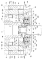
- the hydraulic shock absorber 1 has a double cylinder structure including an outer cylinder 2 (cylinder) and an inner cylinder 3.
- a reservoir 4 is formed between the outer cylinder 2 and the inner cylinder 3.
- a piston 5 is slidably inserted inside the inner cylinder 3, and the inside of the inner cylinder 3 is divided into a first chamber 3A and a second chamber 3B by the piston 5.
- the piston 5 is fixed to one end of the piston rod 7 by a nut 6.
- the piston rod 7 extends to the outside of the inner cylinder 3 through the rod guide 8 and the oil seal 9 mounted on the upper ends of the outer cylinder 2 and the inner cylinder 3.
- the piston 5 has oil passages 10 and 11 for communicating between the first chamber 3A and the second chamber 3B.
- a check valve 12 On the surface of the piston 5 on the first chamber 3 ⁇ / b> A side, a check valve 12 that allows only fluid flow from the second chamber 3 ⁇ / b> B side to the first chamber 3 ⁇ / b> A side in the oil passage 10 is provided.
- the hydraulic shock absorber 1 includes a base valve 14 that is provided at the lower end portion of the inner cylinder 3 and separates the second chamber 3B and the reservoir 4.
- the base valve 14 includes oil passages 15 and 16 that allow the second chamber 3B and the reservoir 4 to communicate with each other.
- the base valve 14 includes a check valve 17 that allows only the fluid to flow from the reservoir 4 side to the second chamber 3B side in the oil passage 15.
- the base valve 14 is opened when the pressure of the oil liquid on the second chamber 3B side reaches a predetermined pressure, and the base valve 14 relieves the oil liquid on the second chamber 3B side to the reservoir 4 side through the oil passage 16.
- an oil liquid is sealed as a working fluid inside the inner cylinder 3, and an oil liquid and a gas are sealed inside the reservoir 4.
- the hydraulic shock absorber 1 includes a separator tube 19 provided between the outer cylinder 2 and the inner cylinder 3. Seal members 20 are mounted between the upper and lower ends of the inner periphery of the separator tube 19 and the outer periphery of the inner cylinder 3. Thereby, an annular oil passage 21 is formed between the inner cylinder 3 and the separator tube 19.
- the annular oil passage 21 is communicated with the first chamber 3 ⁇ / b> A by an oil passage 22 provided at the upper end portion of the inner cylinder 3.
- a small-diameter opening 23 is provided at the lower end portion of the separator tube 19.
- the outer cylinder 2 is provided with a large-diameter opening 24 disposed corresponding to the opening 23.
- a damping force generation mechanism 25 is attached to the opening 24 of the outer cylinder 2.
- the damping force generation mechanism 25 has a cylindrical case 26 attached to the opening 24.
- a pilot type (back pressure type) main damping valve 27 and a solenoid bubble 28 which is a pressure control valve for controlling the valve opening pressure of the main damping valve 27 are fixed to the case 26 by nuts 29.
- the main damping valve 27 and the solenoid valve 28 are connected to the opening 23 and function to generate a damping force by controlling the flow of the oil liquid from the opening 23 to the reservoir 4.
- the main damping valve 27 is opened by bending under the pressure of the oil liquid on the opening 23 side, and the disk valve 30 that is a main valve that causes the oil liquid on the opening 23 side to flow to the reservoir 4 side.
- the back pressure chamber 31 is formed on the back side of the disc valve 30 and applies the internal pressure on the back side of the disc valve 30 in the closing direction of the disc valve 30. Further, a sub passage 33 is connected to the opening 23 through a fixed orifice 32. The auxiliary passage 33 is connected to the solenoid valve 28 and communicates with the back pressure chamber 31 via the passage 33A.
- the processing device 41 includes an axial force applying portion 42 that applies an axial force to an internal machine component (hereinafter referred to as an internal machine component) of the hydraulic shock absorber 1 including the rod guide 8, the base valve 14, and the like, and an opening of the outer cylinder 2. And a machining head 43 that applies a machining force to the end portion.
- the axial force imparting portion 42 is formed in a substantially cylindrical shape and is disposed on the same axis L1 (hereinafter referred to as the axis L1) with respect to the outer cylinder 2 and is capable of moving in the vertical direction on the axis L1. And a holding jig 45 attached to the lower end portion of the shaft portion 44.
- the holding jig 45 is formed in a cylindrical shape and is fitted into a jig mounting hole 46 that is opened in the lower end portion end surface 44A of the shaft portion 44, and is formed in a cylindrical shape with an annular lower end surface. It has a pressing portion 48 that comes into contact with the internal machine parts, and a flange portion 49 that is formed at the boundary portion between the mounting portion 47 and the pressing portion 48 and is received by the lower end surface 44A of the shaft portion 44.
- the pressing jig 45 is configured such that the outer peripheral surface of the mounting portion 47 is pressed by the tip of the fixing bolt 50 that is screwed to the lower end portion of the shaft portion 44 (two in FIG. 2). Thus, the structure is attached to the lower end portion of the shaft portion 44.
- the outer diameter of the mounting portion 47 is set larger than the outer diameter of the presser portion 48.
- a first inclined surface 57 that is inclined at a predetermined angle with respect to the axis L1 is formed on the axis L1 side of the lower end portion of each elevating part 52. Thereby, the lower end part of each raising / lowering part 52 is formed in a wedge shape.
- the lower guide portion 59 has a bearing mounting hole 59A having a rectangular cross section in which a bearing member 53B for guiding each elevating portion 52 is mounted.
- the guide part 54 can guide each raising / lowering part 52 to an up-down direction with a pair of bearing member 53A, 53B arrange
- the processing unit 56 includes a base 62 that is formed in a disc shape and is supported by the guide unit 54, and each slide base 63 provided corresponding to each roller 55.
- the slide base 63 is configured by a member formed in a substantially U-shape in which the opening 63A is directed to the axis L1 side (the right side in FIG. 2).
- the lower part of the slide base 63 is formed in the upper surface of the base 62 and extends in the direction perpendicular to the axis L1 (left and right direction in FIG.
- a stroke groove 65 having a predetermined length extending in a direction orthogonal to the axis L1 is formed on the lower surface of the slide base 63.
- a tip end portion of a set screw 66 screwed to the base 62 projects into the stroke groove 65.
- both ends of the stroke groove 65 are abutted against the set screw 66 to restrict the movement of the slide base 63.
- the stroke amount of the slide base 63 is determined by the length of the stroke groove 65.
- a roller support shaft 67 that supports the roller 55 so as to be rotatable around a rotation axis parallel to the axis L1 is attached to the slide base 63.
- a flange portion 67 ⁇ / b> A embedded in the lower portion of the slide base 63 is formed at the lower end portion of the roller support shaft 67.
- the roller 55 has a pair of bearings 69 (roller bearings) provided between the roller 55 and the slide base 63 with a space in the vertical direction, and a space in the vertical direction between the roller 55 and the roller support shaft 67. Thus, a pair of bearings 70 are rotated (spinned) around the roller support shaft 67.
- the slide table 63 is formed by a second inclined surface 71 having a surface directed outward and having an inclination angle corresponding to the first inclined surface 57 of the elevating unit 52.
- the slide base 63 is urged in a direction away from the axis L1 (left direction in FIG. 2) by an urging means (not shown).
- the second inclined surface 71 of the slide base 63 is configured to be slidably pressed against the first inclined surface 57 of the elevating unit 52. Therefore, the slide base 63 is moved rightward in FIG. 2 toward the axis L1 when the elevating part 52 is moved downward.
- the elevating part 52 is moved upward, the slide base 63 is moved to the axis L1.
- it is moved in the direction away from it (left direction in FIG. 2).
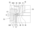
- each roller 55 is rotated (revolved) around the axis L1 at a predetermined rotation speed, and each elevating part 52 is moved downward at a predetermined speed. Then, each roller 55 is moved horizontally (to reduce the revolution radius) from the initial position shown on the left side of the axis L1 in FIG. 2 to the first position shown in FIG. 3 toward the axis L1 at a predetermined speed. In this first position, the contact portion 68A1 of the roller 68 with the cylinder 2 is outside the radial position of the opening end 2A of the cylinder.
- the opening end 2A means the tip, and the opening end 2B means the tip side portion.
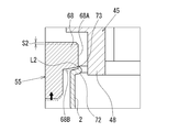
- each roller 55 is moved upward by a distance S ⁇ b> 2 (side to escape from the caulking portion 72). Accordingly, each roller 55 is moved (released) from the first position to the second position shown in FIG.
- the distance S2 can be set as appropriate based on the thickness, material, and the like of the opening end of the outer cylinder 2.
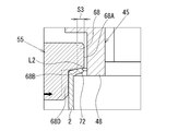
- each roller 55 is released upward in the escape process, the occurrence of flash 73 (projection) at the tip of the caulking portion 72 is suppressed. Further, in the third position, the deformation due to the caulking process can be corrected by pressing the outer periphery on the end side of the cylinder 2 with the outer peripheral surface 68D having a smaller diameter than the outer peripheral surface 68A.
- each roller 55 is moved in the radial direction of the outer cylinder 2 while rotating around the axis L ⁇ b> 1 of the outer cylinder 2, and the opening of the outer cylinder 2 is formed by the molding portion 68 on the outer periphery of each roller 55.
- the first caulking process that bends inward over the distance between the rollers 55 and the first position.
- the first caulking step by moving the roller 55 from the second position to the third position by the distance S3 from the second position to the third position.
- a second caulking step for caulking the caulking portion 72 bent in the direction.
- the final caulking portion 72 has a larger thickness than when it does not escape. Thereby, the strength of the caulking portion 72 can be improved.
- the processing head 43 has two rollers 55, but the number of rollers 55 may be one or three, for example.
- second embodiment for caulking the opening end portion of the outer cylinder 2 using the processing apparatus 1 described above.
- the second embodiment is the same from the [positioning step] to the [first caulking step] in comparison with the first embodiment described above.
- descriptions of the same steps as the first embodiment, that is, the positioning step and the first caulking step are omitted.
- each roller 55 is moved upward by a distance S4 (the side escaping from the caulking portion 72).
- each roller 55 is moved (released) from the first position shown in FIG. 3 to the fourth position shown in FIG.
- the moving distance S4 of each roller 55 in the escape process of the second process is longer than the moving distance S2 of each roller 55 in the escape process of the first process (S4> S2), and each roller in the fourth position.
- the height in the axial direction of the 55 ridgeline L2 is equal to or higher than the height (position) of the beam 73.
- the distance S4 can be appropriately set based on the thickness, material, and the like of the opening end portion of the outer cylinder 2.
- each elevating part 52 is moved downward at a predetermined speed, and each roller 55 is moved from the fourth position shown in FIG. 6 to the fifth position shown in FIG. 7 toward the axis L1 at a predetermined speed.
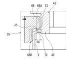
- the fifth position of each roller 55 is a position where each roller 55 has been moved from the fourth position toward the axis L1 by a distance S5, and the inclined surface 68B (opposing surface) of the forming portion 68 of each roller 55 at the fourth position. The surface) is located immediately above the beam 73.
- each roller 55 is moved from the first position shown in FIG. 3 to FIG. It may be moved to the fifth position shown in FIG. In this case, the movement time of each roller 55 can be shortened.
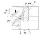
- each roller 55 is moved downward (side closer to the caulking portion 72) by a distance S6. Accordingly, each roller 55 is moved from the fifth position shown in FIG. 7 to the sixth position shown in FIG. In this sixth position, each roller 55 has an outer peripheral surface 68A (ridge line L2) positioned inward (axis L1 side) from the caulking portion 72, and therefore the flash 73 of the caulking portion 72 is an inclined surface of each roller 55. While being crushed by 68B (opposing surface), the opening end portion of the outer cylinder 2 bent inward in the first caulking step is deformed along the inclined surface 68B of each roller 55. As a result, an axial force is applied to the internal machine component by the caulking portion 72, and the occurrence of flash 73 (protrusion) at the tip of the caulking portion 72 can be suppressed.
- 68A ridge line L2
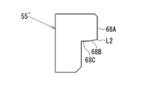
- roller 55 'shown by FIG. 9 can be used.
- the roller 55 ' is inward of the inclined surface 68B (opposing surface), in other words, on the opposite side (left side and lower side in FIG. 9) to the outer peripheral surface 68A (ridge line L2), with respect to the outer peripheral surface 68A and the axis L1.
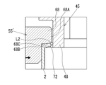
- a vertical horizontal plane 68C When the above-described second caulking step is performed by moving the machining head 43 including such a roller 55 'downward by a distance S6, as shown in FIG. 10, the outer peripheral edge of the opening end of the outer cylinder 2 The portion can be formed on a plane perpendicular to the axis of the outer cylinder 2. Thereby, axial force can be increased more reliably.
- the horizontal surface 68C may be a surface having a smaller inclination angle than the inclined surface 68B.
Landscapes
- Engineering & Computer Science (AREA)
- General Engineering & Computer Science (AREA)
- Mechanical Engineering (AREA)
- Fluid-Damping Devices (AREA)
Abstract
【課題】径方向へ移動するローラによって開口端部をかしめるシリンダ装置の製造方法において、かしめ部の先端のばりの発生を抑制する。 【解決手段】各ローラ55を径方向へ移動させて外筒2の開口端部を全周に亘って内方へ曲げた後、各ローラ55を上方向へ移動させて逃がし、次に、各ローラ55を径方向へ移動させるので、各ローラ55を一旦逃がすことで、各ローラ55の外周面68Aは最初の移動によって形成されたばり73を越えて内方へ移動することが可能であり、その結果、かしめ部72の先端におけるばり73(突起)の発生を抑制することができる。
Description
本発明は、シリンダの管端がかしめ加工されるシリンダ装置の製造方法に関する。
例えば、二重筒構造であるシリンダ装置の外筒の開口端部(管端)をかしめて内筒に内機部品(ベースバルブ)を保持するための残留軸力を付与させる技術は、特許文献1に記載されている。しかしながら、特許文献1に記載の製造方法は、揺動カール型との干渉を回避することがシリンダ装置側に求められ、例えば、取付アイを備えるシリンダ装置への適用は困難である。そこで、同一の円周上に型としての3つのローラを等間隔で配置して、各ローラを該円周の中心線の回りに回転させながら、各ローラを該円周の半径方向へ向けて移動させて該円周の半径を縮径させることにより、外筒の開口端部をその全周に亘って内側へかしめるようにしたシリンダ装置の製造方法が実用化されている。
しかしながら、上述したローラを円周の半径方向内方へ移動させることで外筒の開口端部をかしめる製造方法では、材料の塑性流動によってかしめ部の先端にばり(突起)が形成される。このような、かしめ部の先端にばりが形成されたシリンダ装置では、ばりの外側部分に外部からのコンタミが溜まり易く、このコンタミがシール箇所からシリンダ内部に侵入する虞がある。
そこで本発明は、上記事情に鑑みてなされたもので、径方向へ移動するローラによって開口端部をかしめるシリンダ装置の製造方法において、かしめ部の先端のばりの発生を抑制することを課題としてなされたものである。
上記課題を解決するために、本発明のシリンダ装置の製造方法は、有底筒形のシリンダの開口端部に対してローラを前記シリンダの軸線を中心に回転させながら前記シリンダの径方向へ移動させて、前記ローラの外周によって前記シリンダの開口端部を内方へかしめることにより、前記シリンダの開口端部にかしめ部が形成されるシリンダ装置の製造方法であって、前記ローラを初期位置に位置決めさせる位置決め工程と、前記ローラを前記シリンダの軸線を中心に回転させながら、前記ローラを前記初期位置から第1位置まで前記シリンダの径方向へ移動させて、該ローラの外周によって、前記シリンダの開口端部を全周に亘って内方へ曲げる第1かしめ工程と、前記ローラを前記第1位置から第2位置まで前記シリンダの開口端部に対して逃げる側へ前記シリンダの軸線に沿って移動させる逃がし工程と、前記ローラを前記第2位置から第3位置まで前記シリンダの径方向へ移動させて、該ローラの外周によって、前記第1かしめ工程で曲げられた前記シリンダの開口端部を全周に亘って内方へかしめる第2かしめ工程と、を含むことを特徴とする。
本発明によれば、径方向へ移動するローラによって開口端部をかしめるシリンダ装置の製造方法において、かしめ部の先端のばりの発生を抑制することができる。
1 油圧緩衝器(シリンダ装置)、2 外筒(シリンダ)、55 ローラ、72 かしめ部
本発明の一実施形態を添付した図を参照して説明する。ここでは、図1に示される減衰力調整式油圧緩衝器1(シリンダ装置)の製造方法を説明する。なお、以下の説明において、便宜上、図1における上下方向を油圧緩衝器1の上下方向と定義する。
図1に示されるように、油圧緩衝器1は、外筒2(シリンダ)と内筒3とを備えた二重筒構造である。外筒2と内筒3との間にはリザーバ4が形成される。内筒3の内側にはピストン5が摺動可能に挿入されており、該ピストン5によって内筒3の内側が第1室3Aと第2室3Bとに分画される。
図1に示されるように、油圧緩衝器1は、外筒2(シリンダ)と内筒3とを備えた二重筒構造である。外筒2と内筒3との間にはリザーバ4が形成される。内筒3の内側にはピストン5が摺動可能に挿入されており、該ピストン5によって内筒3の内側が第1室3Aと第2室3Bとに分画される。
ピストン5は、ナット6によってピストンロッド7の一端に固定される。ピストンロッド7は、外筒2及び内筒3の上端部に装着されたロッドガイド8及びオイルシール9を貫通して内筒3の外部へ延びる。ピストン5は、第1室3A、第2室3B間を連通させる油路10、11を有する。ピストン5の第1室3A側の面には、油路10における第2室3B側から第1室3A側への油液の流通のみを許容する逆止弁12が設けられる。また、ピストン5の第2室3B側の面には、第1室3A側の油液の圧力が所定圧力に達した時に開弁して、第1室3A側の油液を油路11を通して第2室3B側へリリーフするディスクバルブ13が設けられる。
油圧緩衝器1は、内筒3の下端部に設けられて第2室3Bとリザーバ4とを分画するベースバルブ14を備える。ベースバルブ14は、第2室3Bとリザーバ4とを連通させる油路15、16を有する。また、ベースバルブ14は、油路15におけるリザーバ4側から第2室3B側への油液の流通のみを許容する逆止弁17を備える。さらに、ベースバルブ14は、第2室3B側の油液の圧力が所定圧力に達した時に開弁して、第2室3B側の油液を油路16を通してリザーバ4側へリリーフするディスクバルブ18を有する。なお、内筒3の内側には作動流体として油液が封入されて、リザーバ4の内側には油液及びガスが封入される。
油圧緩衝器1は、外筒2と内筒3との間に設けられるセパレータチューブ19を備える。セパレータチューブ19の内周の上下両端部と内筒3の外周との間には、シール部材20が装着される。これにより、内筒3とセパレータチューブ19との間には環状油路21が形成される。環状油路21は、内筒3の上端部分に設けられる油路22によって第1室3Aに連通される。セパレータチューブ19の下端部分には、小径の開口23が設けられる。また、外筒2には、開口23に対応して配置される大径の開口24が設けられる。そして、外筒2の開口24には、減衰力発生機構25が取り付けられる。
減衰力発生機構25は、開口24に装着される円筒形のケース26を有する。該ケース26には、パイロット型(背圧型)の主減衰バルブ27及び該主減衰バルブ27の開弁圧力を制御する圧力制御弁であるソレノイドバブル28がナット29によって固定される。主減衰バルブ27及びソレノイドバルブ28は、開口23に接続されて開口23からリザーバ4への油液の流れを制御して減衰力を発生させるように機能する。主減衰バルブ27は、開口23側の油液の圧力を受けて撓むことによって開弁して開口23側の油液をリザーバ4側へ流通させるメインバルブであるディスクバルブ30、及びディスクバルブ30の背面側に形成されて該ディスクバルブ30の背面側の内圧をディスクバルブ30の閉弁方向に作用させる背圧室31を備える。また、開口23には、固定オリフィス32を介して副通路33が接続される。該副通路33は、ソレノイドバルブ28に接続されて通路33Aを介して背圧室31に連通される。
次に、外筒2(シリンダ)の開口端部をかしめるための加工装置41を図2を参照して説明する。なお、図2においては、加工装置41を示すものであって、作動を説明のため、参考として、油圧緩衝器1の外筒2のみを図示している。実際に加工する際には、ピストンロッド7、ロッドガイド8及びオイルシール9等がセットされた状態で、加工装置41にセットされる。
まず、油圧緩衝器1は、対応する保持用治具によって、外筒2の開口端部が上方向へ開口される垂直姿勢で保持される。
加工装置41は、ロッドガイド8、ベースバルブ14等を含む油圧緩衝器1の内機部品(以下、内機部品)に対して軸力を付与する軸力付与部42と、外筒2の開口端部に対して加工力を付与する加工ヘッド43とを備える。軸力付与部42は、略円筒形に形成されるとともに外筒2に対して同一軸線L1(以下、軸線L1)上に配置されて該軸線L1上を上下方向へ移動可能な軸部44と、該軸部44の下端部に取り付けられる押え治具45とを有する。
まず、油圧緩衝器1は、対応する保持用治具によって、外筒2の開口端部が上方向へ開口される垂直姿勢で保持される。
加工装置41は、ロッドガイド8、ベースバルブ14等を含む油圧緩衝器1の内機部品(以下、内機部品)に対して軸力を付与する軸力付与部42と、外筒2の開口端部に対して加工力を付与する加工ヘッド43とを備える。軸力付与部42は、略円筒形に形成されるとともに外筒2に対して同一軸線L1(以下、軸線L1)上に配置されて該軸線L1上を上下方向へ移動可能な軸部44と、該軸部44の下端部に取り付けられる押え治具45とを有する。
押え治具45は、円筒形に形成されて軸部44の下端部端面44Aに開口する治具装着穴46に嵌合される装着部47と、円筒形に形成されて円環形の下端面が内機部品に当接される押え部48と、装着部47と押え部48との境界部分に形成されて軸部44の下端部端面44Aによって受け止められるフランジ部49とを有する。押え治具45は、軸部44の下端部に螺合された少なくとも1個(図2中には2個記載)の固定用ボルト50の先端部によって装着部47の外周面が押圧されることにより、軸部44の下端部に装着される構造になっている。なお、装着部47の外径は押え部48の外径よりも大きく設定される。
加工ヘッド43は、軸部44の図2における左右両側に一対で設けられて駆動機構(図示省略)の駆動によって軸線L1を回転中心に回転される各本体部51と、各本体部51に対応して設けられて駆動機構(図示省略)の駆動によって上下方向へ移動される各昇降部52と、各本体部51によって支持されて各昇降部52を上下方向へ案内する案内部54と、該案内部54によって支持されて2個の成形用ローラ55を有する加工部56とを備える。結果として、成形用ローラ55は、軸線L1を中心に公転する。各昇降部52は、軸線L1に沿って上下方向へ延びて断面が矩形の部材によって形成される。また、各昇降部52の下端部の軸線L1側には、軸線L1に対して既定角度で傾斜される第1傾斜面57が形成される。これにより、各昇降部52の下端部は、楔形に形成される。
案内部54は、各昇降部52に対応して設けられて各本体部51の下端面に取り付けられる各上案内部58と、各上案内部58によって支持される円環形の下案内部59とによって構成される。各上案内部58は、L字形に形成されてボルト60によって各本体部51の下端部に固定される。また、各上案内部58は、各昇降部52を案内するための軸受部材53Aが装着される断面が矩形の軸受取付穴58Aを有する。下案内部59は、ボルト61によって各上案内部58の下端部に固定される。また、下案内部59は、各昇降部52を案内するための軸受部材53Bが装着される断面が矩形の軸受取付穴59Aを有する。そして、案内部54は、上下方向に間隔をあけて配置された一対の軸受部材53A、53Bによって各昇降部52を上下方向へ案内することができる。
加工部56は、円板形に形成されて案内部54によって支持される基台62と、各ローラ55に対応して設けられる各スライド台63とを有する。なお、加工部56は、図2において、軸線L1に対して左右対称に構成されているので、ここでは、軸線L1の左側部分のみを説明する。スライド台63は、開口部63Aが軸線L1側(図2における右側)に向けられた略コ字形に形成された部材によって構成される。スライド台63の下部は、基台62の上面に形成されて軸線L1に対して直交する方向(図2における左右方向)へ延びる下案内溝64によって、軸線L1に対して直交する方向(外筒2の径方向)へ案内される。また、スライド台63の上部は、下案内部59の下面に形成されて軸線L1に対して直交する方向(図2における左右方向)へ延びる上案内溝74によって、軸線L1に対して直交する方向(外筒2の径方向)へ案内される。
スライド台63の下面には、軸線L1に対して直交する方向へ延びる所定長さのストローク溝65が形成される。該ストローク溝65には、基台62に螺合された止めねじ66の先端部が突出される。これにより、ストローク溝65の両端部が止めねじ66に突き当てられることによりスライド台63の移動が規制される。換言すると、ストローク溝65の長さによってスライド台63のストローク量が決定される構造になっている。また、スライド台63には、ローラ55を軸線L1に対して平行な回転軸の回りに回転可能に支持するローラ支持軸67が取り付けられる。なお、ローラ支持軸67の下端部には、スライド台63の下部に埋設されたフランジ部67Aが形成される。
ローラ55は、上部にフランジ形状の成形部68を有する。該成形部68は、軸線L1に対して平行な面によって形成される外周面68A(外周)と、該外周面68Aの下側の円形の稜線L2を介して外周面68Aに連続する傾斜面68B(端面)とを有する。該傾斜面68Bは、軸線L1に垂直な平面に対して所定角度で傾斜されており、稜線L2から下方向へ向けて縮径される。ローラ55は、ローラ55とスライド台63との間に上下方向へ間隔をあけて一対で設けられる軸受69(ローラ軸受)、及びローラ55とローラ支持軸67との間に上下方向へ間隔をあけて一対で設けられる軸受70によって、ローラ支持軸67の回りに回転(自転)される構造になっている。
スライド台63は、外方に向けられた面が昇降部52の第1傾斜面57に対応する傾斜角度を有する第2傾斜面71によって形成される。また、スライド台63は、図示を省略する付勢手段によって軸線L1から離れる方向(図2における左方向)へ付勢される。これにより、スライド台63の第2傾斜面71は、昇降部52の第1傾斜面57に摺動可能に押し付けられるように構成される。したがって、スライド台63は、昇降部52を下方向へ移動させると、軸線L1に向かって図2における右方向へ移動されて、他方で、昇降部52を上方向へ移動させると、軸線L1に対して離れる方向(図2における左方向)へ移動される。
次に、上述した加工装置1を使用して外筒2の開口端部をかしめ加工する一手順(第1の実施の形態)を説明する。
まず、保持用治具によって油圧緩衝器1を外筒2の開口端部が上方向へ開口される垂直姿勢で保持する。
まず、保持用治具によって油圧緩衝器1を外筒2の開口端部が上方向へ開口される垂直姿勢で保持する。
[位置決め工程]
次に、軸部44を下方向へ移動させて、軸部44に装着された押え治具45によって、ロッドガイド8、オイルシール9等の内機部品に既定の軸力を付与させる。これと同時に、加工ヘッド43を、下方向へ移動させて図2の軸線L1の左側に示される初期位置に位置決めさせる。この初期位置では、内機部品(押え治具45の押え部48の下端面位置)から外筒2の開口端部(かしめ代)の端面位置までの軸線L1方向への距離をG、各ローラ55の外周面68Aと傾斜面68Bとの間の稜線L2から外筒2の開口端部の端面位置までの軸線L1方向への距離をH、及び外筒の板厚をtとすると、G>H>tである。
次に、軸部44を下方向へ移動させて、軸部44に装着された押え治具45によって、ロッドガイド8、オイルシール9等の内機部品に既定の軸力を付与させる。これと同時に、加工ヘッド43を、下方向へ移動させて図2の軸線L1の左側に示される初期位置に位置決めさせる。この初期位置では、内機部品(押え治具45の押え部48の下端面位置)から外筒2の開口端部(かしめ代)の端面位置までの軸線L1方向への距離をG、各ローラ55の外周面68Aと傾斜面68Bとの間の稜線L2から外筒2の開口端部の端面位置までの軸線L1方向への距離をH、及び外筒の板厚をtとすると、G>H>tである。
[第1かしめ工程]
次に、加工ヘッド43を軸線L1を中心に回転させて各ローラ55を軸線L1の回りに既定の回転速度で回転(公転)させながら、各昇降部52を既定の速度で下方向へ移動させて、各ローラ55を図2の軸線L1の左側に示される初期位置から図3に示される第1位置まで既定の速度で軸線L1に向けて水平(公転半径が小さくなるよう)に移動させる。この第1位置は、ローラ68のシリンダ2との当接部68A1がシリンダの開口端2Aの径方向位置より外側となる。この開口端2Aは、先端を意味し、開口端部2Bは先端側の部分を意味する。この各ローラ55の第1位置は、各ローラ55の外周面68Aが外筒2に当接されてから各ローラ55が軸線L1へ向けて距離S1だけ移動された位置である。これにより、外筒2の開口端部は、内機部品の上端(押え治具45の押え部48の下端)から上の部分が、全周に亘って内方へ曲げられる。以下、開口端部2Bの内方へ曲げられた部分を必要に応じてかしめ部72と呼ぶ。
次に、加工ヘッド43を軸線L1を中心に回転させて各ローラ55を軸線L1の回りに既定の回転速度で回転(公転)させながら、各昇降部52を既定の速度で下方向へ移動させて、各ローラ55を図2の軸線L1の左側に示される初期位置から図3に示される第1位置まで既定の速度で軸線L1に向けて水平(公転半径が小さくなるよう)に移動させる。この第1位置は、ローラ68のシリンダ2との当接部68A1がシリンダの開口端2Aの径方向位置より外側となる。この開口端2Aは、先端を意味し、開口端部2Bは先端側の部分を意味する。この各ローラ55の第1位置は、各ローラ55の外周面68Aが外筒2に当接されてから各ローラ55が軸線L1へ向けて距離S1だけ移動された位置である。これにより、外筒2の開口端部は、内機部品の上端(押え治具45の押え部48の下端)から上の部分が、全周に亘って内方へ曲げられる。以下、開口端部2Bの内方へ曲げられた部分を必要に応じてかしめ部72と呼ぶ。
図3に示されるように、各ローラ55の第1位置では、かしめ部72の先端に肉厚部となるばり73(突起)が形成される。このばり73は、外筒2の開口端部の材料が塑性流動することにより形成されるものであり、各ローラ55の外周面68A側(図3における上側)へ突出する。また、各ローラ55の第1位置では、かしめ部72は、内機部品に軸力を付与させる方向に向けて十分な板厚が確保されている。
[逃がし工程]
次に、加工ヘッド43、延いては、各ローラ55を上方向(かしめ部72に対して逃げる側)へ距離S2だけ移動させる。これにより、各ローラ55は、第1位置から図4に示される第2位置まで移動される(逃がされる)。なお、距離S2は、外筒2の開口端部の板厚、材質等に基づいて適宜設定することが可能である。
次に、加工ヘッド43、延いては、各ローラ55を上方向(かしめ部72に対して逃げる側)へ距離S2だけ移動させる。これにより、各ローラ55は、第1位置から図4に示される第2位置まで移動される(逃がされる)。なお、距離S2は、外筒2の開口端部の板厚、材質等に基づいて適宜設定することが可能である。
[第2かしめ工程]
次に、各昇降部52を既定の速度で下方向へ移動させて、各ローラ55を図4に示される第2位置から図5に示される第3位置まで既定の速度で軸線L1に向けて水平に(公転半径が小さくなるように)移動させる。この各ローラ55の第3位置は、各ローラ55が第2位置から軸線L1へ向けて距離S3だけ移動された位置であり、第3位置における各ローラ55のは、かしめ部72の先端よりも内方(軸線L1側)に位置される。これにより、第1かしめ工程で内方へ曲げられたかしめ部72がかしめられて、内機部品に軸力が付与される。また、逃がし工程で各ローラ55を上方向へ逃がしたことにより、かしめ部72の先端におけるばり73(突起)の発生が抑制される。
また、第3位置においては、外周面68Aより小径の小径外周面68Dにより、シリンダ2の端部側の外周を押圧することで、かしめ加工による変形を修正できる。
上述した実施形態によれば、各ローラ55を外筒2の軸線L1の回りに回転させながら外筒2の径方向へ移動させて、各ローラ55の外周の成形部68によって外筒2の開口端部を内方へかしめる油圧緩衝器1の製造方法において、内機部品から外筒2の開口端部の端面位置までの軸線L1方向への距離をG、各ローラ55の外周面68Aと傾斜面68Bとの間の稜線L2から外筒2の開口端部の端面位置までの軸線L1方向への距離をH、及び外筒2の板厚をtと定義した時に、G>H>tとなるような初期位置に各ローラ55を位置決めする位置決め工程と、各ローラ55を初期位置から第1位置まで軸線L1に向けて距離S1だけ移動させて、外筒2の開口端部を全周に亘って内方へ曲げる第1かしめ工程と、各ローラ55を第1位置から距離S2だけ上方向へ移動させて第2位置まで逃がす逃がし工程と、各ローラ55を第2位置から第3位置まで軸線L1へ向けて距離S3だけ移動させることにより、第1かしめ工程で内方へ曲げられたかしめ部72をかしめる第2かしめ工程と、の各工程を含む。
したがって、第1かしめ工程では、距離Hを板厚tと同程度に設定することにより、内機部品へ付与させる軸力を確保することができる。そして、第1かしめ工程によって軸力を確保した後、逃がし工程によって各ローラ55をかしめ部72から逃がして加工圧力を一旦解放させて、その後、各ローラ55を軸線L1に向けて移動させることにより、開口端部(かしめ部72)をかしめるので、各ローラ55の外周面68Aは第1かしめ工程によって形成されたばり73を越えて内方へ移動することが可能であり、その結果、かしめ部72の先端におけるばり73(突起)の発生を抑制することができる。
このように、外筒2の開口端部に突起が形成されることを抑制することができるので、外部からのコンタミの滞留を抑制することができる。また、外筒2の開口端部に対して径方向から工具(ローラ55)を接近させて加工するため、例えば、揺動カール型を使用する工具を軸方向へ移動させる製造方法と比較して、内機部品への負荷を軽減することが可能である。その結果、より低い強度の内機部品を採用することが可能であり、製造コストを削減することができる。
また、逃がし工程によって各ローラ55をかしめ部72から逃がすことにより、逃がさない場合と比較して、最終的なかしめ部72の板厚が大きくなる。これにより、かしめ部72の強度を向上させることができる。
なお、本実施形態では、加工ヘッド43は、2個のローラ55を有しているが、ローラ55の数量は、例えば、1個あるいは3個とすることができる。
次に、上述した加工装置1を使用して外筒2の開口端部をかしめ加工する他の手順(第2の実施形態)を説明する。
なお、第2の実施形態は、上述した第1の実施形態との比較で[位置決め工程]から[第1かしめ工程]まで同一である。以下の第2の実施形態の説明では、第1実施形態と同一の工程、すなわち、位置決め工程および第1かしめ工程の説明を省略する。
なお、第2の実施形態は、上述した第1の実施形態との比較で[位置決め工程]から[第1かしめ工程]まで同一である。以下の第2の実施形態の説明では、第1実施形態と同一の工程、すなわち、位置決め工程および第1かしめ工程の説明を省略する。
[逃がし工程]
第1かしめ工程完了後、加工ヘッド43、延いては、各ローラ55を上方向(かしめ部72に対して逃げる側)へ距離S4だけ移動させる。これにより、各ローラ55は、図3に示される第1位置から図6に示される第4位置まで移動される(逃がされる)。なお、第2プロセスの逃がし工程での各ローラ55の移動距離S4は、第1プロセスの逃がし工程での各ローラ55の移動距離S2よりも長く(S4>S2)、且つ第4位置における各ローラ55の稜線L2の軸線方向高さは、ばり73の高さ(位置)以上である。また、距離S4は、外筒2の開口端部の板厚、材質等に基づいて適宜設定することが可能である。
第1かしめ工程完了後、加工ヘッド43、延いては、各ローラ55を上方向(かしめ部72に対して逃げる側)へ距離S4だけ移動させる。これにより、各ローラ55は、図3に示される第1位置から図6に示される第4位置まで移動される(逃がされる)。なお、第2プロセスの逃がし工程での各ローラ55の移動距離S4は、第1プロセスの逃がし工程での各ローラ55の移動距離S2よりも長く(S4>S2)、且つ第4位置における各ローラ55の稜線L2の軸線方向高さは、ばり73の高さ(位置)以上である。また、距離S4は、外筒2の開口端部の板厚、材質等に基づいて適宜設定することが可能である。
[第2かしめ工程(ローラ移動工程)]
次に、各昇降部52を既定の速度で下方向へ移動させて、各ローラ55を図6に示される第4位置から図7に示される第5位置まで既定の速度で軸線L1に向けて水平に移動させる。この各ローラ55の第5位置は、各ローラ55が第4位置から軸線L1へ向けて距離S5だけ移動された位置であり、第4位置における各ローラ55の成形部68の傾斜面68B(対向面)がばり73の直上に位置するような位置である。なお、第2プロセスにおいて、各ローラ55がばり73に接触しないことを条件に、逃がし工程とローラ移動工程とを同時に実施する、すなわち、各ローラ55を図3に示される第1位置から図7に示される第5位置へ移動させてもよい。この場合、各ローラ55の移動時間を短縮することができる。
次に、各昇降部52を既定の速度で下方向へ移動させて、各ローラ55を図6に示される第4位置から図7に示される第5位置まで既定の速度で軸線L1に向けて水平に移動させる。この各ローラ55の第5位置は、各ローラ55が第4位置から軸線L1へ向けて距離S5だけ移動された位置であり、第4位置における各ローラ55の成形部68の傾斜面68B(対向面)がばり73の直上に位置するような位置である。なお、第2プロセスにおいて、各ローラ55がばり73に接触しないことを条件に、逃がし工程とローラ移動工程とを同時に実施する、すなわち、各ローラ55を図3に示される第1位置から図7に示される第5位置へ移動させてもよい。この場合、各ローラ55の移動時間を短縮することができる。
[第2かしめ工程(ばり潰し工程)]
次に、加工ヘッド43、延いては、各ローラ55を下方向(かしめ部72に対して近づく側)へ距離S6だけ移動させる。これにより、各ローラ55は、図7に示される第5位置から図8に示される第6位置まで移動される。この第6位置では、各ローラ55は、外周面68A(稜線L2)がかしめ部72よりも内方(軸線L1側)に位置されるため、かしめ部72のばり73が各ローラ55の傾斜面68B(対向面)によって押し潰されるとともに、第1かしめ工程で内方へ曲げられた外筒2の開口端部が各ローラ55の傾斜面68Bに沿って変形する。これにより、かしめ部72によって内機部品に軸力が付与され、さらに、かしめ部72の先端におけるばり73(突起)の発生を抑制することができる。
次に、加工ヘッド43、延いては、各ローラ55を下方向(かしめ部72に対して近づく側)へ距離S6だけ移動させる。これにより、各ローラ55は、図7に示される第5位置から図8に示される第6位置まで移動される。この第6位置では、各ローラ55は、外周面68A(稜線L2)がかしめ部72よりも内方(軸線L1側)に位置されるため、かしめ部72のばり73が各ローラ55の傾斜面68B(対向面)によって押し潰されるとともに、第1かしめ工程で内方へ曲げられた外筒2の開口端部が各ローラ55の傾斜面68Bに沿って変形する。これにより、かしめ部72によって内機部品に軸力が付与され、さらに、かしめ部72の先端におけるばり73(突起)の発生を抑制することができる。
なお、第2の実施形態を含む上記実施形態では、図9に示されるローラ55´を使用することができる。このローラ55´は、傾斜面68B(対向面)の内方、換言すると、外周面68A(稜線L2)とは反対側(図9における左側且つ下側)に、外周面68Aおよび軸線L1に対して垂直な水平面68Cを有する。このようなローラ55´を備える加工ヘッド43を下方向へ距離S6だけ移動させて上述した第2かしめ工程を行った場合、図10に示されるように、外筒2の開口端部の外周縁部を外筒2の軸線に対して垂直な平面に形成することができる。これにより、より確実に軸力を高めることが出来る。なお、水平面68Cは、傾斜面68Bより傾斜角のちいな面としてもよい。
Claims (6)
- 有底筒形のシリンダの開口端部に対してローラを前記シリンダの軸線を中心に公転させながら公転半径が小さくなる方向へ移動させて、前記ローラの外周によって前記シリンダの開口端部を内方へかしめることにより、前記シリンダの開口端部にかしめ部が形成されるシリンダ装置の製造方法であって、
前記ローラを前記シリンダの軸線を中心に公転させながら公転半径が小さくなる方向へ移動させて、前記シリンダの開口端部を全周に亘って径方向内方へ曲げ、前記ローラの前記シリンダとの当接部が、曲げられた前記シリンダの開口端の径方向位置よりも外側となる第1位置までかしめる第1かしめ工程と、
前記ローラを前記シリンダの開口端部から軸方向に離間させるように移動させる逃がし工程と、
前記ローラによって、前記第1かしめ工程で前記シリンダの開口端に形成された厚肉部を全周に亘ってかしめる第2かしめ工程と、
を含むことを特徴とするシリンダ装置の製造方法。 - 前記ローラーの外周側の前記シリンダ側の端面に、該ローラーの中心に向けて前記シリンダ側に近づくように傾斜した傾斜面を設け、
前記第2かしめ工程では、前記ローラを公転半径が小さくなる方向へ移動させ、前記傾斜面により、前記シリンダの開口端に形成された厚肉部を全周に亘ってかしめることを特徴とする請求項1に記載のシリンダ装置の製造方法。 - 前記ローラの外周側の前記シリンダ側の端面に、該ローラの中心に向けて前記シリンダ側に近づくように傾斜した傾斜面を設け、
前記第2かしめ工程では、前記ローラを前記シリンダ側に向けて軸方向に移動させ、該ローラの端面により、前記シリンダの開口端に形成された厚肉部を全周に亘ってかしめることを特徴とする請求項1に記載のシリンダ装置の製造方法。 - 前記ローラの外周側の前記シリンダ側の端面に、該ローラの中心に向けて前記シリンダ側に近づくように傾斜した傾斜面を設けたことを特徴とする請求項3に記載のシリンダ装置の製造方法。
- 前記ローラの傾斜面の内周側に該傾斜面より傾斜角の小さな内側端面を設け、前記第2かしめ工程で前記傾斜面と前記内側端面とで前記シリンダの開口端部をかしめることを特徴とする請求項4に記載のシリンダ装置の製造方法。
- 前記ローラの外周側の前記傾斜面より内周側に前記ローラの外周より小径の小径外周面を設け、第2かしめ工程で前記小径外周面により前記シリンダ側外周面を押圧することを特徴とする請求項2乃至5のいずれかに記載のシリンダ装置の製造方法。
Applications Claiming Priority (2)
| Application Number | Priority Date | Filing Date | Title |
|---|---|---|---|
| JP2012-043767 | 2012-02-29 | ||
| JP2012043767 | 2012-02-29 |
Publications (1)
| Publication Number | Publication Date |
|---|---|
| WO2013129589A1 true WO2013129589A1 (ja) | 2013-09-06 |
Family
ID=49082780
Family Applications (1)
| Application Number | Title | Priority Date | Filing Date |
|---|---|---|---|
| PCT/JP2013/055459 Ceased WO2013129589A1 (ja) | 2012-02-29 | 2013-02-28 | シリンダ装置の製造方法 |
Country Status (2)
| Country | Link |
|---|---|
| JP (1) | JPWO2013129589A1 (ja) |
| WO (1) | WO2013129589A1 (ja) |
Cited By (5)
| Publication number | Priority date | Publication date | Assignee | Title |
|---|---|---|---|---|
| CN104084467A (zh) * | 2014-06-30 | 2014-10-08 | 广州海鸥卫浴用品股份有限公司 | 一种管材口部旋压翻边装置 |
| CN106734455A (zh) * | 2017-01-23 | 2017-05-31 | 王安基 | 翻边装置及翻边机 |
| WO2019134283A1 (zh) * | 2018-01-05 | 2019-07-11 | 深圳市新沧海机械有限公司 | 充气翻边机 |
| CN112547947A (zh) * | 2020-11-19 | 2021-03-26 | 湖南三泰新材料股份有限公司 | 复合坯料外管旋压缩口设备 |
| EP4119249A1 (en) * | 2021-07-14 | 2023-01-18 | DRiV Automotive Inc. | Roller press assembly and method |
Citations (5)
| Publication number | Priority date | Publication date | Assignee | Title |
|---|---|---|---|---|
| US3863740A (en) * | 1971-06-02 | 1975-02-04 | Girling Ltd | Seal for hydraulic damper |
| JPS5281060A (en) * | 1975-12-29 | 1977-07-07 | Tokico Ltd | Method of forming cylinder end |
| JP2001105062A (ja) * | 1999-10-01 | 2001-04-17 | Saginomiya Seisakusho Inc | かしめ結合工具およびかしめ結合方法 |
| JP2006275149A (ja) * | 2005-03-29 | 2006-10-12 | Hitachi Ltd | シリンダ装置及び管端部のかしめ方法 |
| JP2008012572A (ja) * | 2006-07-07 | 2008-01-24 | Honda Motor Co Ltd | ローラヘミング装置 |
-
2013
- 2013-02-28 WO PCT/JP2013/055459 patent/WO2013129589A1/ja not_active Ceased
- 2013-02-28 JP JP2014502378A patent/JPWO2013129589A1/ja active Pending
Patent Citations (5)
| Publication number | Priority date | Publication date | Assignee | Title |
|---|---|---|---|---|
| US3863740A (en) * | 1971-06-02 | 1975-02-04 | Girling Ltd | Seal for hydraulic damper |
| JPS5281060A (en) * | 1975-12-29 | 1977-07-07 | Tokico Ltd | Method of forming cylinder end |
| JP2001105062A (ja) * | 1999-10-01 | 2001-04-17 | Saginomiya Seisakusho Inc | かしめ結合工具およびかしめ結合方法 |
| JP2006275149A (ja) * | 2005-03-29 | 2006-10-12 | Hitachi Ltd | シリンダ装置及び管端部のかしめ方法 |
| JP2008012572A (ja) * | 2006-07-07 | 2008-01-24 | Honda Motor Co Ltd | ローラヘミング装置 |
Cited By (6)
| Publication number | Priority date | Publication date | Assignee | Title |
|---|---|---|---|---|
| CN104084467A (zh) * | 2014-06-30 | 2014-10-08 | 广州海鸥卫浴用品股份有限公司 | 一种管材口部旋压翻边装置 |
| CN106734455A (zh) * | 2017-01-23 | 2017-05-31 | 王安基 | 翻边装置及翻边机 |
| CN106734455B (zh) * | 2017-01-23 | 2018-07-17 | 王安基 | 翻边装置及翻边机 |
| WO2019134283A1 (zh) * | 2018-01-05 | 2019-07-11 | 深圳市新沧海机械有限公司 | 充气翻边机 |
| CN112547947A (zh) * | 2020-11-19 | 2021-03-26 | 湖南三泰新材料股份有限公司 | 复合坯料外管旋压缩口设备 |
| EP4119249A1 (en) * | 2021-07-14 | 2023-01-18 | DRiV Automotive Inc. | Roller press assembly and method |
Also Published As
| Publication number | Publication date |
|---|---|
| JPWO2013129589A1 (ja) | 2015-07-30 |
Similar Documents
| Publication | Publication Date | Title |
|---|---|---|
| JPWO2013129589A1 (ja) | シリンダ装置の製造方法 | |
| JP2014069210A (ja) | チューブの加工方法及び緩衝器 | |
| JP2014069210A5 (ja) | ||
| KR102139397B1 (ko) | 튜브 및 완충기 | |
| US10247269B2 (en) | Piston manufacturing device, piston manufacturing method, piston and disc brake | |
| US20080314113A1 (en) | Processing method of tube body, manufacturing method of cylinder device and cylinder device manufactured by the same | |
| WO2018030195A1 (ja) | シリンダ装置、及びシリンダ装置の製造方法 | |
| JP6817103B2 (ja) | 緩衝器の製造方法および該製造方法に用いられるパンチ | |
| WO2024161456A1 (ja) | 底部成形方法、筒体、緩衝装置 | |
| WO2017122385A1 (ja) | シリンダ装置の製造方法 | |
| JP2016059931A (ja) | ギヤ部品の製造方法 | |
| JP2006275149A (ja) | シリンダ装置及び管端部のかしめ方法 | |
| US20050011245A1 (en) | Method and apparatus for working tube | |
| JP6681823B2 (ja) | 緩衝器の製造方法および該製造方法で用いる加締め治具 | |
| JP2011073057A (ja) | プレス加工装置および軸部規制装置 | |
| JP5287422B2 (ja) | カップ状部材の塑性加工装置及び方法 | |
| JP6768539B2 (ja) | シリンダ装置の製造方法およびシリンダ装置 | |
| JP2013244506A (ja) | チューブの加工装置及び加工方法 | |
| JP7104824B2 (ja) | シリンダ装置、及びシリンダ装置の製造方法 | |
| WO2018062176A1 (ja) | シリンダ装置の製造方法 | |
| JP2014181806A (ja) | 流体圧シリンダ及びその製造方法 | |
| JP2019005804A (ja) | シリンダ装置の製造方法およびシリンダ装置 | |
| JP2003254372A (ja) | 油圧緩衝器 | |
| JP2006132711A (ja) | 車輪支持用ハブユニットの製造方法 | |
| JP4919070B2 (ja) | 複筒式油圧緩衝器の製造方法 |
Legal Events
| Date | Code | Title | Description |
|---|---|---|---|
| 121 | Ep: the epo has been informed by wipo that ep was designated in this application |
Ref document number: 13754978 Country of ref document: EP Kind code of ref document: A1 |
|
| ENP | Entry into the national phase |
Ref document number: 2014502378 Country of ref document: JP Kind code of ref document: A |
|
| NENP | Non-entry into the national phase |
Ref country code: DE |
|
| 122 | Ep: pct application non-entry in european phase |
Ref document number: 13754978 Country of ref document: EP Kind code of ref document: A1 |