WO2013125627A1 - Bicyclette d'exercice - Google Patents
Bicyclette d'exercice Download PDFInfo
- Publication number
- WO2013125627A1 WO2013125627A1 PCT/JP2013/054308 JP2013054308W WO2013125627A1 WO 2013125627 A1 WO2013125627 A1 WO 2013125627A1 JP 2013054308 W JP2013054308 W JP 2013054308W WO 2013125627 A1 WO2013125627 A1 WO 2013125627A1
- Authority
- WO
- WIPO (PCT)
- Prior art keywords
- bicycle
- support shaft
- elastic
- bicycle trainer
- main body
- Prior art date
Links
Images


Classifications
-
- A—HUMAN NECESSITIES
- A63—SPORTS; GAMES; AMUSEMENTS
- A63B—APPARATUS FOR PHYSICAL TRAINING, GYMNASTICS, SWIMMING, CLIMBING, OR FENCING; BALL GAMES; TRAINING EQUIPMENT
- A63B22/00—Exercising apparatus specially adapted for conditioning the cardio-vascular system, for training agility or co-ordination of movements
- A63B22/06—Exercising apparatus specially adapted for conditioning the cardio-vascular system, for training agility or co-ordination of movements with support elements performing a rotating cycling movement, i.e. a closed path movement
- A63B22/0605—Exercising apparatus specially adapted for conditioning the cardio-vascular system, for training agility or co-ordination of movements with support elements performing a rotating cycling movement, i.e. a closed path movement performing a circular movement, e.g. ergometers
-
- A—HUMAN NECESSITIES
- A63—SPORTS; GAMES; AMUSEMENTS
- A63B—APPARATUS FOR PHYSICAL TRAINING, GYMNASTICS, SWIMMING, CLIMBING, OR FENCING; BALL GAMES; TRAINING EQUIPMENT
- A63B21/00—Exercising apparatus for developing or strengthening the muscles or joints of the body by working against a counterforce, with or without measuring devices
- A63B21/02—Exercising apparatus for developing or strengthening the muscles or joints of the body by working against a counterforce, with or without measuring devices using resilient force-resisters
- A63B21/026—Bars; Tubes; Leaf springs
-
- A—HUMAN NECESSITIES
- A63—SPORTS; GAMES; AMUSEMENTS
- A63B—APPARATUS FOR PHYSICAL TRAINING, GYMNASTICS, SWIMMING, CLIMBING, OR FENCING; BALL GAMES; TRAINING EQUIPMENT
- A63B69/00—Training appliances or apparatus for special sports
- A63B69/16—Training appliances or apparatus for special sports for cycling, i.e. arrangements on or for real bicycles
- A63B2069/161—Training appliances or apparatus for special sports for cycling, i.e. arrangements on or for real bicycles supports for the front of the bicycle
- A63B2069/162—Training appliances or apparatus for special sports for cycling, i.e. arrangements on or for real bicycles supports for the front of the bicycle for front fork or handlebar
-
- A—HUMAN NECESSITIES
- A63—SPORTS; GAMES; AMUSEMENTS
- A63B—APPARATUS FOR PHYSICAL TRAINING, GYMNASTICS, SWIMMING, CLIMBING, OR FENCING; BALL GAMES; TRAINING EQUIPMENT
- A63B69/00—Training appliances or apparatus for special sports
- A63B69/16—Training appliances or apparatus for special sports for cycling, i.e. arrangements on or for real bicycles
- A63B2069/164—Training appliances or apparatus for special sports for cycling, i.e. arrangements on or for real bicycles supports for the rear of the bicycle, e.g. for the rear forks
- A63B2069/165—Training appliances or apparatus for special sports for cycling, i.e. arrangements on or for real bicycles supports for the rear of the bicycle, e.g. for the rear forks rear wheel hub supports
-
- A—HUMAN NECESSITIES
- A63—SPORTS; GAMES; AMUSEMENTS
- A63B—APPARATUS FOR PHYSICAL TRAINING, GYMNASTICS, SWIMMING, CLIMBING, OR FENCING; BALL GAMES; TRAINING EQUIPMENT
- A63B26/00—Exercising apparatus not covered by groups A63B1/00 - A63B25/00
- A63B26/003—Exercising apparatus not covered by groups A63B1/00 - A63B25/00 for improving balance or equilibrium
Definitions
- the present invention relates to a bicycle trainer that can perform training using an actual bicycle that travels outdoors, and more particularly, to a bicycle trainer that is used for training with the bicycle wheel removed.
- a frame 62 on which a bicycle from which the front wheels are removed can be mounted is provided.
- the frame 62 includes a roller 64 that rotates while contacting a tire 74 of the rear wheel of the bicycle, and a roller 64.
- a bicycle trainer 60 provided with resistance applying means 66 that provides resistance to rotation is known (see Patent Document 1).
- a main body portion 82 that is stably installed on the ground, and a frame end fixing that supports and fixes the front frame end portion 95 of the bicycle 91 from which the rear wheel is removed.
- a bicycle training device 80 comprising means 85, a rotating body 84 linked to the driving device 92 of the bicycle 91 and rotating following the driving device 92, and a rotation braking device 88 for controlling the rotation of the rotating body 84.
- the front wheel of the bicycle 91 is removed from the fork end portion 95 together with the hub and supported and fixed to the fork end fixing means 85.
- Patent Document 1 The invention described in Patent Document 1 can be varied in a wide range from a state where no braking force to be applied to the braking disk 68 is received to a state where a predetermined braking force is received.
- the bicycle trainer 60 in which the front fork end portion 75 of the bicycle is supported and fixed to the hawk clamper 65 provided at the front rising portion 63 of the frame 62, the bicycle is moved back and forth like when actually running outdoors. Since it does not move or tilt left and right, there is a problem that it lacks a feeling of actual running as when actually driving a bicycle.
- Patent Document 2 the configuration in which the front fork end portion 95 of the bicycle 91 to be mounted is attached to the main body portion 82 via the fork end fixing means 85 is the same as that of Patent Document 1, and actually The problem of lacking a sense of actual driving like driving a bicycle outdoors has not been solved.
- the present invention has been made in view of the above-described circumstances, and an object of the present invention is to provide a bicycle trainer that provides a riding comfort as when a bicycle is actually driven outdoors.
- a bicycle trainer is a bicycle trainer that can perform training using a detachably mounted bicycle (21), and is a main body unit placed on a floor. (3), a support shaft (5) having one end loosely inserted into the main body and the other end fixed to a fork end support means (7) for supporting the fork end portion (23) of the bicycle; An elastic part (9) disposed so as to surround at least a part of the other end side from the longitudinal center of the shaft, and the bicycle is elastically deformed by a force applied from the fork end part. It is characterized by being able to move back and forth and tilt left and right.
- the upper portion of the support shaft one end of which is loosely inserted into the main body portion and the other end is fixed to the fork end support means, is surrounded by the elastic portion.
- the shaft is elastically deformed. For this reason, it is possible to feel the swing of the bicycle from front to back and from side to side corresponding to the force applied to the bicycle.
- the bicycle trainer according to the present invention has a cylindrical hollow portion therein, and includes a frame portion (11) erected on the main body portion, and the elastic portion is formed on a cylindrical inner surface of the frame portion.
- the support shaft is inserted through the elastic portion into the hollow portion along the longitudinal direction of the frame portion, and the other end extends from the frame portion.
- a spindle is arrange
- an aesthetics improves.
- the elastic portion is formed on the cylindrical inner surface of the frame portion, the swinging of the support shaft in the front-rear and left-right directions can be limited to a certain range. This makes it possible to limit the maximum swing angle in the front / rear / left / right direction of the bicycle to the maximum angle during actual driving.
- the support shaft is preferably a steel rod or a steel pipe. Since the support shaft is a steel rod or a steel pipe, the strength is strong and elastic, so the strength of the bicycle trainer is increased and the performance of swinging the bicycle back and forth and right and left is also improved.
- the support shaft may include an elastic member having elasticity.
- an elastic member having elasticity for example, a spring can be used. As a result, the swinging of the bicycle from front to back and from side to side can be appropriately adjusted.
- the support shaft has a support shaft portion in which connecting portions made of the elastic member and the inelastic member are alternately connected.
- the non-elastic member refers to a member that does not substantially have elasticity, and examples thereof include a metal material.
- the elastic modulus of the elastic material constituting the elastic member gradually decreases from one end to the other end of the support shaft.
- the upper part of the support shaft one end of which is loosely inserted into the main body and the other end fixed to the fork end support means, is surrounded by the elastic portion, and the support shaft is separated from the fork end of the bicycle.
- the train is elastically deformed by the applied force, and when the bicycle is worn and trained, the bicycle swings back and forth and left and right through the fork end, so trainers can actually run as if driving a bicycle outdoors. A feeling is given.
- FIG. 10 is an upper cross-sectional view of a frame portion according to a modification example of Example 2. It is explanatory drawing which shows a part of spindle of the bicycle trainer which concerns on Example 3. FIG. It is explanatory drawing which shows a prior art example. It is explanatory drawing which shows a prior art example.
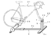
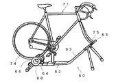
- FIG. 1 shows a bicycle trainer 10 according to a first embodiment.
- the body 3 of the bicycle trainer 10 includes a front-rear heel 3 a that extends horizontally in the front-rear direction, a rear leg 3 b that extends in the left-right direction at the rear portion of the front-rear heel 3 a, and a front-rear heel 3 a.
- a front leg 3c extending in the left-right direction is provided at the front portion.
- a rotating body 6 that rotates in contact with the outer periphery of the rear wheel 27 of the bicycle 21 is attached to the rear portion of the front / rear direction rod 3a.
- the rotating body 6 is composed of a roller member 6a having a predetermined outer diameter. It is supported by the main body 3 via a bracket (not shown).
- the support shaft 5 has a rod shape, and one end thereof is inserted into a hole (not shown) provided in a support shaft mounting base (not shown) fixed to the front-rear direction flange 3a, and the other end is fork end support means 7. It is fixed to.
- the bicycle 21 is mounted on the bicycle trainer 10 by attaching the fork end portion 23 of the bicycle 21 with the front wheel removed to the fork end support means 7.
- the outer peripheral surface is surrounded by the elastic portion 9, and the elastic portion 9 is elastic material such as natural rubber or synthetic rubber having elasticity. Consists of.
- the horizontal section of the elastic portion 9 is annular, its inner peripheral surface is in contact with the outer peripheral surface of the support shaft 5, and its outer surface is the inner surface of a short metal tube (about 2 to 3 cm, not shown). It touches.
- the metal tube is attached to the main body 3 by four fixing members 8a, 8b, 8c, and 8d fixed to the front portion of the front-rear flange 3a and the front leg 3c, respectively.
- the support shaft 5 is a stainless steel pipe.
- the bicycle training apparatus 10 performs training by attaching a bicycle 21 from which at least the front wheel is removed and applying a load to the pedal 28. Placed stably.
- the front wheel of the bicycle 21 is removed from the frame end portion 23 together with its axle (hub), and the frame end portion 23 is attached to the frame of the bicycle training device 10. It is supported by the end fixing means 7.
- the rear wheel 27 is placed on the roller member 6 a of the rotating body 6 provided at the rear portion of the training apparatus 10.
- This force is a force that pushes and bends the support shaft 5 forward.
- the upper portion of the support shaft 5 near the frame end fixing means 7) is placed in a frame (metal tube) whose periphery is fixed to the main body 3. Since it is surrounded by the provided elastic portion 9, the force for bending the support shaft 5 is limited.
- the support shaft 5 bends to a certain extent by the force thus limited, and the bicycle 21 tilts forward appropriately. Also, if the trainee applies a force and tilts the bicycle 21 to the left or right assuming that it turns left or right, the support shaft 5 is similarly bent to a certain degree by the left or right force, and the bicycle 21 is moderate. Lean left or right.
- the bicycle 21 when the trainee tries to move the bicycle 21 back and forth and left and right, the bicycle 21 also moves back and forth or tilts left and right as if actually training outdoors. It becomes possible to move.
- the swing angle is set to a maximum inclination angle when the bicycle 21 is actually driven straight ahead outdoors, for example, 5 degrees or less with respect to a line perpendicular to the floor on which the main body 3 is placed.
- the elastic modulus of the elastic material constituting the elastic portion 9 (longitudinal elastic modulus or Young's modulus), the size of the elastic portion 9, or the position of the support shaft 5 to which the elastic portion 9 is attached.
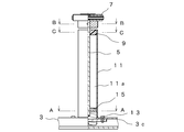
- FIG. 2 shows a bicycle trainer 20 according to the second embodiment.
- the bicycle trainer 20 is different from the first embodiment in that the frame portion 11 is erected at the front portion of the front-rear direction rod 3a.
- the frame part 11 has a cylindrical hollow part (not shown) inside, and the support shaft 5 is disposed therein.
- the upper end (the other end) of the support shaft 5 extends from the frame portion 11, and the fork end support means 7 is fixed to the other end.
- the fork end portion 23 of the bicycle 21 is attached to the fork end support means 7 by front fork claws (not shown).
- Other structures are the same as those of the bicycle trainer 10 of the first embodiment.
- FIG. 3 is a one-side longitudinal sectional view of the frame portion 11 and the fork end support means 7 according to the second embodiment as viewed from the front direction (the right side of the paper surface of FIG. 2).
- the frame part 11 has a cylindrical hollow part 11a inside, and a support shaft 5 is accommodated in the longitudinal direction at the center of the hollow part 11a.
- a lower portion of the frame portion 11 is inserted into a support bearing 15 fixed to the front leg 3c with bolts 13 and 13, and an upper portion thereof is covered with an elastic portion 9 having a predetermined thickness, and the center of the elastic portion 9 is supported by a support shaft.
- the upper end (the other end) of the support shaft 5 is fixed to the fork end support means 7.
- the lower portion of the support shaft 5 is inserted into a hole 15 a provided in the support bearing 15 in a state where the support shaft 5 can swing and move back and forth and right and left.
- the material of the support bearing 15 is aluminum
- the support shaft 5 is a cylindrical steel material made of stainless steel.
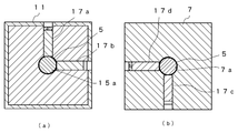
- FIG. 4A and 4B are cross-sectional views taken along lines AA and BB in FIG. 3, respectively.
- the frame portion 11 is inserted into the support bearing 15, and the support shaft 5 is inserted into a hole 15 a opened in the center of the support bearing 15.
- the position of the support shaft 5 can be adjusted by the tightening degree of the screws 17a and 17b.
- the lower portion of the fork end support means 7 has a quadrangular cross section, a hole 7a is provided at the center thereof, and the support shaft 5 is inserted into the hole 7a from its upper end.
- the position of the support shaft 5 can be adjusted by the tightening degree of the screws 17c and 17d.
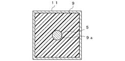
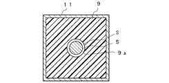
- FIG. 5 is a cross-sectional view taken along the line CC of FIG.
- the elastic part 9 is provided in the upper part of the frame part 11, the hole 9a is opened in the center of the elastic part 9, and the spindle 5 has penetrated this hole 9a.
- an elastomer elastomer
- the elastic portion 9 is provided in the upper portion of the hollow portion of the frame portion 11 and the support shaft 5 penetrates the center thereof. Can be limited to. The degree can be adjusted by selecting characteristics of the elastic material constituting the elastic portion 9 (for example, longitudinal elastic modulus or Young's modulus).
- Example 2- there may be a gap S between the elastic portion 9 and the support shaft 5 without the elastic portion 9 and the outer peripheral surface of the support shaft 5 being in contact with each other. With such a structure, the bending state of the support shaft 5 is adjusted by the elastic portion 9.
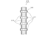
- FIG. 7 shows a part of the support shaft of the bicycle trainer according to the third embodiment.
- the support shaft 25 has a support shaft portion 35 having a rod-like structure in which elastic members 33 and connecting portions 31 made of a metal material are alternately arranged.
- the elastic member 33 is made of an elastic material such as elastic natural rubber or synthetic rubber, and the connecting portion 31 is made of a metal material such as stainless steel and is welded to the elastic member 33.
- the elastic member 33 when the support shaft 25 is attached to the main body (not shown) of the bicycle trainer, the elastic member 33 is configured from the main body side (one end) to the upper end (the other end) of the support shaft 25. The elastic modulus of the elastic material is successively decreased.
- the bicycle trainer according to the present invention is not limited to the above-described embodiment, and can take various configurations without departing from the gist of the present invention.
- the support shaft 5 may be an elastic member having elasticity such as a spring.
- the elastic portion 9 may be provided in the entire hollow portion of the frame portion 11.
- the bicycle trainer according to the present invention can be used outdoors in indoor training, which tends to be monotonous, because the bicycle moves back and forth and tilts left and right in response to the force of stepping on the pedal or the force of bending the bicycle left and right. It is useful as a training device that can train while obtaining the same feel as in running. Therefore, it is also suitable for a training apparatus for athletes who need endurance and strong strength training.
Landscapes
- Health & Medical Sciences (AREA)
- General Health & Medical Sciences (AREA)
- Physical Education & Sports Medicine (AREA)
- Life Sciences & Earth Sciences (AREA)
- Biophysics (AREA)
- Orthopedic Medicine & Surgery (AREA)
- Cardiology (AREA)
- Vascular Medicine (AREA)
- Motorcycle And Bicycle Frame (AREA)
- Rehabilitation Tools (AREA)
- Steering Devices For Bicycles And Motorcycles (AREA)
Abstract
La présente invention se rapporte à une bicyclette d'exercice qui fournit une sensation de conduite similaire à celle que l'on ressent sur une bicyclette en plein air. La bicyclette d'exercice sert à s'entraîner grâce à une bicyclette installée de manière amovible (21) et est pourvue des éléments suivants : un corps principal (3) placé sur le plancher ; un arbre de support (5) dans lequel une extrémité est insérée de manière amovible dans le corps principal et l'autre extrémité est fixée à un moyen de support d'extrémité de fourche (7) qui supporte une partie d'extrémité de fourche (23) de la bicyclette ; et une partie élastique disposée de manière à entourer au moins une partie de l'arbre de support à partir du centre dans le centre longitudinal de celui-ci vers l'autre extrémité. L'arbre de support se déforme élastiquement du fait de la force appliquée à partir de la partie d'extrémité de fourche et, par conséquent, la bicyclette peut se déplacer vers l'avant et vers l'arrière et s'incliner vers la gauche et la droite.
Priority Applications (2)
| Application Number | Priority Date | Filing Date | Title |
|---|---|---|---|
| EP13751538.3A EP2818214B1 (fr) | 2012-02-23 | 2013-02-21 | Bicyclette d'exercice |
| US14/380,676 US9486667B2 (en) | 2012-02-23 | 2013-02-21 | Bicycle trainer |
Applications Claiming Priority (2)
| Application Number | Priority Date | Filing Date | Title |
|---|---|---|---|
| JP2012037881A JP5876321B2 (ja) | 2012-02-23 | 2012-02-23 | 自転車用トレーナ |
| JP2012-037881 | 2012-02-23 |
Publications (1)
| Publication Number | Publication Date |
|---|---|
| WO2013125627A1 true WO2013125627A1 (fr) | 2013-08-29 |
Family
ID=49005805
Family Applications (1)
| Application Number | Title | Priority Date | Filing Date |
|---|---|---|---|
| PCT/JP2013/054308 WO2013125627A1 (fr) | 2012-02-23 | 2013-02-21 | Bicyclette d'exercice |
Country Status (4)
| Country | Link |
|---|---|
| US (1) | US9486667B2 (fr) |
| EP (1) | EP2818214B1 (fr) |
| JP (1) | JP5876321B2 (fr) |
| WO (1) | WO2013125627A1 (fr) |
Families Citing this family (12)
| Publication number | Priority date | Publication date | Assignee | Title |
|---|---|---|---|---|
| NZ718306A (en) * | 2013-09-27 | 2020-01-31 | Sbi Media Holding Sa | Bicycle trainer |
| NL2016178B1 (en) | 2016-01-28 | 2017-08-01 | Tacx Roerend En Onroerend Goed B V | Bicycle trainer. |
| JP6143248B1 (ja) * | 2017-01-31 | 2017-06-07 | 株式会社グロータック | 自転車トレーナーの傾斜調整装置 |
| JP6143247B1 (ja) * | 2017-01-31 | 2017-06-07 | 株式会社グロータック | 自転車トレーナーの傾斜調整装置 |
| US10493320B2 (en) * | 2017-07-19 | 2019-12-03 | Anant Porwal | Exercise assembly |
| US11992725B2 (en) | 2017-08-17 | 2024-05-28 | Saris Equipment, Llc | Movably supported exercise device |
| US10384111B2 (en) * | 2017-11-08 | 2019-08-20 | Shu-Chiung Liao Lai | Bicycle trainer |
| NL2020892B1 (en) | 2018-05-08 | 2019-11-14 | Tacx Roerend En Onroerend Goed B V | Power measurement device |
| DE202019103536U1 (de) * | 2019-06-26 | 2019-09-03 | Mathias Seidler | Vorrichtung zum Aufsitzen für eine Person zu Trainingszwecken zum Ausüben einer dem Radfahren ähnlichen Beinrotationsbewegung |
| BR102020003322A2 (pt) * | 2020-02-17 | 2021-08-31 | Aruanã Energia S/A | Estande para bicicleta em ambiente interno com graus de movimento lateral |
| US12053667B2 (en) | 2020-05-20 | 2024-08-06 | Saris Equipment, Llc | Lean based steering system for use with tilting cycle |
| US11970233B1 (en) | 2023-06-21 | 2024-04-30 | Brian S Wirtz | Bicycle fork mounting device |
Citations (6)
| Publication number | Priority date | Publication date | Assignee | Title |
|---|---|---|---|---|
| JPH0257947A (ja) | 1988-08-23 | 1990-02-27 | Shimadzu Corp | Atr分光分析用試料セル |
| JPH0257947B2 (fr) * | 1987-03-18 | 1990-12-06 | Osamu Nagaoka | |
| JP3046083U (ja) * | 1997-08-08 | 1998-02-20 | 晟堅企業股▲ふん▼有限公司 | 単輪車によるバランス運動の練習装置 |
| US6126577A (en) * | 1998-09-04 | 2000-10-03 | Chang; Jeffery | Exercise stationary bicycle |
| JP2002062426A (ja) | 2000-08-15 | 2002-02-28 | Fuji Photo Film Co Ltd | 配向膜、光学補償シート、楕円偏光板、およびそれを用いた液晶表示装置 |
| WO2002062426A1 (fr) * | 2001-02-06 | 2002-08-15 | Mizuno Corporation | Appareil d'entrainement pour bicyclette |
Family Cites Families (7)
| Publication number | Priority date | Publication date | Assignee | Title |
|---|---|---|---|---|
| US1139732A (en) * | 1914-02-28 | 1915-05-18 | Edwin E Slick | Spring. |
| US2551505A (en) * | 1946-12-04 | 1951-05-01 | Jr Raymond G Olson | Cushioning device |
| US4494662A (en) * | 1983-03-04 | 1985-01-22 | Clymer Ronald S | Mounted spring device for resisting flexing |
| US6056672A (en) * | 1996-08-20 | 2000-05-02 | Carbonell Tendero; D. Juan Jose | Training apparatus for cyclist and for physical exercise |
| US5816818A (en) * | 1997-08-11 | 1998-10-06 | Shen Chien Enterprise Co., Ltd. | Training device for riding a unicycle |
| WO2007083341A1 (fr) * | 2006-01-17 | 2007-07-26 | M.C. Meccanica Cesanense Di Paialunga Loriana | Simulateur routier pour bicyclette |
| US8419597B2 (en) * | 2009-08-17 | 2013-04-16 | Emily L. Cooper | Systems and methods for a hill training apparatus for a bicycle trainer |
-
2012
- 2012-02-23 JP JP2012037881A patent/JP5876321B2/ja active Active
-
2013
- 2013-02-21 WO PCT/JP2013/054308 patent/WO2013125627A1/fr active Application Filing
- 2013-02-21 US US14/380,676 patent/US9486667B2/en active Active
- 2013-02-21 EP EP13751538.3A patent/EP2818214B1/fr not_active Not-in-force
Patent Citations (6)
| Publication number | Priority date | Publication date | Assignee | Title |
|---|---|---|---|---|
| JPH0257947B2 (fr) * | 1987-03-18 | 1990-12-06 | Osamu Nagaoka | |
| JPH0257947A (ja) | 1988-08-23 | 1990-02-27 | Shimadzu Corp | Atr分光分析用試料セル |
| JP3046083U (ja) * | 1997-08-08 | 1998-02-20 | 晟堅企業股▲ふん▼有限公司 | 単輪車によるバランス運動の練習装置 |
| US6126577A (en) * | 1998-09-04 | 2000-10-03 | Chang; Jeffery | Exercise stationary bicycle |
| JP2002062426A (ja) | 2000-08-15 | 2002-02-28 | Fuji Photo Film Co Ltd | 配向膜、光学補償シート、楕円偏光板、およびそれを用いた液晶表示装置 |
| WO2002062426A1 (fr) * | 2001-02-06 | 2002-08-15 | Mizuno Corporation | Appareil d'entrainement pour bicyclette |
Non-Patent Citations (1)
| Title |
|---|
| See also references of EP2818214A4 |
Also Published As
| Publication number | Publication date |
|---|---|
| US9486667B2 (en) | 2016-11-08 |
| EP2818214A4 (fr) | 2015-09-30 |
| EP2818214A1 (fr) | 2014-12-31 |
| US20150011364A1 (en) | 2015-01-08 |
| JP2013172775A (ja) | 2013-09-05 |
| JP5876321B2 (ja) | 2016-03-02 |
| EP2818214B1 (fr) | 2018-11-07 |
Similar Documents
| Publication | Publication Date | Title |
|---|---|---|
| JP5876321B2 (ja) | 自転車用トレーナ | |
| US9669257B2 (en) | Bicycling exercise apparatus | |
| US10398934B2 (en) | Bicycling exercise apparatus | |
| US7670230B2 (en) | Transmission mechanism for balance training apparatus | |
| KR20170033780A (ko) | 자전거 시뮬레이터 | |
| US11235199B2 (en) | Bicycling exercise apparatus | |
| JP2021126520A (ja) | 横方向に移動可能な室内用自転車スタンド | |
| JP2007330732A (ja) | 自転車型トレーニング装置 | |
| KR101900344B1 (ko) | 탱크 바이크 시뮬레이션 장치 | |
| KR101915639B1 (ko) | 가상 현실을 이용한 자전거 운동 기구 | |
| KR101635514B1 (ko) | 자전거 시뮬레이터 | |
| KR101267963B1 (ko) | 커빙 시뮬레이션 장치 | |
| CN103961842A (zh) | 运动用自行车支撑台 | |
| CN108001569B (zh) | 一种翘板式自行车辅助学习器 | |
| JP3127734U6 (ja) | エクササイズバイク | |
| KR101705452B1 (ko) | 케이블 마운팅장치 | |
| JP3127734U (ja) | エクササイズバイク |
Legal Events
| Date | Code | Title | Description |
|---|---|---|---|
| 121 | Ep: the epo has been informed by wipo that ep was designated in this application |
Ref document number: 13751538 Country of ref document: EP Kind code of ref document: A1 |
|
| WWE | Wipo information: entry into national phase |
Ref document number: 14380676 Country of ref document: US |
|
| NENP | Non-entry into the national phase |
Ref country code: DE |
|
| WWE | Wipo information: entry into national phase |
Ref document number: 2013751538 Country of ref document: EP |