WO2013121946A1 - 自動二輪車用空気入りタイヤ - Google Patents
自動二輪車用空気入りタイヤ Download PDFInfo
- Publication number
- WO2013121946A1 WO2013121946A1 PCT/JP2013/052689 JP2013052689W WO2013121946A1 WO 2013121946 A1 WO2013121946 A1 WO 2013121946A1 JP 2013052689 W JP2013052689 W JP 2013052689W WO 2013121946 A1 WO2013121946 A1 WO 2013121946A1
- Authority
- WO
- WIPO (PCT)
- Prior art keywords
- groove
- tire
- rotation direction
- connecting portion
- curvature
- Prior art date
- Legal status (The legal status is an assumption and is not a legal conclusion. Google has not performed a legal analysis and makes no representation as to the accuracy of the status listed.)
- Ceased
Links
Images

Classifications
-
- B—PERFORMING OPERATIONS; TRANSPORTING
- B60—VEHICLES IN GENERAL
- B60C—VEHICLE TYRES; TYRE INFLATION; TYRE CHANGING; CONNECTING VALVES TO INFLATABLE ELASTIC BODIES IN GENERAL; DEVICES OR ARRANGEMENTS RELATED TO TYRES
- B60C11/00—Tyre tread bands; Tread patterns; Anti-skid inserts
- B60C11/03—Tread patterns
- B60C11/0327—Tread patterns characterised by special properties of the tread pattern
-
- B—PERFORMING OPERATIONS; TRANSPORTING
- B60—VEHICLES IN GENERAL
- B60C—VEHICLE TYRES; TYRE INFLATION; TYRE CHANGING; CONNECTING VALVES TO INFLATABLE ELASTIC BODIES IN GENERAL; DEVICES OR ARRANGEMENTS RELATED TO TYRES
- B60C11/00—Tyre tread bands; Tread patterns; Anti-skid inserts
- B60C11/03—Tread patterns
- B60C11/032—Patterns comprising isolated recesses
-
- B—PERFORMING OPERATIONS; TRANSPORTING
- B60—VEHICLES IN GENERAL
- B60C—VEHICLE TYRES; TYRE INFLATION; TYRE CHANGING; CONNECTING VALVES TO INFLATABLE ELASTIC BODIES IN GENERAL; DEVICES OR ARRANGEMENTS RELATED TO TYRES
- B60C11/00—Tyre tread bands; Tread patterns; Anti-skid inserts
- B60C11/03—Tread patterns
- B60C11/0302—Tread patterns directional pattern, i.e. with main rolling direction
-
- B—PERFORMING OPERATIONS; TRANSPORTING
- B60—VEHICLES IN GENERAL
- B60C—VEHICLE TYRES; TYRE INFLATION; TYRE CHANGING; CONNECTING VALVES TO INFLATABLE ELASTIC BODIES IN GENERAL; DEVICES OR ARRANGEMENTS RELATED TO TYRES
- B60C11/00—Tyre tread bands; Tread patterns; Anti-skid inserts
- B60C11/03—Tread patterns
- B60C11/0304—Asymmetric patterns
-
- B—PERFORMING OPERATIONS; TRANSPORTING
- B60—VEHICLES IN GENERAL
- B60C—VEHICLE TYRES; TYRE INFLATION; TYRE CHANGING; CONNECTING VALVES TO INFLATABLE ELASTIC BODIES IN GENERAL; DEVICES OR ARRANGEMENTS RELATED TO TYRES
- B60C11/00—Tyre tread bands; Tread patterns; Anti-skid inserts
- B60C11/03—Tread patterns
- B60C2011/0337—Tread patterns characterised by particular design features of the pattern
- B60C2011/0339—Grooves
- B60C2011/0381—Blind or isolated grooves
-
- B—PERFORMING OPERATIONS; TRANSPORTING
- B60—VEHICLES IN GENERAL
- B60C—VEHICLE TYRES; TYRE INFLATION; TYRE CHANGING; CONNECTING VALVES TO INFLATABLE ELASTIC BODIES IN GENERAL; DEVICES OR ARRANGEMENTS RELATED TO TYRES
- B60C2200/00—Tyres specially adapted for particular applications
- B60C2200/10—Tyres specially adapted for particular applications for motorcycles, scooters or the like
Definitions
- the present invention relates to a pneumatic tire for a motorcycle (hereinafter, also simply referred to as “tire”), and more particularly, to a pneumatic tire for a motorcycle according to an improvement in an arrangement condition of grooves formed on a surface of a tread portion.
- the front tire of a motorcycle has a role as a steering wheel that controls the vehicle body according to steering of the steering wheel. Therefore, in order for the rider to run stably and comfortably, the front tire has a handle according to the rider's intention. It is necessary to have a flexible characteristic that can be operated easily.
- a pneumatic tire for motorcycles has a characteristic that the vehicle body is first tilted by turning the steering wheel, and after adding a camber angle (CA), it turns with a balance that matches the turning force of the tire. Therefore, in order to smoothly advance the turning action in the front tire for a motorcycle, it is necessary to set the steering wheel steering to be moderately and easily cut by appropriately reducing the pattern rigidity in the vicinity of the tire center. Therefore, for the front tire, a technique has been employed in which the rigidity of the tread is lowered by appropriately reducing the pattern rigidity, for example, by arranging a circumferential groove in the center portion.
- CA camber angle
- Patent Document 1 As a technique related to improvement of a tread pattern of a pneumatic tire for a motorcycle, for example, there is a technique disclosed in Patent Document 1.
- the technique disclosed in Patent Document 1 aims to achieve both wet drainage and straight handling.
- an object of the present invention is to provide a technique for improving the lightness of a motorcycle front tire without impairing other performance such as wear performance, based on the characteristics of the motorcycle tire described above.
- the object is to provide a pneumatic tire for a motorcycle that has both stability and stability.
- the inventor has found that the above problem can be solved by arranging the main groove branched in the tire tread and prescribing the shape of the branched portion to a predetermined value, and has completed the present invention. It was.
- the present invention is a pneumatic tire for a motorcycle having a tread portion, a sidewall portion and a bead portion that are continuous on both sides of the tread portion, and a rotation direction when the vehicle is mounted is specified.
- a first groove extending incline toward one side of the tire width direction toward the designated tire rotation direction, and a reverse rotation direction end of the first groove in the designated tire rotation direction, the designated tire
- a second groove extending in the direction of rotation toward the other side in the tire width direction and the end of the first tire and the second groove in the reverse rotation direction of the designated tire rotation direction
- a third main groove extending in the reverse rotation direction of the first main groove and a branched main groove, and a connecting portion between the first groove and the second groove is formed in a curved shape.
- the second groove and the second groove are configured by a curve having a center of curvature radius on the reverse rotation direction side of the designated tire rotation direction, and the third groove has a curvature radius on the tire center portion side. It is characterized by comprising a curve having a center.
- the center of the branch portion of the main groove is separated from the tire central portion in the tire width direction.
- the connecting portion between the first groove and the third groove, and the connecting portion between the third groove and the second groove are formed in a curved shape. Preferably it is.
- the radius of curvature of the connecting portion between the first groove and the second groove is R A
- the radius of curvature of the connecting portion between the first groove and the third groove is R B
- the radius of curvature of the connecting portion between the groove and the second groove of the third when the R C it is preferable to satisfy the relationship of R a> R B and R a> R C.
- the radius of curvature R A of the connecting portion between the first groove and the second groove is in the range of 12 to 18 mm
- the first groove and the third groove in the range of the curvature radius R B is 4 ⁇ 8 mm of the connecting portion between
- the radius of curvature R C of the connecting portion between the groove and the second groove of the third is in the range of 6 ⁇ 10 mm.
- 1 is a partial development view showing a tread of an example of a pneumatic tire for a motorcycle according to the present invention.
- 1 is a schematic cross-sectional view showing an example of a pneumatic tire for a motorcycle according to the present invention.
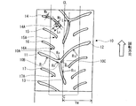
- FIG. 1 is a partial development view showing a tread of an example of a pneumatic tire for a motorcycle according to the present invention.
- FIG. 2 is a schematic sectional view showing an example of a pneumatic tire for motorcycles according to the present invention.
- the pneumatic tire for a motorcycle of the present invention has a tread portion 1, sidewall portions 2 and bead portions 3 connected to both sides thereof, and a rotation direction when the vehicle is mounted is designated. A so-called directional pattern.
- the arrow in FIG. 1 shows the rotation direction (designated rotation direction) at the time of vehicle mounting.
- the tire tread is provided with a branched main groove 10 composed of first to third grooves.
- the main groove 10 includes a first groove 11 extending in a slanting direction toward the designated tire rotation direction and one side in the tire width direction, and a designated tire from a reverse rotation direction end of the designated groove rotation direction of the first groove 11.
- a designated tire rotation direction from a second groove 12 extending toward the other direction in the tire width direction toward the rotation direction and extending in the opposite direction of the designated tire rotation direction of the first groove 11 and the second groove 12
- a third groove 13 extending in the reverse rotation direction.
- it is important that the connecting portion 10A between the first groove 11 and the second groove 12 is formed in a curved shape.
- the torsional rigidity of the tread surface is lowered without impairing the lateral rigidity necessary for the turning force, and the lightness that has conventionally been a contradiction, It has become possible to realize a pneumatic tire for a motorcycle that achieves both good turning performance and wear performance and has both economic efficiency and stability.
- the discontinuity of rigidity in the connecting portion 10A is formed by forming the connecting portion 10A between the first groove 11 and the second groove 12 connected at least approximately in the tire width direction in a curved shape. Since it can be eliminated, it is possible to obtain the effect of improving the handling characteristics at the time of slalom running, which is particularly required for a touring tire.
- the first groove 11 and the third groove in addition to the connecting portion 10A between the first groove 11 and the second groove 12 as shown in the figure.
- the connecting portion 10B with the groove 13 and the connecting portion 10C with the third groove 13 and the second groove 12 are also preferably formed in a curved shape. This is because the rigidity continuity at the branch portion of the main groove 10 can be further increased.
- the radius of curvature of the connecting portion 10A between the first groove 11 and the second groove 12 is R A
- the radius of curvature of the connecting portion 10B between the first groove 11 and the third groove 13 is R B
- the curvature radius of each of the connecting portions has a relationship of R A > R B and R A > RC . It is preferable to satisfy.
- the first groove 11 and the second groove 12 are configured by curves having centers of the curvature radii R 11 and R 12 on the reverse rotation direction side of the designated tire rotation direction, and the third groove 13 is required to be composed by a curve having a center of curvature radius R 13 on the tire center side.
- the rear tire functions as a driving wheel
- the front tire functions as a steering wheel
- the inputs to the front tire are braking force and lateral force. Therefore, in order to effectively exert the turning force, it is necessary to dispose the groove in a direction that does not hinder the input as much as possible, that is, in a direction along the input.
- the first groove 11 and the second groove 12 are configured by curves having a center of curvature radius on the reverse rotation direction side of the designated tire rotation direction, that is, on the rear side with respect to the traveling direction.
- the third groove 13 extending substantially in the tire circumferential direction, it is effective for improving the turning force to lower the bending rigidity of the center portion and improve the ground contact. Therefore, the third groove 13 is configured by a curve having the center of the radius of curvature at the tire central portion side, and the bending rigidity of the second groove 12 and the connecting portion 10C of the third groove 13 is reduced, thereby reducing the ground contact. Improve sexiness.
- channel 13 inclines with respect to a tire circumferential direction so that it may show in figure, and the edge part of the reverse rotation direction of the designated tire rotation direction has extended beyond the tire center part. Is preferred. Thereby, the effect of reducing the torsional rigidity of the tire central portion can be obtained.
- the center of the branch portion of the main groove 10 is preferably spaced from the tire center portion CL in the tire width direction, and the separation length L from the tire center portion CL to the center of the branch portion is preferred.
- Preferably satisfies the range of 0.05 ⁇ L / TW ⁇ 0.25 when the tread half width is TW.
- the branch portion of the main groove 10 is in a position that satisfies the above range.
- L / TW exceeds 0.25, the effect of improving lightness due to a decrease in pattern rigidity is reduced, and when L / TW is less than 0.05, the initial turning force is significantly reduced. Note that the wear performance is hardly affected by the degree of arrangement of the branched main groove 10.
- the length of each groove is a length measured along the groove.
- lug grooves 14 to 17 whose inner end portion in the tire width direction terminates in one side region of the tread portion are arranged.
- Lug grooves 14 to 17 having inner end portions in the tire width direction at the inner ends thereof have widened portions having groove widths w B larger than the groove width w A at portions other than the inner end portions in the tire width direction at the inner end portions in the tire width direction.
- it has 14A to 17A.
- the widening ratios w B / w A of the widened portions 11A to 14A preferably satisfy the relationship represented by 1.1 ⁇ w B / w A ⁇ 3.
- the pattern rigidity can be effectively reduced only in the vicinity of the widened portion.
- a light resistance was in contradiction trend swirling force and wear performance and better to both economy and stability It is possible to realize a pneumatic tire for a motorcycle that has both characteristics.
- the widening ratio w B / w A of the widened portion exceeds 3, the reduction of the turning force due to the decrease in pattern rigidity becomes significant. On the other hand, when it is less than 1.1, the effect of improving the lightness becomes insufficient. . Note that the wear performance is hardly affected by the widening of the lug groove tip only.
- the widening ratio w B / w A preferably satisfies the relationship represented by 1.3 ⁇ w B / w A ⁇ 2.5.
- the tire tread peripheral length means that the tire is assembled on a rim specified by an industrial standard effective in the region where the tire is produced and used, and is filled with the internal pressure specified by the industrial standard.
- the length measured from the one tread end to the other tread end in the tire width direction along the tread surface.
- the above-mentioned industry standards are JATMA (Japan Automobile Tire Association) YEAR BOOK in Japan, ETRTO (European Tire and Rim Technical Organization) STANDARD MANUAL, etc. .
- the groove width w A of the lug groove other than the tire width direction inner end and the groove width w B of the tire width direction inner end are orthogonal to the direction along the lug groove. It means the groove width measured in the direction.
- the widened portion only needs to be provided in the tire width direction inner end portion of the lug groove, that is, in the tire central region C, and the length of the widened portion in the direction along the lug groove.
- the length of the widened portion in the direction along the lug groove is too long, the pattern rigidity may be lowered too much.On the other hand, if the length is too short, the effect of improving lightness may not be sufficient.
- the length L B of the widened portion along the lug groove satisfies 0.5 ⁇ L B / w B ⁇ 3. Furthermore, in the example shown in the figure, the widened portion is provided in a form that widens the groove width on the reverse rotation direction side of the designated tire rotation direction, but may be provided in a form that widens the groove width on the designated tire rotation direction side, Alternatively, the groove width may be increased on both sides.
- the widened portion is provided at the inner end portion in the tire width direction of the lug groove having the inner end portion in the tire width direction in the tire central region C.
- widening portions are provided in all of the plurality of lug grooves arranged in the tire tread.
- the plurality of lug grooves all have inner ends in the tire width direction in the central region C.
- the arrangement conditions of the plurality of lug grooves are not particularly limited. However, as shown in the drawing, they are alternately arranged left and right asymmetrically at a ratio of 3: 1 between both side regions of the tread portion. It is preferable to do. By arranging the lug grooves asymmetrically and alternately while adjusting the ratio between the two side regions, it is possible to satisfactorily balance the stiffness between the two side regions of the tread portion.
- the arrangement pitch of the main grooves, particularly the main grooves and the lug grooves in the present invention is not particularly limited, but can be, for example, about 1/8 to 1/10 of the entire circumference of the tire.
- the tire of the present invention includes a carcass 5 that is disposed between bead cores 4 embedded in a pair of bead portions 3 and reinforces each portion, and a belt 6 that is disposed on the outer periphery and reinforces the tread portion 1. And have.
- the belt 6 may be composed of two or more inclined belt layers arranged such that the cord directions intersect each other between the layers, and one or more layers in which the cord direction is substantially the tire circumferential direction.
- the spiral belt layer may be used.
- the present invention is useful as a front tire for a motorcycle, and can be applied to any tire having a radial structure and a bias structure.
- Each of the obtained test tires was attached to a large motorcycle with a displacement of 1000 cc, and the lightness, turning force and handling were evaluated by feeling evaluation by an actual vehicle test.
- a commercially available tire size MCR180 / 55ZR17M / C was used as the rear tire.
- the results are indicated by an index with a normal level of 100 points for each performance. The larger the item, the higher the performance and the better.
- permissible_range equivalent level
- the tires of the examples in which the predetermined branched main grooves including the first to third grooves are arranged on the tire tread have improved lightness without impairing the turning force and handling performance. It has been confirmed that.
Landscapes
- Engineering & Computer Science (AREA)
- Mechanical Engineering (AREA)
- Tires In General (AREA)
Priority Applications (2)
| Application Number | Priority Date | Filing Date | Title |
|---|---|---|---|
| EP13749219.5A EP2815897B1 (en) | 2012-02-13 | 2013-02-06 | Pneumatic motorcycle tire |
| US14/377,921 US9731559B2 (en) | 2012-02-13 | 2013-02-06 | Pneumatic motorcycle tire |
Applications Claiming Priority (2)
| Application Number | Priority Date | Filing Date | Title |
|---|---|---|---|
| JP2012-028549 | 2012-02-13 | ||
| JP2012028549A JP5497813B2 (ja) | 2012-02-13 | 2012-02-13 | 自動二輪車用空気入りタイヤ |
Publications (1)
| Publication Number | Publication Date |
|---|---|
| WO2013121946A1 true WO2013121946A1 (ja) | 2013-08-22 |
Family
ID=48921073
Family Applications (1)
| Application Number | Title | Priority Date | Filing Date |
|---|---|---|---|
| PCT/JP2013/052689 Ceased WO2013121946A1 (ja) | 2012-02-13 | 2013-02-06 | 自動二輪車用空気入りタイヤ |
Country Status (5)
| Country | Link |
|---|---|
| US (1) | US9731559B2 (enExample) |
| EP (1) | EP2815897B1 (enExample) |
| JP (1) | JP5497813B2 (enExample) |
| CN (2) | CN203157612U (enExample) |
| WO (1) | WO2013121946A1 (enExample) |
Cited By (1)
| Publication number | Priority date | Publication date | Assignee | Title |
|---|---|---|---|---|
| JP2013193518A (ja) * | 2012-03-16 | 2013-09-30 | Sumitomo Rubber Ind Ltd | 自動二輪車用タイヤ |
Families Citing this family (4)
| Publication number | Priority date | Publication date | Assignee | Title |
|---|---|---|---|---|
| JP5497813B2 (ja) | 2012-02-13 | 2014-05-21 | 株式会社ブリヂストン | 自動二輪車用空気入りタイヤ |
| CN107657130A (zh) * | 2017-10-18 | 2018-02-02 | 安徽佳通乘用子午线轮胎有限公司 | 一种面向轮胎花纹结构设计参数的逆向建模方法 |
| CN108146436B (zh) * | 2017-12-26 | 2023-10-27 | 北京汽车研究总院有限公司 | 一种控制车辆行驶的方法及车辆 |
| TWI771029B (zh) * | 2021-05-31 | 2022-07-11 | 正新橡膠工業股份有限公司 | 提高操縱穩定性能之輪胎 |
Citations (4)
| Publication number | Priority date | Publication date | Assignee | Title |
|---|---|---|---|---|
| JPH03135802A (ja) * | 1989-10-21 | 1991-06-10 | Sumitomo Rubber Ind Ltd | 二輪車用空気入りタイヤ |
| JP2001039120A (ja) | 1999-07-29 | 2001-02-13 | Bridgestone Corp | 二輪車用空気入りタイヤ |
| WO2006123480A1 (ja) * | 2005-05-17 | 2006-11-23 | Bridgestone Corporation | 自動二輪車用空気入りラジアルタイヤ |
| JP2007045239A (ja) * | 2005-08-08 | 2007-02-22 | Sumitomo Rubber Ind Ltd | 空気入りタイヤ、その製造方法及びそれに用いるタイヤ加硫金型 |
Family Cites Families (12)
| Publication number | Priority date | Publication date | Assignee | Title |
|---|---|---|---|---|
| US4364426A (en) | 1981-03-26 | 1982-12-21 | Dunlop Tire & Rubber Corporation | Motorcycle tire tread |
| ES2221121T3 (es) | 1997-02-27 | 2004-12-16 | Bridgestone Corporation | Cubierta neumatica para vehiculo de dos ruedas. |
| JP3676534B2 (ja) | 1997-04-10 | 2005-07-27 | 株式会社ブリヂストン | 空気入りタイヤ |
| JP2001030719A (ja) | 1999-07-23 | 2001-02-06 | Bridgestone Corp | 空気入りタイヤ |
| USD554045S1 (en) * | 2006-01-24 | 2007-10-30 | The Goodyear Tire & Rubber Company | Tire for motorcycle |
| TWD117491S1 (zh) * | 2006-05-10 | 2007-06-11 | 住友橡膠工業股份有限公司 | 自動二輪車用輪胎 |
| JP5475420B2 (ja) * | 2009-12-04 | 2014-04-16 | 株式会社ブリヂストン | 自動二輪車用空気入りタイヤ |
| CN102858559A (zh) | 2010-03-26 | 2013-01-02 | 株式会社普利司通 | 机动两轮车用充气轮胎 |
| CN103717411B (zh) | 2011-07-06 | 2019-04-02 | 倍耐力轮胎股份公司 | 摩托车轮胎 |
| JP5497813B2 (ja) | 2012-02-13 | 2014-05-21 | 株式会社ブリヂストン | 自動二輪車用空気入りタイヤ |
| JP5462901B2 (ja) * | 2012-03-16 | 2014-04-02 | 住友ゴム工業株式会社 | 自動二輪車用タイヤ |
| JP5945207B2 (ja) * | 2012-10-10 | 2016-07-05 | 株式会社ブリヂストン | 自動二輪車用タイヤ |
-
2012
- 2012-02-13 JP JP2012028549A patent/JP5497813B2/ja not_active Expired - Fee Related
-
2013
- 2013-02-06 US US14/377,921 patent/US9731559B2/en not_active Expired - Fee Related
- 2013-02-06 WO PCT/JP2013/052689 patent/WO2013121946A1/ja not_active Ceased
- 2013-02-06 EP EP13749219.5A patent/EP2815897B1/en active Active
- 2013-02-07 CN CN201320071847XU patent/CN203157612U/zh not_active Expired - Lifetime
- 2013-02-07 CN CN201310049879.4A patent/CN103241071B/zh not_active Expired - Fee Related
Patent Citations (4)
| Publication number | Priority date | Publication date | Assignee | Title |
|---|---|---|---|---|
| JPH03135802A (ja) * | 1989-10-21 | 1991-06-10 | Sumitomo Rubber Ind Ltd | 二輪車用空気入りタイヤ |
| JP2001039120A (ja) | 1999-07-29 | 2001-02-13 | Bridgestone Corp | 二輪車用空気入りタイヤ |
| WO2006123480A1 (ja) * | 2005-05-17 | 2006-11-23 | Bridgestone Corporation | 自動二輪車用空気入りラジアルタイヤ |
| JP2007045239A (ja) * | 2005-08-08 | 2007-02-22 | Sumitomo Rubber Ind Ltd | 空気入りタイヤ、その製造方法及びそれに用いるタイヤ加硫金型 |
Non-Patent Citations (1)
| Title |
|---|
| See also references of EP2815897A4 |
Cited By (1)
| Publication number | Priority date | Publication date | Assignee | Title |
|---|---|---|---|---|
| JP2013193518A (ja) * | 2012-03-16 | 2013-09-30 | Sumitomo Rubber Ind Ltd | 自動二輪車用タイヤ |
Also Published As
| Publication number | Publication date |
|---|---|
| CN103241071B (zh) | 2016-05-18 |
| JP2013163489A (ja) | 2013-08-22 |
| US20150041033A1 (en) | 2015-02-12 |
| CN203157612U (zh) | 2013-08-28 |
| JP5497813B2 (ja) | 2014-05-21 |
| EP2815897A1 (en) | 2014-12-24 |
| US9731559B2 (en) | 2017-08-15 |
| CN103241071A (zh) | 2013-08-14 |
| EP2815897B1 (en) | 2019-04-03 |
| EP2815897A4 (en) | 2015-11-25 |
Similar Documents
| Publication | Publication Date | Title |
|---|---|---|
| JP4234762B1 (ja) | 自動二輪車用タイヤとその製造方法 | |
| WO2021060033A1 (ja) | 自動二輪車用タイヤ | |
| JP5344064B2 (ja) | 空気入りタイヤ | |
| JP6502689B2 (ja) | 自動二輪車用空気入りタイヤ | |
| JP5291320B2 (ja) | 自動二輪車用空気入りタイヤ | |
| JP2012162160A (ja) | 自動二輪車用空気入りタイヤ | |
| JP5497813B2 (ja) | 自動二輪車用空気入りタイヤ | |
| JP5517319B1 (ja) | 自動二輪車用タイヤ | |
| JP4649215B2 (ja) | 自動二輪車用空気入りタイヤ | |
| JP5965138B2 (ja) | 自動二輪車用空気入りタイヤ | |
| JP4634841B2 (ja) | 二輪車用空気入りタイヤ | |
| JP5890192B2 (ja) | 自動二輪車用空気入りタイヤ | |
| WO2014024499A1 (ja) | 自動二輪車用空気入りタイヤ | |
| JP5945207B2 (ja) | 自動二輪車用タイヤ | |
| JP6053550B2 (ja) | 空気入りタイヤ | |
| JP6506061B2 (ja) | 自動二輪車用タイヤ | |
| JP4118391B2 (ja) | 二輪車用空気入りラジアルタイヤ | |
| WO2016047213A1 (ja) | 自動二輪車用タイヤ | |
| JP6581371B2 (ja) | 自動二輪車用タイヤ | |
| JP6060217B2 (ja) | 自動二輪車用空気入りタイヤ | |
| WO2015015701A1 (ja) | 自動二輪車用タイヤ | |
| JP5992177B2 (ja) | 自動二輪車用空気入りタイヤ | |
| JP4118392B2 (ja) | 二輪車用空気入りラジアルタイヤ | |
| JP2009061920A (ja) | 自動二輪車用タイヤとその製造方法 | |
| JP6506060B2 (ja) | 自動二輪車用タイヤ |
Legal Events
| Date | Code | Title | Description |
|---|---|---|---|
| 121 | Ep: the epo has been informed by wipo that ep was designated in this application |
Ref document number: 13749219 Country of ref document: EP Kind code of ref document: A1 |
|
| WWE | Wipo information: entry into national phase |
Ref document number: 14377921 Country of ref document: US |
|
| NENP | Non-entry into the national phase |
Ref country code: DE |
|
| WWE | Wipo information: entry into national phase |
Ref document number: 2013749219 Country of ref document: EP |