WO2013118702A1 - 有機化合物含有排水の処理方法 - Google Patents
有機化合物含有排水の処理方法 Download PDFInfo
- Publication number
- WO2013118702A1 WO2013118702A1 PCT/JP2013/052567 JP2013052567W WO2013118702A1 WO 2013118702 A1 WO2013118702 A1 WO 2013118702A1 JP 2013052567 W JP2013052567 W JP 2013052567W WO 2013118702 A1 WO2013118702 A1 WO 2013118702A1
- Authority
- WO
- WIPO (PCT)
- Prior art keywords
- oxidation catalyst
- organic compound
- catalyst reaction
- hydrogen peroxide
- reaction tower
- Prior art date
- Legal status (The legal status is an assumption and is not a legal conclusion. Google has not performed a legal analysis and makes no representation as to the accuracy of the status listed.)
- Ceased
Links
Images
Classifications
-
- C—CHEMISTRY; METALLURGY
- C02—TREATMENT OF WATER, WASTE WATER, SEWAGE, OR SLUDGE
- C02F—TREATMENT OF WATER, WASTE WATER, SEWAGE, OR SLUDGE
- C02F1/00—Treatment of water, waste water, or sewage
- C02F1/72—Treatment of water, waste water, or sewage by oxidation
- C02F1/725—Treatment of water, waste water, or sewage by oxidation by catalytic oxidation
-
- C—CHEMISTRY; METALLURGY
- C02—TREATMENT OF WATER, WASTE WATER, SEWAGE, OR SLUDGE
- C02F—TREATMENT OF WATER, WASTE WATER, SEWAGE, OR SLUDGE
- C02F1/00—Treatment of water, waste water, or sewage
- C02F1/72—Treatment of water, waste water, or sewage by oxidation
- C02F1/722—Oxidation by peroxides
-
- C—CHEMISTRY; METALLURGY
- C02—TREATMENT OF WATER, WASTE WATER, SEWAGE, OR SLUDGE
- C02F—TREATMENT OF WATER, WASTE WATER, SEWAGE, OR SLUDGE
- C02F2101/00—Nature of the contaminant
- C02F2101/30—Organic compounds
- C02F2101/34—Organic compounds containing oxygen
-
- C—CHEMISTRY; METALLURGY
- C02—TREATMENT OF WATER, WASTE WATER, SEWAGE, OR SLUDGE
- C02F—TREATMENT OF WATER, WASTE WATER, SEWAGE, OR SLUDGE
- C02F2209/00—Controlling or monitoring parameters in water treatment
- C02F2209/20—Total organic carbon [TOC]
Definitions
- the present invention relates to a method for treating organic compound-containing wastewater, and in particular, treatment of organic compound-containing wastewater that can be efficiently decomposed in the presence of a catalyst using hydrogen peroxide as an oxidizing agent. Regarding the method.
- Patent Document 1 discloses that hydrogen peroxide is added to imidazolidinone-based compound-containing wastewater and the porous carrier is heated at 100 to 180 ° C. under heating conditions.
- a wastewater treatment method in which wastewater is brought into contact with a catalyst by oxidative decomposition of an imidazolidinone compound by passing it through a reaction tower packed with a catalyst supporting noble metals.
- a catalyst packed column carrying a noble metal is connected in series in a plurality of stages, and the waste water that has passed through the first packed catalyst column is used as a second packed catalyst column or a third packed catalyst column.
- the present invention has been made in view of the above problems, and it is an organic compound-containing wastewater that can be efficiently decomposed in the presence of a catalyst using hydrogen peroxide as an oxidizing agent.
- An object is to provide a processing method.
- the present invention is a method for treating organic compound-containing wastewater in which hydrogen peroxide is added to wastewater containing an organic compound, and the organic compound is catalytically oxidized and decomposed by passing through an oxidation catalyst reaction tower.
- the oxidation catalyst reaction tower has a header pipe at the top, and a plurality of the oxidation catalyst reaction towers are provided in series to pass water in series, and gas is discharged from the header pipe of each oxidation catalyst reaction tower.
- An organic compound-containing wastewater treatment method is provided (Invention 1).
- the organic compound is oxidized by adding hydrogen peroxide to the organic compound-containing wastewater, passing the series through the oxidation catalyst reaction tower, and performing the catalyst treatment of the organic compound-containing wastewater in multiple stages. Can be disassembled. At this time, in each oxidation catalyst reaction tower, gas is generated by oxidative decomposition of the organic compound by hydrogen peroxide and the oxidation catalyst, but by generating a header pipe at the top of the oxidation catalyst reaction tower, it was generated in the oxidation catalyst reaction tower. Gas can be discharged. Thereby, the contact of the catalyst and the organic compound-containing waste water in each catalytic reaction tower can be maintained satisfactorily, the oxidative decomposition can proceed sufficiently, and the organic compound can be sufficiently decomposed.
- the oxidative decomposition reaction in each oxidation catalyst reaction tower can be maintained satisfactorily, and thereby the organic compound concentration in the final treated water can be maintained sufficiently low.
- the method for treating organic compound-containing wastewater of the present invention hydrogen peroxide is added to wastewater containing organic compounds, and the organic compound-containing wastewater is passed through a plurality of oxidation catalyst reaction towers having a header pipe at the top in series. Since the catalyst treatment of is performed in multiple stages, the gas generated by the oxidative decomposition of organic compounds by hydrogen peroxide and the oxidation catalyst in each oxidation catalyst reaction tower is discharged from the header pipe at the top of the oxidation catalyst reaction tower. The contact between the catalyst and the waste water in each catalytic reaction tower can be maintained satisfactorily, and the organic compound can be sufficiently decomposed by sufficiently proceeding the oxidative decomposition.
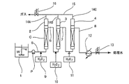
- FIG. 1 is a system diagram showing a system capable of implementing an organic compound-containing wastewater treatment method according to an embodiment of the present invention.
- reference numeral 1 denotes a storage tank for storing the organic compound-containing waste water W.
- the storage tank 1 includes a first oxidation catalyst reaction tower 2, a second oxidation catalyst reaction tower 3 filled with an oxidation catalyst C, and
- the third oxidation catalyst reaction tower 4 is connected in series through the first flow path 5, the second flow path 6 and the third flow path 7 so as to allow upward flow of water, respectively.
- the oxidation catalyst reaction tower 4 is connected to the fourth flow path 8 on the upper side.
- the first flow path 5 is provided with a pump P and first hydrogen peroxide supply means 9, and the second flow path 6 is provided with second hydrogen peroxide supply means 10.
- the third channel 7 is provided with a third hydrogen peroxide supply means 11, and the fourth channel 8 is provided with a cooler 12 and a pressure regulating valve 13.
- header pipes 14A, 14B, and 14C are attached to the tops of the first oxidation catalyst reaction tower 2, the second oxidation catalyst reaction tower 3, and the third oxidation catalyst reaction tower 4, respectively.
- 14 ⁇ / b> A, 14 ⁇ / b> B, and 14 ⁇ / b> C merge at the exhaust pipe 15.
- Reference numeral 16 denotes a pressure adjusting valve provided on the downstream side of the exhaust pipe 15.
- the oxidation catalyst C packed in the oxidation catalyst reaction towers 2, 3, and 4 is not particularly limited as long as it can exhibit an oxidation function in the presence of hydrogen peroxide.
- platinum, palladium, Noble metal catalysts such as ruthenium, iridium, rhodium, gold, silver and osmium can be used. These catalysts can be used individually by 1 type, and can also be used in combination of 2 or more type.
- supports a catalyst For example, chemical-resistant resin like a titania, a silica, an alumina, a silica alumina, a zeolite, activated carbon, polytetrafluoroethylene, etc. can be used.
- the carrier carrying the catalyst is preferably a porous carrier.
- the amount of the noble metal catalyst supported is preferably 0.05 to 10% by weight, more preferably 0.1 to 5% by weight, based on the support.
- the organic compound-containing wastewater to be treated in the present invention is wastewater containing organic compounds discharged from chemical factories, paper factories, food and beverage production factories, garbage incineration plants, human waste treatment plants, sewage treatment plants, and the like.
- the organic compound-containing waste water W stored in the storage tank 1 is heated to 100 to 180 ° C. as necessary, and then the first flow path 5 is circulated by the pump P. At this time, hydrogen peroxide solution is added from the first hydrogen peroxide supply means 9 to the organic compound-containing waste water W.
- the amount of hydrogen peroxide added at this time is 0.5 to 1 times the amount of hydrogen peroxide determined from the following equation (1) using the amount of oxygen (O) determined from the theoretical oxygen demand. .
- Oxygen amount (O) ⁇ 34/16 hydrogen peroxide amount (1)
- the amount of hydrogen peroxide added in the second hydrogen peroxide supply means 10 and the third hydrogen peroxide supply means 11 is set to be smaller than the amount added by the hydrogen peroxide supply means 9.
- the organic compound-containing waste water W is supplied to the first oxidation catalyst reaction tower 2 in an upward flow, and the organic compound-containing waste water W is brought into contact with the oxidation catalyst C.
- SV organic compound-containing waste water W at this time is 0.5 ⁇ 10h -1, is especially preferred 0.5 ⁇ 5h -1.
- the reaction time required for the decomposition of the organic compound is affected by the concentration and type of the organic compound in the organic compound-containing wastewater W, the water quality such as other components, and the water temperature. Should be selected appropriately.
- This hydrogen peroxide becomes active oxygen by the catalyst and is decomposed by the oxidative decomposition reaction of the organic compound.
- the elements C and N contained in the organic compound become CO 2 gas and N 2 gas.
- unreacted hydrogen peroxide also becomes a gas component such as oxygen gas on the surface of the oxidation catalyst C, and the organic compound-containing waste water W is circulated upward to the first oxidation catalyst reaction tower 2.
- the gas component is accumulated in the upper part of the first oxidation catalyst reaction tower 2. If this is left as it is, this gas component is brought into the second oxidation catalyst reaction tower 3 and further the third oxidation catalyst reaction tower 4 described later, and the contact efficiency between the organic compound-containing waste water W and the oxidation catalyst C is improved.
- the oxidation catalyst C does not work effectively on the decomposition of the organic compound.
- the gas component is adjusted to a predetermined pressure from the exhaust pipe 15 through the header pipe 14A by the pressure adjustment valve 16. Pressure is adjusted and discharged.
- the first stage catalytic oxidation treatment is performed from the first oxidation catalyst reaction tower 2 to the second flow path 6. Only the organic compound-containing waste water W is discharged.
- the second oxidation catalyst reaction tower 3 is passed through the second flow path 6 in the subsequent stage of the first oxidation catalyst reaction tower 2, and then the third oxidation catalyst is passed through the third flow path 7.
- the organic compounds can be decomposed by sequentially connecting the reaction towers 4 in series and performing catalytic catalytic oxidative decomposition in multiple stages (three stages) while discharging similarly generated gas.
- the hydrogen peroxide solution is provided with the second hydrogen peroxide supply means 10 in the second flow path 6 and the third hydrogen peroxide supply means 11 in the third flow path 7, respectively. It is preferable to add a hydrogen peroxide solution to each oxidation catalyst reaction tower.
- the catalytic oxidative decomposition step is multistaged, and hydrogen peroxide is added to each stage, so that active oxygen is always present in each oxidation catalyst reaction tower, and the decomposition of organic compounds is effectively promoted. be able to.
- the treated water may be cooled from the fourth flow path 8 to near normal temperature by the cooler 12 and discharged at a predetermined pressure by the pressure adjusting valve 13. Then, the treated water may be discharged to the external environment or recovered and reused after appropriately performing other necessary treatments.
- the oxidation catalyst C can be used for a long time, but when it is deteriorated, it can be reused after being activated with an acid, or can be recovered and reused as a raw material for catalyst production.
- the oxidation catalyst reaction towers are arranged in series in three stages and water is passed through the series, but if there are a plurality of stages, the oxidation catalyst reaction towers may be two stages or four or more stages.
- Example 1 As the oxidation catalyst C, three oxidation catalyst reaction columns (columns) 2, 3, and 4 filled with about 500 ml of a catalyst having 0.5 parts by weight of platinum supported on 100 parts by weight of titania spheres are connected in series, and a degassing header is connected.
- the system shown in FIG. 1 was configured by connecting the tubes 14A, 14B, and 14C to each other. Through this system, wastewater W containing organic compounds with a pH of 4 containing a TOC concentration of 526 mg / L was passed at a flow rate of 1.5 L / hr at a temperature of 160 ° C., an operating pressure of 8 kg / cm 2 , and SV3h ⁇ 1.
- the gas generated in the catalytic reaction towers 2, 3 and 4 was subjected to oxidative decomposition treatment in three stages while being discharged from the exhaust pipe 15 via the header pipes 14A, 14B and 14C.
- hydrogen peroxide was added at 2500 mg / L in the first stage, 1000 mg / L in each of the second stage and the third stage.
- Table 1 shows the results of measuring the TOC concentration of the treated water at the outlets of the oxidation catalyst reaction towers 2, 3 and 4.
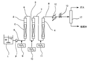
- the oxidation catalyst reaction towers (columns) 2, 3, 4 are connected in series without connecting the degassing header tubes 14 A, 14 B, 14 C, and the end of the fourth flow path 8 is connected. 2 except that a gas-liquid separator 17 is provided to separate and discharge treated water and gas components from the third oxidation catalyst reaction tower 4 via the fourth flow path 8. Configured the system shown.
- FIG. 2 the same components as those in FIG. 1 are denoted by the same reference numerals for the sake of convenience, and detailed description thereof is omitted.
- Example 1 the same organic compound-containing wastewater W as in Example 1 was passed under the same conditions, hydrogen peroxide was added under the same conditions, and oxidative decomposition treatment was performed in three stages.
- the results of measuring the TOC concentration of the treated water at the outlets of the oxidation catalyst reaction towers 2, 3 and 4 are shown in Table 1.
- oxidation catalyst reaction towers (columns) 2, 3, and 4 are connected in series, and degassing header pipes 14A, 14B, and 14C are connected to the respective oxidation catalyst reaction towers.
- Example 1 in which the oxidative decomposition process was performed in three stages while discharging the gas from the exhaust pipe 15, the TOC concentration could be reduced to 5% or less.
- Comparative Example 1 in which the treatment was performed without discharging the gas generated in each oxidation catalyst reaction tower, the TOC concentration could not be reduced to 10%.
- a large difference was observed in the TOC concentration between the first oxidation catalyst reaction tower 2 in the first stage. This is considered to be due to the difference in contact efficiency between the oxidation catalyst and the organic compound-containing waste water W depending on the presence or absence of the gas component.
Landscapes
- Chemical & Material Sciences (AREA)
- Life Sciences & Earth Sciences (AREA)
- Hydrology & Water Resources (AREA)
- Engineering & Computer Science (AREA)
- Environmental & Geological Engineering (AREA)
- Water Supply & Treatment (AREA)
- Organic Chemistry (AREA)
- Chemical Kinetics & Catalysis (AREA)
- Treatment Of Water By Oxidation Or Reduction (AREA)
Description
酸素量(O)×34/16=過酸化水素量 ・・・ (1)
また、第2の過酸化水素供給手段10及び第3の過酸化水素供給手段11における過酸化水素添加量は、過酸化水素供給手段9で添加した量よりも少ない量とする。
酸化触媒Cとしてチタニア球100重量部に白金0.5重量部を担持した触媒約500ml充填した3本の酸化触媒反応塔(カラム)2,3,4を直列に接続し、ガス抜き用のヘッダ管14A,14B,14Cをそれぞれに接続して図1に示すシステムを構成した。このシステムに対して、TOC濃度526mg/Lを含むpH4の有機化合物含有排水Wを1.5L/hrの流量で温度160℃、操作圧力8kg/cm2、SV3h-1で通水し、各酸化触媒反応塔2,3,4で発生したガスをヘッダ管14A,14B,14Cを経由して排気管15から排出しながら3段での酸化分解処理を行った。なお、過酸化水素は1段目2500mg/L、2段目、3段目それぞれ1000mg/L添加した。各酸化触媒反応塔2,3,4の出口における処理水のTOC濃度を測定した結果を表1に示す。
実施例1において、それぞれの酸化触媒反応塔(カラム)2,3,4にガス抜き用のヘッダ管14A,14B,14Cを接続することなく直列に接続し、第4の流路8の端部に気液分離器17を設けて、第3の酸化触媒反応塔4から第4の流路8を経由して処理水とガス成分とを分離排出するようにした以外は同様にして図2に示すシステムを構成した。なお、図2においては、便宜上図1と同一の構成には同一の符号を付しその詳細な説明を省略する。このシステムに対して、実施例1と同じ有機化合物含有排水Wを同一の条件で通水して同一の条件で過酸化水素を添加し、3段での酸化分解処理を行った。各酸化触媒反応塔2,3,4の出口における処理水のTOC濃度を測定した結果を表1にあわせて示す。

2…第1の酸化触媒反応塔
3…第2の酸化触媒反応塔
4…第3の酸化触媒反応塔
9…第1の過酸化水素供給手段
10…第2の過酸化水素供給手段
11…第3の過酸化水素供給手段
14A,14B、14C…ヘッダ管
15…排気管
C…酸化触媒
Claims (2)
- 有機化合物を含有する排水に過酸化水素を添加し、酸化触媒反応塔を通過させて有機化合物を接触酸化分解する有機化合物含有排水の処理方法であって、
前記酸化触媒反応塔が頂部にヘッダ管を有しており、この酸化触媒反応塔を複数直列に設けてシリーズ通水するとともに各酸化触媒反応塔のヘッダ管からガスを排出する
ことを特徴とする有機化合物含有排水の処理方法。 - 前記過酸化水素を前記複数の酸化触媒反応塔の前段でそれぞれ添加することを特徴とする請求項1に記載の有機化合物含有排水の処理方法。
Priority Applications (1)
| Application Number | Priority Date | Filing Date | Title |
|---|---|---|---|
| AU2013218880A AU2013218880B2 (en) | 2012-02-10 | 2013-02-05 | Method for treating waste water containing organic compound |
Applications Claiming Priority (2)
| Application Number | Priority Date | Filing Date | Title |
|---|---|---|---|
| JP2012027283A JP2013163150A (ja) | 2012-02-10 | 2012-02-10 | 有機化合物含有排水の処理方法 |
| JP2012-027283 | 2012-02-10 |
Publications (1)
| Publication Number | Publication Date |
|---|---|
| WO2013118702A1 true WO2013118702A1 (ja) | 2013-08-15 |
Family
ID=48947465
Family Applications (1)
| Application Number | Title | Priority Date | Filing Date |
|---|---|---|---|
| PCT/JP2013/052567 Ceased WO2013118702A1 (ja) | 2012-02-10 | 2013-02-05 | 有機化合物含有排水の処理方法 |
Country Status (3)
| Country | Link |
|---|---|
| JP (1) | JP2013163150A (ja) |
| AU (1) | AU2013218880B2 (ja) |
| WO (1) | WO2013118702A1 (ja) |
Families Citing this family (1)
| Publication number | Priority date | Publication date | Assignee | Title |
|---|---|---|---|---|
| KR102091728B1 (ko) * | 2019-08-27 | 2020-05-29 | 정영남 | 활성탄을 이용하여 황산폐산 내 과산화수소를 제거하는 체류형 연속식 분해조장치 |
Citations (10)
| Publication number | Priority date | Publication date | Assignee | Title |
|---|---|---|---|---|
| JPH06206079A (ja) * | 1993-01-08 | 1994-07-26 | Akuasu Kk | 有機塩素化合物の処理方法およびその装置 |
| JPH07328653A (ja) * | 1994-06-06 | 1995-12-19 | Kurita Water Ind Ltd | 脱窒処理方法 |
| JPH08192169A (ja) * | 1995-01-12 | 1996-07-30 | Kansai Electric Power Co Inc:The | 硝酸性窒素およびアンモニア性窒素を含む排水の処理方法 |
| JPH10305286A (ja) * | 1997-05-02 | 1998-11-17 | Tokyo Electric Power Co Inc:The | イミダゾリジノン系化合物含有水の処理方法 |
| JPH10314760A (ja) * | 1997-05-16 | 1998-12-02 | Japan Organo Co Ltd | 過酸化水素除去装置及び過酸化水素含有排水の処理方法 |
| JPH1142477A (ja) * | 1997-07-29 | 1999-02-16 | Nippon Shokubai Co Ltd | 排水の処理方法 |
| JP2000279974A (ja) * | 1999-03-31 | 2000-10-10 | Takuma Co Ltd | オゾン及び過酸化水素を用いる廃水処理方法 |
| JP2001276855A (ja) * | 2000-03-30 | 2001-10-09 | Nippon Shokubai Co Ltd | 排水の処理方法 |
| JP2003340471A (ja) * | 2002-05-27 | 2003-12-02 | Ishikawajima Harima Heavy Ind Co Ltd | 湿式触媒酸化塔 |
| JP2006000827A (ja) * | 2004-06-21 | 2006-01-05 | Japan Organo Co Ltd | 排水処理方法 |
-
2012
- 2012-02-10 JP JP2012027283A patent/JP2013163150A/ja active Pending
-
2013
- 2013-02-05 AU AU2013218880A patent/AU2013218880B2/en not_active Ceased
- 2013-02-05 WO PCT/JP2013/052567 patent/WO2013118702A1/ja not_active Ceased
Patent Citations (10)
| Publication number | Priority date | Publication date | Assignee | Title |
|---|---|---|---|---|
| JPH06206079A (ja) * | 1993-01-08 | 1994-07-26 | Akuasu Kk | 有機塩素化合物の処理方法およびその装置 |
| JPH07328653A (ja) * | 1994-06-06 | 1995-12-19 | Kurita Water Ind Ltd | 脱窒処理方法 |
| JPH08192169A (ja) * | 1995-01-12 | 1996-07-30 | Kansai Electric Power Co Inc:The | 硝酸性窒素およびアンモニア性窒素を含む排水の処理方法 |
| JPH10305286A (ja) * | 1997-05-02 | 1998-11-17 | Tokyo Electric Power Co Inc:The | イミダゾリジノン系化合物含有水の処理方法 |
| JPH10314760A (ja) * | 1997-05-16 | 1998-12-02 | Japan Organo Co Ltd | 過酸化水素除去装置及び過酸化水素含有排水の処理方法 |
| JPH1142477A (ja) * | 1997-07-29 | 1999-02-16 | Nippon Shokubai Co Ltd | 排水の処理方法 |
| JP2000279974A (ja) * | 1999-03-31 | 2000-10-10 | Takuma Co Ltd | オゾン及び過酸化水素を用いる廃水処理方法 |
| JP2001276855A (ja) * | 2000-03-30 | 2001-10-09 | Nippon Shokubai Co Ltd | 排水の処理方法 |
| JP2003340471A (ja) * | 2002-05-27 | 2003-12-02 | Ishikawajima Harima Heavy Ind Co Ltd | 湿式触媒酸化塔 |
| JP2006000827A (ja) * | 2004-06-21 | 2006-01-05 | Japan Organo Co Ltd | 排水処理方法 |
Also Published As
| Publication number | Publication date |
|---|---|
| AU2013218880A1 (en) | 2014-09-25 |
| AU2013218880B2 (en) | 2017-12-07 |
| JP2013163150A (ja) | 2013-08-22 |
Similar Documents
| Publication | Publication Date | Title |
|---|---|---|
| JP5446400B2 (ja) | 過酸化水素水処理装置 | |
| JP5447378B2 (ja) | 有機物含有水の処理方法及び装置 | |
| CN104891713B (zh) | 有机废水臭氧催化氧化处理工艺 | |
| Quesada-Peñate et al. | Degradation of paracetamol by catalytic wet air oxidation and sequential adsorption–catalytic wet air oxidation on activated carbons | |
| CN109890766B (zh) | 水处理方法及装置 | |
| CN113908777A (zh) | 多级环流臭氧催化氧化反应装置及催化氧化方法 | |
| EP3359271B1 (en) | Systems and methods for degassing of sulfur | |
| WO2013118702A1 (ja) | 有機化合物含有排水の処理方法 | |
| JP5919960B2 (ja) | 有機物含有水の処理方法 | |
| JP2012206122A (ja) | 排水の処理方法 | |
| JP4066527B2 (ja) | 過酸化水素とアンモニアとを含む排水の処理法 | |
| JPH11300374A (ja) | 排水の処理方法 | |
| JP3739452B2 (ja) | アミン化合物を含む発電所排水の処理方法 | |
| JP3457143B2 (ja) | イミダゾリジノン系化合物含有水の処理方法 | |
| JP4223706B2 (ja) | 排水の処理方法 | |
| JPH0454515B2 (ja) | ||
| JP3568298B2 (ja) | アミン化合物を含有する発電所排水の処理方法 | |
| JP4390357B2 (ja) | アンモニア含有水の処理方法 | |
| JP2013237944A (ja) | 架橋カタラーゼ固定化繊維および超純水製造装置 | |
| JPH08290007A (ja) | 溶存酸素の除去方法 | |
| JP2003145136A (ja) | 廃水の処理方法及び処理装置 | |
| JP2519122B2 (ja) | 液体中の溶存酸素の除去方法及び装置 | |
| Audirac et al. | Modelling of succinic acid heterogeneous catalytic ozonation on metallic foam | |
| JP2003117543A (ja) | 過酸化水素およびアンモニア含有廃水の浄化装置および浄化方法 | |
| JPH04330999A (ja) | 汚泥の処理方法 |
Legal Events
| Date | Code | Title | Description |
|---|---|---|---|
| 121 | Ep: the epo has been informed by wipo that ep was designated in this application |
Ref document number: 13746049 Country of ref document: EP Kind code of ref document: A1 |
|
| NENP | Non-entry into the national phase |
Ref country code: DE |
|
| WWE | Wipo information: entry into national phase |
Ref document number: IDP00201405317 Country of ref document: ID |
|
| ENP | Entry into the national phase |
Ref document number: 2013218880 Country of ref document: AU Date of ref document: 20130205 Kind code of ref document: A |
|
| 122 | Ep: pct application non-entry in european phase |
Ref document number: 13746049 Country of ref document: EP Kind code of ref document: A1 |