WO2013115138A1 - 熱間加工用工具及びその製造方法 - Google Patents
熱間加工用工具及びその製造方法 Download PDFInfo
- Publication number
- WO2013115138A1 WO2013115138A1 PCT/JP2013/051773 JP2013051773W WO2013115138A1 WO 2013115138 A1 WO2013115138 A1 WO 2013115138A1 JP 2013051773 W JP2013051773 W JP 2013051773W WO 2013115138 A1 WO2013115138 A1 WO 2013115138A1
- Authority
- WO
- WIPO (PCT)
- Prior art keywords
- plating film
- tool
- hot working
- hot
- plating
- Prior art date
- Legal status (The legal status is an assumption and is not a legal conclusion. Google has not performed a legal analysis and makes no representation as to the accuracy of the status listed.)
- Ceased
Links
Images


Classifications
-
- C—CHEMISTRY; METALLURGY
- C25—ELECTROLYTIC OR ELECTROPHORETIC PROCESSES; APPARATUS THEREFOR
- C25D—PROCESSES FOR THE ELECTROLYTIC OR ELECTROPHORETIC PRODUCTION OF COATINGS; ELECTROFORMING; APPARATUS THEREFOR
- C25D3/00—Electroplating: Baths therefor
- C25D3/02—Electroplating: Baths therefor from solutions
- C25D3/56—Electroplating: Baths therefor from solutions of alloys
- C25D3/562—Electroplating: Baths therefor from solutions of alloys containing more than 50% by weight of iron or nickel or cobalt
-
- B—PERFORMING OPERATIONS; TRANSPORTING
- B21—MECHANICAL METAL-WORKING WITHOUT ESSENTIALLY REMOVING MATERIAL; PUNCHING METAL
- B21B—ROLLING OF METAL
- B21B25/00—Mandrels for metal tube rolling mills, e.g. mandrels of the types used in the methods covered by group B21B17/00; Accessories or auxiliary means therefor ; Construction of, or alloys for, mandrels or plugs
-
- C—CHEMISTRY; METALLURGY
- C25—ELECTROLYTIC OR ELECTROPHORETIC PROCESSES; APPARATUS THEREFOR
- C25D—PROCESSES FOR THE ELECTROLYTIC OR ELECTROPHORETIC PRODUCTION OF COATINGS; ELECTROFORMING; APPARATUS THEREFOR
- C25D5/00—Electroplating characterised by the process; Pretreatment or after-treatment of workpieces
- C25D5/48—After-treatment of electroplated surfaces
- C25D5/50—After-treatment of electroplated surfaces by heat-treatment
Definitions
- the present invention relates to a hot working tool and a manufacturing method thereof, and more particularly, to a hot working tool used for manufacturing a metal and a manufacturing method thereof.
- Hot working tools used for metal production are generally required to have seizure resistance.
- a hot working tool used in the Mannesmann pipe manufacturing method which is a method for manufacturing a seamless pipe, is used in a harsh environment, and therefore requires excellent seizure resistance.
- the Mannesmann tube process utilizes various hot working tools.
- a mandrel bar is used as a hot working tool.
- a mandrel bar is provided in the mandrel mill.
- the mandrel bar receives heat from a steel (element tube) at about 1200 ° C. during rolling by a mandrel mill, and further receives a surface pressure of 20 to 30 kgf / mm 2 .
- Mandrel bars are used in harsh environments and are susceptible to damage such as seizure.
- Patent Document 1 Japanese Patent Application Laid-Open No. 2000-244631 (Patent Document 1) and International Publication WO 2004/108311 (Patent Document 2), a Cr plating film is formed on the surface of the substrate.
- Patent Document 2 a Cr plating film is formed on the surface of the substrate.
- These references further define the axial and circumferential centerline average roughness Ra and maximum depth Rv on the Cr plating film surface. According to these rules, the occurrence of seizure is suppressed and the service life is increased.
- Patent Document 3 JP-A-5-253613 (Patent Document 3), a nitriding treatment is performed on a mandrel bar base material. It is described that by increasing the surface hardness of the mandrel bar by nitriding treatment, seizure hardly occurs and wear resistance increases.
- Patent Document 4 instead of the Cr plating film and nitriding treatment, a film made of a Ni-based alloy containing tungsten (W) is formed on the surface of the mandrel bar substrate.
- a film made of a Ni-based alloy containing W is described as having hardness and peeling resistance superior to those of a Cr plating film and a nitride layer.
- the Cr plating films disclosed in Patent Documents 1 and 2 tend to decrease in hardness when repeatedly used in a high temperature environment. Furthermore, when the Cr plating film is manufactured by an electroplating method, the Cr plating film has a large electrodeposition stress (residual tensile stress). Therefore, many cracks may occur on the Cr plating surface. If there are many cracks, the plating film is easily worn and peeled off. Therefore, the seizure resistance is reduced.
- the nitriding treatment disclosed in Patent Document 3 is difficult to implement on a large hot working tool such as a mandrel bar. Even if the nitriding treatment can be performed on the hot working tool, distortion is likely to occur in the hot working tool due to the nitriding treatment, and the dimensional accuracy tends to decrease.
- An object of the present invention is to provide a tool for hot working having excellent seizure resistance.
- the hot working tool includes a base material and a plating film.
- the plating film is formed on the substrate surface.
- the plating film contains W: 36 to 44% by mass%, the balance is made of Ni and impurities, and the Vickers hardness is 900 or more.
- the plating film has a thickness of 15 ⁇ m or more.
- the method of manufacturing a hot working tool includes a step of preparing a base material for the hot working tool, and the surface of the base material contains W: 36 to 44% by mass, with the balance being Ni. And a plating step for forming a plating film made of impurities, and a heat treatment step for heat-treating the base material on which the plating film is formed so that the Vickers hardness of the plating film is 900 or more.
- the hot working tool according to the present embodiment is excellent in seizure resistance.
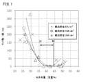
- FIG. 1 is a diagram showing the relationship between the W content of the plating film and the number of cracks (pieces / cm) formed in the plating film.
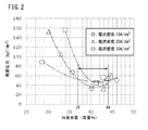
- FIG. 2 is a diagram showing the relationship between the W content of the plating film and the electrodeposition stress (kgf / mm 2 ) of the plating film.
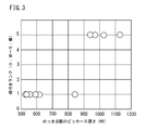
- FIG. 3 is a diagram showing the relationship between the Vickers hardness of the plating film and the seizure resistance.
- FIG. 4 is a diagram showing the relationship between the W concentration ratio (mol%) in the metal component of the aqueous electrolyte solution and the W content (mass%) in the formed plating film.
- FIG. 1 is a diagram showing the relationship between the W content of the plating film and the number of cracks (pieces / cm) formed in the plating film.
- FIG. 2 is a diagram showing the relationship between the W content of the plating film and the electrodeposition stress (kgf / mm 2 ) of the plating film.
- FIG. 3 is a diagram showing
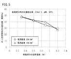
- FIG. 5 is a diagram showing the relationship between the total concentration (M) of metal components in the aqueous electrolyte solution and the W content (mass%) in the plating film.
- FIG. 6 is a diagram showing the relationship between the in-furnace time of the substrate at each furnace temperature and the Vickers hardness of the plating film.
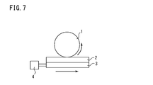
- FIG. 7 is a schematic diagram of a seizure resistance evaluation test in Examples.
- the hot working tool includes a base material and a plating film.
- Hot working tools are tools that are widely available for hot working of metals. Examples of the hot working tool include a mandrel bar used in a mandrel mill manufactured by the Mannesmann tube method, a plug, a disk roll, a guide shoe, and the like used for piercing and rolling.
- the substrate has a well-known chemical composition.
- the base material has, for example, the same chemical composition as an alloy tool steel material defined in JIS G4404 (2006).
- the chemical composition of the substrate is, for example, SKD61 in terms of mass%: C: 0.35 to 0.42%, Si: 0.80 to 1.20%, Mn: 0.25 to 0.50%, P: 0 0.030% or less, S: 0.02% or less, Cr: 4.8 to 5.50%, Mo: 1.00 to 1.50%, V: 0.80 to 1.15%, the balance Consists of Fe and impurities.
- the substrate may have other chemical composition different from the chemical composition defined in JIS G4404 (2006).
- the plating film according to the present embodiment is formed on the substrate surface.
- the plating film is formed by an electroplating method described later.
- the plating film according to the present embodiment is made of a Ni-based alloy containing W. Specifically, the plating film contains W: 36-44% by mass, and the balance consists of nickel (Ni) and impurities. The reason why the W content is set to 36 to 44% is as follows.
- FIG. 1 is a diagram showing the relationship between the W content of the plating film and the number of cracks (pieces / cm) formed in the plating film.
- FIG. 2 is a diagram showing the relationship between the W content of the plating film and the electrodeposition stress (kgf / mm 2 ) of the plating film.
- plating films having various W contents were formed on the substrate by the electroplating method described later. Of the chemical composition of the plating film, other than W were Ni and impurities.
- plating films having various chemical compositions were prepared with three kinds of current densities of 5 A / dm 2 , 10 A / dm 2 , and 20 A / dm 2 .
- plating films having various chemical compositions were produced at three current densities of 10 A / dm 2 , 20 A / dm 2 , and 30 A / dm 2 . After producing the plating film, the number of cracks generated in the plating film was counted.
- FIG. 1 was created using the W content of each plating film and the number of cracks obtained.
- the electrodeposition stress (kgf / mm 2 ) of the prepared plating film was measured using a spiral plating stress meter manufactured by Yamamoto Kakin Tester Co., Ltd.
- FIG. 2 was created using the W content of each plating film and the obtained electrodeposition stress.
- the electrodeposition stress was 60 kgf / mm 2 or less.
- the electrodeposition stress is remarkably reduced, and as a result, the number of cracks is also remarkably reduced.
- the electrodeposition stress is 60 kgf / mm 2 or less and the number of cracks is less than 50 / cm. Therefore, the plating film is not easily peeled off and is not easily worn. Therefore, the seizure resistance of the plating film is increased. If the W content is less than 36% or exceeds 44%, the electrodeposition stress is remarkably increased and the number of cracks is increased. Therefore, wear resistance is reduced and seizure resistance is also reduced.
- the lower limit of the preferred W content is higher than 36%, more preferably 38%.
- the upper limit of the preferable W content is less than 44%, more preferably 42%.
- the plating film is amorphous.
- an intermetallic compound Ni, W
- Ni and W an intermetallic compound containing Ni and W is precipitated in the plating film. It is estimated that the hardness of the plating film is increased by this intermetallic compound.
- the hardness of the plating film is 900 or more in terms of Vickers hardness.
- Vickers hardness is measured by the following method. In the plated film of the obtained hot working tool, five arbitrary regions are selected. In each selected area, Vickers hardness (HV) is measured according to JIS Z2244 (2009). The test temperature is room temperature (25 ° C.) and the test force is 0.03 kgf. The average of the obtained values (5 in total) is defined as the Vickers hardness of the hot working tool.
- FIG. 3 is a diagram showing the relationship between the Vickers hardness of the plating film and the seizure resistance.
- FIG. 3 was created from the test results of the seizure resistance evaluation test in Examples described later.
- test materials hot tool test materials corresponding to mandrel bars having plating films with various hardnesses were produced.
- the chemical composition of the produced plating film is all within the range of the chemical composition of the plating film according to the present embodiment (that is, the chemical composition containing 36 to 44% W and the balance being Ni and impurities). It was.
- Each produced hot tool test material was rolled with a test apparatus for evaluating seizure resistance. The surface of each hot tool test material after rolling was visually observed to confirm the presence or absence of seizure and the seizure state.
- the seizure state was defined as follows. When significant seizure occurred over the entire length of the rolled part of the hot tool test material, it was evaluated as rank “0”. When seizure shallower than rank “0” was observed over the entire length of the rolled portion of the hot tool test material, it was evaluated as rank “1”. Although seizure did not occur over the entire length of the rolled part of the hot tool test material, it was evaluated as rank “2” when seizure occurred at the edge and center of the rolled part. When the seizure occurred only at the edge portion of the rolled portion of the hot tool test material, the rank was evaluated as “3”.
- the Vickers hardness of a plating film is 900 (HV) or more.
- the Vickers hardness of the plating film is 920 (HV) or higher or higher than 920 (HV), more preferably 940 (HV) or higher or higher than 940 (HV), more preferably 950 (HV). Above or higher than 950 (HV).
- the preferred film thickness of the plating film is 15 microns ( ⁇ m) or more. If the film thickness is too small, it is easy to wear and seizure is likely to occur. A more preferable film thickness of the plating film is 20 ⁇ m or more. If the film thickness is thick, the baking resistance is improved, but if it is too thick, the upper limit of the preferable film thickness is 100 ⁇ m, more preferably 80 ⁇ m, considering that the peeling of the plating tends to occur and the manufacturing cost. . Furthermore, the upper limit of a preferable film thickness is 50 micrometers. The film thickness of the plating film can be adjusted by adjusting the plating treatment time described later.
- the method for manufacturing a hot working tool includes a step of preparing a base material (base material preparation step), a step of forming a plating film on the surface of the base material by plating treatment (plating step), and a plating film. And a step of performing a heat treatment on the formed substrate (heat treatment step).
- Base material preparation process A substrate having the chemical composition described above is prepared.
- the base material is manufactured in the shape of a desired hot working tool by hot working and / or cold working. After the hot working or cold working, the base material may be quenched and tempered. Further, other heat treatment may be performed.
- the substrate surface is degreased by a known method.
- Degreasing is, for example, cathodic electrolytic degreasing.
- a well-known pickling process is implemented with respect to the base-material surface after degreasing.
- the surface roughness of the substrate may be adjusted by blasting the substrate surface.
- a plating film is formed on the prepared substrate by electroplating to form a plating film.
- a plating bath made of an aqueous electrolyte solution is prepared.
- the aqueous electrolyte solution contains tungsten (W acid ions), nickel (Ni ions), and a citric acid compound.
- W acid ions tungsten
- Ni ions nickel
- citric acid compound tungsten (W acid ions)
- W acid ions zinc
- Ni ions nickel
- citric acid compound a citric acid compound
- sodium tungstate dihydrate, nickel sulfate hexahydrate, and triammonium citrate the above aqueous electrolyte solution is formed.
- metal salt hydrates that produce W are, for example, potassium tungstate.
- metal salt hydrates that produce Ni are, for example, nickel sulfate heptahydrate, nickel chloride hexahydrate, nickel formate dihydrate, and the like.
- Other citric acid compounds are, for example, citric acid, diammonium citrate, trisodium citrate and the like. As appropriate, it can be used by an appropriate combination of each concentration.
- the aqueous electrolyte solution may contain sulfuric acid or sodium hydroxide in order to adjust the pH.
- the total concentration of metal components (W acid ions and Ni ions) in the aqueous electrolyte solution and the concentration ratio of W in the metal components are adjusted so that the W content of the formed plating film is 36 to 44%.
- a preferred W acid ion concentration ratio (hereinafter referred to as W concentration ratio) to metal components (W acid ions and Ni ions) is 55 to 75 mol%, and a more preferable lower limit of the W concentration ratio is 60 mol%.
- a preferable upper limit of the W concentration ratio is 70 mol%.
- the preferable pH of the aqueous electrolyte solution is 4 to 6, more preferably 4.5 to 5.5.
- a preferable temperature of the aqueous electrolyte solution is 50 to 70 ° C., and more preferably 55 to 65 ° C. In order to increase the plating current efficiency, the pH and temperature are preferably higher.
- a plating film having a W content of 36 to 44% can be formed.
- FIG. 4 and 5 are diagrams showing an example of conditions of an aqueous electrolyte solution that can form the above-described plating film.
- FIG. 4 shows the W in the metal component of the aqueous electrolyte solution when the total concentration of the metal components in the aqueous electrolyte solution having the above composition is 0.6 M, the pH of the aqueous electrolyte solution is 5, and the temperature of the aqueous electrolyte solution is 60 ° C. It is a figure which shows the relationship between a density
- FIG. 4 shows the W in the metal component of the aqueous electrolyte solution when the total concentration of the metal components in the aqueous electrolyte solution having the above composition is 0.6 M, the pH of the aqueous electrolyte solution is 5, and the temperature of the aqueous electrolyte solution is 60 ° C. It is a figure which shows the relationship between a density
- the W content in the plating film is 36 to 44%.
- the W content of the plating film is 36 to 44%.
- a preferred current density during the plating treatment is 10 to 30 A / dm 2 . If the current density is too low, it is difficult to form a plating film. If the current density is too high, the electrodeposition stress of the plating film increases and cracks are likely to occur in the plating film.
- the current efficiency of the aqueous electrolyte solution according to this embodiment is about 40%, which corresponds to about twice the current efficiency of conventional Cr plating. Therefore, the plating treatment according to the present embodiment can form a plating film in a short time compared to conventional Cr plating.
- a plating film is formed on the substrate surface by the above-described plating treatment.
- the formed plating film contains 36 to 44% W, and the balance is made of Ni and impurities.
- the film thickness of a plating film can be adjusted based on plating processing time.
- Heat treatment process Heat treatment is performed on the substrate on which the plating film is formed, and the Vickers hardness of the plating film is set to 900 or more.
- FIG. 6 is a diagram showing the relationship between the in-furnace time of the substrate at each furnace temperature and the Vickers hardness of the plating film.
- FIG. 6 was obtained by the following method.
- a substrate having a plating film satisfying the chemical composition of this embodiment (that is, a chemical composition containing 36 to 44% W and the balance being Fe and impurities) was prepared.
- the prepared base material was heat-treated at various furnace temperatures and in-furnace times to produce hot working tools.
- the Vickers hardness of the plating film of each manufactured tool for hot working was measured according to JIS Z2244 (2009).
- FIG. 6 was created using the obtained Vickers hardness.
- the mark “ ⁇ ” in FIG. 6 indicates the result when the furnace temperature is 300 ° C.
- ⁇ indicates that the furnace temperature is 400 ° C.
- ⁇ indicates that the furnace temperature is 500 ° C.
- ⁇ indicates that the furnace temperature is 600 ° C.
- ⁇ indicates that the furnace temperature is 700 ° C.
- ⁇ indicates the case where the furnace temperature is 900 ° C., respectively.
- the Vickers hardness of the plating film is less than 900 even if the in-furnace time is increased. Therefore, in order to make the Vickers hardness of the plating film 900 or more, it is necessary to increase the furnace temperature.
- the lower limit of the furnace temperature is set to 350 ° C. If the furnace temperature is 350 ° C. or more, the Vickers hardness of the plating film can be made 900 or more by adjusting the in-furnace time.
- the in-furnace time in FIG. When the furnace temperature is low, for example, when the furnace temperature in FIG. 6 is 400 ° C. or 500 ° C., the Vickers hardness of the plating film gradually increases as the in-furnace time elapses. On the other hand, when the furnace temperature is high, for example, when the furnace temperature in FIG. Decreases over time.
- the in-furnace time P (min) satisfies the formula (1). 5 ⁇ 10 10 ⁇ T ⁇ 3.55 ⁇ P ⁇ 2 ⁇ 10 11 ⁇ T ⁇ 3.39 (1)
- T is the furnace temperature (° C.).
- the in-furnace time P is the time from when the base material is charged into the heat treatment furnace until the base material is extracted from the heat treatment furnace.
- the Vickers hardness of the plating film becomes 900 or more.
- a preferable furnace temperature is 700 ° C. or less.
- the base material has the same chemical composition as the alloy tool steel material specified in JIS G4404 (2006), when the furnace temperature in heat treatment exceeds 700 ° C., the hardness of the base material decreases. If the hardness of a base material falls, the impact resistance of a base material will fall and it will become easy to deform
- the upper limit of a preferable furnace temperature is less than 700 degreeC.
- a preferable lower limit of the Vickers hardness of the substrate is 300. The upper limit with preferable Vickers hardness of a base material is not specifically limited. A preferable upper limit of the Vickers hardness of the substrate is, for example, 550.
- a more preferable upper limit of the furnace temperature is 640 ° C.
- a quenching and tempering process may be performed on the base material before the plating process.
- the tempering temperature is 640 ° C. If heat treatment is performed on the base material after the plating process at a furnace temperature equal to or higher than the tempering temperature, the effect of tempering disappears and the strength and toughness of the base material change. Therefore, the preferable upper limit of the furnace temperature is 640 ° C.
- a more preferable upper limit of the furnace temperature is 600 ° C.
- the range of the in-furnace time in which the Vickers hardness can be 900 or higher is narrower than when the furnace temperature is 600 ° C. or lower. Therefore, if the furnace temperature is high, it is necessary to accurately control the in-furnace time in actual operation.
- the furnace temperature is 600 ° C. or lower, the range of the in-furnace time in which the Vickers hardness can be 900 or more is wide, so that it is easy to adjust the Vickers hardness even in actual operation.
- the preferable lower limit of the furnace temperature is 400 ° C.
- the range of the in-furnace time that allows the Vickers hardness to be 900 or higher is wide.
- a preferable furnace temperature range is 400 ° C. to 600 ° C. Within this range, it is not necessary to manage the in-furnace time with high accuracy, and the Vickers hardness can be easily adjusted to 900 or more even if various disturbances exist in actual operation.
- the in-furnace time is preferably within 60 minutes in consideration of productivity.
- the heat treatment atmosphere in the heat treatment furnace is not particularly limited, and is a known heat treatment atmosphere.
- the plating film is heat-treated at a furnace temperature of 350 ° C. or higher so that the Vickers hardness of the plating film is 900 or more. If the furnace temperature is 350 ° C. or higher and the in-furnace time satisfies the formula (1), the material temperature of the plating film also becomes 350 ° C. or higher. If the material temperature is maintained at 350 ° C. or higher, it is estimated that the hardness of the plating film increases and the Vickers hardness becomes 900 or higher.
- the furnace temperature of the heat treatment furnace immediately after the base material is charged varies depending on the size of the heat treatment furnace and the shape, size and temperature of the base material charged in the heat treatment furnace.
- the heat treatment furnace according to the present embodiment assumes that the maximum reduction in furnace temperature when a normal temperature (25 ° C.) base material is inserted is within 20% of the set furnace temperature.
- the hot working tool is manufactured by the above process.
- the produced hot working tool is excellent in seizure resistance.
- Hot working tools were manufactured under various manufacturing conditions, and seizure resistance was evaluated.
- the base materials for each test number had the following specifications.
- the chemical composition of the substrate corresponded to SKD61 specified in JIS G4404 (2006).
- the substrate dimensions were 24.5 mm wide, 15 mm high, and 150 mm long.
- the surface roughness of the base material was 3 ⁇ m in arithmetic average roughness Ra defined in JIS B0601 (2001), and 10 ⁇ m in 10-point average roughness Rz defined in JIS B0601 (1994).
- the base material was manufactured by the following method. An ingot having the above chemical composition was melted. The ingot was hot-worked to produce a substrate having the above-described dimensions. Blasting with grid Fe spheres was performed on the manufactured substrate surface to adjust the surface roughness.
- the surface of the manufactured substrate was washed. Specifically, cathode electrolytic degreasing was performed on the substrate surface. A 5 mass% NaOH aqueous solution was used for the electrolytic bath. The substrate was immersed in an electrolytic bath as a cathode. Then, cathodic electrolytic degreasing was performed at a current density of 4 A / dm 2 for 10 seconds.
- the pickling process was implemented with respect to the base-material surface after electrolytic degreasing.
- a pickling bath composed of a 4 vol% sulfuric acid aqueous solution was prepared. The substrate was immersed in the pickling bath for 5 to 10 seconds. The substrate was pulled up and the substrate surface was washed with tap water.
- the resulting base material was plated under the conditions shown in Table 1 (current density, total concentration of metal components, W concentration ratio). Specifically, an aqueous electrolyte solution having a metal component total concentration (M: mol / L) and a W concentration ratio (mol%) shown in Table 1 was prepared.
- the aqueous electrolyte solution was prepared by mixing 0.2 to 0.8M sodium tungstate dihydrate, 0.1 to 0.4M nickel sulfate hexahydrate, and 0.3 to 1.2M triammonium citrate. Produced.
- the liquid temperature of the aqueous electrolyte solution was 60 ° C.
- the pH of the aqueous electrolyte solution was 5. In addition, only the test number 11 made the plating treatment time longer than the other test numbers, and only the test number 18 made the plating treatment time shorter than the other test numbers.
- the substrates of Test Nos. 1 to 18 were subjected to heat treatment under the heat treatment conditions (furnace temperature and in-furnace time) shown in Table 1.
- Pmin and Pmax in Table 1 were calculated based on the following formulas (2) and (3).
- Pmin 5 ⁇ 10 10 ⁇ T ⁇ 3.55
- Pmax 2 ⁇ 10 11 ⁇ T ⁇ 3.39 (3)
- Pmin is the left side of equation (1)
- Pmax is the right side of equation (1).
- a base material at room temperature (25 ° C.) was charged into a heat treatment furnace having the furnace temperature shown in Table 1.
- the maximum reduction in furnace temperature immediately after charging was less than 20% of the furnace temperature shown in Table 1.
- the in-furnace time was defined as the time (min) from when the base material was charged into the heat treatment furnace until extraction. After the in-furnace time (min) shown in Table 1, the substrate was extracted from the heat treatment furnace and allowed to cool in the atmosphere.
- the film thickness of the plating film of the obtained hot working tool was measured by the following method.
- the substrate was cut to prepare a sample including a cross section including a plating film.
- the film thickness of the plating film was measured by SEM observation using the obtained sample.
- the film thickness ( ⁇ m) was the average of values measured at a pitch of 100 ⁇ m in the range of 1000 ⁇ m on the substrate surface.
- Electrodeposition stress measurement test The electrodeposition stress of the plating film of the hot working tool of each test number was measured using a spiral plating stress meter manufactured by Yamamoto Kakin Tester Co., Ltd. The measurement was performed 3 times. The average of the measured values (three in total) was taken as the electrodeposition stress of the hot working tool with the test number.
- a test apparatus for evaluation of seizure resistance shown in FIG. 7 was prepared.
- the test apparatus was provided with a roll 1, a rolled material 2, a hot working tool 3 for each test number, and a cylinder 4.
- the material of the rolled material 2 corresponded to SUS304 defined in JIS G4304 (2005).
- the dimensions of the rolled material 2 were a width of 24.5 mm, a height of 15 mm, and a length of 150 mm.
- the surface roughness of the rolled material 2 was 1 to 2 ⁇ m in terms of arithmetic average roughness Ra.
- the diameter of roll 1 was 150 mm.
- Rolled material 2 was charged into a heating furnace in a nitrogen atmosphere and heated at 1200 ° C.
- the rolled material 2 heated to 1200 ° C. was extracted from the heating furnace.
- the extracted rolled material 2 was disposed on the hot working tool 3, and the roll 1 was disposed on the rolled material 2.
- a cylinder 4 was disposed at the rear end of the hot working tool 3.
- Roll 1 was rotated at 30 rpm in the direction of the arrow in FIG. 7, and rolled material 2 was rolled at a roll reduction rate of 30%.
- the rear end of the hot working tool 3 was pushed by the cylinder 4 to move the hot working tool 3 in the direction of the arrow at 30 mm / s. Since the moving speed of the rolled material 2 is different from the moving speed of the hot working tool 3, the hot working tool 3 slid relative to the rolled material 2.
- a known lubricant was applied to the surface of the hot working tool 3 of each test number and dried.
- the W content of the plating films of test numbers 1 to 11 was within the scope of the present invention. Furthermore, the furnace temperature in the heat treatment was within the scope of the present invention, and the in-furnace time satisfied the formula (1). Therefore, the Vickers hardness of the plating film was 900 or more. As a result, the electrodeposition stress was as low as 60 kgf / mm 2 or less, and the number of cracks was less than 50 / cm.
- the W content and Vickers hardness of the plating films of test numbers 10 and 11 were within the scope of the present invention, and the seizure resistance was also good (rank 5). However, since the furnace temperature in the heat treatment of test numbers 10 and 11 exceeded 700 ° C., the Vickers hardness of the base material was low and less than 400.
- test number 13 the furnace temperature in the heat treatment was less than 350 ° C. Therefore, the Vickers hardness of the plating film was less than 900. Therefore, the seizure resistance was as low as rank 2.
- test numbers 14 and 17 the W concentration ratio in the electrolytic aqueous solution for plating was too low. Therefore, the W content of the plating film is less than the lower limit of the present invention. Therefore, the electrodeposition stress exceeded 60 kgf / mm 2 and the number of cracks was 50 or more. Therefore, the seizure resistance was low.
- Test No. 17 not only was the W concentration ratio in the electrolytic aqueous solution too low, but also the current density was high, so the Vickers hardness was less than 900 HV. Therefore, the seizure resistance was low.
- test number 15 the W concentration ratio in the electrolytic aqueous solution for plating was too high. Therefore, the W content of the plating film exceeded the upper limit of the present invention. Therefore, the electrodeposition stress exceeded 60 kgf / mm 2 and the number of cracks was 50 or more. Therefore, the seizure resistance was low.
- test number 16 the total concentration of the metal components in the electrolytic aqueous solution for plating was too high. Therefore, the W content of the plating film is less than the lower limit of the present invention. Therefore, the electrodeposition stress exceeded 60 kgf / mm 2 and the number of cracks was 50 or more. Therefore, the seizure resistance was low.
- the thickness of the plating film was 10 ⁇ m and was too thin. Therefore, the seizure resistance was low and rank 0.
- test number 19 no heat treatment was performed. Therefore, the Vickers hardness of the plating film was less than 900. Therefore, the seizure resistance was low and rank 0.
- the hot working tool in the present embodiment can be widely used for hot working of metals.
- it is suitable as a tool for hot working such as a mandrel bar used in the Mannesmann pipe manufacturing method.
Landscapes
- Chemical & Material Sciences (AREA)
- Engineering & Computer Science (AREA)
- Chemical Kinetics & Catalysis (AREA)
- Electrochemistry (AREA)
- Materials Engineering (AREA)
- Metallurgy (AREA)
- Organic Chemistry (AREA)
- Mechanical Engineering (AREA)
- Electroplating Methods And Accessories (AREA)
Abstract
耐焼付き性に優れた熱間加工用工具を提供する。本実施形態による熱間加工用工具は、基材と、めっき皮膜とを備える。鍍金皮膜は、基材表面に形成される。めっき皮膜はさらに、質量%でW:36~44%を含有し、残部はNi及び不純物からなり、ビッカース硬さが900以上である。好ましくは、900以上のビッカース硬さのめっき皮膜は、350℃以上の炉温及び1時間以内の在炉時間で熱処理されることにより形成される。
Description
本発明は、熱間加工用工具及びその製造方法に関し、さらに詳しくは、金属の製造に利用される熱間加工用工具及びその製造方法に関する。
金属の製造に利用される熱間加工用工具は一般的に、耐焼付き性を要求される。特に、継目無管の製造方法であるマンネスマン製管法に利用される熱間加工用工具は、過酷な環境下で使用されるため、優れた耐焼付き性が要求される。
マンネスマン製管法は種々の熱間加工用工具を利用する。たとえば、マンネスマン製管法では、熱間加工用工具としてマンドレルバーを利用する。マンドレルバーはマンドレルミルに備えられる。マンドレルバーは、マンドレルミルによる圧延時に、1200℃程度の鋼(素管)から熱を受け、さらに、20~30kgf/mm2の面圧を受ける。マンドレルバーの使用環境は過酷であり、焼付き等の損傷が生じやすい。
マンドレルバー等の熱間加工用工具の耐焼付き性等を高める技術は、次のとおり提案されている。
特開2000-246312号公報(特許文献1)及び国際公開WO2004/108311号(特許文献2)に開示されたマンドレルバーでは、基材表面にCrめっき皮膜が形成される。これらの文献はさらに、Crめっき皮膜表面における軸方向及び円周方向の中心線平均粗さRa及び最大深さRvを規定する。これらの規定により、焼付きの発生が抑制され、耐用寿命が高まると記載されている。
特開平5-253613号公報(特許文献3)では、マンドレルバー基材に対して窒化処理を実施する。窒化処理によりマンドレルバーの表面の硬度を高めることにより、焼付きが発生しにくく耐摩耗性が高まると記載されている。
特開平8-47714号公報(特許文献4)では、Crめっき皮膜及び窒化処理に代えて、タングステン(W)を含有したNi基合金からなる皮膜をマンドレルバー基材表面に形成する。Wを含有するNi基合金からなる皮膜は、Crめっき皮膜及び窒化層よりも優れた硬度及び耐剥離性を有すると記載されている。
しかしながら、特許文献1及び2に開示されるCrめっき皮膜は、高温の環境下で繰り返し使用すると、硬度が低下しやすい。さらに、Crめっき皮膜が電気めっき法により製造される場合、Crめっき皮膜は大きな電着応力(残留引張応力)を有する。そのため、Crめっき表面に多数のクラックが発生する場合がある。クラックが多数存在すれば、めっき皮膜が摩耗しやすく、剥離しやすい。そのため、耐焼付き性が低下する。
特許文献3に開示される窒化処理は、マンドレルバーのような大型の熱間加工用工具に対して実施しにくい。仮に、熱間加工用工具に窒化処理を実施できても、窒化処理により熱間加工用工具に歪みが生じやすく、寸法精度が低下しやすい。
特許文献4に開示されるWを含有するNi基合金めっき皮膜では、実施例におけるビッカース硬さが600程度と低いため、焼付きが発生する場合がある。さらに、めっき皮膜表面にクラックが多数発生する場合がある。
本発明の目的は、耐焼付き性に優れた熱間加工用工具を提供することである。
本実施の形態による熱間加工用工具は、基材と、めっき皮膜とを備える。めっき皮膜は、基材表面に形成される。めっき皮膜は、質量%でW:36~44%を含有し、残部はNi及び不純物からなり、ビッカース硬さが900以上である。上記めっき皮膜の厚さは、15μm以上である。
本実施の形態による熱間加工用工具の製造方法は、熱間加工用工具の基材を準備する工程と、基材表面に、質量%でW:36~44%を含有し、残部はNi及び不純物からなるめっき皮膜を形成するめっき工程と、めっき皮膜が形成された基材を熱処理してめっき皮膜のビッカース硬さを900以上にする熱処理工程とを備える。
本実施の形態による熱間加工用工具は、耐焼付き性に優れる。
以下、本発明の実施の形態を詳しく説明する。元素の含有量の「%」は、特に断りがない限り、質量%を意味する。
[熱間加工用工具の構成]
本実施の形態による熱間加工用工具は、基材と、めっき皮膜とを備える。熱間加工用工具は金属の熱間加工に広く利用可能な工具である。熱間加工用工具はたとえば、マンネスマン製管法のマンドレルミルに用いられるマンドレルバー、穿孔圧延に利用されるプラグやディスクロール、ガイドシュー等である。
本実施の形態による熱間加工用工具は、基材と、めっき皮膜とを備える。熱間加工用工具は金属の熱間加工に広く利用可能な工具である。熱間加工用工具はたとえば、マンネスマン製管法のマンドレルミルに用いられるマンドレルバー、穿孔圧延に利用されるプラグやディスクロール、ガイドシュー等である。
[基材]
基材は周知の化学組成を有する。基材はたとえば、JIS G4404(2006)に規定された合金工具鋼鋼材と同じ化学組成を有する。基材の化学組成はたとえば、SKD61として、質量%でC:0.35~0.42%、Si:0.80~1.20%、Mn:0.25~0.50%、P:0.030%以下、S:0.02%以下、Cr:4.8~5.50%、Mo:1.00~1.50%、V:0.80~1.15%を含有し、残部はFe及び不純物からなる。基材は、JIS G4404(2006)に規定された化学組成と異なる他の化学組成を有してもよい。
基材は周知の化学組成を有する。基材はたとえば、JIS G4404(2006)に規定された合金工具鋼鋼材と同じ化学組成を有する。基材の化学組成はたとえば、SKD61として、質量%でC:0.35~0.42%、Si:0.80~1.20%、Mn:0.25~0.50%、P:0.030%以下、S:0.02%以下、Cr:4.8~5.50%、Mo:1.00~1.50%、V:0.80~1.15%を含有し、残部はFe及び不純物からなる。基材は、JIS G4404(2006)に規定された化学組成と異なる他の化学組成を有してもよい。
[めっき皮膜]
本実施形態によるめっき皮膜は、基材表面に形成される。たとえば、めっき皮膜は後述する電気めっき法により形成される。
本実施形態によるめっき皮膜は、基材表面に形成される。たとえば、めっき皮膜は後述する電気めっき法により形成される。
[めっき皮膜の化学組成]
本実施形態によるめっき皮膜は、Wを含有したNi基合金からなる。具体的には、めっき皮膜は、質量%でW:36~44%を含有し、残部はニッケル(Ni)及び不純物からなる。W含有量を36~44%とするのは、次の理由による。
本実施形態によるめっき皮膜は、Wを含有したNi基合金からなる。具体的には、めっき皮膜は、質量%でW:36~44%を含有し、残部はニッケル(Ni)及び不純物からなる。W含有量を36~44%とするのは、次の理由による。
図1は、めっき皮膜のW含有量とめっき皮膜に形成されるクラック数(個/cm)との関係を示す図である。図2は、めっき皮膜のW含有量とめっき皮膜の電着応力(kgf/mm2)との関係を示す図である。
図1及び図2は次の方法により得られた。後述の電気めっき法により、種々のW含有量を有するめっき皮膜を基材上に形成した。めっき皮膜の化学組成のうち、W以外は、Ni及び不純物であった。電気めっき法では、図1では、5A/dm2、10A/dm2、20A/dm2の3種類の電流密度で各化学組成のめっき皮膜を作製した。図2では、10A/dm2、20A/dm2、30A/dm2の3種類の電流密度で各化学組成のめっき皮膜を作製した。めっき皮膜を作製後、めっき皮膜に発生しているクラックの数をカウントした。具体的には、各めっき皮膜において、任意の領域を5箇所選択した。選択された各領域を光学顕微鏡で観察した。そして、各領域に0.5mmの仮想線分を配置した場合に、この仮想線分を横切る(仮想線分と交差する)クラックの数をカウントした。カウントされたクラック数を、仮想線分1cmあたりおけるクラック数に換算した。各領域で得られたクラック数(個/cm)の平均を、そのめっき皮膜のクラック数(個/cm)と定義した。各めっき皮膜のW含有量と、得られたクラック数とを用いて図1を作成した。
さらに、作製されためっき皮膜の電着応力(kgf/mm2)を株式会社山本鍍金試験器製のスパイラルめっき応力計を用いて測定した。各めっき皮膜のW含有量と、得られた電着応力とを用いて、図2を作成した。
図1を参照して、クラック数はW含有量に対して、下に凸の曲線を形成した。具体的には、W含有量が40%よりも低い場合、W含有量が高まるに従って、クラック数は急激に減少した。そして、W含有量が40%を超えると、W含有量が高まるにしたがって、クラック数は急増した。したがって、図1において、クラック数は、W含有量=40%前後を変曲点とする下に凸の曲線を形成した。そして、W含有量が36~44%の場合、クラック数は50個/cm未満になった。
同様に、図2を参照して、電着応力も、W含有量=40%前後を変曲点とする下に凸の曲線を形成した。そして、W含有量が36~44%の場合、電着応力は60kgf/mm2以下であった。
以上のとおり、めっき皮膜のW含有量が36~44%である場合、電着応力が顕著に低く抑えられ、その結果、クラック数も顕著に低く抑えられる。具体的には、めっき皮膜のW含有量が36~44%である場合、電着応力は60kgf/mm2以下であり、クラック数は50個/cm未満である。そのため、めっき皮膜が剥離しにくく、摩耗しにくい。したがって、めっき皮膜の耐焼付き性は高まる。W含有量が36%未満となったり、44%を超えれば、電着応力が顕著に高まり、クラック数が増加する。そのため、耐摩耗性が低減し、耐焼付き性も低減する。好ましいW含有量の下限は36%よりも高く、さらに好ましくは38%である。好ましいW含有量の上限は44%未満であり、さらに好ましくは42%である。
[めっき皮膜の組織及び硬度]
めっき皮膜は非晶質である。後述の熱処理を実施することにより、めっき皮膜内にNiとWとを含有する金属間化合物(Ni,W)が析出する。この金属間化合物により、めっき皮膜の硬さが高まると推定される。
めっき皮膜は非晶質である。後述の熱処理を実施することにより、めっき皮膜内にNiとWとを含有する金属間化合物(Ni,W)が析出する。この金属間化合物により、めっき皮膜の硬さが高まると推定される。
めっき皮膜の硬度は、ビッカース硬さで900以上である。ビッカース硬さは次の方法で測定される。得られた熱間加工用工具のめっき皮膜において、任意の領域を5箇所選択する。選択された各領域において、JIS Z2244(2009)に準拠してビッカース硬さ(HV)を測定する。試験温度は常温(25℃)、試験力は0.03kgfとする。得られた値(合計5個)の平均を、熱間加工用工具のビッカース硬さと定義する。
図3は、めっき皮膜のビッカース硬さと耐焼付き性との関係を示す図である。図3は、後述する実施例における耐焼付き性評価試験の試験結果から作成された。試験材として、種々の硬度のめっき皮膜を有するマンドレルバー相当の熱間工具試験材を作製した。作製されためっき皮膜の化学組成はいずれも、本実施の形態によるめっき皮膜の化学組成の範囲内(つまり、36~44%のWを含有し、残部はNi及び不純物からなる化学組成)であった。作製された各熱間工具試験材に対して、耐焼付き性評価の試験装置による圧延を実施した。圧延後の各熱間工具試験材の表面を目視観察して、焼付きの有無及び焼付き状態を確認した。
具体的には、焼付き状態を次のとおり定義した。熱間工具試験材の圧延箇所全長にわたって顕著に焼付きが発生した場合、ランク「0」と評価した。熱間工具試験材の圧延箇所全長にわたって、ランク「0」よりも浅い焼付きが観察された場合、ランク「1」と評価した。熱間工具試験材の圧延箇所全長わたって焼付きが発生していないが、圧延箇所のエッジ部及び中央部に焼付きが発生している場合、ランク「2」と評価した。熱間工具試験材の圧延箇所のエッジ部のみに焼付きが発生している場合、ランク「3」と評価した。熱間工具試験材の圧延箇所のエッジ部のみに焼付きが発生し、その焼付きがランク「3」よりも浅い場合、ランク「4」と評価した。熱間工具試験材の圧延箇所全長にわたって焼付きが発生しなかった場合、ランク「5」と評価した。
図3を参照して、めっき皮膜のビッカース硬さが900(HV)以上であれば、ビッカース硬さが900(HV)未満の場合よりも耐焼付き性が顕著に向上した。したがって、本実施の形態において、めっき皮膜のビッカース硬さは900(HV)以上である。好ましくは、めっき皮膜のビッカース硬さは920(HV)以上又は920(HV)よりも高く、さらに好ましくは、940(HV)以上又は940(HV)よりも高く、さらに好ましくは、950(HV)以上又は950(HV)よりも高い。
[めっき皮膜の膜厚]
めっき皮膜の好ましい膜厚は15ミクロン(μm)以上である。膜厚が小さすぎれば、摩耗しやすいため、焼付きが発生しやすい。めっき皮膜のより好ましい膜厚は、20μm以上である。膜厚が厚いと耐焼き性が向上するが、厚過ぎるとめっき剥離が生じ易くなることと、製造コストとを考慮すれば、好ましい膜厚の上限は100μmであり、より好ましくは、80μmである。さらに好ましい膜厚の上限は50μmである。後述するめっき処理時間を調整することにより、めっき皮膜の膜厚は調整できる。
めっき皮膜の好ましい膜厚は15ミクロン(μm)以上である。膜厚が小さすぎれば、摩耗しやすいため、焼付きが発生しやすい。めっき皮膜のより好ましい膜厚は、20μm以上である。膜厚が厚いと耐焼き性が向上するが、厚過ぎるとめっき剥離が生じ易くなることと、製造コストとを考慮すれば、好ましい膜厚の上限は100μmであり、より好ましくは、80μmである。さらに好ましい膜厚の上限は50μmである。後述するめっき処理時間を調整することにより、めっき皮膜の膜厚は調整できる。
[熱間加工用工具の製造方法]
上述の熱間加工用工具の製造方法の一例を次に説明する。本実施形態による熱間加工用工具の製造方法は、基材を準備する工程(基材準備工程)と、めっき処理により基材表面にめっき皮膜を形成する工程(めっき工程)と、めっき皮膜が形成された基材に対して熱処理を実施する工程(熱処理工程)とを備える。以下、各工程について詳述する。
上述の熱間加工用工具の製造方法の一例を次に説明する。本実施形態による熱間加工用工具の製造方法は、基材を準備する工程(基材準備工程)と、めっき処理により基材表面にめっき皮膜を形成する工程(めっき工程)と、めっき皮膜が形成された基材に対して熱処理を実施する工程(熱処理工程)とを備える。以下、各工程について詳述する。
[基材準備工程]
上述の化学組成を有する基材を準備する。基材は、熱間加工及び/又は冷間加工により、所望の熱間加工用工具の形状に製造される。熱間加工又は冷間加工後に、基材に対して焼入れ及び焼戻し処理を実施してもよい。また、他の熱処理を実施してもよい。
上述の化学組成を有する基材を準備する。基材は、熱間加工及び/又は冷間加工により、所望の熱間加工用工具の形状に製造される。熱間加工又は冷間加工後に、基材に対して焼入れ及び焼戻し処理を実施してもよい。また、他の熱処理を実施してもよい。
基材表面には酸化スケールが形成されるため、酸洗により酸化スケールを除去するのが好ましい。たとえば、基材表面を周知の方法で脱脂する。脱脂はたとえば、陰極電解脱脂である。脱脂後の基材表面に対して、周知の酸洗処理を実施する。
めっき皮膜の密着性を高めるために、基材表面に対してブラスト処理等を実施して、基材表面の粗さを調整してもよい。
[めっき工程]
準備された基材に対して、電気めっき法によるめっき処理を実施して、めっき皮膜を形成する。
準備された基材に対して、電気めっき法によるめっき処理を実施して、めっき皮膜を形成する。
めっき工程では初めに、電解質水溶液からなるめっき浴を準備する。電解質水溶液は、タングステン(W酸イオン)と、ニッケル(Niイオン)と、クエン酸化合物とを含有する。たとえば、タングステン酸ナトリウム二水和物、硫酸ニッケル六水和物、及びクエン酸三アンモニウムを混合すれば、上述の電解質水溶液が形成される。
Wを生成する他の金属塩水和物はたとえば、タングステン酸カリウムなどである。Niを生成する他の金属塩水和物はたとえば、硫酸ニッケル七水和物、塩化ニッケル六水和物、蟻酸ニッケル二水和物などである。他のクエン酸化合物はたとえば、クエン酸、クエン酸二アンモニウム、クエン酸三ナトリウムなどである。適宜、各濃度の適正な組合せにより利用できる。
電解質水溶液には、pHを調整するために、硫酸又は水酸化ナトリウムが含有されてもよい。
電解質水溶液中の金属成分(W酸イオン及びNiイオン)の合計濃度、及び、金属成分内のWの濃度比率は、形成されるめっき皮膜のW含有量が36~44%になるように調整される。好ましい金属成分の合計濃度(濃度は体積モル濃度:単位はM(=mol/L))は、0.5~0.9Mである。金属成分(W酸イオン及びNiイオン)に対する好ましいW酸イオンの濃度比率(以下、W濃度比率と称す)は、55~75mol%であり、さらに好ましいW濃度比率の下限は60mol%であり、さらに好ましいW濃度比率の上限は70mol%である。
電解質水溶液の好ましいpHは4~6であり、さらに好ましくは、4.5~5.5である。電解質水溶液の好ましい温度は、50~70℃であり、さらに好ましくは、55~65℃である。めっき電流効率を高めるためには、pH及び温度は高い方が好ましい。
上述の条件のいずれかを満たしていない場合であっても、W含有量が36~44%のめっき皮膜を形成できる。
図4及び図5は、上述のめっき皮膜を形成できる電解質水溶液の条件の一例を示す図である。図4は、上述の組成を有する電解質水溶液中の金属成分の合計濃度が0.6M、電解質水溶液のpHが5、電解質水溶液の温度が60℃である場合の、電解質水溶液の金属成分中のW濃度比率(mol%)と、形成されためっき皮膜内のW含有量(質量%)との関係を示す図である。図5は、上述の組成を有する電解質水溶液中の金属成分内のW濃度比率が67mol%、電解質水溶液のpHが5、電解質水溶液の温度が60℃である場合の、電解質水溶液中の金属成分の合計濃度(M)と、めっき皮膜内のW含有量(質量%)との関係を示す図である。図4及び図5中の「○」印は、めっき処理時の電流密度が20A/dm2とした場合の結果であり、「△」印は、電流密度が10A/dm2とした場合の結果である。
図4を参照して、W濃度比率が55~75mol%であれば、めっき皮膜内のW含有量が、36~44%になる。また、図5を参照して、金属成分の合計濃度が0.5~0.9Mであれば、めっき皮膜のW含有量が36~44%になる。
めっき処理時における好ましい電流密度は、10~30A/dm2である。電流密度が低すぎれば、めっき皮膜が形成されにくい。電流密度が高すぎれば、めっき皮膜の電着応力が高まり、めっき皮膜にクラックが発生しやすくなる。
本実施の形態による電解質水溶液の電流効率は40%程度であり、従来のCrめっきの電流効率の約2倍に相当する。したがって、本実施の形態によるめっき処理は、従来のCrめっきと比較して、短時間でめっき皮膜を形成できる。
上述のめっき処理により、基材表面にめっき皮膜が形成される。形成されるめっき皮膜は、36~44%のWを含有し、残部はNi及び不純物からなる。なお、めっき皮膜の膜厚は、めっき処理時間に基づいて調整できる。
[熱処理工程]
めっき皮膜が形成された基材に対して熱処理を実施して、めっき皮膜のビッカース硬さを900以上にする。
めっき皮膜が形成された基材に対して熱処理を実施して、めっき皮膜のビッカース硬さを900以上にする。
図6は、各炉温での基材の在炉時間と、めっき皮膜のビッカース硬さとの関係を示す図である。図6は次の方法により得られた。本実施形態の化学組成(つまり、36~44%のWを含有し、残部はFe及び不純物からなる化学組成)を満たすめっき皮膜を有する基材を準備した。準備された基材に対して、種々の炉温及び在炉時間で熱処理を実施して熱間加工用工具を製造した。製造された各熱間加工用工具のめっき皮膜のビッカース硬さを、JIS Z2244(2009)に準拠して測定した。得られたビッカース硬さを用いて、図6を作成した。図6中の「○」印は、炉温が300℃の場合の結果を示す。「△」印は炉温が400℃の場合、「□」印は炉温が500℃の場合、「◇」印は炉温が600℃の場合、「●」印は炉温が700℃の場合、「▲」印は炉温が900℃の場合をそれぞれ示す。
図6を参照して、炉温が低すぎる場合、たとえば、炉温が300℃である場合、在炉時間を長くしても、めっき皮膜のビッカース硬さは900未満である。したがって、めっき皮膜のビッカース硬さを900以上にするためには、炉温を高める必要がある。本実施の形態では、炉温の下限を350℃とする。炉温が350℃以上であれば、在炉時間を調整することにより、めっき皮膜のビッカース硬さを900以上にすることができる。
さらに、図6の在炉時間に注目する。炉温が低い場合、たとえば、図6中の炉温が400℃、500℃の場合、在炉時間の経過とともに、めっき皮膜のビッカース硬さは徐々に増大する。一方、炉温が高い場合、たとえば、図6中の炉温が600℃及び700℃の場合、在炉時間の経過とともに、めっき皮膜のビッカース硬さは上昇するものの、途中からビッカース硬さは在炉時間の経過とともに低下する。
以上より、炉温(400℃、500℃等)が低い場合、ビッカース硬さを900以上にするためには、ある程度の在炉時間の長さが必要となる。一方、炉温が高い場合(600℃、700℃等)、過剰に長い在炉時間はかえってビッカース硬さを低下する。したがって、炉温に応じて在炉時間を適宜設定するのが好ましい。
好ましくは、在炉時間P(min)は、式(1)を満たす。
5×10¹⁰×T-3.55≦P≦2×10¹¹×T-3.39 (1)
ここで、Tは炉温(℃)である。在炉時間Pは、基材を熱処理炉に装入してから、基材を熱処理炉から抽出するまでの時間である。
5×10¹⁰×T-3.55≦P≦2×10¹¹×T-3.39 (1)
ここで、Tは炉温(℃)である。在炉時間Pは、基材を熱処理炉に装入してから、基材を熱処理炉から抽出するまでの時間である。
在炉時間Pが式(1)を満たせば、めっき皮膜のビッカース硬さが900以上になる。
好ましい炉温は、700℃以下である。基材がJIS G4404(2006)に規定された合金工具鋼鋼材と同じ化学組成からなる場合、熱処理における炉温が700℃を超えると、基材の硬度が低下する。基材の硬度が低下すれば、基材の耐衝撃性が低下し、変形しやすくなる。したがって、好ましい炉温は700℃以下である。さらに好ましい炉温の上限は700℃未満である。基材のビッカース硬度の好ましい下限は300である。基材のビッカース硬度の好ましい上限は特に限定されない。基材のビッカース硬度の好ましい上限はたとえば、550である。
さらに好ましい炉温の上限は、640℃である。基材の強度及び靭性を調整するために、めっき処理前に、基材に対して焼入れ焼戻し処理が実施される場合がある。基材が合金工具鋼鋼材である場合、焼戻し温度(炉温)は640℃である。めっき処理後の基材に対して、焼戻し温度以上の炉温で熱処理を実施すれば、焼戻しの効果が消滅し、基材の強度及び靭性が変動する。したがって、好ましい炉温の上限は640℃である。
さらに好ましい炉温の上限は、600℃である。図6を参照して、炉温が700℃以上の場合、ビッカース硬さを900以上にすることのできる在炉時間の範囲は、炉温が600℃以下の場合よりも狭い。したがって、炉温が高ければ、実際の操業における在炉時間を精度よく制御する必要がある。これに対して、炉温が600℃以下であれば、ビッカース硬さを900以上にできる在炉時間の範囲が広いため、実際の操業においてもビッカース硬さを調整しやすい。また、同様の理由で好ましい炉温の下限は400℃である。炉温が400℃以上の場合、ビッカース硬さを900以上にできる在炉時間の範囲が広い。このように、操業の観点から、好ましい炉温の範囲は400℃~600℃である。この範囲であれば、在炉時間をそれほど精度よく管理する必要がなく、実操業において種々の外乱が存在しても、容易にビッカース硬さを900以上に調整できる。在炉時間は生産性を考慮すれば、60分以内が好ましい。なお、熱処理炉内の熱処理雰囲気は特に限定されず、周知の熱処理雰囲気である。
以上のとおり、本実施の形態では、めっき皮膜を350℃以上の炉温で熱処理することで、めっき皮膜のビッカース硬さを900以上にする。炉温を350℃以上で在炉時間が式(1)を満たせば、めっき皮膜の物温も350℃以上になる。物温を350℃以上で維持すれば、めっき皮膜の硬さが上昇し、ビッカース硬さで900以上になると推定される。
基材が装入された直後の熱処理炉の炉温は、熱処理炉のサイズと、熱処理炉に装入される基材の形状、サイズ及び温度とにより、変動する。本実施形態による熱処理炉は、常温(25℃)の基材が挿入されたときの炉温の最大低下代が、設定炉温の20%以内のものを想定している。
以上の工程により、熱間加工用工具が製造される。製造された熱間加工用工具は、耐焼付き性に優れる。
種々の製造条件で熱間加工用工具を製造し、耐焼付き性を評価した。
[調査方法]
表1に示す試験番号1~18の熱間加工用工具を製造した。
表1に示す試験番号1~18の熱間加工用工具を製造した。

各試験番号の基材はいずれも、次の仕様を有した。基材の化学組成はJIS G4404(2006)に規定されたSKD61に相当した。基材寸法は、幅24.5mm、高さ15mm、長さ150mmであった。基材の表面粗度は、JIS B0601(2001)に規定された算術平均粗さRaで3μm、JIS B0601(1994)で規定された十点平均粗さRzで10μmであった。
基材は次の方法で製造された。上述の化学組成のインゴットを溶製した。インゴットを熱間加工して、上述の寸法形状の基材を製造した。製造された基材表面に対して、グリッドFe球によるブラスト処理を実施し、表面粗度を調整した。
製造された基材の表面を洗浄した。具体的には、基材表面に対して陰極電解脱脂を実施した。電解浴には、5質量%のNaOH水溶液を使用した。基材を陰極として電解浴に浸漬した。そして、電流密度4A/dm2で10秒間、陰極電解脱脂を実施した。
電解脱脂後の基材表面に対して、酸洗処理を実施した。4vol%の硫酸水溶液からなる酸洗浴を準備した。酸洗浴に基材を5~10秒浸漬した。基材を引き上げて水道水で基材表面を洗浄した。
得られた基材に対して、表1に示す条件(電流密度、金属成分合計濃度、W濃度比率)でめっき処理を実施した。具体的には、表1に示す金属成分合計濃度(M:mol/L)及びW濃度比率(mol%)の電解質水溶液を準備した。電解質水溶液は、タングステン酸ナトリウム二水和物を0.2~0.8M、硫酸ニッケル六水和物を0.1~0.4M、クエン酸三アンモニウムを0.3~1.2M混合して作製した。電解質水溶液の液温は60℃であった。電解質水溶液のpHは5であった。なお、試験番号11のみ、めっき処理時間を他の試験番号よりも長くし、試験番号18のみ、めっき処理時間を他の試験番号よりも短くした。
めっき処理後の基材のうち、試験番号1~18の基材に対して、表1に示す熱処理条件(炉温、在炉時間)により、熱処理を実施した。表1中のPmin及びPmaxは次の式(2)及び(3)に基づいて算出した。
Pmin=5×10¹⁰×T-3.55 (2)
Pmax=2×10¹¹×T-3.39 (3)
要するに、Pminは式(1)の左辺であり、Pmaxは式(1)の右辺である。
Pmin=5×10¹⁰×T-3.55 (2)
Pmax=2×10¹¹×T-3.39 (3)
要するに、Pminは式(1)の左辺であり、Pmaxは式(1)の右辺である。
表1に示す炉温の熱処理炉に常温(25℃)の基材を装入した。装入直後の炉温の最大低下代は、表1に示す炉温の20%未満であった。在炉時間は、基材を熱処理炉に装入してから抽出するまでの時間(min)とした。表1に示す在炉時間(min)経過後、基材を熱処理炉から抽出し、大気中で放冷した。
試験番号19の基材については、熱処理を実施しなかった。
以上の製造工程により、試験番号1~19の熱間加工用工具を製造した。
[膜厚測定試験]
得られた熱間加工用工具のめっき皮膜の膜厚を、次の方法で測定した。基材を切断し、めっき皮膜を含む断面を含むサンプルを作製した。得られたサンプルを用いてSEM観察により、めっき皮膜の膜厚を測定した。膜厚(μm)は、基材表面の1000μmの範囲において100μmピッチで測定した値の平均とした。
得られた熱間加工用工具のめっき皮膜の膜厚を、次の方法で測定した。基材を切断し、めっき皮膜を含む断面を含むサンプルを作製した。得られたサンプルを用いてSEM観察により、めっき皮膜の膜厚を測定した。膜厚(μm)は、基材表面の1000μmの範囲において100μmピッチで測定した値の平均とした。
[ビッカース硬さ測定試験]
得られた熱間加工用工具のめっき皮膜において、任意の領域を5箇所選択した。選択された各領域において、JIS Z2244(2009)に準拠してビッカース硬さ(HV)を測定した。試験温度は常温(25℃)、試験力は0.03kgfであった。得られた値(合計5個)の平均を、その試験番号の熱間加工用工具のビッカース硬さとした。
得られた熱間加工用工具のめっき皮膜において、任意の領域を5箇所選択した。選択された各領域において、JIS Z2244(2009)に準拠してビッカース硬さ(HV)を測定した。試験温度は常温(25℃)、試験力は0.03kgfであった。得られた値(合計5個)の平均を、その試験番号の熱間加工用工具のビッカース硬さとした。
[電着応力測定試験]
各試験番号の熱間加工用工具のめっき皮膜の電着応力を、株式会社山本鍍金試験器製のスパイラルめっき応力計を用いて測定した。測定は3回行った。測定された値(合計3個)の平均を、その試験番号の熱間加工用工具の電着応力とした。
各試験番号の熱間加工用工具のめっき皮膜の電着応力を、株式会社山本鍍金試験器製のスパイラルめっき応力計を用いて測定した。測定は3回行った。測定された値(合計3個)の平均を、その試験番号の熱間加工用工具の電着応力とした。
[クラック数測定試験]
得られた熱間加工用工具のめっき皮膜において、任意の領域を5箇所選択した。選択された各領域を光学顕微鏡で観察し、0.5mmの仮想線分を領域に配置した場合にこの仮想線分を交差するクラックの数をカウントした。カウントされたクラック数を、1cmあたりの仮想線分におけるクラック数に換算した。各領域で得られたクラック数(個/cm)の平均を、そのめっき皮膜のクラック数(個/cm)とした。
得られた熱間加工用工具のめっき皮膜において、任意の領域を5箇所選択した。選択された各領域を光学顕微鏡で観察し、0.5mmの仮想線分を領域に配置した場合にこの仮想線分を交差するクラックの数をカウントした。カウントされたクラック数を、1cmあたりの仮想線分におけるクラック数に換算した。各領域で得られたクラック数(個/cm)の平均を、そのめっき皮膜のクラック数(個/cm)とした。
[耐焼付き性評価試験]
図7に示す耐焼付き性評価の試験装置を準備した。試験装置は、ロール1と、圧延材2と、各試験番号の熱間加工用工具3と、シリンダ4とを備えた。
図7に示す耐焼付き性評価の試験装置を準備した。試験装置は、ロール1と、圧延材2と、各試験番号の熱間加工用工具3と、シリンダ4とを備えた。
圧延材2の材質はJIS G4304(2005)に規定されたSUS304に相当した。圧延材2の寸法は、幅24.5mm、高さ15mm、長さ150mmであった。圧延材2の表面粗度は、算術平均粗さRaで1~2μmであった。ロール1の直径は150mmであった。
圧延材2を窒素雰囲気の加熱炉に装入し、1200℃で加熱した。1200℃に加熱された圧延材2を加熱炉から抽出した。抽出された圧延材2を熱間加工用工具3上に配設し、圧延材2上にロール1を配設した。熱間加工用工具3の後端には、シリンダ4を配設した。
ロール1を30rpmで図7中の矢印方向に回転し、ロール圧下率30%で圧延材2を圧延した。圧延中、シリンダ4で熱間加工用工具3の後端を押して、熱間加工用工具3を矢印方向に30mm/sで移動した。圧延材2の移動速度と、熱間加工用工具3との移動速度とは異なるため、熱間加工用工具3は圧延材2に対して摺動した。なお、圧延前に、各試験番号の熱間加工用工具3の表面に、周知の潤滑剤を塗布して乾燥させた。
圧延後、熱間加工用工具の表面を目視観察し、焼付きの有無、及び、焼付き状態を、図3の説明で述べた0~5のランクで評価した。
[試験結果]
表1を参照して、試験番号1~11のめっき皮膜のW含有量は、本発明の範囲内であった。さらに、熱処理における炉温は本発明の範囲内であり、在炉時間は式(1)を満たした。そのため、めっき皮膜のビッカース硬さも900以上であった。その結果、電着応力は60kgf/mm2以下と低く、クラック数も50個/cm未満であった。
表1を参照して、試験番号1~11のめっき皮膜のW含有量は、本発明の範囲内であった。さらに、熱処理における炉温は本発明の範囲内であり、在炉時間は式(1)を満たした。そのため、めっき皮膜のビッカース硬さも900以上であった。その結果、電着応力は60kgf/mm2以下と低く、クラック数も50個/cm未満であった。
試験番号10及び11のめっき皮膜のW含有量及びビッカース硬さは、本発明の範囲内であり、かつ、耐焼付き性も良好(ランク5)であった。ただし、試験番号10及び11の熱処理における炉温は700℃を超えたため、基材のビッカース硬さが低く、400未満となった。
一方、試験番号12では、熱処理における在炉時間は短すぎ、式(1)を満たさなかった。そのため、めっき皮膜のビッカース硬さが900未満であった。そのため、耐焼付き性はランク2と低かった。
試験番号13では、熱処理における炉温は350℃未満であった。そのため、めっき皮膜のビッカース硬さが900未満であった。そのため、耐焼付き性はランク2と低かった。
試験番号14及び17では、めっき処理の電解水溶液中のW濃度比率が低すぎた。そのため、めっき被膜のW含有量が本発明の下限未満になった。そのため、電着応力が60kgf/mm2を超え、クラック数が50以上になった。そのため、耐焼付き性が低かった。試験番号17では、電解水溶液中のW濃度比率が低すぎるだけでなく、電流密度も高かったため、ビッカース硬さが900HV未満となった。そのため、耐焼付き性が低かった。
試験番号15では、めっき処理の電解水溶液中のW濃度比率が高すぎた。そのため、めっき被膜のW含有量が本発明の上限を超えた。そのため、電着応力が60kgf/mm2を超え、クラック数が50以上になった。そのため、耐焼付き性が低かった。
試験番号16では、めっき処理の電解水溶液中の金属成分の合計濃度が高すぎた。そのため、めっき被膜のW含有量が本発明の下限未満になった。そのため、電着応力が60kgf/mm2を超え、クラック数が50以上になった。そのため、耐焼付き性が低かった。
試験番号18では、めっき皮膜の膜厚が10μmであり、薄すぎた。そのため、耐焼付き性が低く、ランク0であった。
試験番号19では、熱処理を実施しなかった。そのため、めっき皮膜のビッカース硬さが900未満であった。そのため、耐焼付き性が低く、ランク0であった。
以上、本発明の実施の形態を説明したが、上述した実施の形態は本発明を実施するための例示に過ぎない。よって、本発明は上述した実施の形態に限定されることなく、その趣旨を逸脱しない範囲内で上述した実施の形態を適宜変形して実施することが可能である。
本実施の形態における熱間加工用工具は、金属の熱間加工に広く利用可能である。特に、マンネスマン製管法に利用される、マンドレルバー等の熱間加工用工具として、好適である。
Claims (9)
- 基材と、
前記基材表面に形成されるめっき皮膜とを備え、
前記めっき皮膜は、質量%でW:36~44%を含有し、残部はNi及び不純物からなり、ビッカース硬さが900以上であり、
前記皮膜の厚さは15μm以上である、熱間加工用工具。 - 請求項1に記載の熱間加工用工具であって、
前記ビッカース硬さが900以上のめっき皮膜は、350℃以上の炉温T(℃)及び式(1)を満たす在炉時間P(min)で熱処理されることにより形成される、熱間加工用工具。
5×10¹⁰×T-3.55≦P≦2×10¹¹×T-3.39 (1) - 請求項2に記載の熱間加工用工具であって、
前記炉温Tは700℃以下である、熱間加工用工具。 - 請求項1に記載の熱間加工用工具であって、
前記めっき皮膜の電着応力は60kgf/mm2以下である、熱間加工用工具。 - 請求項1に記載の熱間加工用工具であって、
前記めっき皮膜の表面において、仮想線分を配置した場合、前記仮想線分と交差するクラックの数は、前記仮想線分1cmあたり50個未満である、熱間加工用工具。 - 熱間加工用工具の基材を準備する工程と、
前記基材表面に、質量%でW:36~44%を含有し、残部はNi及び不純物からなるめっき皮膜を形成するめっき工程と、
前記めっき皮膜が形成された前記基材を熱処理して前記めっき皮膜のビッカース硬さを900以上にする熱処理工程とを備える、熱間加工用工具の製造方法。 - 請求項6に記載の熱間加工用工具の製造方法であって、
前記熱処理工程では、350℃以上の炉温T(℃)及び式(1)を満たす在炉時間P(min)で熱処理する、熱間加工用工具の製造方法。
5×10¹⁰×T-3.55≦P≦2×10¹¹×T-3.39 (1) - 請求項6又は請求項7に記載の熱間加工用工具の製造方法であって、
前記めっき工程では、W酸イオン、Niイオン及びクエン酸化合物を含有する電解質水溶液を用いて、電気めっき法により前記めっき皮膜を形成する、熱間加工用工具の製造方法。 - 請求項8に記載の熱間加工用工具の製造方法であって、
前記電解質水溶液中のW酸イオン及びNiイオンの合計濃度は、0.5~0.9mol/Lであり、前記W及びNiの総量に対するWの濃度比率は55~75mol%である、熱間加工用工具の製造方法。
Priority Applications (1)
| Application Number | Priority Date | Filing Date | Title |
|---|---|---|---|
| JP2013506399A JP5649249B2 (ja) | 2012-01-30 | 2013-01-28 | 熱間加工用工具及びその製造方法 |
Applications Claiming Priority (2)
| Application Number | Priority Date | Filing Date | Title |
|---|---|---|---|
| JP2012-016325 | 2012-01-30 | ||
| JP2012016325 | 2012-01-30 |
Publications (1)
| Publication Number | Publication Date |
|---|---|
| WO2013115138A1 true WO2013115138A1 (ja) | 2013-08-08 |
Family
ID=48905177
Family Applications (1)
| Application Number | Title | Priority Date | Filing Date |
|---|---|---|---|
| PCT/JP2013/051773 Ceased WO2013115138A1 (ja) | 2012-01-30 | 2013-01-28 | 熱間加工用工具及びその製造方法 |
Country Status (2)
| Country | Link |
|---|---|
| JP (1) | JP5649249B2 (ja) |
| WO (1) | WO2013115138A1 (ja) |
Cited By (3)
| Publication number | Priority date | Publication date | Assignee | Title |
|---|---|---|---|---|
| JP2024147499A (ja) * | 2023-04-03 | 2024-10-16 | Jfeスチール株式会社 | 継目無鋼管圧延用プラグ、その製造方法、継目無鋼管圧延用プラグミルおよび継目無鋼管の製造方法 |
| JP2024150950A (ja) * | 2023-04-11 | 2024-10-24 | Jfeスチール株式会社 | 固定式ガイドシュー、これを備える傾斜圧延機および継目無鋼管の製造方法 |
| JP2024150951A (ja) * | 2023-04-11 | 2024-10-24 | Jfeスチール株式会社 | 固定式ガイドシュー、これを備える傾斜圧延機および継目無鋼管の製造方法 |
Citations (8)
| Publication number | Priority date | Publication date | Assignee | Title |
|---|---|---|---|---|
| JPS474897Y1 (ja) * | 1970-10-20 | 1972-02-21 | ||
| JPS5015743A (ja) * | 1973-06-15 | 1975-02-19 | ||
| JPS58167058A (ja) * | 1982-03-26 | 1983-10-03 | Nippon Koushitsu Giken Kk | 鉄鋼連続鋳造用鋳型 |
| JPS58221298A (ja) * | 1982-06-16 | 1983-12-22 | Nippon Koushitsu Giken Kk | 通電用コンダクタ−ロ−ルの製造法 |
| JPS60135593A (ja) * | 1983-12-23 | 1985-07-18 | Shimizu Shoji Kk | Ni―W合金連続めつき方法およびその装置 |
| JPH04120297A (ja) * | 1990-09-11 | 1992-04-21 | Satosen Co Ltd | ロールの表面処理方法 |
| JPH04365894A (ja) * | 1991-06-12 | 1992-12-17 | Shimizu:Kk | Ni−W合金めっき被膜の加熱処理方法およびNi−W合金めっき被膜を有する通電ロール |
| JPH0847714A (ja) * | 1994-08-08 | 1996-02-20 | Sumitomo Metal Ind Ltd | 熱間加工用表面処理工具 |
-
2013
- 2013-01-28 JP JP2013506399A patent/JP5649249B2/ja active Active
- 2013-01-28 WO PCT/JP2013/051773 patent/WO2013115138A1/ja not_active Ceased
Patent Citations (8)
| Publication number | Priority date | Publication date | Assignee | Title |
|---|---|---|---|---|
| JPS474897Y1 (ja) * | 1970-10-20 | 1972-02-21 | ||
| JPS5015743A (ja) * | 1973-06-15 | 1975-02-19 | ||
| JPS58167058A (ja) * | 1982-03-26 | 1983-10-03 | Nippon Koushitsu Giken Kk | 鉄鋼連続鋳造用鋳型 |
| JPS58221298A (ja) * | 1982-06-16 | 1983-12-22 | Nippon Koushitsu Giken Kk | 通電用コンダクタ−ロ−ルの製造法 |
| JPS60135593A (ja) * | 1983-12-23 | 1985-07-18 | Shimizu Shoji Kk | Ni―W合金連続めつき方法およびその装置 |
| JPH04120297A (ja) * | 1990-09-11 | 1992-04-21 | Satosen Co Ltd | ロールの表面処理方法 |
| JPH04365894A (ja) * | 1991-06-12 | 1992-12-17 | Shimizu:Kk | Ni−W合金めっき被膜の加熱処理方法およびNi−W合金めっき被膜を有する通電ロール |
| JPH0847714A (ja) * | 1994-08-08 | 1996-02-20 | Sumitomo Metal Ind Ltd | 熱間加工用表面処理工具 |
Cited By (6)
| Publication number | Priority date | Publication date | Assignee | Title |
|---|---|---|---|---|
| JP2024147499A (ja) * | 2023-04-03 | 2024-10-16 | Jfeスチール株式会社 | 継目無鋼管圧延用プラグ、その製造方法、継目無鋼管圧延用プラグミルおよび継目無鋼管の製造方法 |
| JP7852661B2 (ja) | 2023-04-03 | 2026-04-28 | Jfeスチール株式会社 | 継目無鋼管圧延用プラグ、その製造方法、継目無鋼管圧延用プラグミルおよび継目無鋼管の製造方法 |
| JP2024150950A (ja) * | 2023-04-11 | 2024-10-24 | Jfeスチール株式会社 | 固定式ガイドシュー、これを備える傾斜圧延機および継目無鋼管の製造方法 |
| JP2024150951A (ja) * | 2023-04-11 | 2024-10-24 | Jfeスチール株式会社 | 固定式ガイドシュー、これを備える傾斜圧延機および継目無鋼管の製造方法 |
| JP7841473B2 (ja) | 2023-04-11 | 2026-04-07 | Jfeスチール株式会社 | 固定式ガイドシュー、これを備える傾斜圧延機および継目無鋼管の製造方法 |
| JP7841472B2 (ja) | 2023-04-11 | 2026-04-07 | Jfeスチール株式会社 | 固定式ガイドシュー、これを備える傾斜圧延機および継目無鋼管の製造方法 |
Also Published As
| Publication number | Publication date |
|---|---|
| JP5649249B2 (ja) | 2015-01-07 |
| JPWO2013115138A1 (ja) | 2015-05-11 |
Similar Documents
| Publication | Publication Date | Title |
|---|---|---|
| CN101903553B (zh) | 耐腐蚀性和加工性优异的高纯度铁素体系不锈钢及其制造方法 | |
| CN106029954B (zh) | 耐热性优异的带表面被覆层的铜合金板条 | |
| JP5894721B2 (ja) | 表面処理金属板及びその表面処理金属板を用いた成形品の製造方法 | |
| CN111085542B (zh) | 一种冷轧316l不锈钢表面麻点缺陷的改善方法 | |
| JP2008075171A (ja) | 耐熱合金ばね、及びそれに用いるNi基合金線 | |
| WO2016031654A1 (ja) | 耐微摺動摩耗性に優れる接続部品用導電材料 | |
| KR101743380B1 (ko) | 티타늄판 | |
| US10253405B2 (en) | Cu—Ni—Si-based copper alloy sheet having excellent mold abrasion resistance and shear workability and method for manufacturing same | |
| CN109642272A (zh) | 易切削性铜合金铸件及易切削性铜合金铸件的制造方法 | |
| JP5649249B2 (ja) | 熱間加工用工具及びその製造方法 | |
| CN101939453A (zh) | 电气电子零件用铜合金材料 | |
| JP5897084B1 (ja) | 耐微摺動摩耗性に優れる接続部品用導電材料 | |
| JP5897083B1 (ja) | 耐微摺動摩耗性に優れる接続部品用導電材料 | |
| JP2017155311A (ja) | 高耐食性合金材の製造方法 | |
| JP5897082B1 (ja) | 耐微摺動摩耗性に優れる接続部品用導電材料 | |
| CN103981422A (zh) | 825合金管材大变形加工工艺 | |
| CN105506359A (zh) | 一种插座用耐腐蚀耐磨高导电性合金 | |
| CN101528958B (zh) | 化工设备用镍材 | |
| JP2002194591A (ja) | チタン薄板とその製造方法 | |
| JP5874771B2 (ja) | 加工性と耐肌荒れ性に優れた缶用鋼板およびその製造方法 | |
| JP2002241843A (ja) | 表面光沢および加工性に優れたフェライト系ステンレス鋼板の製造方法 | |
| JP4337956B1 (ja) | マンドレルバーのCrメッキ処理方法、およびマンドレルバー、並びにこれらを用いる継目無管の製造方法 | |
| JP6543981B2 (ja) | β型チタン合金板 | |
| JP2776256B2 (ja) | 熱間加工用表面処理工具 | |
| CN105483427A (zh) | 一种插座用耐腐蚀合金 |
Legal Events
| Date | Code | Title | Description |
|---|---|---|---|
| ENP | Entry into the national phase |
Ref document number: 2013506399 Country of ref document: JP Kind code of ref document: A |
|
| 121 | Ep: the epo has been informed by wipo that ep was designated in this application |
Ref document number: 13744254 Country of ref document: EP Kind code of ref document: A1 |
|
| NENP | Non-entry into the national phase |
Ref country code: DE |
|
| 122 | Ep: pct application non-entry in european phase |
Ref document number: 13744254 Country of ref document: EP Kind code of ref document: A1 |