WO2013115113A1 - 光ピックアップ装置用の対物レンズの製造方法、対物レンズ及び対物レンズの検査方法 - Google Patents
光ピックアップ装置用の対物レンズの製造方法、対物レンズ及び対物レンズの検査方法 Download PDFInfo
- Publication number
- WO2013115113A1 WO2013115113A1 PCT/JP2013/051674 JP2013051674W WO2013115113A1 WO 2013115113 A1 WO2013115113 A1 WO 2013115113A1 JP 2013051674 W JP2013051674 W JP 2013051674W WO 2013115113 A1 WO2013115113 A1 WO 2013115113A1
- Authority
- WO
- WIPO (PCT)
- Prior art keywords
- optical
- objective lens
- flat surface
- optical surface
- flange portion
- Prior art date
- Legal status (The legal status is an assumption and is not a legal conclusion. Google has not performed a legal analysis and makes no representation as to the accuracy of the status listed.)
- Ceased
Links
Images


Classifications
-
- G—PHYSICS
- G11—INFORMATION STORAGE
- G11B—INFORMATION STORAGE BASED ON RELATIVE MOVEMENT BETWEEN RECORD CARRIER AND TRANSDUCER
- G11B7/00—Recording or reproducing by optical means, e.g. recording using a thermal beam of optical radiation by modifying optical properties or the physical structure, reproducing using an optical beam at lower power by sensing optical properties; Record carriers therefor
- G11B7/12—Heads, e.g. forming of the optical beam spot or modulation of the optical beam
- G11B7/135—Means for guiding the beam from the source to the record carrier or from the record carrier to the detector
- G11B7/1372—Lenses
- G11B7/1374—Objective lenses
-
- G—PHYSICS
- G11—INFORMATION STORAGE
- G11B—INFORMATION STORAGE BASED ON RELATIVE MOVEMENT BETWEEN RECORD CARRIER AND TRANSDUCER
- G11B7/00—Recording or reproducing by optical means, e.g. recording using a thermal beam of optical radiation by modifying optical properties or the physical structure, reproducing using an optical beam at lower power by sensing optical properties; Record carriers therefor
- G11B7/12—Heads, e.g. forming of the optical beam spot or modulation of the optical beam
- G11B7/22—Apparatus or processes for the manufacture of optical heads, e.g. assembly
-
- G—PHYSICS
- G11—INFORMATION STORAGE
- G11B—INFORMATION STORAGE BASED ON RELATIVE MOVEMENT BETWEEN RECORD CARRIER AND TRANSDUCER
- G11B7/00—Recording or reproducing by optical means, e.g. recording using a thermal beam of optical radiation by modifying optical properties or the physical structure, reproducing using an optical beam at lower power by sensing optical properties; Record carriers therefor
- G11B7/12—Heads, e.g. forming of the optical beam spot or modulation of the optical beam
- G11B7/135—Means for guiding the beam from the source to the record carrier or from the record carrier to the detector
- G11B7/1392—Means for controlling the beam wavefront, e.g. for correction of aberration
Definitions
- the present invention relates to a method for manufacturing an objective lens for an optical pickup device, an objective lens, and an inspection method for the objective lens.
- a laser light source used as a light source for reproducing information recorded on an optical disc and recording information on the optical disc has been shortened.
- a wavelength 380 such as a blue-violet semiconductor laser is used.
- a laser light source of ⁇ 420 nm has been put into practical use.
- these blue-violet laser light sources are used, it is possible to record 15 to 20 GB of information on an optical disk having a diameter of 12 cm when an objective lens having the same numerical aperture (NA) as that of a DVD (digital versatile disk) is used.
- NA numerical aperture
- the numerical aperture NA of the objective lens is increased to about 0.8, information of 23 to 25 GB can be recorded on an optical disk having a diameter of 12 cm.
- BD Blu-ray Disc
- NA numerical aperture
- the BD has a thinner protective substrate (0.1 mm with respect to 0.6 mm of DVD) than the case of the DVD cage, and is caused by skew. The amount of coma is reduced.
- Patent Document 1 an optical pickup is used while detecting the attitude of the objective lens by irradiating a flat surface around the optical surface of the objective lens with laser light and receiving the reflected light. By attaching it to the apparatus, it is possible to adjust with precision so as to suppress coma.
- the optical surface of the objective lens is provided with an antireflection coating for preventing the reflection of a light beam having a design wavelength in order to increase the utilization efficiency of the semiconductor laser light used as the light source of the optical pickup device.
- this antireflection coating adheres to a flat surface provided around the optical surface, there is a problem that the reflected light intensity of the laser beam for inspecting the tilt of the objective lens reflected from the flat surface is lowered. More specifically, for example, when the design wavelength of the antireflection coating is around 400 nm, if the wavelength of the laser beam for inspection is also around 400 nm, the flat surface to which the antireflection coating is attached is almost transmitted.
- the use of a laser beam having a different wavelength can solve such a problem, but there is a problem that the laser used for inspection is limited and the manufacturing cost increases.
- an objective lens for DVD that collects a light beam of about 650 nm may be used together. If an inspection laser beam having a wavelength of around 650 nm is used in place of the laser beam, the inspection of the objective lens for BD can be performed effectively, but the inspection of the objective lens for DVD attached to the same optical pickup device becomes difficult. Therefore, there is a problem that two different laser beams must be prepared for inspection and the manufacturing cost further increases.
- Patent Document 1 proposes not to coat the flat portion, but does not disclose a specific method for preventing the coating from being applied. Further, there is no mention of the problem in the case where a coat is applied to the flat portions on both sides in the optical axis direction.
- the present invention has been made in view of the above-described problems, and provides an objective lens manufacturing method, an objective lens, and an objective lens inspection method that can manufacture an objective lens that can be assembled to an optical pickup device with low cost and high accuracy.
- the purpose is to do.
- the objective lens manufacturing method is provided around the first optical surface, the second optical surface having a smaller curvature than the first optical surface, and the first optical surface and the second optical surface.
- a method of manufacturing an objective lens for an optical pickup device having a flange portion The objective lens is provided with a second flat surface between the second optical surface and the flange portion, the second flat surface is a mirror surface, and when the objective lens is assembled to an optical pickup device, By irradiating the second flat surface with detection light and receiving the reflected light, the posture of the objective lens is detected.
- the second flat surface After forming the objective lens, the second flat surface from the flange portion side. Covering the second flat surface with a shielding member having a second opening extending to the side and exposing the second optical surface; And a step of applying an antireflection coating to at least the first optical surface and the second optical surface.
- the first shielding member has a second opening that extends from the flange portion side to the second flat surface side and exposes the second optical surface. 2
- the step of covering the flat surface and the step of applying the antireflection coating to at least the first optical surface and the second optical surface can suppress the formation of the antireflection coating on the second flat surface.
- the objective lens manufacturing method according to the first aspect, wherein the flange portion has a second flange surface on the second optical surface side, and the second flat surface is It is located on the first optical surface side in the optical axis direction from the most apex of the second flange surface.
- the second optical surface side of the flange portion is prevented so that the second optical surface does not come into direct contact with the placement surface and is not damaged. It is possible to extend the outer peripheral portion of the lens in the optical axis direction so that the outer peripheral portion is brought into contact with the mounting surface.
- the second flat surface may be disposed when the objective lens is placed. Scratches on the flat surface can be suppressed.
- the highest vertex of the second flange surface refers to a portion of the second flange surface that is farthest in the optical axis direction with respect to the surface vertex of the first optical surface.
- the objective lens manufacturing method according to the first or second aspect of the invention, wherein an inner peripheral edge of the second opening faces the second flat surface side in a cross section in the optical axis direction of the shielding member. It is characterized by being bent.
- the shielding member when the outer peripheral portion of the flange portion on the second optical surface side is moved away from the second flat surface in the optical axis direction, the shielding member must avoid interference with the flange portion.
- the second flat surface must be effectively shielded. Therefore, the inner periphery of the second opening is bent toward the second flat surface, thereby preventing the shielding member from interfering with the flange portion and shielding the second flat surface. It can be done effectively.
- the objective lens manufacturing method according to any one of the first to third aspects, wherein the shielding member is not in contact with the second optical surface and the second flat surface.
- the objective lens manufacturing method according to any one of the first to fourth aspects, wherein the shielding member has a tapered shape on the outer side in the optical axis direction with respect to the inner periphery of the second opening. It is characterized by having.
- the outer side of the inner periphery of the second opening is tapered, so that when the antireflection coating is attached, the shielding member can be shaded so that insufficient adhesion to the second optical surface or the like does not occur.
- the objective lens manufacturing method according to claim 6 is characterized in that, in the invention according to any one of claims 1 to 5, the width of the second flat surface is 0.16 to 0.45 mm.
- the width of the second flat surface is 0.16 mm or more, the possibility of difficulty in adjustment when reflecting the detection light is avoided, and when it is 0.45 mm or less, the outer diameter of the objective lens is reduced. Contributes to miniaturization of the optical pickup device without becoming too large. Moreover, it is more preferable that the width of the second flat surface is 0.2 mm or more because the detection light can be more reliably reflected.
- the objective lens manufacturing method according to any one of the first to sixth aspects, wherein 90% or more of the second flat surface is projected when the shielding member is projected in the optical axis direction. It is characterized by covering.
- the shielding member covers 90% or more of the second flat surface
- the processing of the shielding member becomes easier and the tip of the shielding member becomes easier than when the entire surface (100%) is covered exactly. It is easy to suppress contact with the second optical surface.
- the shielding member covers 90% or more of the second flat surface, the intensity of the reflected light from the second flat surface necessary for detecting the posture of the objective lens can be ensured.
- An objective lens manufacturing method is the invention according to any one of the first to seventh aspects, in which the second opening of the shielding member is projected when the shielding member is projected in the optical axis direction.
- the periphery is located outside the second optical surface in the direction perpendicular to the optical axis.
- An antireflection coating on the second optical surface without covering the second optical surface by positioning the inner peripheral edge of the second opening of the shielding member outside the second optical surface in the direction perpendicular to the optical axis. The lack of formation can be avoided.
- the objective lens manufacturing method is the invention according to any one of claims 1 to 8, wherein the objective lens has a first flat surface between the first optical surface and the flange portion.
- the first flat surface is a mirror surface
- the flange portion has a first flange surface on the first optical surface side
- the shielding member is on the first flat surface side from the flange portion side.
- And has a first opening that exposes the first optical surface, and when the shielding member is projected in the optical axis direction, the inner periphery of the first opening is on the first flange surface. It is located in.
- the radius of curvature of the first optical surface on the light source side of the optical pickup device is small and often protrudes in the optical axis direction.
- the first optical surface protrudes from the opening of the light shielding member on the side. Therefore, if the inner peripheral edge of the first opening of the shielding member is too close to the optical axis, the shielding member and the first optical surface may come into contact with each other. Further, the shadow of the inner peripheral edge of the first opening of the shielding member may cause insufficient formation of the antireflection coating in the peripheral portion of the first optical surface. Therefore, when the shielding member is projected in the optical axis direction, an antireflection coat can be appropriately formed on the first optical surface by positioning the inner peripheral edge of the first opening on the first flange surface. .
- the objective lens manufacturing method is the invention according to any one of claims 1 to 8, wherein the objective lens has a first flat surface between the first optical surface and the flange portion.
- the first flat surface is a mirror surface
- the flange portion has a first flange surface on the first optical surface side
- the shielding member is on the first flat surface side from the flange portion side.
- And has a first opening that exposes the first optical surface, and the inner periphery of the first opening is on the first flat surface when the shielding member is projected in the optical axis direction. It is located in.
- the shielding member when projected in the optical axis direction, the inner peripheral edge of the first opening is positioned on the first flat surface, so that the antireflection coating can be appropriately formed on the first optical surface. Can be formed. Further, by suppressing the formation of the antireflection coating on the first flange surface, it is advantageous in accuracy when the first flange surface is used as a mounting reference surface of the optical pickup device.
- the objective lens manufacturing method according to claim 11 is characterized in that, in the invention according to any one of claims 1 to 10, the numerical aperture of the objective lens is 0.6 or more or 0.8 or more. .
- the objective lens of the present invention is particularly suitable for an objective lens having a numerical aperture of 0.6 or more used for an optical pickup device for DVD or an objective lens having a numerical aperture of 0.8 or more used for an optical pickup device for BD. . Since coma is proportional to the third power of the numerical aperture, when the numerical aperture has a high numerical aperture such as an objective lens having a numerical aperture of 0.6 or more, the present invention is more useful because high assembly accuracy is required. In particular, in the case of a 3-compatible lens that is compatible with three types of discs of BD, DVD, and CD, since the tolerance of coma is narrow, a higher assembly accuracy is required, so that the present invention is particularly useful. It becomes.
- the objective lens according to claim 12 wherein a first optical surface, a second optical surface having a smaller curvature than the first optical surface, and a flange provided around the first optical surface and the second optical surface.
- An objective lens for an optical pickup device having a portion, The objective lens includes a first flat surface between the first optical surface and the flange portion, and a second flat surface between the second optical surface and the flange portion.
- the flat surface and the second flat surface are mirror surfaces, and an antireflection coating is formed on the first optical surface, the second optical surface, and the first flat surface, but the antireflection coating is formed on the second flat surface.
- the antireflection coating is formed on the first optical surface, the second optical surface, and the first flat surface, the light use efficiency can be improved, and the second flat surface. Since the antireflection coating is not formed on the optical pickup device, when the objective lens is assembled to the optical pickup device, the second flat surface is irradiated with the detection light, and when the reflected light is received, the wavelength of the detection light is set. Regardless, since the amount of reflected light increases, the posture of the objective lens can be detected with higher accuracy, and the wavelength limit of the detection light is relaxed, so that the manufacturing cost can be reduced. Furthermore, when the second flat surface is a mirror surface, the intensity of reflected light from the second flat surface can be improved.
- the flange portion includes a first flange surface on the first optical surface side and a second flange surface on the second optical surface side.
- the first flat surface is located closer to the second optical surface in the optical axis direction than the highest vertex of the first flange surface
- the second flat surface is the highest vertex of the second flange surface. It is located on the first optical surface side in the optical axis direction.
- the second optical surface side of the flange portion is prevented so that the second optical surface does not come into direct contact with the placement surface and is not damaged.
- the second flange surface can be brought into contact with the mounting surface.
- the second flat surface may be disposed when the objective lens is placed. Scratches on the flat surface can be suppressed.
- the first flat surface is positioned closer to the second optical surface in the optical axis direction than the top of the first flange surface, so that the first flange surface is used as an attachment reference surface for the optical pickup device. In this case, interference and the like are reduced, which is advantageous.
- the most apex of the first flange surface refers to a portion of the first flange surface that is farthest in the optical axis direction from the surface apex of the second optical surface.
- the objective lens according to claim 14 is the objective lens according to claim 12 or 13, wherein the width of the second flat surface is 0.16 to 0.45 mm.
- the width of the second flat surface is 0.16 mm or more, the possibility of difficulty in adjustment when reflecting the detection light is avoided, and when it is 0.45 mm or less, the outer diameter of the objective lens is reduced. Contributes to miniaturization of the optical pickup device without becoming too large.
- the objective lens inspection method according to claim 15 is provided around the first optical surface, the second optical surface having a smaller curvature than the first optical surface, and the first optical surface and the second optical surface.
- An inspection method of an objective lens for an optical pickup device having a flange portion formed The objective lens includes a first flat surface between the first optical surface and the flange portion, and a second flat surface between the second optical surface and the flange portion.
- the flat surface and the second flat surface are mirror surfaces, and an antireflection coating is formed on the first optical surface, the second optical surface, and the first flat surface, but the antireflection coating is formed on the second flat surface.
- the second flat surface is irradiated with detection light having a wavelength of 630 to 670 nm or 380 to 420 nm, and the reflected light is received to detect the posture of the objective lens. It is characterized by doing.
- the antireflection coating is formed on the first optical surface, the second optical surface, and the first flat surface, the light use efficiency can be improved, and the second flat surface. Since the antireflection coating is not formed on the optical pickup device, when the objective lens is assembled to the optical pickup device, the second flat surface is irradiated with the detection light, and when the reflected light is received, the wavelength of the detection light is set. Regardless, since the amount of reflected light increases, the posture of the objective lens can be detected with higher accuracy, and the wavelength limit of the detection light is relaxed, so that the manufacturing cost can be reduced.
- the intensity of the reflected light can be secured when the second flat surface is irradiated with detection light. Furthermore, when the second flat surface is a mirror surface, the intensity of reflected light from the second flat surface can be improved.
- the objective lens refers to an optical system that is disposed at a position facing the optical disk in the optical pickup device and has a function of condensing a light beam emitted from the light source onto the information recording surface of the optical disk. Therefore, in this specification, the numerical aperture NA on the optical information recording medium side (image side) of the objective lens refers to the numerical aperture NA of the lens surface closest to the optical information recording medium side of the objective lens. . Further, in this specification, the required numerical aperture NA is the numerical aperture specified by the standard of each optical information recording medium, or the information of the information depending on the wavelength of the light source used for each optical information recording medium.
- the flange portion is a portion that is disposed around the optical surface and is used for attaching an objective lens to the optical pickup device.
- a mirror surface means the surface whose surface roughness Ry is 0.3 micrometer or less.
- surface roughness Ry is 0.1 micrometer or less.
- the surface roughness Ry is the height from the lowest valley bottom to the highest mountain peak in the minute unevenness of the surface.
- the first flat surface and the first flange surface may be flush with each other or may be shifted in the optical axis direction.
- the second flat surface and the second flange surface may be flush with each other or may be shifted in the optical axis direction.
- an objective lens manufacturing method, an objective lens, and an objective lens inspection method that can manufacture an objective lens that can be assembled into an optical pickup device with low cost and high accuracy.
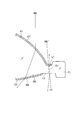
- FIG. 1 is a schematic diagram of a vapor deposition apparatus for an objective lens according to the present embodiment
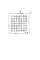
- FIG. 2 is a diagram of a holder for holding the objective lens as viewed from the direction of arrow II in FIG.
- the vapor deposition apparatus etc. for enforcing the manufacturing method of the objective lens which concerns on this embodiment first are demonstrated.
- the vapor deposition apparatus 100 supports a vapor deposition source 10 that is a film forming material source for vacuum vapor deposition, a plurality of holders 20 that hold a plurality of objective lenses, and a plurality of holders 20. Control the operation of the vapor deposition source 10, the umbrella body 30 that is rotated and inverted, the vacuum container 40 that stores the vapor deposition source 10, the umbrella body 30, the correction plate 50 that adjusts the film thickness in the meridian direction of the umbrella body 30.
- movement of the correction plate control part 94 are provided.
- the objective lens that is the target of film formation by the vapor deposition apparatus 100 is a plastic lens having a numerical aperture NA of 0.8 or more formed by injection molding using an APEL-based resin material manufactured by Mitsui Chemicals. Is used as an objective lens of an optical pickup device for BD after the film forming process.
- the vapor deposition source 10 enables vacuum deposition of various film forming materials, and includes a plurality of crucible portions 10 a and an electron gun portion 10 b arranged at the bottom of the vacuum vessel 40.
- the plurality of crucible portions 10a are supported by the turret 10d and can be switched in arrangement.
- Each crucible portion 10a contains an evaporating material for coating the surface of the objective lens, and the electron gun portion 10b is used for the evaporating material in a specific crucible portion 10a arranged at a deposition position by the turret 10d. An electron beam is incident.
- the evaporation substance in the crucible part 10a can be heated and melted by the electron beam, and the vapor EM of the evaporation substance can be injected upward from the crucible part 10a.
- the vapor deposition source 10 is operated by the vapor deposition source control unit 91.
- a plurality of film forming materials can be coated on the surface of the objective lens by sequentially moving the plurality of crucible portions 10a to the vapor deposition position, and a multilayer film can be formed by stacking different film forming materials. A coating can be formed.
- the holder 20 has a rectangular plate-like outer shape as shown in FIG. 2, and holds a number of objective lenses OL arranged two-dimensionally.
- the holder 20 is attached to the umbrella body 30 and is disposed above the vapor deposition source 10 in a state where a large number of objective lenses OL are opposed to the vapor deposition source 10.
- the holder 20 can be turned upside down or upside down together with a part of the umbrella body 30 (fan-shaped part).
- the vacuum vessel 40 supports the vapor deposition source 10 at the bottom and the umbrella 30 at the top in the internal space IS.
- a reversing mechanism 41 is provided on the wall surface of the vacuum vessel 40 in order to reverse a part of the umbrella 30.
- the vacuum vessel 40 is connected to an atmospheric pressure control unit 93 that controls the atmospheric pressure in the vacuum vessel 40. The inside of the vacuum vessel 40 is depressurized or leaked by the atmospheric pressure control unit 93.
- the correction plate 50 is for adjusting the film thickness difference in the meridian direction of the umbrella body 30.
- the correction plate 50 is disposed between the vapor deposition source 10 and the umbrella body 30.
- the posture of the correction plate 50 in the vacuum vessel 40 is controlled by the correction plate control unit 94. By appropriately raising and lowering the correction plate 50, the portion of the umbrella body 30 that is behind the correction plate 50 is not vapor-deposited.
- the control unit 90 controls operations of the vapor deposition source control unit 91, the umbrella body drive unit 92, the atmospheric pressure control unit 93, and the correction plate control unit 94.
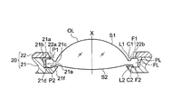
- FIG. 3 is a view of the configuration of FIG. 2 taken along the line III-III and viewed in the direction of the arrow.
- the objective lens OL is provided around the first optical surface S1, the second optical surface S2 having a smaller curvature than the first optical surface S1, and the first optical surface S1 and the second optical surface S2.
- a flange portion FL is provided around the first optical surface S1, the second optical surface S2 having a smaller curvature than the first optical surface S1, and the first optical surface S1 and the second optical surface S2.
- a flange portion FL is orthogonal to the optical axis X, respectively.
- the outer peripheral surface of the flange part FL is PL.
- the objective lens OL has a first flat surface L1 that is a mirror surface and a first inclined surface C1 between the first optical surface S1 and the first flange surface F1 of the flange portion FL so that adjacent portions are in contact with each other.
- a second flat surface L2 that is a mirror surface and a second inclined surface C2 are provided between the second optical surface S2 and the second flange surface F2 of the flange portion FL so that adjacent portions are in contact with each other. is doing.
- the surface roughness Ry of the first flat surface L1 and the second flat surface L2, which are mirror surfaces, is 0.1 ⁇ m or less, respectively.
- the first flat surface L1 and the second flat surface L2 are orthogonal to the optical axis X, respectively.
- the flange portion FL has the largest thickness between the first flange surface F1 and the second flange surface F2.
- the width of the second flat surface L2 is 0.16 to 0.45 mm.
- the first flat surface L1 is positioned closer to the second optical surface S2 in the optical axis direction than the highest vertex P1 of the first flange surface F1, and the second flat surface L2 is more than the highest vertex P2 of the second flange surface F2. Is also located on the first optical surface S1 side in the optical axis direction.
- the holder 20 constituting the shielding member includes a main body 21 and a lid portion 22 that is detachably attached to the main body 21.
- the main body 21 has a plurality of annular recesses 21a.
- the annular recess 21a includes a tapered inner peripheral surface 21b, a cylindrical inner peripheral surface 21c following the tapered inner peripheral surface 21c, an annular bottom surface 21d that intersects the cylindrical inner peripheral surface 21c and extends radially inward, and an annular bottom surface 21d.
- an annular raised portion 21e bulging annularly with a predetermined thickness on the inner side in the radial direction.
- the inner peripheral edge of the annular raised portion 21e constitutes the second opening.
- a tapered surface 21f inclined toward the second optical surface S2 is formed on the outer side in the optical axis direction of the inner peripheral edge of the annular raised portion 21e.
- the lid portion 22 is a plate having an equal thickness, and has a plurality of lid portion openings (first openings) 22a facing the annular bottom surface 21d of the main body 21, respectively.
- a tapered surface 22b inclined toward the first optical surface S1 is formed on the outer side in the optical axis direction of the inner periphery of the lid opening 22a.
- the inner peripheral edge of the lid opening 22a is located on the first flange surface F1 of the objective lens OL. However, as indicated by the dotted line, the inner peripheral edge of the lid opening 22a may be positioned on the first flat surface L1.
- the second flange surface F2 of the flange portion FL of the objective lens OL is brought into contact with the annular bottom surface 21d with the lid portion 22 removed from the main body 21.
- the outer peripheral surface PL of the flange portion FL of the objective lens OL faces or comes into contact with the cylindrical inner peripheral surface 21c.
- the objective lens OL can be held by the holder 20 by attaching the lid portion 22 to the main body 21.
- the inner peripheral edge of the annular raised portion 21e is bent toward the second flat surface L2 side of the objective lens OL, but the annular raised portion 21e has the second optical surface S2. And it is non-contact with the 2nd flat surface L2. Thereby, the damage of 2nd optical surface S2 and 2nd flat surface L2 can be suppressed.
- the annular raised portion 21e is projected in the optical axis direction, the inner peripheral edge thereof is located outside the second optical surface S2 in the direction orthogonal to the optical axis and covers 90% or more of the second flat surface L2. Yes. Thereby, the coating of the second optical surface S2 is not disturbed. Note that a part of the entire circumference of the second flat surface L2 may be covered.
- FIG. 2 An outline of a method for manufacturing an objective lens using the vapor deposition apparatus 100 of FIG. 1 will be described.
- a large number of objective lenses OL are produced by injection molding or the like.
- the individual objective lenses OL are set in the recesses of the holder 20.
- the holder 20 is attached to the umbrella body 30.
- the holders 20 are set so that the lid part 22 side of each holder 20 faces the vapor deposition source 10, but the objective lens OL does not fall from the main body 21 because of the lid part 22.
- the umbrella body 30 with the holder 20 set in this way is placed under vacuum in the vacuum vessel 40 and vapor deposition is performed by the vapor EM from the vapor deposition source 10.
- the umbrella 30 is rotated around the rotation axis OX by the rotating device 32d, thereby improving the uniformity of film formation.
- the tapered surface 22b is formed outside the inner peripheral edge of the lid portion opening 22a, a shadow is hardly generated during vapor deposition, and the coating of the first optical surface S1 is not hindered.
- the holder 20 After a certain period of time, when the film formation on the first optical surface S1 is completed, the holder 20 is inverted 180 ° and set so that the main body 21 side of the holder 20 faces the vapor deposition source 10, The same film formation is performed. Thereby, the thin film can be formed on the second optical surface S2 in a lump.
- the tapered surface 21f is formed on the outer side of the inner peripheral edge of the annular raised portion 21e, a shadow is hardly generated during vapor deposition, and the coating of the second optical surface S1 is not hindered.
- the second flat surface L2 since the second flat surface L2 is covered with the annular raised portion 21e, no coat is formed.
- the holder 20 and the like are taken out of the vacuum container 40, and the objective lens OL after vapor deposition is taken out.
- the objective lens OL is completed.
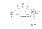
- FIG. 4 is a diagram illustrating an inspection state when the objective lens OL is assembled to the optical pickup device.
- the inspection method of the present embodiment will be described.
- the detection light DL having a wavelength of 630 to 670 nm or 380 to 420 nm is emitted from the detection device SS toward the second flat surface L2 of the objective lens OL. Since the detection light DL is reflected from the second flat surface L2 and returns to the detection device SS, the detection light DL is received by a CCD or the like. At this time, if the reflected light returns to a fixed position on the imaging surface, it can be seen that the second flat surface L2 is parallel to the optical axis of the optical pickup device.
- FIG. 5 is a schematic cross-sectional view enlarging the periphery of the flange portion of the objective lens, but the film thickness of the coat is different from the actual one.
- the antireflection coat CT is not formed on the second flat surface L2
- the intensity of the reflected light from the second flat surface L2 by the detection light DL is increased, and accurate detection is performed. be able to.
- the reflectance of the second flat surface L2 is not 100%, several percent of light may pass through the flat surface L2.
- the transmitted light DL ′ indicated by a dotted line in FIG. 5 further enters the first flat surface L1.
- the transmitted light DL ′ is reflected by the first flat surface L1 and emitted from the second flat surface L2, and the detection device SS (FIG. 4) may be detected, which may cause noise to be superimposed on the detection signal.
- the transmitted light DL ′ is transmitted through the first flat surface L1 and does not become return light, so that erroneous detection can be suppressed.
- the first flat surface L1 and the second flat surface L2 are parallel, but when the first flat surface L1 and the second flat surface L2 are non-parallel, the transmitted light DL ′ is the first light. Even if it is reflected by the flat surface L1, it is more preferable because noise can be prevented from being superimposed on the detection signal.
- the first optical surface S1 and the first flat surface L1 may be formed by an integral mold.
- the first flat surface L1 is also formed in the same manner as the first optical surface S1. It becomes a mirror surface.
- the antireflection coating CT is not formed on the first flat surface L1, and the first flat surface L1 is a mirror surface, the above-described transmitted light DL 'is more easily reflected on the first flat surface. Therefore, when the first flat surface L1 is a mirror surface, it is more effective to form the antireflection coating CT on the first flat surface L1.
- the first optical surface S1 is arranged on the side closer to the laser light source for writing (recording) or reading (reproducing) when the objective lens OL is incorporated in the optical pickup device. Further, the second optical surface S2 is disposed to face the optical information recording medium (specifically, DVD and BD) when the objective lens OL is incorporated in the optical pickup device.
- recording light WL emitted from a light source (not shown) is incident from the first optical surface S1, refracted and emitted from the second optical surface S2, and is not shown.
- the antireflection coating CT is formed on the optical surfaces S1 and S2, reflection can be suppressed and light utilization efficiency can be increased.
- the antireflection coating CT is formed on the first flat surface L1
- transmission of unnecessary light WL ′ outside the effective diameter that is not used for recording / reproducing of the optical disc is allowed to enter the first flat surface L1.
- the first optical surface S1 is a smooth mirror surface, a fine structure or a fine shape which is a diffractive structure can be provided.
- the second optical surface S2 is often a smooth mirror surface having no diffractive structure.
- FIG. 6 is a cross-sectional view of a holder 20 'that holds an objective lens OL' according to another embodiment.
- the flange portion FL ′ of the objective lens OL ′ has a straight shape (equal thickness). That is, the first flange surface F1 ′ of the flange portion FL ′ is flush with the first flat surface L1 ′, and the second flange surface F2 ′ of the flange portion FL ′ is the second flat surface L2 ′. It ’s in the same state.
- the main body 21 of the holder 20 has a bottom surface 21d ′ facing the flange portion FL ′ that is annularly raised in accordance with the objective lens OL ′, and the inner peripheral side thereof is not in contact with the second flat surface L2 ′. is there. Note that the shape and other configurations of the lid portion 22 are the same as those in the above-described embodiment.
- the numerical aperture NA of the objective lens may be 0.6 or more.
Landscapes
- Physics & Mathematics (AREA)
- Optics & Photonics (AREA)
- Optical Head (AREA)
- Moving Of The Head For Recording And Reproducing By Optical Means (AREA)
Description
本発明は、光ピックアップ装置用の対物レンズの製造方法、対物レンズ及び対物レンズの検査方法に関する。
近年、光ピックアップ装置において、光ディスクに記録された情報の再生や、光ディスクへの情報の記録のための光源として使用されるレーザ光源の短波長化が進み、例えば、青紫色半導体レーザ等、波長380~420nmのレーザ光源が実用化されている。これら青紫色レーザ光源を使用すると、DVD(デジタルバーサタイルディスク)と同じ開口数(NA)の対物レンズを使用する場合で、直径12cmの光ディスクに対して、15~20GBの情報の記録が可能となり、対物レンズの開口数NAを0.8程度にまで高めた場合には、直径12cmの光ディスクに対して、23~25GBの情報の記録が可能となる。
上述のような開口数NA0.8以上の対物レンズを使用する光ディスクの例として、BD(ブルーレイディスク)が挙げられる。光ディスクの傾き(スキュー)に起因して発生するコマ収差が増大するため、BDでは、DVD における場合よりも保護基板を薄く設計し(DVDの0.6mmに対して、0.1mm)、スキューによるコマ収差量を低減している。
しかしながら、このようにBDの保護基板厚を薄くしたとしても、開口数NA0.8以上の対物レンズを光ピックアップ装置に取り付ける際にその光軸が傾くと、それによりコマ収差が無視できなくなる恐れがある。そこで、特許文献1に示すように、対物レンズの光学面の周囲にある平坦面に対してレーザ光を照射して、その反射光を受光することで、対物レンズの姿勢を検出しながら光ピックアップ装置に取り付けることで、コマ収差を抑制するように精度良く合わせることができるようにしている。
ところで、一般的に対物レンズの光学面には、光ピックアップ装置の光源として用いる半導体レーザ光の利用効率を高めるべく、設計波長の光束の反射を防止する反射防止コートが施されている。しかしながら、この反射防止コートが、光学面の周囲に設けた平坦面に付着すると、平坦面から反射した対物レンズの傾き検査用のレーザ光の反射光強度が低下するという問題がある。より具体的には、例えば、反射防止コートの設計波長が400nm近傍であったとき、検査用のレーザ光の波長も400nm近傍であると、反射防止コートが付着した平坦面を殆ど透過してしまい、反射光の強度が著しく低下してしまい、検査が困難となる。これに対し、別な波長のレーザ光を用いることで、かかる不具合は解消できるが、検査用として用いるレーザが制限され、製造コストが増加するという問題がある。又、互換用光ピックアップ装置では、BD用の対物レンズの他に、例えば650nm前後の光束を集光するDVD用の対物レンズを併用することもあるが、かかる場合、400nm前後の波長の検査用のレーザ光の代わりに、650nm前後の波長の検査用のレーザ光を用いれば、BD用の対物レンズの検査を有効に行えるが、同じ光ピックアップ装置に取り付けるDVD用の対物レンズの検査が困難になってしまうから、異なる2つのレーザ光を検査用に準備しなくてはならず更に製造コストが増大するという問題がある。
このように検査用レーザ光の波長が限定されるという条件下では、反射防止コートが光学面の周囲に設けた平面部に付着すると、コートの設計波長と検査用レーザ光の波長とが一致したときに反射強度が小さくなってしまい、正確に対物レンズの傾き状態を検出することが困難になる恐れが強まる。これに対し特許文献1では、平面部にコートを付けないことを提案しているが、いかなる方法でコートを付けないようにするのか、具体的な方法が開示されていない。又、光軸方向両側の平面部にコートを付した場合の問題についても、何らの言及もない。
本発明は、上述の課題に鑑みてなされたものであり、低コストで精度良く光ピックアップ装置に組み付けることができる対物レンズを製造できる対物レンズの製造方法、対物レンズ及び対物レンズの検査方法を提供することを目的とする。
請求項1に記載の対物レンズの製造方法は、第1光学面と、前記第1光学面よりも曲率が小さい第2光学面と、前記第1光学面及び前記第2光学面の周囲に設けられたフランジ部とを有する光ピックアップ装置用の対物レンズの製造方法であって、
前記対物レンズは、前記第2光学面と前記フランジ部との間に第2平坦面を設けており、前記第2平坦面は鏡面であり、前記対物レンズを光ピックアップ装置に組み付ける際に、前記第2平坦面に検出光を照射して、その反射光を受光することで前記対物レンズの姿勢を検出するようになっており
前記対物レンズの成形後に、前記フランジ部側から前記第2平坦面側に延在し、且つ前記第2光学面を露出するような第2開口を有する遮蔽部材により前記第2平坦面を覆う工程と、
少なくとも前記第1光学面と前記第2光学面に、反射防止コートを施す工程とを有することを特徴とする。
前記対物レンズは、前記第2光学面と前記フランジ部との間に第2平坦面を設けており、前記第2平坦面は鏡面であり、前記対物レンズを光ピックアップ装置に組み付ける際に、前記第2平坦面に検出光を照射して、その反射光を受光することで前記対物レンズの姿勢を検出するようになっており
前記対物レンズの成形後に、前記フランジ部側から前記第2平坦面側に延在し、且つ前記第2光学面を露出するような第2開口を有する遮蔽部材により前記第2平坦面を覆う工程と、
少なくとも前記第1光学面と前記第2光学面に、反射防止コートを施す工程とを有することを特徴とする。
本発明によれば、前記対物レンズの成形後に、前記フランジ部側から前記第2平坦面側に延在し、且つ前記第2光学面を露出するような第2開口を有する遮蔽部材により前記第2平坦面を覆う工程と、少なくとも前記第1光学面と前記第2光学面に、反射防止コートを施す工程とを有するので、前記第2平坦面に反射防止コートが形成されることを抑制でき、これにより前記対物レンズを光ピックアップ装置に組み付ける際に、前記第2平坦面に検出光を照射して、その反射光を受光したときに、検出光の波長に関わらず反射光の光量が増大するから、より高精度に前記対物レンズの姿勢を検出でき、また検出光の波長制限が緩和されるため製造コストの低減を図れる。更に、前記第2平坦面が鏡面であると、前記第2平坦面の反射光の強度を向上できる。
請求項2に記載の対物レンズの製造方法は、請求項1に記載の発明において、前記フランジ部は、前記第2光学面側の第2フランジ面を有し、前記第2平坦面は、前記第2フランジ面の最頂点よりも光軸方向における前記第1光学面側に位置することを特徴とする。
例えば、製造した対物レンズを、その第2光学面を下にして載置する際に、第2光学面が載置面に直接当接して傷付かないように、フランジ部の第2光学面側の外周部を光軸方向に延長して、かかる外周部を載置面に当接させるようにすることができる。かかる場合、前記第2平坦面は、前記第2フランジ面の最頂点よりも光軸方向における前記第1光学面側に位置するようにすれば、前記対物レンズを載置した際など前記第2平坦面の傷付きを抑制できる。尚、「第2フランジ面の最頂点」とは、第2フランジ面の中で、第1光学面の面頂点に対して光軸方向に最も遠い部位をいうものとする。
請求項3に記載の対物レンズの製造方法は、請求項1又は2に記載の発明において、前記遮蔽部材の光軸方向断面において、前記第2開口の内周縁が前記第2平坦面側に向かって折れ曲がっていることを特徴とする。
例えば、前記フランジ部の前記第2光学面側の外周部を、前記第2平坦面から光軸方向に遠ざけた場合、前記遮蔽部材が前記フランジ部と干渉することを回避しなければならない一方で、前記第2平坦面の遮蔽を有効に行わなくてはならない。そこで、前記第2開口の内周縁が前記第2平坦面側に向かって折れ曲がるようにすることで、前記遮蔽部材が前記フランジ部と干渉することを抑制しつつ、前記第2平坦面の遮蔽を有効に行うことができる。
請求項4に記載の対物レンズの製造方法は、請求項1~3のいずれかに記載の発明において、前記遮蔽部材は、前記第2光学面及び前記第2平坦面に非接触であることを特徴とする。
これにより、前記第2平坦面及びその他の前記対物レンズの表面に、前記遮蔽部材が当接することによる傷付きが回避され、前記第2平坦面の反射光の強度低下を抑制できる。
請求項5に記載の対物レンズの製造方法は、請求項1~4のいずれかに記載の発明において、前記遮蔽部材は、前記第2開口の内周縁に対して光軸方向外側がテーパ形状を有していることを特徴とする。
前記第2開口の内周縁の外側をテーパ形状とすることにより、反射防止コートを付着させる際に、前記遮蔽部材が影になって前記第2光学面等に付着不足が生じないようにできる。
請求項6に記載の対物レンズの製造方法は、請求項1~5のいずれかに記載の発明において、前記第2平坦面の幅は0.16~0.45mmであることを特徴とする。
前記第2平坦面の幅が0.16mm以上であると、検出光を反射させる際に調整が困難となる恐れが回避され、一方、0.45mm以下であると、前記対物レンズの外径が大きくなり過ぎず、光ピックアップ装置の小型化に貢献する。また、第2平坦面の幅が0.2mm以上の場合、より確実に検出光を反射させることが可能となるためより好ましい。
請求項7に記載の対物レンズの製造方法は、請求項1~6のいずれかに記載の発明において、前記遮蔽部材を光軸方向に投影したときに、前記第2平坦面の90%以上を覆うことを特徴とする。
前記遮蔽部材が前記第2平坦面の90%以上を覆うようにすると、全面(100%)をきっちりと覆う場合に比べて、前記遮蔽部材の加工が容易となるし、前記遮蔽部材の先端が前記第2光学面に接触してしまうことを抑制しやすくなる。また前記遮蔽部材が前記第2平坦面の90%以上を覆うようにすることにより、前記対物レンズの姿勢検出に必要な前記第2平坦面からの反射光の強度を確保することができる。
請求項8に記載の対物レンズの製造方法は、請求項1~7のいずれかに記載の発明において、前記遮蔽部材を光軸方向に投影したときに、前記遮蔽部材の前記第2開口の内周縁は、前記第2光学面より光軸直交方向外側に位置することを特徴とする。
前記遮蔽部材の前記第2開口の内周縁を、前記第2光学面より光軸直交方向外側に位置させることで、前記第2光学面を覆うことがなく、前記第2光学面における反射防止コートの形成不足を回避できる。
請求項9に記載の対物レンズの製造方法は、請求項1~8のいずれかに記載の発明において、前記対物レンズは、前記第1光学面と前記フランジ部との間に第1平坦面を設けており、前記第1平坦面は鏡面であり、前記フランジ部は、前記第1光学面側の第1フランジ面を有し、前記遮蔽部材は、前記フランジ部側から前記第1平坦面側に延在し、且つ前記第1光学面を露出するような第1開口を有し、前記遮蔽部材を光軸方向に投影したときに、前記第1開口の内周縁が前記第1フランジ面上に位置することを特徴とする。
高開口数の対物レンズの場合には、光ピックアップ装置の光源側である第1光学面の曲率半径が小さくなり、光軸方向に出っ張っていることが多いが、かかる場合、前記第1光学面側の前記遮光部材の前記開口から前記第1光学面が突出する形になる。よって、前記遮蔽部材の前記第1開口の内周縁を光軸に近づけすぎると、前記遮蔽部材と前記第1光学面が接触してしまう恐れがある。また、前記遮蔽部材の前記第1開口の内周縁の影により、前記第1光学面の周辺部分における反射防止コートが形成不足となる恐れもある。よって、前記遮蔽部材を光軸方向に投影したときに、前記第1開口の内周縁を前記第1フランジ面上に位置させることで、前記第1光学面上に適切に反射防止コートを形成できる。
請求項10に記載の対物レンズの製造方法は、請求項1~8のいずれかに記載の発明において、前記対物レンズは、前記第1光学面と前記フランジ部との間に第1平坦面を設けており、前記第1平坦面は鏡面であり、前記フランジ部は、前記第1光学面側の第1フランジ面を有し、前記遮蔽部材は、前記フランジ部側から前記第1平坦面側に延在し、且つ前記第1光学面を露出するような第1開口を有し、前記遮蔽部材を光軸方向に投影したときに、前記第1開口の内周縁が前記第1平坦面上に位置することを特徴とする。
又、同様に、前記遮蔽部材を光軸方向に投影したときに、前記第1開口の内周縁を前記第1平坦面上に位置させることで、前記第1光学面上に適切に反射防止コートを形成できる。又、前記第1フランジ面への反射防止コートの形成を抑えることで、前記第1フランジ面を光ピックアップ装置の取り付け基準面として利用する場合に、精度的に有利である。
請求項11に記載の対物レンズの製造方法は、請求項1~10のいずれかに記載の発明において、前記対物レンズの開口数は0.6以上又は0.8以上であることを特徴とする。
本発明の対物レンズは、特にDVD用の光ピックアップ装置に用いる開口数0.6以上である対物レンズや、BD用の光ピックアップ装置に用いる開口数0.8以上である対物レンズに好適である。コマ収差は開口数の3乗に比例するため、開口数が0.6以上の対物レンズのように高い開口数を有する場合、高い組付け精度が必要となるため本発明がより有用となる。特に、BDとDVDとCDの3種類のディスクに対して互換性を有する3互換レンズの場合、コマ収差の許容が狭いため、よりいっそう高い組付け精度が必要になるため、本発明が特に有用となる。
請求項12に記載の対物レンズは、第1光学面と、前記第1光学面よりも曲率が小さい第2光学面と、前記第1光学面及び前記第2光学面の周囲に設けられたフランジ部とを有する光ピックアップ装置用の対物レンズであって、
前記対物レンズは、前記第1光学面と前記フランジ部との間に第1平坦面を設け、前記第2光学面と前記フランジ部との間に第2平坦面を設けており、前記第1平坦面と前記第2平坦面は鏡面であり、前記第1光学面と前記第2光学面と前記第1平坦面に反射防止コートを形成しているが、前記第2平坦面に反射防止コートを形成しておらず、前記対物レンズを光ピックアップ装置に組み付ける際に、前記第2平坦面に検出光を照射して、その反射光を受光することで前記対物レンズの姿勢を検出するようになっていることを特徴とする。
前記対物レンズは、前記第1光学面と前記フランジ部との間に第1平坦面を設け、前記第2光学面と前記フランジ部との間に第2平坦面を設けており、前記第1平坦面と前記第2平坦面は鏡面であり、前記第1光学面と前記第2光学面と前記第1平坦面に反射防止コートを形成しているが、前記第2平坦面に反射防止コートを形成しておらず、前記対物レンズを光ピックアップ装置に組み付ける際に、前記第2平坦面に検出光を照射して、その反射光を受光することで前記対物レンズの姿勢を検出するようになっていることを特徴とする。
本発明によれば、前記第1光学面と前記第2光学面と前記第1平坦面に反射防止コートを形成しているので、光の利用効率を高めることができると共に、前記第2平坦面に反射防止コートを形成していないので、前記対物レンズを光ピックアップ装置に組み付ける際に、前記第2平坦面に検出光を照射して、その反射光を受光したときに、検出光の波長に関わらず反射光の光量が増大するから、より高精度に前記対物レンズの姿勢を検出でき、また検出光の波長制限が緩和されるため製造コストの低減を図れる。更に、前記第2平坦面が鏡面であると、前記第2平坦面の反射光の強度を向上できる。
請求項13に記載の対物レンズは、請求項12に記載の発明において、前記フランジ部は、前記第1光学面側の第1フランジ面と、前記第2光学面側の第2フランジ面とを有し、前記第1平坦面は、前記第1フランジ面の最頂点よりも光軸方向における前記第2光学面側に位置すると共に、前記第2平坦面は、前記第2フランジ面の最頂点よりも光軸方向における前記第1光学面側に位置することを特徴とする。
例えば、製造した対物レンズを、その第2光学面を下にして載置する際に、第2光学面が載置面に直接当接して傷付かないように、フランジ部の第2光学面側の外周部を光軸方向に張り出させることで、第2フランジ面を載置面に当接させるようにすることができる。かかる場合、前記第2平坦面は、前記第2フランジ面の最頂点よりも光軸方向における前記第1光学面側に位置するようにすれば、前記対物レンズを載置した際など前記第2平坦面の傷付きを抑制できる。又、前記第1平坦面を、前記第1フランジ面の最頂点よりも光軸方向における前記第2光学面側に位置させることで、前記第1フランジ面を光ピックアップ装置の取り付け基準面として利用する場合に、干渉等が少なくなり有利である。尚、「第1フランジ面の最頂点」とは、第1フランジ面の中で、第2光学面の面頂点に対して光軸方向に最も遠い部位をいうものとする。
請求項14に記載の対物レンズは、請求項12又は13に記載の対物レンズにおいて、前記第2平坦面の幅は0.16~0.45mmであることを特徴とする。
前記第2平坦面の幅が0.16mm以上であると、検出光を反射させる際に調整が困難となる恐れが回避され、一方、0.45mm以下であると、前記対物レンズの外径が大きくなり過ぎず、光ピックアップ装置の小型化に貢献する。
請求項15に記載の対物レンズの検査方法は、第1光学面と、前記第1光学面よりも曲率が小さい第2光学面と、前記第1光学面及び前記第2光学面の周囲に設けられたフランジ部とを有する光ピックアップ装置用の対物レンズの検査方法であって、
前記対物レンズは、前記第1光学面と前記フランジ部との間に第1平坦面を設け、前記第2光学面と前記フランジ部との間に第2平坦面を設けており、前記第1平坦面と前記第2平坦面は鏡面であり、前記第1光学面と前記第2光学面と前記第1平坦面に反射防止コートを形成しているが、前記第2平坦面に反射防止コートを形成しておらず、
前記対物レンズを光ピックアップ装置に組み付ける際に、前記第2平坦面に、波長630~670nm又は380~420nmの検出光を照射して、その反射光を受光することで前記対物レンズの姿勢を検出することを特徴とする。
前記対物レンズは、前記第1光学面と前記フランジ部との間に第1平坦面を設け、前記第2光学面と前記フランジ部との間に第2平坦面を設けており、前記第1平坦面と前記第2平坦面は鏡面であり、前記第1光学面と前記第2光学面と前記第1平坦面に反射防止コートを形成しているが、前記第2平坦面に反射防止コートを形成しておらず、
前記対物レンズを光ピックアップ装置に組み付ける際に、前記第2平坦面に、波長630~670nm又は380~420nmの検出光を照射して、その反射光を受光することで前記対物レンズの姿勢を検出することを特徴とする。
本発明によれば、前記第1光学面と前記第2光学面と前記第1平坦面に反射防止コートを形成しているので、光の利用効率を高めることができると共に、前記第2平坦面に反射防止コートを形成していないので、前記対物レンズを光ピックアップ装置に組み付ける際に、前記第2平坦面に検出光を照射して、その反射光を受光したときに、検出光の波長に関わらず反射光の光量が増大するから、より高精度に前記対物レンズの姿勢を検出でき、また検出光の波長制限が緩和されるため製造コストの低減を図れる。更に、前記対物レンズに形成する反射防止コートの種類に関わらず、前記第2平坦面に検出光を照射した際に、その反射光の強度を確保できる。更に、前記第2平坦面が鏡面であると、前記第2平坦面の反射光の強度を向上できる。
本明細書において、対物レンズとは、光ピックアップ装置において光ディスクに対向する位置に配置され、光源から射出された光束を光ディスクの情報記録面上に集光する機能を有する光学系を指す。従って、本明細書中において、対物レンズの光情報記録媒体側(像側)の開口数NAとは、対物レンズの最も光情報記録媒体側に位置するレンズ面の開口数NAを指すものである。また、本明細書中では必要開口数NAは、それぞれの光情報記録媒体の規格で規定されている開口数、あるいはそれぞれの光情報記録媒体に対して、使用する光源の波長に応じ、情報の記録または再生をするために必要なスポット径を得ることができる回折限界性能の対物レンズの開口数を示すものとする。また、フランジ部とは、光学面の周囲に配置され、光ピックアップ装置に対物レンズを取り付けるために用いられる部位をいう。また、鏡面とは、面粗さRyが0.3μm以下である面をいう。なお、鏡面としては、面粗さRyが0.1μm以下であることがより好ましい。ここで、面粗さRyとは、当該面の微少凹凸における最低谷底から最大山頂までの高さのことである。また、第1平坦面と第1フランジ面とは面一でも良いし、光軸方向にシフトしていても良い。同様に、第2平坦面と第2フランジ面とは面一でも良いし、光軸方向にシフトしていても良い。
本発明によれば、低コストで精度良く光ピックアップ装置に組み付けることができる対物レンズを製造できる対物レンズの製造方法、対物レンズ及び対物レンズの検査方法を提供することができる。
以下、本発明の実施の形態を、図面を参照して説明する。図1は、本実施の形態にかかる対物レンズの蒸着装置の概略図であり、図2は、対物レンズを保持する保持具を図1の矢印II方向から見た図である。図1等を参照して、まず、本実施形態に係る対物レンズの製造方法を実施するための蒸着装置等について説明する。
図1に示すように、蒸着装置100は、真空蒸着のための成膜材料源である蒸着源10と、多数の対物レンズを保持する複数の保持具20と、複数の保持具20を支持して回転及び反転させる傘体30と、蒸着源10や傘体30等を収納する真空容器40と、傘体30の経線方向の膜厚を調節する補正板50と、蒸着源10の動作を制御する蒸着源制御部91と、傘体30を操作駆動する傘体駆動部92と、真空容器40内の気圧すなわち真空度を制御する気圧制御部93と、補正板50の配置を調整する補正板制御部94と、蒸着源制御部91、傘体駆動部92、気圧制御部93、及び補正板制御部94の動作を制御する制御部90と、を備える。なお、本蒸着装置100による成膜の対象となる対物レンズは、三井化学社製APELベースの樹脂材料を用いて射出成形により形成された開口数NA0.8以上のプラスチックレンズであり、蒸着装置100による成膜処理後においてBD用の光ピックアップ装置の対物レンズとして用いられる。
蒸着源10は、各種成膜材料の真空蒸着を可能にするものであり、真空容器40の底部に配置される複数のルツボ部分10aと電子銃部分10bとを備える。ここで、これら複数のルツボ部分10aは、ターレット10dに支持されて配置の切換が可能になっている。各ルツボ部分10aは、対物レンズの表面をコーティングするための蒸発物質を収容しており、電子銃部分10bは、ターレット10dによって蒸着位置に配置された特定のルツボ部分10a中の蒸発物質に対して電子線を入射させる。これにより、電子線でルツボ部分10a中の蒸発物質を加熱して溶かし、ルツボ部分10aから蒸発物質の蒸気EMを上方に射出させることができる。蒸着源10は、蒸着源制御部91によって動作する。なお、複数のルツボ部分10aを蒸着位置に順次移動させて蒸着を行うことにより、複数の成膜材料を対物レンズの表面上にコーティングすることができ、更に異なる成膜材料を重ねることで多層のコーティングを形成することができる。
保持具20は、図2に示すように矩形板状の外形を有し、2次元的に配置した多数の対物レンズOLを保持している。保持具20は、傘体30に取り付けられ、多数の対物レンズOLが蒸着源10に対向するような状態で蒸着源10の上方に配置される。保持具20は、傘体30の一部(扇状の部分)と共に上下又は表裏反転可能になっている。
図1に戻って真空容器40は、その内部空間ISにおいて、蒸着源10を底部に支持し、傘体30を上部に支持する。真空容器40の壁面には、傘体30の一部を反転させるために反転機構41が設けられている。なお、真空容器40には、真空容器40内の気圧を制御する気圧制御部93が接続されている。この気圧制御部93によって真空容器40内を減圧したり、リークしたりする。
補正板50は、傘体30の経線方向の膜厚差を調整するためのものである。補正板50は、蒸着源10と傘体30との間に配置されている。補正板50は、補正板制御部94によって、真空容器40内の姿勢が制御されている。補正板50を適宜上げ下ろしすることにより、傘体30において、補正板50の陰になる部分は蒸着がされないようになっている。
制御部90は、蒸着源制御部91、傘体駆動部92、気圧制御部93、及び補正板制御部94の動作を制御する。
図3は、図2の構成をIII-III線で切断して矢印方向に見た図である。図3において、対物レンズOLは、第1光学面S1と、第1光学面S1よりも曲率が小さい第2光学面S2と、第1光学面S1及び第2光学面S2の周囲に設けられたフランジ部FLとを有する。又、フランジ部FLの第1光学面側の端面である第1フランジ面F1と、フランジ部FLの第2光学面側の端面である第2フランジ面F2とは、それぞれ光軸Xに直交している。フランジ部FLの外周面をPLとする。
対物レンズOLは、第1光学面S1とフランジ部FLの第1フランジ面F1との間に、鏡面である第1平坦面L1と第1斜面C1とを、隣接部が互いに接するようにして有しており、また第2光学面S2とフランジ部FLの第2フランジ面F2との間に、鏡面である第2平坦面L2と第2斜面C2とを、隣接部が互いに接するようにして有している。鏡面である第1平坦面L1と第2平坦面L2の面粗さRyはそれぞれ0.1μm以下となっている。又、第1平坦面L1と第2平坦面L2は、それぞれ光軸Xに直交している。本実施の形態では、フランジ部FLにおいて、第1フランジ面F1と第2フランジ面F2との間が最も肉厚となっている。第2平坦面L2の幅は0.16~0.45mmである。
第1平坦面L1は、第1フランジ面F1の最頂点P1よりも光軸方向における第2光学面S2側に位置すると共に、第2平坦面L2は、第2フランジ面F2の最頂点P2よりも光軸方向における第1光学面S1側に位置している。
遮蔽部材を構成する保持具20は、本体21と、本体21に脱着可能に取り付けられた蓋部22からなる。本体21は、複数の環状の凹部21aを有している。環状の凹部21aは、テーパ状内周面21bと、これに続く円筒状内周面21cと、円筒状内周面21cに交差して半径方向内側に延在する環状底面21dと、環状底面21dの半径方向内側で所定の厚みで環状に盛り上がった環状隆起部21eとから形成されている。環状隆起部21eの内周縁が第2開口を構成する。又、環状隆起部21eの内周縁の光軸方向外側には、第2光学面S2に向かって傾いたテーパ面21fが形成されている。
蓋部22は、等厚の板状であって、本体21の環状底面21dにそれぞれ対向して、複数の蓋部開口(第1開口)22aを有している。蓋部開口22aの内周縁の光軸方向外側には、第1光学面S1に向かって傾いたテーパ面22bが形成されている。蓋部開口22aの内周縁は、対物レンズOLの第1フランジ面F1上に位置している。但し、点線で示すように、蓋部開口22aの内周縁を、第1平坦面L1上に位置させるようにしても良い。
保持具20に、成形された対物レンズOLを取り付ける場合、本体21から蓋部22を外した状態で、対物レンズOLのフランジ部FLの第2フランジ面F2を環状底面21dに当接させる。かかる状態で、対物レンズOLのフランジ部FLの外周面PLが、円筒状内周面21cに対向するか接触するようになる。更に本体21に蓋部22を取り付けることにより、対物レンズOLを保持具20に保持できる。
このとき、本体21の光軸方向断面において、環状隆起部21eの内周縁が、対物レンズOLの第2平坦面L2側に向かって折れ曲がっているが、環状隆起部21eは、第2光学面S2及び第2平坦面L2に非接触である。これにより、第2光学面S2及び第2平坦面L2の傷付きを抑制できる。又、環状隆起部21eを光軸方向に投影したときに、その内周縁は、第2光学面S2より光軸直交方向外側に位置しており、第2平坦面L2の90%以上を覆っている。これにより、第2光学面S2のコートを妨げることがない。尚、第2平坦面L2の全周の一部を覆うようにもできる。
図1の蒸着装置100を用いた対物レンズの製造方法の概要について説明する。まず、射出成形等によって対物レンズOLを多数個作製する。その後、図2に示すように、個々の対物レンズOLを保持具20の凹部内にセットする。その後、保持具20を傘体30に取り付ける。このとき、各保持具20の蓋部22側を蒸着源10に向けるようにセットするが、蓋部22があるので、対物レンズOLは本体21から落下することがない。
更に、このように保持具20をセットした傘体30を、真空容器40内で真空下におき、蒸着源10からの蒸気EMによって蒸着が行われる。この際、傘体30が回転装置32dによって回転軸OXのまわりに回転することで、成膜の均一性を高める。このとき、蓋部開口22aの内周縁の外側にテーパ面22bが形成されているので、蒸着時に影が生じにくく第1光学面S1のコートを妨げない。
一定時間後、第1光学面S1上への薄膜の成膜が完了した段階で、保持具20を180°反転させ、保持具20の本体21側を蒸着源10に向けるようにセットして、同様の成膜を行う。これにより、第2光学面S2上への薄膜の成膜も一括して行うことができる。
このとき、環状隆起部21eの内周縁の外側にテーパ面21fが形成されているので、蒸着時に影が生じにくく第2光学面S1のコートを妨げない。しかしながら、第2平坦面L2は環状隆起部21eにより覆われているため、コートの形成がされない。
このとき、環状隆起部21eの内周縁の外側にテーパ面21fが形成されているので、蒸着時に影が生じにくく第2光学面S1のコートを妨げない。しかしながら、第2平坦面L2は環状隆起部21eにより覆われているため、コートの形成がされない。
その後、真空容器40内から保持具20等を搬出し、蒸着後の対物レンズOLを取り出す。以上により、対物レンズOLが完成する。
図4は、対物レンズOLを光ピックアップ装置に組み付ける際の検査状態を示す図である。図4を参照して、本実施の検査方法を説明する。まずフランジ部FLの第1フランジ面F1及び外周面PLを光ピックアップ装置のレンズホルダHLDに当接させて、対物レンズOLを保持する。かかる状態で、検出装置SSから対物レンズOLの第2平坦面L2に向かって、波長630~670nm又は380~420nmの検出光DLを出射する。
かかる検出光DLは、第2平坦面L2から反射して再び検出装置SSに戻るので、これをCCDなどにより受光する。このとき、反射光が撮像面の定位置に戻れば、第2平坦面L2が光ピックアップ装置の光軸と平行であることが分かる。
かかる検出光DLは、第2平坦面L2から反射して再び検出装置SSに戻るので、これをCCDなどにより受光する。このとき、反射光が撮像面の定位置に戻れば、第2平坦面L2が光ピックアップ装置の光軸と平行であることが分かる。
図5は、対物レンズのフランジ部周辺を拡大した断面模式図であるが、コートの膜厚は実際と異なる。本実施の形態によれば、第2平坦面L2に反射防止コートCTが形成されていないので、検出光DLによる第2平坦面L2からの反射光の強度が増大し、精度の良い検出を行うことができる。しかるに、第2平坦面L2の反射率は100%ではないため、数%の光が平坦面L2を透過する場合がある。かかる場合、図5において点線で示す透過光DL’は、更に第1平坦面L1に入射する。ここで、第1平坦面L1に反射防止コートCTが形成されていないとした場合、透過光DL’が第1平坦面L1で反射して第2平坦面L2から出射し、検出装置SS(図4)で検出される恐れがあり、それにより検出信号にノイズが重畳する恐れがある。これに対し第1平坦面L1に反射防止コートCTが形成されていれば、透過光DL’が第1平坦面L1を透過してしまい戻り光とならないため、誤検出を抑制できる。なお、本実施の形態では第1平坦面L1と第2平坦面L2を平行としたが、第1平坦面L1と第2平坦面L2とが非平行である場合、透過光DL’が第1平坦面L1で反射したとしても、検出信号にノイズが重畳しないようにできるためより好ましい。
また、レンズ成形上の観点から、第1光学面S1と第1平坦面L1を一体の金型で成形することがあるが、その場合、第1光学面S1と同様に第1平坦面L1も鏡面となってしまう。第1平坦面L1に反射防止コートCTが形成されておらず、第1平坦面L1が鏡面である場合、上述した透過光DL’がよりいっそう第1平坦面で反射しやすくなってしまう。ゆえに、第1平坦面L1が鏡面である場合には、第1平坦面L1に反射防止コートCTを形成することがより有効となる。
第1光学面S1は、対物レンズOLを光ピックアップ装置に組み込んだとき、書き込み(記録)又は読み取り(再生)用のレーザ光源により近い側に配置される。また、第2光学面S2は、対物レンズOLを光ピックアップ装置に組み込んだとき、光情報記録媒体(具体的にはDVD及びBD)に対向して配置される。光ピックアップ装置の動作時には、図5に示すように、不図示の光源から出射された記録光WLが、第1光学面S1から入射し、屈折して第2光学面S2から出射して不図示の光情報記録媒体に集光するが、光学面S1,S2に反射防止コートCTが形成されていることで、反射を抑制して光の利用効率を高めることができる。一方、第1平坦面L1に反射防止コートCTが形成されていれば、光ディスクの記録/再生に用いない有効径外の不要光WL’が第1平坦面L1に入射した場合、その透過を許容することで、エラー信号を招く検出器側への反射を抑制できる。
第1光学面S1は、滑らかな鏡面となっているが、回折構造である微細構造又は微細形状を設けることもできる。一方、第2光学面S2は、回折構造等を有しない滑らかな鏡面となることが多い。対物レンズOLの光学面S1,S2に反射防止コートを施すことで、透過率は6%程度上昇する。
第1光学面S1は、滑らかな鏡面となっているが、回折構造である微細構造又は微細形状を設けることもできる。一方、第2光学面S2は、回折構造等を有しない滑らかな鏡面となることが多い。対物レンズOLの光学面S1,S2に反射防止コートを施すことで、透過率は6%程度上昇する。
図6は、別な実施の形態にかかる対物レンズOL’を保持する保持具20’の断面図である。本実施の形態では、対物レンズOL’のフランジ部FL’が、ストレート形状(等厚)となっている。つまり、フランジ部FL’の第1フランジ面F1’が、第1平坦面L1’と面一の状態であり、またフランジ部FL’の第2フランジ面F2’が、第2平坦面L2’と面一の状態である。保持具20の本体21は、対物レンズOL’に合わせて、フランジ部FL’に対向する底面21d’が環状に盛り上がっており、その内周側は第2平坦面L2’と非接触の状態にある。尚、蓋部22の形状及びその他の構成は、上述した実施の形態と同様である。
本発明は、明細書に記載の実施例に限定されるものではなく、他の実施例・変形例を含むことは、本明細書に記載された実施例や技術思想から本分野の当業者にとって明らかである。明細書の記載及び実施例は、あくまでも例証を目的としており、本発明の範囲は後述するクレームによって示されている。例えば対物レンズの開口数NAは0.6以上でよい。
10 蒸着源
10a ルツボ部分
10b 電子銃部分
10d ターレット
20 保持具
21 本体
21a 凹部
21b テーパ状内周面
21c 円筒状内周面
21d 底面
21d’ 環状底面
21e 環状隆起部
21f テーパ面
22 蓋部
22a 蓋部開口
22b テーパ面
30 傘体
32d 回転装置
40 真空容器
41 反転機構
50 補正板
90 制御部
91 蒸着源制御部
92 傘体駆動部
93 気圧制御部
94 補正板制御部
100 蒸着装置
C1 第1斜面
C2 第2斜面
DL 検出光
DL’ 透過光
EM 蒸気
F1、F1’ 第1フランジ面
F2、F2’ 第2フランジ面
FL、FL’ フランジ部
HLD レンズホルダ
IS 内部空間
L1、L1’ 第1平坦面
L2、L2’ 第2平坦面
OL、OL’ 対物レンズ
OX 回転軸
PL 外周面
S1 第1光学面
S2 第2光学面
SS 検出装置
CT 反射防止コート
WL 記録光
WL’ 不要光
HLD レンズホルダ
10a ルツボ部分
10b 電子銃部分
10d ターレット
20 保持具
21 本体
21a 凹部
21b テーパ状内周面
21c 円筒状内周面
21d 底面
21d’ 環状底面
21e 環状隆起部
21f テーパ面
22 蓋部
22a 蓋部開口
22b テーパ面
30 傘体
32d 回転装置
40 真空容器
41 反転機構
50 補正板
90 制御部
91 蒸着源制御部
92 傘体駆動部
93 気圧制御部
94 補正板制御部
100 蒸着装置
C1 第1斜面
C2 第2斜面
DL 検出光
DL’ 透過光
EM 蒸気
F1、F1’ 第1フランジ面
F2、F2’ 第2フランジ面
FL、FL’ フランジ部
HLD レンズホルダ
IS 内部空間
L1、L1’ 第1平坦面
L2、L2’ 第2平坦面
OL、OL’ 対物レンズ
OX 回転軸
PL 外周面
S1 第1光学面
S2 第2光学面
SS 検出装置
CT 反射防止コート
WL 記録光
WL’ 不要光
HLD レンズホルダ
Claims (15)
- 第1光学面と、前記第1光学面よりも曲率が小さい第2光学面と、前記第1光学面及び前記第2光学面の周囲に設けられたフランジ部と、を有する光ピックアップ装置用の対物レンズの製造方法であって、
前記対物レンズは、前記第2光学面と前記フランジ部との間に第2平坦面を設けており、前記第2平坦面は鏡面であり、前記対物レンズを光ピックアップ装置に組み付ける際に、前記第2平坦面に検出光を照射して、その反射光を受光することで前記対物レンズの姿勢を検出するようになっており
前記対物レンズの成形後に、前記フランジ部側から前記第2平坦面側に延在し、且つ前記第2光学面を露出するような第2開口を有する遮蔽部材により前記第2平坦面を覆う工程と、
少なくとも前記第1光学面と前記第2光学面に、反射防止コートを施す工程と、を有することを特徴とする対物レンズの製造方法。 - 前記フランジ部は、前記第2光学面側の第2フランジ面を有し、前記第2平坦面は、前記第2フランジ面の最頂点よりも光軸方向における前記第1光学面側に位置することを特徴とする請求項1に記載の対物レンズの製造方法。
- 前記遮蔽部材の光軸方向断面において、前記第2開口の内周縁が前記第2平坦面側に向かって折れ曲がっていることを特徴とする請求項1又は2に記載の対物レンズの製造方法。
- 前記遮蔽部材は、前記第2光学面及び前記第2平坦面に非接触であることを特徴とする請求項1~3のいずれか1項に記載の対物レンズの製造方法。
- 前記遮蔽部材は、前記第2開口の内周縁に対して光軸方向外側がテーパ形状を有していることを特徴とする請求項1~4のいずれか1項に記載の対物レンズの製造方法。
- 前記第2平坦面の幅は0.1~0.45mmであることを特徴とする請求項1~5のいずれか1項に記載の対物レンズの製造方法。
- 前記遮蔽部材を光軸方向に投影したときに、前記第2平坦面の90%以上を覆うことを特徴とする請求項1~6のいずれか1項に記載の対物レンズの製造方法。
- 前記遮蔽部材を光軸方向に投影したときに、前記遮蔽部材の前記第2開口の内周縁は、前記第2光学面より光軸直交方向外側に位置することを特徴とする請求項1~7のいずれか1項に記載の対物レンズの製造方法。
- 前記対物レンズは、前記第1光学面と前記フランジ部との間に第1平坦面を設けており、前記第1平坦面は鏡面であり、前記フランジ部は、前記第1光学面側の第1フランジ面を有し、前記遮蔽部材は、前記フランジ部側から前記第1平坦面側に延在し、且つ前記第1光学面を露出するような第1開口を有し、前記遮蔽部材を光軸方向に投影したときに、前記第1開口の内周縁が前記第1フランジ面上に位置することを特徴とする請求項1~8のいずれか1項に記載の対物レンズの製造方法。
- 前記対物レンズは、前記第1光学面と前記フランジ部との間に第1平坦面を設けており、前記第1平坦面は鏡面であり、前記フランジ部は、前記第1光学面側の第1フランジ面を有し、前記遮蔽部材は、前記フランジ部側から前記第1平坦面側に延在し、且つ前記第1光学面を露出するような第1開口を有し、前記遮蔽部材を光軸方向に投影したときに、前記第1開口の内周縁が前記第1平坦面上に位置することを特徴とする請求項1~8のいずれか1項に記載の対物レンズの製造方法。
- 前記対物レンズの開口数は0.6以上又は0.8以上であることを特徴とする請求項1~10のいずれか1項に記載の対物レンズの製造方法。
- 第1光学面と、前記第1光学面よりも曲率が小さい第2光学面と、前記第1光学面及び前記第2光学面の周囲に設けられたフランジ部とを有する光ピックアップ装置用の対物レンズであって、
前記対物レンズは、前記第1光学面と前記フランジ部との間に第1平坦面を設け、前記第2光学面と前記フランジ部との間に第2平坦面を設けており、前記第1平坦面と前記第2平坦面は鏡面であり、前記第1光学面と前記第2光学面と前記第1平坦面に反射防止コートを形成しているが、前記第2平坦面に反射防止コートを形成しておらず、前記対物レンズを光ピックアップ装置に組み付ける際に、前記第2平坦面に検出光を照射して、その反射光を受光することで前記対物レンズの姿勢を検出するようになっていることを特徴とする対物レンズ。 - 前記フランジ部は、前記第1光学面側の第1フランジ面と、前記第2光学面側の第2フランジ面とを有し、前記第1平坦面は、前記第1フランジ面の最頂点よりも光軸方向における前記第2光学面側に位置すると共に、前記第2平坦面は、前記第2フランジ面の最頂点よりも光軸方向における前記第1光学面側に位置することを特徴とする請求項12に記載の対物レンズ。
- 前記第2平坦面の幅は0.16~0.45mmであることを特徴とする請求項12又は13に記載の対物レンズ。
- 第1光学面と、前記第1光学面よりも曲率が小さい第2光学面と、前記第1光学面及び前記第2光学面の周囲に設けられたフランジ部とを有する光ピックアップ装置用の対物レンズの検査方法であって、
前記対物レンズは、前記第1光学面と前記フランジ部との間に第1平坦面を設け、前記第2光学面と前記フランジ部との間に第2平坦面を設けており、前記第1平坦面と前記第2平坦面は鏡面であり、前記第1光学面と前記第2光学面と前記第1平坦面に反射防止コートを形成しているが、前記第2平坦面に反射防止コートを形成しておらず、
前記対物レンズを光ピックアップ装置に組み付ける際に、前記第2平坦面に、波長630~670nm又は380~420nmの検出光を照射して、その反射光を受光することで前記対物レンズの姿勢を検出することを特徴とする対物レンズの検査方法。
Priority Applications (1)
| Application Number | Priority Date | Filing Date | Title |
|---|---|---|---|
| CN201380007448.XA CN104106114A (zh) | 2012-01-31 | 2013-01-26 | 光拾取装置用物镜的制造方法、物镜及物镜的检查方法 |
Applications Claiming Priority (2)
| Application Number | Priority Date | Filing Date | Title |
|---|---|---|---|
| JP2012017516 | 2012-01-31 | ||
| JP2012-017516 | 2012-01-31 |
Publications (1)
| Publication Number | Publication Date |
|---|---|
| WO2013115113A1 true WO2013115113A1 (ja) | 2013-08-08 |
Family
ID=48905153
Family Applications (1)
| Application Number | Title | Priority Date | Filing Date |
|---|---|---|---|
| PCT/JP2013/051674 Ceased WO2013115113A1 (ja) | 2012-01-31 | 2013-01-26 | 光ピックアップ装置用の対物レンズの製造方法、対物レンズ及び対物レンズの検査方法 |
Country Status (3)
| Country | Link |
|---|---|
| JP (1) | JPWO2013115113A1 (ja) |
| CN (1) | CN104106114A (ja) |
| WO (1) | WO2013115113A1 (ja) |
Families Citing this family (2)
| Publication number | Priority date | Publication date | Assignee | Title |
|---|---|---|---|---|
| JP2018004912A (ja) * | 2016-06-30 | 2018-01-11 | キヤノン株式会社 | 光学部品、光学部品の製造方法およびカメラ |
| JP6365803B1 (ja) * | 2017-09-12 | 2018-08-01 | 三菱電機株式会社 | 光モジュールの製造方法 |
Citations (5)
| Publication number | Priority date | Publication date | Assignee | Title |
|---|---|---|---|---|
| JP2001348080A (ja) * | 2000-04-04 | 2001-12-18 | Nissin Kohki Co Ltd | 製品収納容器 |
| JP2003121604A (ja) * | 2001-10-12 | 2003-04-23 | Konica Corp | 光学レンズ部品 |
| JP2003294915A (ja) * | 2002-04-04 | 2003-10-15 | Sankyo Seiki Mfg Co Ltd | 光ヘッド装置用対物レンズおよびその傾角調整方法 |
| JP2009104732A (ja) * | 2007-10-25 | 2009-05-14 | Hitachi Maxell Ltd | 光ピックアップレンズ |
| JP2011216163A (ja) * | 2010-04-01 | 2011-10-27 | Sanyo Electric Co Ltd | 対物レンズ |
Family Cites Families (1)
| Publication number | Priority date | Publication date | Assignee | Title |
|---|---|---|---|---|
| DE69812643T2 (de) * | 1997-08-19 | 2004-04-01 | Kabushiki Kaisha Kenwood | Optisches abtastgerät, halter, und verfahren zur herstellung eines optischen abtastgerätes |
-
2013
- 2013-01-26 CN CN201380007448.XA patent/CN104106114A/zh active Pending
- 2013-01-26 WO PCT/JP2013/051674 patent/WO2013115113A1/ja not_active Ceased
- 2013-01-26 JP JP2013556379A patent/JPWO2013115113A1/ja active Pending
Patent Citations (5)
| Publication number | Priority date | Publication date | Assignee | Title |
|---|---|---|---|---|
| JP2001348080A (ja) * | 2000-04-04 | 2001-12-18 | Nissin Kohki Co Ltd | 製品収納容器 |
| JP2003121604A (ja) * | 2001-10-12 | 2003-04-23 | Konica Corp | 光学レンズ部品 |
| JP2003294915A (ja) * | 2002-04-04 | 2003-10-15 | Sankyo Seiki Mfg Co Ltd | 光ヘッド装置用対物レンズおよびその傾角調整方法 |
| JP2009104732A (ja) * | 2007-10-25 | 2009-05-14 | Hitachi Maxell Ltd | 光ピックアップレンズ |
| JP2011216163A (ja) * | 2010-04-01 | 2011-10-27 | Sanyo Electric Co Ltd | 対物レンズ |
Also Published As
| Publication number | Publication date |
|---|---|
| JPWO2013115113A1 (ja) | 2015-05-11 |
| CN104106114A (zh) | 2014-10-15 |
Similar Documents
| Publication | Publication Date | Title |
|---|---|---|
| JP5049149B2 (ja) | 光ピックアップ用対物レンズ | |
| JP4259067B2 (ja) | 光ピックアップ装置の対物光学素子、光ピックアップ装置及び光情報記録再生装置 | |
| KR20090042150A (ko) | 광픽업 렌즈 | |
| US8259541B2 (en) | Optical recording/reproduction method, optical recording/reproduction device, program, and optical recording medium | |
| KR20080071096A (ko) | 광 픽업용 대물 렌즈 | |
| JP2010157315A (ja) | 非球面レンズ及びそれを対物レンズとして採用した光ピックアップ | |
| WO2013115113A1 (ja) | 光ピックアップ装置用の対物レンズの製造方法、対物レンズ及び対物レンズの検査方法 | |
| WO2010084784A1 (ja) | 光学ヘッド及び光情報装置 | |
| WO2011099329A1 (ja) | 光ピックアップ装置の対物レンズ及び光ピックアップ装置 | |
| JP2009123316A (ja) | 対物レンズ、これを備えた光ピックアップ装置、およびこの光ピックアップ装置を搭載した光記録媒体記録および/または再生装置 | |
| TWI383389B (zh) | 光學拾取頭及資訊處理裝置 | |
| US20070025208A1 (en) | Lens position control method, lens position control apparatus, cutting method, and cutting apparatus | |
| KR20070116547A (ko) | 광 디스크 장치 | |
| US8897106B2 (en) | Objective lens for optical pickup and optical pickup apparatus having the same | |
| CN1423253A (zh) | 光盘和记录/再现设备 | |
| JP5170588B2 (ja) | 光ピックアップ装置の対物光学素子、光ピックアップ装置及び光情報記録再生装置 | |
| US20060067204A1 (en) | Objective lens and scanning device using such an objective lens | |
| JP4108436B2 (ja) | 光ディスク | |
| JP5725033B2 (ja) | 光ピックアップ装置用の対物レンズ及び光ピックアップ装置 | |
| JP5122506B2 (ja) | 対物レンズ群と光ピックアップ装置 | |
| JP4897405B2 (ja) | 光ピックアップおよび光情報処理装置 | |
| JP2009217907A (ja) | 光ピックアップ光学系及び対物レンズ | |
| WO2007080925A1 (ja) | 光ピックアップ装置および当該光ピックアップ装置を備えた情報処理装置 | |
| JP2006048878A (ja) | 光学記録媒体の製造方法 | |
| US20060137818A1 (en) | Laminating apparatus and method |
Legal Events
| Date | Code | Title | Description |
|---|---|---|---|
| 121 | Ep: the epo has been informed by wipo that ep was designated in this application |
Ref document number: 13742976 Country of ref document: EP Kind code of ref document: A1 |
|
| ENP | Entry into the national phase |
Ref document number: 2013556379 Country of ref document: JP Kind code of ref document: A |
|
| NENP | Non-entry into the national phase |
Ref country code: DE |
|
| 122 | Ep: pct application non-entry in european phase |
Ref document number: 13742976 Country of ref document: EP Kind code of ref document: A1 |