WO2013114669A1 - 充電量検出装置 - Google Patents
充電量検出装置 Download PDFInfo
- Publication number
- WO2013114669A1 WO2013114669A1 PCT/JP2012/074722 JP2012074722W WO2013114669A1 WO 2013114669 A1 WO2013114669 A1 WO 2013114669A1 JP 2012074722 W JP2012074722 W JP 2012074722W WO 2013114669 A1 WO2013114669 A1 WO 2013114669A1
- Authority
- WO
- WIPO (PCT)
- Prior art keywords
- battery
- charge amount
- complex impedance
- tilt angle
- relationship
- Prior art date
Links
Images


Classifications
-
- G—PHYSICS
- G01—MEASURING; TESTING
- G01R—MEASURING ELECTRIC VARIABLES; MEASURING MAGNETIC VARIABLES
- G01R31/00—Arrangements for testing electric properties; Arrangements for locating electric faults; Arrangements for electrical testing characterised by what is being tested not provided for elsewhere
- G01R31/36—Arrangements for testing, measuring or monitoring the electrical condition of accumulators or electric batteries, e.g. capacity or state of charge [SoC]
- G01R31/3644—Constructional arrangements
- G01R31/3648—Constructional arrangements comprising digital calculation means, e.g. for performing an algorithm
-
- G—PHYSICS
- G01—MEASURING; TESTING
- G01R—MEASURING ELECTRIC VARIABLES; MEASURING MAGNETIC VARIABLES
- G01R31/00—Arrangements for testing electric properties; Arrangements for locating electric faults; Arrangements for electrical testing characterised by what is being tested not provided for elsewhere
- G01R31/36—Arrangements for testing, measuring or monitoring the electrical condition of accumulators or electric batteries, e.g. capacity or state of charge [SoC]
- G01R31/382—Arrangements for monitoring battery or accumulator variables, e.g. SoC
-
- G—PHYSICS
- G01—MEASURING; TESTING
- G01R—MEASURING ELECTRIC VARIABLES; MEASURING MAGNETIC VARIABLES
- G01R31/00—Arrangements for testing electric properties; Arrangements for locating electric faults; Arrangements for electrical testing characterised by what is being tested not provided for elsewhere
- G01R31/36—Arrangements for testing, measuring or monitoring the electrical condition of accumulators or electric batteries, e.g. capacity or state of charge [SoC]
- G01R31/389—Measuring internal impedance, internal conductance or related variables
-
- G—PHYSICS
- G01—MEASURING; TESTING
- G01R—MEASURING ELECTRIC VARIABLES; MEASURING MAGNETIC VARIABLES
- G01R31/00—Arrangements for testing electric properties; Arrangements for locating electric faults; Arrangements for electrical testing characterised by what is being tested not provided for elsewhere
- G01R31/36—Arrangements for testing, measuring or monitoring the electrical condition of accumulators or electric batteries, e.g. capacity or state of charge [SoC]
- G01R31/392—Determining battery ageing or deterioration, e.g. state of health
-
- H—ELECTRICITY
- H01—ELECTRIC ELEMENTS
- H01M—PROCESSES OR MEANS, e.g. BATTERIES, FOR THE DIRECT CONVERSION OF CHEMICAL ENERGY INTO ELECTRICAL ENERGY
- H01M10/00—Secondary cells; Manufacture thereof
- H01M10/42—Methods or arrangements for servicing or maintenance of secondary cells or secondary half-cells
- H01M10/48—Accumulators combined with arrangements for measuring, testing or indicating the condition of cells, e.g. the level or density of the electrolyte
-
- H—ELECTRICITY
- H02—GENERATION; CONVERSION OR DISTRIBUTION OF ELECTRIC POWER
- H02J—CIRCUIT ARRANGEMENTS OR SYSTEMS FOR SUPPLYING OR DISTRIBUTING ELECTRIC POWER; SYSTEMS FOR STORING ELECTRIC ENERGY
- H02J7/00—Circuit arrangements for charging or depolarising batteries or for supplying loads from batteries
- H02J7/007—Regulation of charging or discharging current or voltage
- H02J7/00712—Regulation of charging or discharging current or voltage the cycle being controlled or terminated in response to electric parameters
- H02J7/00714—Regulation of charging or discharging current or voltage the cycle being controlled or terminated in response to electric parameters in response to battery charging or discharging current
- H02J7/00716—Regulation of charging or discharging current or voltage the cycle being controlled or terminated in response to electric parameters in response to battery charging or discharging current in response to integrated charge or discharge current
-
- H—ELECTRICITY
- H02—GENERATION; CONVERSION OR DISTRIBUTION OF ELECTRIC POWER
- H02J—CIRCUIT ARRANGEMENTS OR SYSTEMS FOR SUPPLYING OR DISTRIBUTING ELECTRIC POWER; SYSTEMS FOR STORING ELECTRIC ENERGY
- H02J7/00—Circuit arrangements for charging or depolarising batteries or for supplying loads from batteries
- H02J7/02—Circuit arrangements for charging or depolarising batteries or for supplying loads from batteries for charging batteries from ac mains by converters
- H02J7/04—Regulation of charging current or voltage
-
- G—PHYSICS
- G01—MEASURING; TESTING
- G01R—MEASURING ELECTRIC VARIABLES; MEASURING MAGNETIC VARIABLES
- G01R31/00—Arrangements for testing electric properties; Arrangements for locating electric faults; Arrangements for electrical testing characterised by what is being tested not provided for elsewhere
- G01R31/36—Arrangements for testing, measuring or monitoring the electrical condition of accumulators or electric batteries, e.g. capacity or state of charge [SoC]
- G01R31/367—Software therefor, e.g. for battery testing using modelling or look-up tables
-
- Y—GENERAL TAGGING OF NEW TECHNOLOGICAL DEVELOPMENTS; GENERAL TAGGING OF CROSS-SECTIONAL TECHNOLOGIES SPANNING OVER SEVERAL SECTIONS OF THE IPC; TECHNICAL SUBJECTS COVERED BY FORMER USPC CROSS-REFERENCE ART COLLECTIONS [XRACs] AND DIGESTS
- Y02—TECHNOLOGIES OR APPLICATIONS FOR MITIGATION OR ADAPTATION AGAINST CLIMATE CHANGE
- Y02E—REDUCTION OF GREENHOUSE GAS [GHG] EMISSIONS, RELATED TO ENERGY GENERATION, TRANSMISSION OR DISTRIBUTION
- Y02E60/00—Enabling technologies; Technologies with a potential or indirect contribution to GHG emissions mitigation
- Y02E60/10—Energy storage using batteries
Definitions
- the present invention relates to a battery charge amount detection device, and more particularly to a technique for performing complex impedance analysis of the charge amount of a secondary battery.
- Patent Document 1 in a method of measuring a discharge state of a battery having an internal impedance, a first internal impedance of the battery is measured at a first frequency, and a second internal impedance of the battery is measured at a second frequency. It is described that a difference between the first internal impedance and the second internal impedance is obtained, and a declination or argument of the difference between the internal impedances is obtained to express a declination or argument representing a state of discharge of the battery. . Moreover, it is described that the lower one of the first frequency and the second frequency is between 0.1 and 10 Hz.
- an AC voltage is applied to the secondary battery to detect an electric quantity related to the impedance of the secondary battery or an electric quantity related to the maximum output density, and the secondary battery is based on the electric quantity. It is described that the performance is determined. Further, it is described that the electric quantity is an AC impedance-related electric quantity related to an AC impedance component composed of a component that varies depending on the frequency of the AC voltage in the impedance of the secondary battery. Also, an AC voltage having a large number of frequency values within a predetermined frequency band is applied to the secondary battery, and the real axis component value and the imaginary axis component value of the impedance of the secondary battery are obtained for each frequency value.
- the electric quantity related to the impedance is calculated from the value and the imaginary axis component value. Further, it is described that the AC impedance component is calculated based on the diameter of the circular arc locus of the impedance in a two-dimensional plane having the real axis component value and the imaginary axis component value as axes.
- the above document describes that the state of the battery is detected by impedance, but the battery state is detected from the impedance of the so-called charge transfer resistance region, and the battery state is always sufficiently detected. I could not say. For example, in a nickel metal hydride battery, even if the SOC changes, there is no change in the impedance of the charge transfer resistance region. Therefore, the SOC cannot be estimated from the impedance of the charge transfer resistance region.
- An object of the present invention is to provide an apparatus that can detect the amount of charge of a battery with high accuracy by complex impedance analysis of the battery.
- the present invention is an apparatus for detecting the amount of charge of a battery, and includes two measuring means for measuring a complex impedance in the diffusion region of the battery, and two different frequencies in the diffusion region of the battery measured by the measurement unit.
- the detector includes a detecting unit that calculates the inclination angle of the straight line or the approximate line connecting the complex impedances, and a storage unit that stores in advance the relationship between the inclination angle and the charge amount, and the detecting unit calculates the calculated inclination angle.
- the charge amount of the battery is detected using the relationship between the tilt angle and the charge amount stored in the storage means.
- the present invention is an apparatus for detecting the amount of charge of a battery, the frequency of which is the same as the frequency of a reference complex impedance that is a complex impedance in a diffusion region of a base battery serving as a reference when comparing the batteries.
- Measuring means for measuring the complex impedance in the diffusion region of the battery detecting means for detecting the distance between the reference complex impedance and the complex impedance measured by the measuring means, and the relationship between the distance and the charge amount in advance.
- the detection unit in addition to the distance between the reference complex impedance and the complex impedance measured by the measurement unit, includes the reference complex impedance and the complex impedance measured by the measurement unit. Detect the tilt angle of the straight line connecting
- the storage means further stores in advance the relationship between the tilt angle and the charge amount, and the detection means includes the calculated distance and the distance stored in the storage means.
- the charge amount of the battery is detected using the calculated tilt angle and the relationship between the tilt angle stored in the storage means and the charge amount.
- the charge amount of the battery to be detected can be detected with high accuracy by the complex impedance analysis of the battery. Therefore, for example, when the battery mounted on the vehicle is accurately controlled or the battery is reused, the reuse efficiency can be improved by applying the present invention.
- the secondary battery charge amount detection device In the secondary battery charge amount detection device according to the present embodiment, the secondary battery charge amount is detected by paying attention to the behavior in a specific frequency region out of the complex impedance behavior of the secondary battery.
- a nickel-metal hydride battery Ni-MH battery
- the present invention is not limited to this, and for example, other alkaline batteries and non-aqueous batteries such as lithium batteries can also be used. Is available.
- FIG. 1 shows a complex impedance curve obtained by connecting respective complex impedances of an equivalent circuit when an alternating voltage is applied to a battery in a discharged state while changing the frequency.
- Equivalent circuits and complex impedances are well known and are described in, for example, Patent Document 2 described above.
- the impedance of a battery is an equivalent circuit in which a DC impedance component and an AC impedance component are connected in series.
- the AC impedance component is equivalent to a parallel circuit of a resistor and a capacitor.
- Zreal (Zr) is the real axis component of the complex impedance
- Zimg (Zi) is the imaginary axis component of the complex impedance.
- FIG. 1 is a two-dimensional representation of the real and imaginary axis components of the complex impedance of a battery, with the paired data of the real and imaginary axis components, the horizontal axis representing the real axis component Zr and the vertical axis representing the imaginary axis component Zi.
- the circle mark indicates 0.1 Hz
- the diamond mark indicates 1 Hz
- the triangle mark indicates 10 Hz
- the square mark indicates 100 Hz.
- the region having a low frequency is a region composed of complex impedance in which material diffusion is involved, and in this embodiment is referred to as a region composed of complex impedance in the diffusion region.
- the complex impedance curve shown in FIG. 1 is composed of a curve portion (charge transfer resistance region) indicating a high-frequency side arc and a substantially linear portion, but at a frequency lower than the inflection point. This part (substantially linear part) is a region constituted by complex impedance in the diffusion region.
- the present invention detects the amount of charge (SOC) of the battery using the complex impedance of the diffusion region described above.
- SOC charge amount
- the charge amount (SOC) of the battery 10 is detected using a slope angle of a straight line connecting two complex impedances having different frequencies in the diffusion region (hereinafter referred to as a slope angle of the complex impedance in the diffusion region). That is, as shown in FIG. 1, the inclination angle of the complex impedance in the diffusion region changes according to the capacities of the positive electrode and the negative electrode, that is, there is a correlation between the SOC and the inclination angle. By utilizing this, it is possible to evaluate the SOC of the battery 10 from the inclination angle of the complex impedance in the diffusion region. In the present embodiment, such SOC detection will be described.
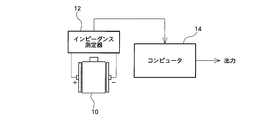
- FIG. 2 shows a configuration diagram of the charge amount detection device of the present embodiment.
- the charge amount detection device includes an impedance measuring device (or impedance analyzer) 12 that is a measuring unit that measures the complex impedance of the battery 10 by applying an AC voltage to the battery 10 to be detected, and the battery measured by the impedance analyzer 12. Data of two complex impedances having different frequencies in the ten diffusion regions are supplied, and a CPU of a computer 14 serving as detection means for calculating the inclination angle of a straight line connecting these complex impedance data is provided.
- the computer 14 further includes a memory that is a storage unit that stores in advance the relationship between the tilt angle and the charge amount.
- FIG. 3 shows a processing flowchart of the present embodiment.
- a measurement electrode is connected to the battery 10, an AC voltage is applied, and the complex impedance of the battery 10 is measured by the impedance measuring device 12 (S201).
- the frequency of the alternating voltage to be applied to the battery 10 is at least two frequencies in the diffusion region, for example, 0.1 Hz and 0.5 Hz, but is not limited thereto.
- the computer 14 calculates the inclination of the diffusion region, that is, the inclination angle of the graph (Nyquist plot) in FIG. 4 and the like using the complex impedance data at the two frequencies obtained by the impedance measuring device 12 (S202). .
- the inclination angle may be either a mathematical or graphic (geometric) method.
- the complex impedance at a relatively high frequency is a first complex impedance and the complex impedance at a relatively low frequency is a second complex impedance, the first and second complex impedances are connected. Calculate the inclination angle of the straight line.
- the computer 14 compares the relationship between the SOC and the tilt angle stored in advance in the memory with the calculated tilt angle (S203), and determines the SOC of the battery 10 according to the comparison result. (S204).
- the relationship between the SOC and the tilt angle the SOC and the tilt angle of a plurality of batteries are measured in advance, and the relationship between the two is defined as a function or a table and stored in a memory.
- FIG. 4 shows the complex impedance in the diffusion region of various SOC batteries.
- reference numeral 300 denotes a complex impedance of a nickel hydride battery of SOC 10%
- reference numeral 400 denotes a complex impedance of a nickel hydride battery of SOC 20%
- reference numeral 500 denotes a complex impedance of a nickel hydride battery of SOC 60%.
- the inclination angle of the diffusion region in each SOC is not the same, and the inclination angle tends to decrease as the SOC increases. That is, assuming that the inclination angles of SOC 10%, 20%, and 60% are ⁇ 1, ⁇ 2, and ⁇ 3, respectively, the relationship is ⁇ 1> ⁇ 2> ⁇ 3.
- FIG. 5 shows the relationship between the SOC and tilt angle of a nickel metal hydride battery.
- the horizontal axis represents the charge amount (SOC) (%), and the vertical axis represents the inclination angle (deg) of the diffusion region.
- SOC charge amount
- deg inclination angle
- the relationship between the SOC and the tilt angle shown in FIG. 5 is defined as a function or table and stored in a memory, and the SOC is uniquely detected from the tilt angle of the battery 10 obtained by calculation. .
- the SOC error relative to the tilt angle is relatively small compared to when the SOC is large. Therefore, when the SOC is small, the SOC can be detected from the tilt angle with high accuracy. Is possible. If it is known that the SOC of the battery 10 is relatively large (for example, 50% or more), the SOC of the battery 10 is detected by another method, and the SOC of the battery 10 is known to be relatively small (for example, 10% or less). If so, it is possible to selectively use the SOC of the battery 10 with high accuracy by the method of the present embodiment.
- the reference complex impedance which is a complex impedance in the diffusion region of the base battery that serves as a reference when comparing the batteries 10, and the complex impedance in the diffusion region of the battery 10 having the same frequency as the frequency of the reference complex impedance.
- the distance of the complex impedance in the diffusion region of the battery 10 having the same frequency as the reference complex impedance and the reference complex impedance Used to detect the SOC of the battery 10.
- an impedance measuring instrument (or impedance analyzer) 12 that is a measuring means measures the complex impedance in the diffusion region of the battery 10 having the same frequency as that of the reference complex impedance.
- the CPU of the computer 14 serving as the detection means calculates a tilt angle of a straight line connecting the reference complex impedance and the complex impedance measured by the measurement means.
- a memory that is a storage unit stores in advance the relationship between the distance and the charge amount, and the relationship between the tilt angle and the charge amount.
- the CPU of the computer 14 serving as the detection unit stores the relationship between the calculated distance, the distance stored in the storage unit, and the charge amount, the calculated tilt angle, and the storage. The charge amount of the battery 10 is detected using the relationship between the tilt angle stored in the means and the charge amount.
- FIG. 6 shows a processing flowchart of the present embodiment.
- a measurement electrode is connected to the battery 10 to be detected, an AC voltage is applied, and the complex impedance of the battery 10 is measured by the impedance measuring instrument 12 (S401).
- the frequency of the alternating voltage to be applied to the battery 10 is one frequency in the diffusion region, for example, 0.1 Hz, but is not limited thereto.
- the computer 14 reads, from the memory, the reference complex impedance having the same frequency as the measured frequency among the reference complex impedances which are complex impedances in the diffusion region of the base battery which becomes the reference when comparing the batteries 10.
- the base battery refers to, for example, the battery 10 in the initial state or a battery that is different from the battery 10 but is known to be normal.
- the inclination angle of the straight line connecting the complex impedance obtained in S401 and the reference complex impedance read from the memory and the distance between them are calculated (S402).
- the tilt angle and distance may be either mathematical or graphic (geometric).
- the complex impedance of the base battery is known SOC, for example 20% complex impedance.
- the computer 14 compares the tendency of the distance and inclination angle stored in advance in the memory with the inclination angle and distance obtained by the calculation (S403), and determines the SOC of the battery 10 according to the comparison result. Determine (S404).
- FIG. 7 schematically shows the processing of this embodiment.
- point 40 is the complex impedance at a certain frequency in the diffusion region of the base battery, for example, 0.1 Hz
- point 60 is the complex impedance at the same frequency in the SOC 30% of the battery
- point 61 is the battery 10. It is the complex impedance at the same frequency in SOC 60%.
- the SOC of the battery 10 changes from the SOC of the base battery
- the points 60 and 61 change accordingly from the point 40, and the distance and the tilt angle change accordingly.
- the tilt angle is in the range of approximately 0 deg to 90 deg, or 180 deg to 270 deg.
- the distance changes as the SOC changes. Therefore, if it is known that the distance and the tilt angle, in particular, the battery 10 is normal, the SOC can be detected using the distance.
- FIG. 8 shows an example of the relationship between battery SOC and distance. There is a correlation between the SOC and the distance. The distance increases as the SOC increases from 0% to 60%, and the distance decreases as the SOC increases from 60% to 100%. Show the trend.
- FIG. 9 shows an example of the relationship between the SOC of the battery and the tilt angle. In the case of a normal battery, if the SOC is increased with respect to the base battery, the tilt angle is in the range of about 30 deg to 45 deg. Even if the tilt angle changes, the SOC does not change much.
- the computer 14 shows the relationship between the SOC and distance shown in FIG. 8 and the SOC and inclination angle shown in FIG. Can be used to detect the SOC of the battery 10.
- the tilt angle in the case of a normal battery, the tilt angle is in the range of about 30 deg to 45 deg. However, since the tilt angle slightly varies depending on the SOC value, it is possible to estimate the SOC from the tilt angle. is there.
- the relationship between the SOC and the tilt angle in FIG. 5 is different from the relationship between the SOC and the tilt angle in FIG. 8, but this is the slope between the complex impedances at two different frequencies in the diffusion region. Note that the latter is based on the fact that the latter tilt angle represents the tilt angle between complex impedances at the same frequency in the diffusion region. In this sense, “inclination angle” in the first embodiment is “inclination angle between two different frequencies”, and “inclination angle” in the second embodiment is “inclination angle between the same frequencies”.
- the charge amount of the battery 10 can be detected using the slope angles of the complex impedances at two different frequencies in the diffusion region. Moreover, the charge amount of the battery 10 can be detected using the inclination angle and distance of the complex impedance at the same frequency in the diffusion region.
- Frequency condition two different frequencies in the diffusion region
- Detection item Inclination angle
- Detection state Charge amount
- Second embodiment Frequency condition one frequency in the diffusion region
- Reference complex impedance (first complex impedance) initial state of the battery, or complex impedance of another normal battery (stored in memory in advance)
- Detection item Inclination angle and distance
- Detection state Charge amount
- the reference complex impedance in the first embodiment is a complex impedance at one of the two frequencies (for example, the higher one), and is measured by the impedance measuring instrument 12.
- the complex impedance at a certain frequency in the diffusion region is known in advance, this is stored in advance as a reference complex impedance in the memory, and the impedance measuring device 12 can measure the complex impedance at other frequencies.
- the impedance measuring device 12 does not necessarily need to measure the complex impedance at two different frequencies.
- the reference complex impedance is stored in the memory in advance prior to the measurement of the battery 10, it is not necessary to measure with the impedance measuring instrument 12.
- the inclination angle of a straight line connecting two complex impedances having different frequencies in the diffusion region of the battery 10 is calculated, but three or different frequencies in the diffusion region of the battery 10 are calculated.
- the inclination angle of a straight line or an approximate straight line connecting the above complex impedances may be calculated.
- the complex impedance in the diffusion region of the battery includes the Warburg impedance and the transmission model impedance.
- the charge amount is detected using the Warburg impedance, but the charge amount may be detected using the impedance of the transmission model.
- the Warburg impedance is a known impedance related to hydrogen diffusion, for example, Kuriyama, N., et al .: J Alloy & Compd., 202 (1993), 183 Zhang, W., et al .: Electrochem. Soc. The 185 th Meet., (1994), abstr.No.593 Etc. are disclosed.
- Figure 10 shows the Warburg impedance and the transmission model impedance, respectively.
- region A is Warburg impedance
- region B is the impedance of the transmission model.
- the inclination angle of a straight line connecting the impedances of two transmission models having different frequencies is calculated, and the battery is obtained using the obtained inclination angle and the relationship between the inclination angle and the charge amount. Detect the amount of charge.
- the complex impedance is Nyquist plotted to calculate the tilt angle.
- a Bode diagram may be used.
- the alternating voltage is applied to the measurement of complex impedance, what is necessary is just an alternating current signal, for example, you may apply an alternating current.
Landscapes
- Physics & Mathematics (AREA)
- General Physics & Mathematics (AREA)
- Engineering & Computer Science (AREA)
- Power Engineering (AREA)
- Manufacturing & Machinery (AREA)
- Chemical & Material Sciences (AREA)
- Chemical Kinetics & Catalysis (AREA)
- Electrochemistry (AREA)
- General Chemical & Material Sciences (AREA)
- Secondary Cells (AREA)
- Tests Of Electric Status Of Batteries (AREA)
- Charge And Discharge Circuits For Batteries Or The Like (AREA)
Abstract
Description
前記記憶手段は、距離と充電量との関係に加え、さらに、傾き角度と充電量との関係を予め記憶し、前記検出手段は、算出された距離と、前記記憶手段に記憶された距離と充電量との関係に加え、算出された傾き角度と、前記記憶手段に記憶された傾き角度と充電量との関係を用いて前記電池の充電量を検出することを特徴とする。
まず、本実施形態における基本原理について説明する。本実施形態における二次電池の充電量検出装置では、二次電池の複素インピーダンスの挙動のうち、特定の周波数領域における挙動に着目して二次電池の充電量を検出するものである。なお、以下の説明では二次電池としてニッケル水素電池(Ni-MH電池)を例にとり説明するが、これに限定されるものではなく、例えば他のアルカリ電池やリチウム電池等の非水系電池にも利用可能である。
Z=Vac/Iac=Zreal+jZimg
として得られる。Zreal(Zr)は複素インピーダンスの実軸成分、Zimg(Zi)は複素インピーダンスの虚軸成分である。図1は、電池の複素インピーダンスの実軸成分及び虚軸成分を求め、実軸成分と虚軸成分のペアデータを、横軸を実軸成分Zr、縦軸を虚軸成分Ziとする二次元平面にプロットしたものである(ナイキストプロット:横軸では右側をプラス側、左側をマイナス側とし、縦軸では上側をマイナス側、下側をプラス側としている:他のナイキストプロットも同じ)。放電状態の電池に対して、(正極容量(Ah),負極容量(Ah))=(5.54,8.5)、(4.54,7.5)、(3.54,6.5)、(2.54,5.5)、(1.54,4.5)、(0.54,3.5)、(0,2.96)のそれぞれの容量において周波数を変化させたときの複素インピーダンスの実軸成分、虚軸成分である。図において、0.1Hz、1Hz、10Hz、100Hzの点を明示的に示している。具体的には、丸印が0.1Hz、菱形印が1Hz、三角印が10Hz、四角印が100Hzを示す。周波数が低い領域は、物質拡散の関与した複素インピーダンスで構成された領域であり、本実施形態においては、拡散領域における複素インピーダンスで構成された領域と称する。具体的には、図1で示す複素インピーダンス曲線は、高周波数側の円弧を示す曲線部分(電荷移動抵抗領域)と、略直線状の部分から構成されているが、その変曲点より低周波数の部分(略直線状の部分)が拡散領域における複素インピーダンスで構成される領域である。
本実施形態では、拡散領域における周波数の異なる2つの複素インピーダンスを結んだ直線の傾き角度(以下、拡散領域における複素インピーダンスの傾き角度という)を用いて電池10の充電量(SOC)を検出する。すなわち、図1に示されるように、拡散領域における複素インピーダンスの傾き角度は、正極及び負極の容量に応じて変化する、つまりSOCと傾き角度との間には相関関係があるため、この事実を利用して、拡散領域における複素インピーダンスの傾き角度から電池10のSOCを評価することが可能である。本実施形態では、このようなSOCの検出について説明する。
本実施形態では、電池10を比較する際に基準となるベース電池の拡散領域内の複素インピーダンスである基準複素インピーダンスと、基準複素インピーダンスの周波数と同一の周波数の電池10の拡散領域内の複素インピーダンスとを結んだ直線の傾き角度(以下、拡散領域における複素インピーダンスの傾き角度という)および、基準複素インピーダンスと、基準複素インピーダンスの周波数と同一の周波数の電池10の拡散領域内の複素インピーダンスの距離を用いて電池10のSOCを検出する。なお、第1実施形態の測定手段の代わりに、測定手段であるインピーダンス測定器(あるいはインピーダンスアナライザ)12は基準複素インピーダンスの周波数と同一の周波数の電池10の拡散領域内の複素インピーダンスを測定する。また、第1実施形態の検出手段の代わりに、検出手段であるコンピュータ14のCPUは、基準複素インピーダンスと測定手段で測定した複素インピーダンスを結んだ直線の傾き角度を算出する。さらに、第1実施形態の記憶手段の代わりに、記憶手段であるメモリは、距離と充電量との関係と、傾き角度と充電量との関係を予め記憶する。そして、第1実施形態の検出手段の代わりに、検出手段であるコンピュータ14のCPUは、算出された距離と記憶手段に記憶された距離と充電量との関係と、算出された傾き角度と記憶手段に記憶された傾き角度と充電量との関係を用いて、電池10の充電量を検出する。
周波数条件:拡散領域内の異なる2つの周波数
基準複素インピーダンス(第1複素インピーダンス):2つの周波数のうちのいずれか(例えば高い方の周波数)での複素インピーダンス(インピーダンス測定器12で測定してもよく、予めメモリに記憶してもよい)
検出項目:傾き角度
検出状態:充電量
周波数条件:拡散領域内の一つの周波数
基準複素インピーダンス(第1複素インピーダンス):電池の初期状態、あるいは正常である他の電池の複素インピーダンス(予めメモリに記憶)
検出項目:傾き角度及び距離
検出状態:充電量
Kuriyama, N., et al. : J Alloy & Compd., 202 (1993), 183
Zhang, W., et al. : Electrochem. Soc. the 185th Meet., (1994), abstr. No.593
等に開示されている。
Claims (6)
- 電池の充電量を検出する装置であって、
前記電池の拡散領域内の複素インピーダンスを測定する測定手段と、
前記測定手段で測定した前記電池の拡散領域内の周波数の異なる2つ以上の前記複素インピーダンスを結んだ直線または近似直線の傾き角度を算出する検出手段と、
傾き角度と充電量との関係を予め記憶する記憶手段と、
を備え、前記検出手段は、算出された傾き角度と、前記記憶手段に記憶された傾き角度と充電量との関係を用いて前記電池の充電量を検出することを特徴とする充電量検出装置。 - 請求項1記載の充電量検出装置であって、
前記検出手段は、実軸成分及び虚軸成分を軸とする二次元平面を用いて、周波数の異なる2つ以上の前記複素インピーダンスを結んだ直線または近似直線の傾き角度を算出することを特徴とする充電量検出装置。 - 電池の充電量を検出する装置であって、
前記電池を比較する際に基準となるベース電池の拡散領域内の複素インピーダンスである基準複素インピーダンスの周波数と同一の周波数の前記電池の拡散領域内の複素インピーダンスを測定する測定手段と、
前記基準複素インピーダンスと前記測定手段で測定した前記複素インピーダンスとの間の距離を検出する検出手段と、
距離と充電量との関係を予め記憶する記憶手段と、
を備え、前記検出手段は、算出された距離と、前記記憶手段に記憶された距離と充電量との関係を用いて前記電池の充電量を検出することを特徴とする充電量検出装置。 - 請求項3記載の充電量検出装置であって、
前記検出手段は、実軸成分及び虚軸成分を軸とする二次元平面を用いて、前記基準複素インピーダンスと前記測定手段で測定した前記複素インピーダンスとの間の距離を検出することを特徴とする充電量検出装置。 - 請求項3,4のいずれかに記載の充電量検出装置であって、
前記検出手段は、前記基準複素インピーダンスと前記測定手段で測定した前記複素インピーダンスとの間の距離に加え、前記基準複素インピーダンスと前記測定手段で測定した複素インピーダンスとを結んだ直線の傾き角度を検出し、
前記記憶手段は、距離と充電量との関係に加え、さらに、傾き角度と充電量との関係を予め記憶し、
前記検出手段は、算出された距離と、前記記憶手段に記憶された距離と充電量との関係に加え、算出された傾き角度と、前記記憶手段に記憶された傾き角度と充電量との関係を用いて前記電池の充電量を検出することを特徴とする充電量検出装置。 - 請求項5記載の充電量検出装置であって、
前記検出手段は、実軸成分及び虚軸成分を軸とする二次元平面を用いて、前記基準複素インピーダンスと、前記測定手段で測定した前記複素インピーダンスとを結んだ直線の傾き角度を算出することを特徴とする充電量検出装置。
Priority Applications (3)
| Application Number | Priority Date | Filing Date | Title |
|---|---|---|---|
| EP12867453.8A EP2811310B1 (en) | 2012-01-31 | 2012-09-26 | State of charge detection device |
| US14/343,743 US10429444B2 (en) | 2012-01-31 | 2012-09-26 | State of charge detection device |
| JP2013556195A JP6027030B2 (ja) | 2012-01-31 | 2012-09-26 | 充電量検出装置 |
Applications Claiming Priority (2)
| Application Number | Priority Date | Filing Date | Title |
|---|---|---|---|
| JP2012-018746 | 2012-01-31 | ||
| JP2012018746 | 2012-01-31 |
Publications (1)
| Publication Number | Publication Date |
|---|---|
| WO2013114669A1 true WO2013114669A1 (ja) | 2013-08-08 |
Family
ID=48904737
Family Applications (1)
| Application Number | Title | Priority Date | Filing Date |
|---|---|---|---|
| PCT/JP2012/074722 WO2013114669A1 (ja) | 2012-01-31 | 2012-09-26 | 充電量検出装置 |
Country Status (4)
| Country | Link |
|---|---|
| US (1) | US10429444B2 (ja) |
| EP (1) | EP2811310B1 (ja) |
| JP (2) | JP6027030B2 (ja) |
| WO (1) | WO2013114669A1 (ja) |
Cited By (9)
| Publication number | Priority date | Publication date | Assignee | Title |
|---|---|---|---|---|
| JP2018091716A (ja) * | 2016-12-02 | 2018-06-14 | トヨタ自動車株式会社 | 電池状態推定装置 |
| JP2018128383A (ja) * | 2017-02-09 | 2018-08-16 | トヨタ自動車株式会社 | 電池状態推定装置 |
| CN108572323A (zh) * | 2017-03-10 | 2018-09-25 | 丰田自动车株式会社 | 电池状态推测装置 |
| EP3457151A1 (en) | 2017-08-24 | 2019-03-20 | Toyota Jidosha Kabushiki Kaisha | Impedance estimating apparatus |
| JP2019049479A (ja) * | 2017-09-11 | 2019-03-28 | プライムアースEvエナジー株式会社 | 二次電池状態判定方法及び二次電池状態判定装置 |
| JP2019117180A (ja) * | 2017-12-27 | 2019-07-18 | プライムアースEvエナジー株式会社 | 電池状態推定装置及び電池状態推定方法 |
| CN110416635A (zh) * | 2018-04-26 | 2019-11-05 | 丰田自动车株式会社 | 电池信息处理系统、电池组、电池模块的特性评价方法以及电池组的制造方法 |
| JP2020021592A (ja) * | 2018-07-31 | 2020-02-06 | トヨタ自動車株式会社 | 電池情報処理システム、二次電池の容量推定方法、ならびに、組電池、および、その組電池の製造方法 |
| US11121386B2 (en) | 2017-08-24 | 2021-09-14 | Toyota Jidosha Kabushiki Kaisha | Temperature estimating apparatus |
Families Citing this family (7)
| Publication number | Priority date | Publication date | Assignee | Title |
|---|---|---|---|---|
| WO2013115038A1 (ja) | 2012-01-31 | 2013-08-08 | プライムアースEvエナジー株式会社 | 電池状態検出装置 |
| JP6672112B2 (ja) * | 2016-09-06 | 2020-03-25 | プライムアースEvエナジー株式会社 | 電池容量測定装置及び電池容量測定方法 |
| GB2547502B (en) * | 2016-11-10 | 2018-05-02 | Tanktwo Oy | Detection of false reporting in a smart battery system |
| JP6575548B2 (ja) | 2017-03-22 | 2019-09-18 | トヨタ自動車株式会社 | 電池状態推定装置 |
| EP3505946B1 (en) * | 2017-12-27 | 2023-03-15 | Primearth EV Energy Co., Ltd. | Battery state estimation device and battery state estimation method |
| EP3812780B1 (en) * | 2019-10-23 | 2022-09-28 | Novum engineerING GmbH | Estimating a battery state from gradients of electrical impedance measurements |
| KR20220068806A (ko) * | 2020-11-19 | 2022-05-26 | 주식회사 엘지에너지솔루션 | 배터리 진단 장치 및 방법 |
Citations (4)
| Publication number | Priority date | Publication date | Assignee | Title |
|---|---|---|---|---|
| JPS60144675A (ja) | 1983-12-12 | 1985-07-31 | アスラブ・ソシエテ・アノニム | 電池の放電状態の測定方法及び装置 |
| JPH05135806A (ja) * | 1991-05-31 | 1993-06-01 | American Teleph & Telegr Co <Att> | 蓄電池の残存容量の決定方法 |
| JP2000299137A (ja) | 1998-08-10 | 2000-10-24 | Toyota Motor Corp | 二次電池の状態判定方法及び状態判定装置、並びに二次電池の再生方法 |
| JP2011158444A (ja) * | 2010-02-04 | 2011-08-18 | Gs Yuasa Corp | 二次電池の残存容量検出方法および装置 |
Family Cites Families (10)
| Publication number | Priority date | Publication date | Assignee | Title |
|---|---|---|---|---|
| US5717336A (en) * | 1992-12-24 | 1998-02-10 | Elcorp Pty. Ltd. | Method and apparatus for determining the charge condition of an electrochemical cell |
| JPH0843506A (ja) | 1994-08-02 | 1996-02-16 | Nippon Telegr & Teleph Corp <Ntt> | ニッケル系電池の劣化状態検知方法 |
| JP3402167B2 (ja) | 1996-12-17 | 2003-04-28 | 松下電器産業株式会社 | 電池の状態解析装置 |
| JP4030217B2 (ja) | 1999-03-12 | 2008-01-09 | トヨタ自動車株式会社 | 組電池の異常判定装置および異常判定方法 |
| FR2813124B1 (fr) | 2000-08-17 | 2003-01-17 | Oldham France Sa | Procede de test d'une batterie au plomb en vue de sa charge dans des conditions optimales |
| DE10345057B4 (de) * | 2003-09-26 | 2005-09-15 | Rheinisch-Westfälisch-Technische Hochschule Aachen | Verfahren und Vorrichtung zur Bestimmung des Ladezustandes einer Batterie |
| KR100823507B1 (ko) * | 2006-08-29 | 2008-04-21 | 삼성에스디아이 주식회사 | 배터리 관리 시스템 및 그 구동방법 |
| DE102009000337A1 (de) | 2009-01-21 | 2010-07-22 | Robert Bosch Gmbh | Verfahren zur Bestimmung eines Alterungszustandes einer Batteriezelle mittels Impedanzspektroskopie |
| US20120001925A1 (en) * | 2010-06-30 | 2012-01-05 | Ati Technologies, Ulc | Dynamic Feedback Load Balancing |
| WO2013115038A1 (ja) | 2012-01-31 | 2013-08-08 | プライムアースEvエナジー株式会社 | 電池状態検出装置 |
-
2012
- 2012-09-26 US US14/343,743 patent/US10429444B2/en active Active
- 2012-09-26 JP JP2013556195A patent/JP6027030B2/ja active Active
- 2012-09-26 EP EP12867453.8A patent/EP2811310B1/en active Active
- 2012-09-26 WO PCT/JP2012/074722 patent/WO2013114669A1/ja active Application Filing
-
2016
- 2016-04-13 JP JP2016080567A patent/JP6114433B2/ja active Active
Patent Citations (4)
| Publication number | Priority date | Publication date | Assignee | Title |
|---|---|---|---|---|
| JPS60144675A (ja) | 1983-12-12 | 1985-07-31 | アスラブ・ソシエテ・アノニム | 電池の放電状態の測定方法及び装置 |
| JPH05135806A (ja) * | 1991-05-31 | 1993-06-01 | American Teleph & Telegr Co <Att> | 蓄電池の残存容量の決定方法 |
| JP2000299137A (ja) | 1998-08-10 | 2000-10-24 | Toyota Motor Corp | 二次電池の状態判定方法及び状態判定装置、並びに二次電池の再生方法 |
| JP2011158444A (ja) * | 2010-02-04 | 2011-08-18 | Gs Yuasa Corp | 二次電池の残存容量検出方法および装置 |
Non-Patent Citations (3)
| Title |
|---|
| KURIYAMA, N. ET AL., J ALLOY & COMPD., vol. 202, 1993, pages 183 |
| See also references of EP2811310A4 |
| ZHANG, W. ET AL., ELECTROCHEM. SOC. THE 185TH MEET., 1994 |
Cited By (17)
| Publication number | Priority date | Publication date | Assignee | Title |
|---|---|---|---|---|
| US10718817B2 (en) | 2016-12-02 | 2020-07-21 | Toyota Jidosha Kabushiki Kaisha | Battery state estimating apparatus |
| JP2018091716A (ja) * | 2016-12-02 | 2018-06-14 | トヨタ自動車株式会社 | 電池状態推定装置 |
| US10507734B2 (en) | 2017-02-09 | 2019-12-17 | Toyota Jidosha Kabushiki Kaisha | Battery state estimating apparatus |
| JP2018128383A (ja) * | 2017-02-09 | 2018-08-16 | トヨタ自動車株式会社 | 電池状態推定装置 |
| CN108414942A (zh) * | 2017-02-09 | 2018-08-17 | 丰田自动车株式会社 | 电池状态推定装置 |
| JP2018151194A (ja) * | 2017-03-10 | 2018-09-27 | トヨタ自動車株式会社 | 電池状態推定装置 |
| US10656216B2 (en) | 2017-03-10 | 2020-05-19 | Toyota Jidosha Kabushiki Kaisha | Battery state estimating apparatus |
| CN108572323A (zh) * | 2017-03-10 | 2018-09-25 | 丰田自动车株式会社 | 电池状态推测装置 |
| CN108572323B (zh) * | 2017-03-10 | 2020-11-20 | 丰田自动车株式会社 | 电池状态推测装置 |
| EP3457151A1 (en) | 2017-08-24 | 2019-03-20 | Toyota Jidosha Kabushiki Kaisha | Impedance estimating apparatus |
| US11121386B2 (en) | 2017-08-24 | 2021-09-14 | Toyota Jidosha Kabushiki Kaisha | Temperature estimating apparatus |
| JP2019049479A (ja) * | 2017-09-11 | 2019-03-28 | プライムアースEvエナジー株式会社 | 二次電池状態判定方法及び二次電池状態判定装置 |
| JP2019117180A (ja) * | 2017-12-27 | 2019-07-18 | プライムアースEvエナジー株式会社 | 電池状態推定装置及び電池状態推定方法 |
| JP7025287B2 (ja) | 2017-12-27 | 2022-02-24 | プライムアースEvエナジー株式会社 | 電池状態推定装置及び電池状態推定方法 |
| CN110416635A (zh) * | 2018-04-26 | 2019-11-05 | 丰田自动车株式会社 | 电池信息处理系统、电池组、电池模块的特性评价方法以及电池组的制造方法 |
| CN110416635B (zh) * | 2018-04-26 | 2022-09-20 | 丰田自动车株式会社 | 电池信息处理系统、电池组、电池模块的特性评价方法以及电池组的制造方法 |
| JP2020021592A (ja) * | 2018-07-31 | 2020-02-06 | トヨタ自動車株式会社 | 電池情報処理システム、二次電池の容量推定方法、ならびに、組電池、および、その組電池の製造方法 |
Also Published As
| Publication number | Publication date |
|---|---|
| US10429444B2 (en) | 2019-10-01 |
| JP6027030B2 (ja) | 2016-11-16 |
| JP2016166880A (ja) | 2016-09-15 |
| EP2811310A1 (en) | 2014-12-10 |
| EP2811310A4 (en) | 2015-04-22 |
| JPWO2013114669A1 (ja) | 2015-05-11 |
| JP6114433B2 (ja) | 2017-04-12 |
| US20140229130A1 (en) | 2014-08-14 |
| EP2811310B1 (en) | 2019-05-15 |
Similar Documents
| Publication | Publication Date | Title |
|---|---|---|
| JP6114433B2 (ja) | 充電量検出装置 | |
| JP5873113B2 (ja) | 電池状態検出装置 | |
| TWI235514B (en) | Detecting method for detecting internal information of a rechargeable battery, detecting apparatus for detecting internal information of a rechargeable battery, apparatus in which said detecting method is applied, apparatus including said detecting a | |
| US9588185B2 (en) | Method and apparatus for detecting cell deterioration in an electrochemical cell or battery | |
| JP6151163B2 (ja) | 電池状態算出装置および電池状態算出方法 | |
| EP3021127A1 (en) | Method for estimating state of electricity storage device | |
| JP6300000B2 (ja) | 充電状態推定装置、充電状態推定方法 | |
| TW202127052A (zh) | 電池健全性之評估方法及系統 | |
| JP2020060581A (ja) | 蓄電素子管理装置、socのリセット方法、蓄電素子モジュール、蓄電素子管理プログラム及び移動体 | |
| WO2014167920A1 (ja) | 電池状態判定装置 | |
| JP2011133443A (ja) | 診断装置、電池パック及び電池価値指標の製造方法 | |
| WO2016009757A1 (ja) | 電池状態検知装置、二次電池システム、プログラム製品、電池状態検知方法 | |
| JP2017009577A (ja) | 状態推定装置及び状態推定方法 | |
| JP6382663B2 (ja) | 電池状態判定方法及び電池状態判定装置 | |
| JP6749080B2 (ja) | 蓄電システム、二次電池の制御システム及び二次電池の制御方法 | |
| JP2008107168A (ja) | 電池特性の検出方法及び電池特性の検出装置 | |
| JP4954791B2 (ja) | 蓄電デバイスの電圧予測方法 | |
| JP2010160055A (ja) | 電池検査方法 | |
| JP2023515593A (ja) | バッテリー診断装置、方法及びシステム | |
| JP3654469B2 (ja) | 二次電池の残存容量検出方法 | |
| JP6747382B2 (ja) | リチウムイオン電池の状態推定装置および状態推定方法 | |
| JP7194385B2 (ja) | 組電池の評価方法および電池システム | |
| JP2022080182A (ja) | 電池モジュール | |
| JP6074759B2 (ja) | 鉛蓄電池の劣化判断方法及び劣化判断装置 |
Legal Events
| Date | Code | Title | Description |
|---|---|---|---|
| 121 | Ep: the epo has been informed by wipo that ep was designated in this application |
Ref document number: 12867453 Country of ref document: EP Kind code of ref document: A1 |
|
| WWE | Wipo information: entry into national phase |
Ref document number: 2012867453 Country of ref document: EP |
|
| WWE | Wipo information: entry into national phase |
Ref document number: 14343743 Country of ref document: US |
|
| ENP | Entry into the national phase |
Ref document number: 2013556195 Country of ref document: JP Kind code of ref document: A |
|
| NENP | Non-entry into the national phase |
Ref country code: DE |