WO2013111705A1 - 回路圧制御装置、この回路圧制御装置を用いた油圧制御回路、及び建設機械の油圧制御回路 - Google Patents
回路圧制御装置、この回路圧制御装置を用いた油圧制御回路、及び建設機械の油圧制御回路 Download PDFInfo
- Publication number
- WO2013111705A1 WO2013111705A1 PCT/JP2013/051091 JP2013051091W WO2013111705A1 WO 2013111705 A1 WO2013111705 A1 WO 2013111705A1 JP 2013051091 W JP2013051091 W JP 2013051091W WO 2013111705 A1 WO2013111705 A1 WO 2013111705A1
- Authority
- WO
- WIPO (PCT)
- Prior art keywords
- circuit
- pressure control
- pressure
- control device
- actuator
- Prior art date
Links
Images
Classifications
-
- F—MECHANICAL ENGINEERING; LIGHTING; HEATING; WEAPONS; BLASTING
- F15—FLUID-PRESSURE ACTUATORS; HYDRAULICS OR PNEUMATICS IN GENERAL
- F15B—SYSTEMS ACTING BY MEANS OF FLUIDS IN GENERAL; FLUID-PRESSURE ACTUATORS, e.g. SERVOMOTORS; DETAILS OF FLUID-PRESSURE SYSTEMS, NOT OTHERWISE PROVIDED FOR
- F15B13/00—Details of servomotor systems ; Valves for servomotor systems
- F15B13/10—Special arrangements for operating the actuated device with or without using fluid pressure, e.g. for emergency use
-
- F—MECHANICAL ENGINEERING; LIGHTING; HEATING; WEAPONS; BLASTING
- F15—FLUID-PRESSURE ACTUATORS; HYDRAULICS OR PNEUMATICS IN GENERAL
- F15B—SYSTEMS ACTING BY MEANS OF FLUIDS IN GENERAL; FLUID-PRESSURE ACTUATORS, e.g. SERVOMOTORS; DETAILS OF FLUID-PRESSURE SYSTEMS, NOT OTHERWISE PROVIDED FOR
- F15B11/00—Servomotor systems without provision for follow-up action; Circuits therefor
- F15B11/02—Systems essentially incorporating special features for controlling the speed or actuating force of an output member
- F15B11/028—Systems essentially incorporating special features for controlling the speed or actuating force of an output member for controlling the actuating force
-
- E—FIXED CONSTRUCTIONS
- E02—HYDRAULIC ENGINEERING; FOUNDATIONS; SOIL SHIFTING
- E02F—DREDGING; SOIL-SHIFTING
- E02F9/00—Component parts of dredgers or soil-shifting machines, not restricted to one of the kinds covered by groups E02F3/00 - E02F7/00
- E02F9/08—Superstructures; Supports for superstructures
- E02F9/10—Supports for movable superstructures mounted on travelling or walking gears or on other superstructures
- E02F9/12—Slewing or traversing gears
- E02F9/121—Turntables, i.e. structure rotatable about 360°
- E02F9/123—Drives or control devices specially adapted therefor
-
- E—FIXED CONSTRUCTIONS
- E02—HYDRAULIC ENGINEERING; FOUNDATIONS; SOIL SHIFTING
- E02F—DREDGING; SOIL-SHIFTING
- E02F9/00—Component parts of dredgers or soil-shifting machines, not restricted to one of the kinds covered by groups E02F3/00 - E02F7/00
- E02F9/20—Drives; Control devices
- E02F9/22—Hydraulic or pneumatic drives
- E02F9/2221—Control of flow rate; Load sensing arrangements
- E02F9/2225—Control of flow rate; Load sensing arrangements using pressure-compensating valves
-
- E—FIXED CONSTRUCTIONS
- E02—HYDRAULIC ENGINEERING; FOUNDATIONS; SOIL SHIFTING
- E02F—DREDGING; SOIL-SHIFTING
- E02F9/00—Component parts of dredgers or soil-shifting machines, not restricted to one of the kinds covered by groups E02F3/00 - E02F7/00
- E02F9/20—Drives; Control devices
- E02F9/22—Hydraulic or pneumatic drives
- E02F9/225—Control of steering, e.g. for hydraulic motors driving the vehicle tracks
-
- E—FIXED CONSTRUCTIONS
- E02—HYDRAULIC ENGINEERING; FOUNDATIONS; SOIL SHIFTING
- E02F—DREDGING; SOIL-SHIFTING
- E02F9/00—Component parts of dredgers or soil-shifting machines, not restricted to one of the kinds covered by groups E02F3/00 - E02F7/00
- E02F9/20—Drives; Control devices
- E02F9/22—Hydraulic or pneumatic drives
- E02F9/2278—Hydraulic circuits
- E02F9/2296—Systems with a variable displacement pump
-
- F—MECHANICAL ENGINEERING; LIGHTING; HEATING; WEAPONS; BLASTING
- F15—FLUID-PRESSURE ACTUATORS; HYDRAULICS OR PNEUMATICS IN GENERAL
- F15B—SYSTEMS ACTING BY MEANS OF FLUIDS IN GENERAL; FLUID-PRESSURE ACTUATORS, e.g. SERVOMOTORS; DETAILS OF FLUID-PRESSURE SYSTEMS, NOT OTHERWISE PROVIDED FOR
- F15B21/00—Common features of fluid actuator systems; Fluid-pressure actuator systems or details thereof, not covered by any other group of this subclass
- F15B21/14—Energy-recuperation means
-
- F—MECHANICAL ENGINEERING; LIGHTING; HEATING; WEAPONS; BLASTING
- F15—FLUID-PRESSURE ACTUATORS; HYDRAULICS OR PNEUMATICS IN GENERAL
- F15B—SYSTEMS ACTING BY MEANS OF FLUIDS IN GENERAL; FLUID-PRESSURE ACTUATORS, e.g. SERVOMOTORS; DETAILS OF FLUID-PRESSURE SYSTEMS, NOT OTHERWISE PROVIDED FOR
- F15B2211/00—Circuits for servomotor systems
- F15B2211/20—Fluid pressure source, e.g. accumulator or variable axial piston pump
- F15B2211/205—Systems with pumps
- F15B2211/2053—Type of pump
- F15B2211/20546—Type of pump variable capacity
-
- F—MECHANICAL ENGINEERING; LIGHTING; HEATING; WEAPONS; BLASTING
- F15—FLUID-PRESSURE ACTUATORS; HYDRAULICS OR PNEUMATICS IN GENERAL
- F15B—SYSTEMS ACTING BY MEANS OF FLUIDS IN GENERAL; FLUID-PRESSURE ACTUATORS, e.g. SERVOMOTORS; DETAILS OF FLUID-PRESSURE SYSTEMS, NOT OTHERWISE PROVIDED FOR
- F15B2211/00—Circuits for servomotor systems
- F15B2211/40—Flow control
- F15B2211/405—Flow control characterised by the type of flow control means or valve
- F15B2211/40515—Flow control characterised by the type of flow control means or valve with variable throttles or orifices
-
- F—MECHANICAL ENGINEERING; LIGHTING; HEATING; WEAPONS; BLASTING
- F15—FLUID-PRESSURE ACTUATORS; HYDRAULICS OR PNEUMATICS IN GENERAL
- F15B—SYSTEMS ACTING BY MEANS OF FLUIDS IN GENERAL; FLUID-PRESSURE ACTUATORS, e.g. SERVOMOTORS; DETAILS OF FLUID-PRESSURE SYSTEMS, NOT OTHERWISE PROVIDED FOR
- F15B2211/00—Circuits for servomotor systems
- F15B2211/40—Flow control
- F15B2211/41—Flow control characterised by the positions of the valve element
- F15B2211/413—Flow control characterised by the positions of the valve element the positions being continuously variable, e.g. as realised by proportional valves
-
- F—MECHANICAL ENGINEERING; LIGHTING; HEATING; WEAPONS; BLASTING
- F15—FLUID-PRESSURE ACTUATORS; HYDRAULICS OR PNEUMATICS IN GENERAL
- F15B—SYSTEMS ACTING BY MEANS OF FLUIDS IN GENERAL; FLUID-PRESSURE ACTUATORS, e.g. SERVOMOTORS; DETAILS OF FLUID-PRESSURE SYSTEMS, NOT OTHERWISE PROVIDED FOR
- F15B2211/00—Circuits for servomotor systems
- F15B2211/40—Flow control
- F15B2211/415—Flow control characterised by the connections of the flow control means in the circuit
- F15B2211/41581—Flow control characterised by the connections of the flow control means in the circuit being connected to an output member and a return line
-
- F—MECHANICAL ENGINEERING; LIGHTING; HEATING; WEAPONS; BLASTING
- F15—FLUID-PRESSURE ACTUATORS; HYDRAULICS OR PNEUMATICS IN GENERAL
- F15B—SYSTEMS ACTING BY MEANS OF FLUIDS IN GENERAL; FLUID-PRESSURE ACTUATORS, e.g. SERVOMOTORS; DETAILS OF FLUID-PRESSURE SYSTEMS, NOT OTHERWISE PROVIDED FOR
- F15B2211/00—Circuits for servomotor systems
- F15B2211/40—Flow control
- F15B2211/42—Flow control characterised by the type of actuation
- F15B2211/426—Flow control characterised by the type of actuation electrically or electronically
-
- F—MECHANICAL ENGINEERING; LIGHTING; HEATING; WEAPONS; BLASTING
- F15—FLUID-PRESSURE ACTUATORS; HYDRAULICS OR PNEUMATICS IN GENERAL
- F15B—SYSTEMS ACTING BY MEANS OF FLUIDS IN GENERAL; FLUID-PRESSURE ACTUATORS, e.g. SERVOMOTORS; DETAILS OF FLUID-PRESSURE SYSTEMS, NOT OTHERWISE PROVIDED FOR
- F15B2211/00—Circuits for servomotor systems
- F15B2211/50—Pressure control
- F15B2211/505—Pressure control characterised by the type of pressure control means
- F15B2211/50509—Pressure control characterised by the type of pressure control means the pressure control means controlling a pressure upstream of the pressure control means
- F15B2211/50518—Pressure control characterised by the type of pressure control means the pressure control means controlling a pressure upstream of the pressure control means using pressure relief valves
-
- F—MECHANICAL ENGINEERING; LIGHTING; HEATING; WEAPONS; BLASTING
- F15—FLUID-PRESSURE ACTUATORS; HYDRAULICS OR PNEUMATICS IN GENERAL
- F15B—SYSTEMS ACTING BY MEANS OF FLUIDS IN GENERAL; FLUID-PRESSURE ACTUATORS, e.g. SERVOMOTORS; DETAILS OF FLUID-PRESSURE SYSTEMS, NOT OTHERWISE PROVIDED FOR
- F15B2211/00—Circuits for servomotor systems
- F15B2211/50—Pressure control
- F15B2211/515—Pressure control characterised by the connections of the pressure control means in the circuit
- F15B2211/5159—Pressure control characterised by the connections of the pressure control means in the circuit being connected to an output member and a return line
-
- F—MECHANICAL ENGINEERING; LIGHTING; HEATING; WEAPONS; BLASTING
- F15—FLUID-PRESSURE ACTUATORS; HYDRAULICS OR PNEUMATICS IN GENERAL
- F15B—SYSTEMS ACTING BY MEANS OF FLUIDS IN GENERAL; FLUID-PRESSURE ACTUATORS, e.g. SERVOMOTORS; DETAILS OF FLUID-PRESSURE SYSTEMS, NOT OTHERWISE PROVIDED FOR
- F15B2211/00—Circuits for servomotor systems
- F15B2211/50—Pressure control
- F15B2211/55—Pressure control for limiting a pressure up to a maximum pressure, e.g. by using a pressure relief valve
-
- F—MECHANICAL ENGINEERING; LIGHTING; HEATING; WEAPONS; BLASTING
- F15—FLUID-PRESSURE ACTUATORS; HYDRAULICS OR PNEUMATICS IN GENERAL
- F15B—SYSTEMS ACTING BY MEANS OF FLUIDS IN GENERAL; FLUID-PRESSURE ACTUATORS, e.g. SERVOMOTORS; DETAILS OF FLUID-PRESSURE SYSTEMS, NOT OTHERWISE PROVIDED FOR
- F15B2211/00—Circuits for servomotor systems
- F15B2211/60—Circuit components or control therefor
- F15B2211/61—Secondary circuits
- F15B2211/611—Diverting circuits, e.g. for cooling or filtering
-
- F—MECHANICAL ENGINEERING; LIGHTING; HEATING; WEAPONS; BLASTING
- F15—FLUID-PRESSURE ACTUATORS; HYDRAULICS OR PNEUMATICS IN GENERAL
- F15B—SYSTEMS ACTING BY MEANS OF FLUIDS IN GENERAL; FLUID-PRESSURE ACTUATORS, e.g. SERVOMOTORS; DETAILS OF FLUID-PRESSURE SYSTEMS, NOT OTHERWISE PROVIDED FOR
- F15B2211/00—Circuits for servomotor systems
- F15B2211/60—Circuit components or control therefor
- F15B2211/63—Electronic controllers
- F15B2211/6303—Electronic controllers using input signals
- F15B2211/6306—Electronic controllers using input signals representing a pressure
- F15B2211/6313—Electronic controllers using input signals representing a pressure the pressure being a load pressure
-
- F—MECHANICAL ENGINEERING; LIGHTING; HEATING; WEAPONS; BLASTING
- F15—FLUID-PRESSURE ACTUATORS; HYDRAULICS OR PNEUMATICS IN GENERAL
- F15B—SYSTEMS ACTING BY MEANS OF FLUIDS IN GENERAL; FLUID-PRESSURE ACTUATORS, e.g. SERVOMOTORS; DETAILS OF FLUID-PRESSURE SYSTEMS, NOT OTHERWISE PROVIDED FOR
- F15B2211/00—Circuits for servomotor systems
- F15B2211/60—Circuit components or control therefor
- F15B2211/63—Electronic controllers
- F15B2211/6303—Electronic controllers using input signals
- F15B2211/6346—Electronic controllers using input signals representing a state of input means, e.g. joystick position
-
- F—MECHANICAL ENGINEERING; LIGHTING; HEATING; WEAPONS; BLASTING
- F15—FLUID-PRESSURE ACTUATORS; HYDRAULICS OR PNEUMATICS IN GENERAL
- F15B—SYSTEMS ACTING BY MEANS OF FLUIDS IN GENERAL; FLUID-PRESSURE ACTUATORS, e.g. SERVOMOTORS; DETAILS OF FLUID-PRESSURE SYSTEMS, NOT OTHERWISE PROVIDED FOR
- F15B2211/00—Circuits for servomotor systems
- F15B2211/60—Circuit components or control therefor
- F15B2211/665—Methods of control using electronic components
- F15B2211/6653—Pressure control
-
- F—MECHANICAL ENGINEERING; LIGHTING; HEATING; WEAPONS; BLASTING
- F15—FLUID-PRESSURE ACTUATORS; HYDRAULICS OR PNEUMATICS IN GENERAL
- F15B—SYSTEMS ACTING BY MEANS OF FLUIDS IN GENERAL; FLUID-PRESSURE ACTUATORS, e.g. SERVOMOTORS; DETAILS OF FLUID-PRESSURE SYSTEMS, NOT OTHERWISE PROVIDED FOR
- F15B2211/00—Circuits for servomotor systems
- F15B2211/70—Output members, e.g. hydraulic motors or cylinders or control therefor
- F15B2211/705—Output members, e.g. hydraulic motors or cylinders or control therefor characterised by the type of output members or actuators
- F15B2211/7058—Rotary output members
-
- F—MECHANICAL ENGINEERING; LIGHTING; HEATING; WEAPONS; BLASTING
- F15—FLUID-PRESSURE ACTUATORS; HYDRAULICS OR PNEUMATICS IN GENERAL
- F15B—SYSTEMS ACTING BY MEANS OF FLUIDS IN GENERAL; FLUID-PRESSURE ACTUATORS, e.g. SERVOMOTORS; DETAILS OF FLUID-PRESSURE SYSTEMS, NOT OTHERWISE PROVIDED FOR
- F15B2211/00—Circuits for servomotor systems
- F15B2211/80—Other types of control related to particular problems or conditions
- F15B2211/88—Control measures for saving energy
-
- Y—GENERAL TAGGING OF NEW TECHNOLOGICAL DEVELOPMENTS; GENERAL TAGGING OF CROSS-SECTIONAL TECHNOLOGIES SPANNING OVER SEVERAL SECTIONS OF THE IPC; TECHNICAL SUBJECTS COVERED BY FORMER USPC CROSS-REFERENCE ART COLLECTIONS [XRACs] AND DIGESTS
- Y10—TECHNICAL SUBJECTS COVERED BY FORMER USPC
- Y10T—TECHNICAL SUBJECTS COVERED BY FORMER US CLASSIFICATION
- Y10T137/00—Fluid handling
- Y10T137/7722—Line condition change responsive valves
- Y10T137/7837—Direct response valves [i.e., check valve type]
Definitions
- the present invention relates to a hydraulic control device that linearly controls the driving pressure of an actuator, a hydraulic control circuit that linearly controls the driving pressure of an actuator to be controlled, and that can supply surplus oil of the actuator to be controlled to other actuators and construction
- the present invention relates to a hydraulic control circuit of a machine.
- a relief valve is known as one that controls the drive pressure of an actuator.
- This relief valve sets the maximum pressure by the spring force of the spring and controls the circuit pressure by communicating the circuit with a tank when a pressure higher than the maximum pressure is applied.
- an auxiliary piston is provided in the spring, and pressure is applied to the auxiliary piston to bend the spring to make the initial set pressure variable. What you do is generally known.
- JP2011-018427A an apparatus shown in JP2011-018427A is known as one that controls the driving pressure of a turning motor.
- a relief valve that controls the drive pressure of the swing motor is connected in parallel to a pair of connection passages that connect the swing motor to a hydraulic pump or a tank, and an on-off valve is located upstream of the relief valve. Is provided.
- a hydraulic motor for turning the generator is connected to the downstream side of the relief valve.
- the set pressure of the relief valve is lower than that of the main relief valve that controls the maximum pressure of the entire circuit.
- the above on-off valve is opened to guide the drive pressure of the swing motor to the relief valve, and the relief valve is opened by the drive pressure of the swing motor, so that excess oil for the swing motor Is guided to the hydraulic motor.
- the construction machine described above has a problem that while the drive pressure of the swing motor changes, the excess oil for the swing motor cannot be used efficiently while capturing the change linearly.
- a first object of the present invention is to provide a circuit pressure control device capable of linearly controlling the circuit pressure.
- a second object of the present invention is to provide a hydraulic control circuit that makes it possible to efficiently use surplus energy of an actuator to be controlled for other actuators.
- a circuit pressure control device including a relief valve connected to a connection passage that communicates the upstream side with an actuator, and a control from a controller is provided upstream of the relief valve.
- a circuit pressure control device is provided that includes a variable throttle valve that varies the opening according to a signal.
- the upstream side of the variable throttle valve in the circuit pressure control device of the first invention is connected to a connection passage that communicates with an actuator that is a pressure control target, and the variable throttle valve
- the downstream side of the relief valve connected downstream is connected to a supply passage that communicates with another actuator from the control target, and the circuit pressure of the actuator system on the control target side is controlled by the variable throttle valve and the relief valve.
- a circuit pressure control device is provided.
- a swing motor, a hydraulic pump that is a pressure source of the swing motor, and between the swing motor and the hydraulic pump, the upstream side is connected to the hydraulic pump or the tank.
- a hydraulic control circuit for a construction machine having an operation valve connected downstream to the swing motor, wherein the upstream side of the variable throttle valve of the circuit pressure control device according to claim 1 is connected to the operation valve.
- a hydraulic control circuit for a construction machine that is connected to a connection passage that connects to the swing motor, and that connects a downstream side of the relief valve to a supply passage that is connected to a hydraulic motor for turning a generator.
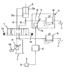
- FIG. 1 is a circuit diagram showing a circuit pressure control apparatus according to a first embodiment of the present invention.
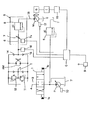
- FIG. 2 is a circuit diagram showing a hydraulic control circuit of the construction equipment in the second embodiment.
- the first embodiment shown in FIG. 1 is a hydraulic circuit in which a variable displacement hydraulic pump P and a tank T are connected to a cylinder 2 as an actuator via an operation valve 1.
- the operation valve 1 when the operation valve 1 is held at the neutral position, the communication between the hydraulic pump P and the tank T and the cylinder 2 is blocked.
- the hydraulic pump P When the operation valve 1 is switched from the neutral position to either the left or right switching position, the hydraulic pump P is communicated with either the piston side chamber 2a or the rod side chamber 2b of the cylinder 2 via the connection passage 3 or 4. At the same time, the tank T communicates with either the rod side chamber 2b or the piston side chamber 2a of the cylinder 2 via the connection passage 4 or 3. Thereby, the cylinder 2 expands or contracts.
- a main relief valve 5 is provided in a branch passage branched from a hydraulic passage connecting the hydraulic pump P and the operation valve 1. The pressure supplied to the entire circuit from the hydraulic pump P is controlled by opening and closing the main relief valve 5.
- a branch passage 6 connected to the tank T is connected to the connection passage 3 that connects the operation valve 1 and the piston side chamber 2a of the cylinder 2.
- the branch passage 6 is provided with a variable throttle valve 7 and a relief valve 8 in order from the upstream side.
- variable throttle valve 7 and the relief valve 8 constitute the circuit pressure control device S of the present invention.
- the variable throttle valve 7 includes an electromagnetic mechanism 7a.
- the electromagnetic mechanism 7 a operates in accordance with an electrical signal from the controller C, and the opening degree of the variable throttle valve 7 is adjusted.
- the variable throttle valve 7 is controlled by the controller C.
- a joystick 9 is connected to the controller C. When the operator operates the joystick 9, a predetermined operation signal is input to the controller C every time the joystick 9 is operated.
- the controller C controls the opening degree of the variable throttle valve 7 by operating the electromagnetic mechanism 7a according to the operation signal.
- the opening degree of the variable throttle valve 7 changes according to the control signal for controlling the electromagnetic mechanism 7a from the controller C.
- the joystick 9 operates the pilot pressure led to the pilot chambers 1a and 1b of the operation valve 1, and the control signal input to the electromagnetic mechanism 7a of the variable throttle valve 7 is proportional to the switching amount of the operation valve 1. become.
- the relief valve 8 includes a spring.
- the upper limit value of the upstream pressure is set by the spring force of the spring.
- the set pressure of the relief valve 8 is set to be lower than the set pressure of the main relief valve 5.
- a plurality of actuators are connected to the hydraulic pump P of the first embodiment.
- the plurality of actuators are connected to each other via a hydraulic circuit (not shown).
- the hydraulic pump P is provided with a regulator 10 that controls the discharge amount of the hydraulic pump P, and the tilt angle of the hydraulic pump P is controlled by the regulator 10.
- the controller C When the operation lever of the joystick 9 is operated, the controller C outputs a control signal proportional to the operation amount of the operation lever.
- the pilot pressure corresponding to the control signal is introduced to the pilot chamber 1a of the operation valve 1, the operation valve 1 is switched from the neutral position to the left side position in the drawing according to the control signal from the controller C.
- the operator operates the controller C and changes the set pressure of the hydraulic circuit by the circuit pressure control device S.
- the circuit pressure control device S changes the pressure in the connection passage 3 and the branch passage 6 to increase or decrease the pressure supplied to the cylinder 2 by the operation of the operator.
- a control signal for maximizing the opening degree of the variable throttle valve 7 is output from the controller C. If the opening degree of the variable throttle valve 7 is maximized, the set pressure of the hydraulic circuit including the cylinder 2 by the circuit pressure control device S becomes the set pressure of the relief valve 8 that is relatively low.
- the set pressure of the hydraulic circuit by the circuit pressure control device S can be kept higher as the opening of the variable throttle valve 7 is reduced.
- the load pressure of the cylinder 2 acts on the relief valve 8 via the variable throttle valve 7. That is, the higher the load pressure of the cylinder 2, the higher the pressure on the upstream side of the relief valve 8.
- the relief valve 8 is opened if the load pressure of the cylinder 2 reaches the set pressure of the relief valve 8.
- the set pressure of the hydraulic circuit upstream of the circuit pressure control device S is the highest set pressure (upper limit value) determined according to the opening of the variable throttle valve 7 from the lowest set pressure (lower limit value) of the relief valve 8. ) Can be controlled linearly.
- the set pressure of the hydraulic circuit communicating with the cylinder 2 can be controlled linearly in this way, for example, when the load on the cylinder 2 is small, the set pressure can be kept low to reduce the load on the hydraulic pump P. As a matter of course, it is possible to cope with a case where the load on the cylinder 2 is large.
- the set pressure can be variably controlled linearly by the variable throttle valve and the relief valve. It can be controlled in detail.
- FIG. 2 showing the second embodiment is a circuit diagram focusing on the turning motor RM in the control circuit of the construction machine. Therefore, in 2nd Embodiment, illustration of the other actuator used for a construction machine is abbreviate
- the turning motor RM is connected to the operation valve 1 for turning motor control via the connection passages 3 and 4.
- Brake valves 11 and 12 are connected to the connection passages 3 and 4, respectively.
- connection passage 3 When the operation valve 1 is switched from the neutral position to the left side in the drawing from the above state, for example, one connection passage 3 is connected to the hydraulic pump P, and the other connection passage 4 communicates with the tank T. Accordingly, pressure oil is supplied from the connection passage 3 to rotate the turning motor RM, and return oil from the turning motor RM is returned to the tank via the other connection passage 4.
- connection passage 4 When the operation valve 1 is switched in the opposite direction, the discharge oil from the hydraulic pump P is supplied to the connection passage 4, the connection passage 3 communicates with the tank T, and the swing motor RM rotates in the reverse direction. become.
- the brake valve 11 or 12 When the swing motor RM is driven as described above, the brake valve 11 or 12 exhibits the function of a relief valve, and when the connection passages 3 and 4 become the set pressure or higher, the brake valves 11 and 12 are opened. Thus, the pressure in the high-pressure side passage is controlled within the set pressure.
- the swing motor RM performs pumping action. To do.
- the connection passages 3 and 4, the swing motor RM, and the brake valve 11 or 12 form a closed circuit, and the brake valve 11 or 12 converts the inertia energy of the swing motor RM into heat energy. .
- connection passages 3 and 4 merge with each other via check valves 13 and 14, respectively.
- the supply passage 15 is connected to the junction.
- the check valves 13 and 14 allow only the flow from the connection passages 3 and 4 to the supply passage 15 respectively.
- a variable displacement hydraulic motor M is connected to the most downstream side of the supply passage 15 as described above, and a generator G is linked to the hydraulic motor M.
- the generator G is connected to the battery 16 via the inverter I. Connected to.
- the battery 16 is connected to the controller C via a signal line for detecting the state of the battery 16. For this reason, the controller C can grasp the charging state of the battery 16.
- the hydraulic motor M is provided with an inclination controller 17 that electrically controls the inclination angle of the hydraulic motor M, and the inclination controller 17 is connected to the controller C via a signal line.
- a circuit pressure control device S is provided in the supply passage 15 as described above.
- the circuit pressure control device S includes a variable throttle valve 7 having an electromagnetic mechanism 7 a and a relief valve 8 provided on the downstream side of the variable throttle valve 7. These variable throttle valve 7 and relief valve 8 are the same as in the first embodiment.
- the set pressure when the variable throttle valve 7 is slightly open is set to be lower than the set pressure of the brake valves 11 and 12.
- a pressure sensor 18 for detecting the pressure at the time of turning of the turning motor RM or the pressure at the time of braking is provided, and the pressure signal of this pressure sensor 18 is input to the controller C. .
- the hydraulic pump P is provided with the same regulator 10 as in the first embodiment.
- the turning motor RM rotates within the set pressure range of the brake valves 11 and 12 as described above.
- the load pressure of the turning motor RM is detected by the pressure sensor 18 and input to the controller C, and the switching amount of the operation valve 1 is input to the controller C as the operation amount of the joystick 9.
- the controller C compares the difference between the set pressure of the brake valves 11 and 12 and the load pressure of the swing motor RM, and determines whether or not the load pressure exceeds a threshold value set in advance in the controller C. To do.
- the controller C controls the opening and closing of the variable throttle valve 7 from the load pressure of the swing motor RM and the threshold value. That is, when the load pressure of the swing motor RM exceeds the threshold value, the controller C operates the electromagnetic mechanism 7a to reduce the opening of the variable throttle valve 7, or closes the variable throttle valve 7. .
- the opening of the variable throttle valve 7 is reduced to increase the set pressure of the hydraulic circuit by the circuit pressure control device S, and the set pressure of the circuit is maximized by completely closing the variable throttle valve 7. it can.
- the turning motor RM can be driven within the set pressure range of the brake valves 11 and 12.
- the controller C determines that the load pressure of the turning motor RM is equal to or lower than the threshold value
- the controller C drives the electromagnetic mechanism 7a to open the variable throttle valve 7.
- the variable throttle valve 7 is opened
- the relief valve 8 is opened with the pressure at that time, so that the surplus flow rate with respect to the swing motor RM is supplied to the hydraulic motor M via the supply passage 15 to rotate the hydraulic motor M.
- the generator G rotates to generate power, and the generated power is charged to the battery 16 via the inverter I.
- the controller C controls the opening degree of the variable throttle valve 7 based on the difference between the required flow rate and the threshold value.
- the set pressure of the circuit pressure control device S composed of the variable throttle valve 7 and the relief valve 8 is the lowest, and when the variable throttle valve 7 is fully closed, The set pressure of the hydraulic circuit by the pressure control device S is the highest.
- variable throttle valve 7 may be controlled directly by the operator or automatically by the controller C.
- the set pressure of the circuit can be variably controlled linearly. Since linear control can be performed in this way, surplus oil that changes in accordance with the operating state of the turning motor RM can be appropriately supplied to the hydraulic motor M, and energy efficiency can be increased by that amount and energy saving can be achieved.
- the controller C can control the opening degree of the variable throttle valve 7. For example, when the controller C determines that the battery 16 is sufficiently charged from a signal related to the charge amount input from the battery 16 to the controller C, the tilt angle controller 17 is operated to tilt the hydraulic motor M. Is almost zero. In such a state, the controller C can prioritize the drive of the turning motor RM by fully closing the variable throttle valve 7.
- the controller C linearly sets the set pressure of the circuit by the circuit pressure control device S while combining the pressure signal from the pressure sensor 18 and the tilt signal from the tilt controller 17 of the hydraulic motor M. Variable control is possible.
- the second embodiment can be used not only to supply surplus oil to the hydraulic motor M for power generation but also to supply surplus oil to other devices.
- the actuator to be controlled can be applied not only to the turning motor RM but also to general equipment.
- the second embodiment of the present invention it is possible to increase energy efficiency by appropriately supplying surplus energy that changes in accordance with the operating state of the actuator that is a control target to other actuators, thereby saving energy accordingly. Can be achieved.
- surplus energy that changes in accordance with the change in the driving pressure of the turning motor can be supplied to the hydraulic motor that rotates the generator. Since the turning pressure may be low, at this time, the degree of opening of the variable throttle valve can be made relatively large so that a large amount of excess oil can be guided to the hydraulic motor.
- the power generation efficiency can be increased by effectively turning the hydraulic motor without hindering the drive efficiency of the swing motor. be able to.
- the circuit pressure control device can be used for a construction machine having a power generation function.
Priority Applications (5)
| Application Number | Priority Date | Filing Date | Title |
|---|---|---|---|
| US14/373,374 US9080582B2 (en) | 2012-01-25 | 2013-01-21 | Circuit pressure control device, hydraulic control circuit using circuit pressure control unit, and hydraulic control circuit of construction machine |
| KR1020147016623A KR20140087057A (ko) | 2012-01-25 | 2013-01-21 | 회로압 제어 장치, 이 회로압 제어 장치를 사용한 유압 제어 회로 및 건설 기계의 유압 제어 회로 |
| EP13740680.7A EP2806171B1 (de) | 2012-01-25 | 2013-01-21 | Hydraulische schaltung mit systemdrucksteuerungsvorrichtung |
| KR1020157016761A KR101953430B1 (ko) | 2012-01-25 | 2013-01-21 | 회로압 제어 장치, 이 회로압 제어 장치를 사용한 유압 제어 회로 및 건설 기계의 유압 제어 회로 |
| CN201380004414.5A CN104011399B (zh) | 2012-01-25 | 2013-01-21 | 油压控制回路以及建筑机械的油压控制回路 |
Applications Claiming Priority (2)
| Application Number | Priority Date | Filing Date | Title |
|---|---|---|---|
| JP2012013186A JP5513535B2 (ja) | 2012-01-25 | 2012-01-25 | 回路圧制御装置、この回路圧制御装置を用いた油圧制御回路及び建設機械の油圧制御回路 |
| JP2012-013186 | 2012-01-25 |
Publications (1)
| Publication Number | Publication Date |
|---|---|
| WO2013111705A1 true WO2013111705A1 (ja) | 2013-08-01 |
Family
ID=48873425
Family Applications (1)
| Application Number | Title | Priority Date | Filing Date |
|---|---|---|---|
| PCT/JP2013/051091 WO2013111705A1 (ja) | 2012-01-25 | 2013-01-21 | 回路圧制御装置、この回路圧制御装置を用いた油圧制御回路、及び建設機械の油圧制御回路 |
Country Status (6)
| Country | Link |
|---|---|
| US (1) | US9080582B2 (de) |
| EP (1) | EP2806171B1 (de) |
| JP (1) | JP5513535B2 (de) |
| KR (2) | KR101953430B1 (de) |
| CN (1) | CN104011399B (de) |
| WO (1) | WO2013111705A1 (de) |
Cited By (2)
| Publication number | Priority date | Publication date | Assignee | Title |
|---|---|---|---|---|
| JP2015067993A (ja) * | 2013-09-27 | 2015-04-13 | ダイキン工業株式会社 | 建設機械 |
| CN112173085A (zh) * | 2020-09-25 | 2021-01-05 | 中国直升机设计研究所 | 一种直升机起落架收放液压控制系统及方法 |
Families Citing this family (7)
| Publication number | Priority date | Publication date | Assignee | Title |
|---|---|---|---|---|
| JP6155159B2 (ja) * | 2013-10-11 | 2017-06-28 | Kyb株式会社 | ハイブリッド建設機械の制御システム |
| CN104196780A (zh) * | 2014-09-18 | 2014-12-10 | 芜湖高昌液压机电技术有限公司 | 举升机出口溢流节流阀调速回路 |
| JP6740132B2 (ja) | 2014-10-06 | 2020-08-12 | 住友重機械工業株式会社 | ショベル |
| WO2016158708A1 (ja) * | 2015-03-27 | 2016-10-06 | 住友重機械工業株式会社 | ショベルおよびショベルの駆動方法 |
| US10648254B2 (en) * | 2018-04-13 | 2020-05-12 | Forum Us, Inc. | Wrench assembly with proportional grip circuit |
| CN109914515B (zh) * | 2019-03-29 | 2021-04-09 | 三一重机有限公司 | 回转操作控制系统及方法 |
| DE102020213039A1 (de) * | 2020-10-15 | 2022-04-21 | Robert Bosch Gesellschaft mit beschränkter Haftung | Anordnung und Verfahren zur Ansteuerung eines Hubwerkes |
Citations (4)
| Publication number | Priority date | Publication date | Assignee | Title |
|---|---|---|---|---|
| JPS63214505A (ja) * | 1987-03-02 | 1988-09-07 | Daikin Ind Ltd | サ−ジ圧吸収回路 |
| JPH0473410A (ja) * | 1990-07-13 | 1992-03-09 | Kosumetsuku:Kk | 残圧保持機能付き圧油給排回路及びその圧油給排回路に用いる残圧保持用弁装置 |
| JPH06174122A (ja) | 1992-11-30 | 1994-06-24 | Kayaba Ind Co Ltd | リリーフ弁 |
| JP2011017427A (ja) | 2009-07-10 | 2011-01-27 | Kyb Co Ltd | ハイブリッド建設機械の制御装置 |
Family Cites Families (17)
| Publication number | Priority date | Publication date | Assignee | Title |
|---|---|---|---|---|
| DE1482814A1 (de) | 1961-01-25 | 1969-08-14 | Lely Nv C Van Der | Heuwender |
| DE2037626A1 (de) * | 1970-07-29 | 1972-02-03 | Demag Kampnagel Gmbh | Vorrichtung zum Betätigen und Lüften einer Bremse, insbesondere einer Kettennußbremse einer Ankerwinde |
| FR2186610B1 (de) * | 1972-05-23 | 1975-08-29 | Verlinde Sa | |
| DE2357283A1 (de) * | 1973-11-16 | 1975-05-28 | Kloeckner Humboldt Deutz Ag | Steuereinrichtung fuer ein aus einer brennkraftmaschine und einem hydrostatischen getriebe gebildetes antriebsaggregat |
| JPS6132850Y2 (de) * | 1978-12-05 | 1986-09-25 | ||
| ES509159A0 (es) * | 1982-01-14 | 1983-02-01 | Bendiberica Sa | Perfeccionamientos en distribuidores hidraulicos para servomecanismos. |
| ES518114A0 (es) * | 1982-12-11 | 1983-11-16 | Bendiberica Sa | Perfeccionamientos en sistemas de mando hidraulico para servomecanismos. |
| ES527578A0 (es) * | 1983-11-18 | 1984-11-01 | Bendiberica Sa | Perfeccionamientos en distribuidores hidraulicos para servomecanismos |
| CN1011675B (zh) * | 1987-05-23 | 1991-02-20 | 青岛家具研究所 | 刨花模压一次加工制品及其制造方法和专用设备 |
| US5038878A (en) * | 1988-10-28 | 1991-08-13 | Nissan Motor Co., Ltd. | Variable assist power steering apparatus |
| CN1071854C (zh) * | 1995-07-10 | 2001-09-26 | 日立建机株式会社 | 液压驱动系统 |
| CN2936702Y (zh) * | 2006-08-16 | 2007-08-22 | 天津市天锻压力机有限公司 | 液压机缓冲器的液压控制系统 |
| JP5078692B2 (ja) * | 2008-03-26 | 2012-11-21 | カヤバ工業株式会社 | ハイブリッド建設機械の制御装置 |
| CN201246357Y (zh) * | 2008-05-15 | 2009-05-27 | 上海新力机器厂 | 折弯机液压控制系统 |
| KR20080001986U (ko) * | 2008-05-31 | 2008-06-19 | 임창후 | 굴삭기의 연료 절약장치 |
| CN101940092B (zh) * | 2010-07-18 | 2012-09-12 | 吉林大学 | 双自由度单铰接仿形机构 |
| CN102320228B (zh) * | 2011-08-23 | 2013-05-08 | 中国北方车辆研究所 | 一种利用下降过程进行车姿调节的方法 |
-
2012
- 2012-01-25 JP JP2012013186A patent/JP5513535B2/ja active Active
-
2013
- 2013-01-21 KR KR1020157016761A patent/KR101953430B1/ko active IP Right Grant
- 2013-01-21 US US14/373,374 patent/US9080582B2/en active Active
- 2013-01-21 CN CN201380004414.5A patent/CN104011399B/zh active Active
- 2013-01-21 WO PCT/JP2013/051091 patent/WO2013111705A1/ja active Application Filing
- 2013-01-21 EP EP13740680.7A patent/EP2806171B1/de active Active
- 2013-01-21 KR KR1020147016623A patent/KR20140087057A/ko active Application Filing
Patent Citations (4)
| Publication number | Priority date | Publication date | Assignee | Title |
|---|---|---|---|---|
| JPS63214505A (ja) * | 1987-03-02 | 1988-09-07 | Daikin Ind Ltd | サ−ジ圧吸収回路 |
| JPH0473410A (ja) * | 1990-07-13 | 1992-03-09 | Kosumetsuku:Kk | 残圧保持機能付き圧油給排回路及びその圧油給排回路に用いる残圧保持用弁装置 |
| JPH06174122A (ja) | 1992-11-30 | 1994-06-24 | Kayaba Ind Co Ltd | リリーフ弁 |
| JP2011017427A (ja) | 2009-07-10 | 2011-01-27 | Kyb Co Ltd | ハイブリッド建設機械の制御装置 |
Non-Patent Citations (1)
| Title |
|---|
| See also references of EP2806171A4 |
Cited By (3)
| Publication number | Priority date | Publication date | Assignee | Title |
|---|---|---|---|---|
| JP2015067993A (ja) * | 2013-09-27 | 2015-04-13 | ダイキン工業株式会社 | 建設機械 |
| CN112173085A (zh) * | 2020-09-25 | 2021-01-05 | 中国直升机设计研究所 | 一种直升机起落架收放液压控制系统及方法 |
| CN112173085B (zh) * | 2020-09-25 | 2023-03-28 | 中国直升机设计研究所 | 一种直升机起落架收放液压控制系统及方法 |
Also Published As
| Publication number | Publication date |
|---|---|
| CN104011399A (zh) | 2014-08-27 |
| CN104011399B (zh) | 2016-10-12 |
| KR101953430B1 (ko) | 2019-02-28 |
| EP2806171A4 (de) | 2015-03-25 |
| JP2013151986A (ja) | 2013-08-08 |
| KR20140087057A (ko) | 2014-07-08 |
| JP5513535B2 (ja) | 2014-06-04 |
| US9080582B2 (en) | 2015-07-14 |
| US20150013323A1 (en) | 2015-01-15 |
| KR20150080022A (ko) | 2015-07-08 |
| EP2806171B1 (de) | 2017-03-29 |
| EP2806171A1 (de) | 2014-11-26 |
Similar Documents
| Publication | Publication Date | Title |
|---|---|---|
| WO2013111705A1 (ja) | 回路圧制御装置、この回路圧制御装置を用いた油圧制御回路、及び建設機械の油圧制御回路 | |
| KR101507646B1 (ko) | 하이브리드 건설 기계의 제어 시스템 | |
| JP5172477B2 (ja) | ハイブリッド建設機械の制御装置 | |
| US9476437B2 (en) | Boom driving device | |
| KR101421362B1 (ko) | 하이브리드 건설 기계의 제어 시스템 | |
| US8467934B2 (en) | Controller of hybrid construction machine | |
| KR101218018B1 (ko) | 하이브리드 건설 기계의 제어 장치 | |
| US9920502B2 (en) | Control system for hybrid construction machine | |
| KR101595584B1 (ko) | 하이브리드 건설기계의 제어장치 | |
| US9664209B2 (en) | Control system for hybrid construction machine | |
| WO2014017492A1 (ja) | 建設機械の制御システム | |
| JP2007263160A (ja) | エネルギー変換装置 | |
| WO2009131085A1 (ja) | ハイブリッド建設機械の制御装置 | |
| WO2016084421A1 (ja) | ハイブリッド建設機械の制御システム | |
| JP5197479B2 (ja) | ハイブリッド建設機械 | |
| US9359743B2 (en) | Control system for hybrid construction machine | |
| US9124133B2 (en) | Charging apparatus for construction machine | |
| JP2009235718A (ja) | ハイブリッド建設機械の制御装置 | |
| JP2014228101A (ja) | 作業機械の油圧駆動装置 |
Legal Events
| Date | Code | Title | Description |
|---|---|---|---|
| 121 | Ep: the epo has been informed by wipo that ep was designated in this application |
Ref document number: 13740680 Country of ref document: EP Kind code of ref document: A1 |
|
| ENP | Entry into the national phase |
Ref document number: 20147016623 Country of ref document: KR Kind code of ref document: A |
|
| WWE | Wipo information: entry into national phase |
Ref document number: 14373374 Country of ref document: US |
|
| NENP | Non-entry into the national phase |
Ref country code: DE |
|
| REEP | Request for entry into the european phase |
Ref document number: 2013740680 Country of ref document: EP |
|
| WWE | Wipo information: entry into national phase |
Ref document number: 2013740680 Country of ref document: EP |