EP2806171B1 - Hydraulische schaltung mit systemdrucksteuerungsvorrichtung - Google Patents
Hydraulische schaltung mit systemdrucksteuerungsvorrichtung Download PDFInfo
- Publication number
- EP2806171B1 EP2806171B1 EP13740680.7A EP13740680A EP2806171B1 EP 2806171 B1 EP2806171 B1 EP 2806171B1 EP 13740680 A EP13740680 A EP 13740680A EP 2806171 B1 EP2806171 B1 EP 2806171B1
- Authority
- EP
- European Patent Office
- Prior art keywords
- pressure
- valve
- actuator
- variable throttle
- throttle valve
- Prior art date
- Legal status (The legal status is an assumption and is not a legal conclusion. Google has not performed a legal analysis and makes no representation as to the accuracy of the status listed.)
- Active
Links
Images
Classifications
-
- F—MECHANICAL ENGINEERING; LIGHTING; HEATING; WEAPONS; BLASTING
- F15—FLUID-PRESSURE ACTUATORS; HYDRAULICS OR PNEUMATICS IN GENERAL
- F15B—SYSTEMS ACTING BY MEANS OF FLUIDS IN GENERAL; FLUID-PRESSURE ACTUATORS, e.g. SERVOMOTORS; DETAILS OF FLUID-PRESSURE SYSTEMS, NOT OTHERWISE PROVIDED FOR
- F15B13/00—Details of servomotor systems ; Valves for servomotor systems
- F15B13/10—Special arrangements for operating the actuated device with or without using fluid pressure, e.g. for emergency use
-
- E—FIXED CONSTRUCTIONS
- E02—HYDRAULIC ENGINEERING; FOUNDATIONS; SOIL SHIFTING
- E02F—DREDGING; SOIL-SHIFTING
- E02F9/00—Component parts of dredgers or soil-shifting machines, not restricted to one of the kinds covered by groups E02F3/00 - E02F7/00
- E02F9/08—Superstructures; Supports for superstructures
- E02F9/10—Supports for movable superstructures mounted on travelling or walking gears or on other superstructures
- E02F9/12—Slewing or traversing gears
- E02F9/121—Turntables, i.e. structure rotatable about 360°
- E02F9/123—Drives or control devices specially adapted therefor
-
- E—FIXED CONSTRUCTIONS
- E02—HYDRAULIC ENGINEERING; FOUNDATIONS; SOIL SHIFTING
- E02F—DREDGING; SOIL-SHIFTING
- E02F9/00—Component parts of dredgers or soil-shifting machines, not restricted to one of the kinds covered by groups E02F3/00 - E02F7/00
- E02F9/20—Drives; Control devices
- E02F9/22—Hydraulic or pneumatic drives
- E02F9/2221—Control of flow rate; Load sensing arrangements
- E02F9/2225—Control of flow rate; Load sensing arrangements using pressure-compensating valves
-
- E—FIXED CONSTRUCTIONS
- E02—HYDRAULIC ENGINEERING; FOUNDATIONS; SOIL SHIFTING
- E02F—DREDGING; SOIL-SHIFTING
- E02F9/00—Component parts of dredgers or soil-shifting machines, not restricted to one of the kinds covered by groups E02F3/00 - E02F7/00
- E02F9/20—Drives; Control devices
- E02F9/22—Hydraulic or pneumatic drives
- E02F9/225—Control of steering, e.g. for hydraulic motors driving the vehicle tracks
-
- E—FIXED CONSTRUCTIONS
- E02—HYDRAULIC ENGINEERING; FOUNDATIONS; SOIL SHIFTING
- E02F—DREDGING; SOIL-SHIFTING
- E02F9/00—Component parts of dredgers or soil-shifting machines, not restricted to one of the kinds covered by groups E02F3/00 - E02F7/00
- E02F9/20—Drives; Control devices
- E02F9/22—Hydraulic or pneumatic drives
- E02F9/2278—Hydraulic circuits
- E02F9/2296—Systems with a variable displacement pump
-
- F—MECHANICAL ENGINEERING; LIGHTING; HEATING; WEAPONS; BLASTING
- F15—FLUID-PRESSURE ACTUATORS; HYDRAULICS OR PNEUMATICS IN GENERAL
- F15B—SYSTEMS ACTING BY MEANS OF FLUIDS IN GENERAL; FLUID-PRESSURE ACTUATORS, e.g. SERVOMOTORS; DETAILS OF FLUID-PRESSURE SYSTEMS, NOT OTHERWISE PROVIDED FOR
- F15B11/00—Servomotor systems without provision for follow-up action; Circuits therefor
- F15B11/02—Systems essentially incorporating special features for controlling the speed or actuating force of an output member
- F15B11/028—Systems essentially incorporating special features for controlling the speed or actuating force of an output member for controlling the actuating force
-
- F—MECHANICAL ENGINEERING; LIGHTING; HEATING; WEAPONS; BLASTING
- F15—FLUID-PRESSURE ACTUATORS; HYDRAULICS OR PNEUMATICS IN GENERAL
- F15B—SYSTEMS ACTING BY MEANS OF FLUIDS IN GENERAL; FLUID-PRESSURE ACTUATORS, e.g. SERVOMOTORS; DETAILS OF FLUID-PRESSURE SYSTEMS, NOT OTHERWISE PROVIDED FOR
- F15B21/00—Common features of fluid actuator systems; Fluid-pressure actuator systems or details thereof, not covered by any other group of this subclass
- F15B21/14—Energy-recuperation means
-
- F—MECHANICAL ENGINEERING; LIGHTING; HEATING; WEAPONS; BLASTING
- F15—FLUID-PRESSURE ACTUATORS; HYDRAULICS OR PNEUMATICS IN GENERAL
- F15B—SYSTEMS ACTING BY MEANS OF FLUIDS IN GENERAL; FLUID-PRESSURE ACTUATORS, e.g. SERVOMOTORS; DETAILS OF FLUID-PRESSURE SYSTEMS, NOT OTHERWISE PROVIDED FOR
- F15B2211/00—Circuits for servomotor systems
- F15B2211/20—Fluid pressure source, e.g. accumulator or variable axial piston pump
- F15B2211/205—Systems with pumps
- F15B2211/2053—Type of pump
- F15B2211/20546—Type of pump variable capacity
-
- F—MECHANICAL ENGINEERING; LIGHTING; HEATING; WEAPONS; BLASTING
- F15—FLUID-PRESSURE ACTUATORS; HYDRAULICS OR PNEUMATICS IN GENERAL
- F15B—SYSTEMS ACTING BY MEANS OF FLUIDS IN GENERAL; FLUID-PRESSURE ACTUATORS, e.g. SERVOMOTORS; DETAILS OF FLUID-PRESSURE SYSTEMS, NOT OTHERWISE PROVIDED FOR
- F15B2211/00—Circuits for servomotor systems
- F15B2211/40—Flow control
- F15B2211/405—Flow control characterised by the type of flow control means or valve
- F15B2211/40515—Flow control characterised by the type of flow control means or valve with variable throttles or orifices
-
- F—MECHANICAL ENGINEERING; LIGHTING; HEATING; WEAPONS; BLASTING
- F15—FLUID-PRESSURE ACTUATORS; HYDRAULICS OR PNEUMATICS IN GENERAL
- F15B—SYSTEMS ACTING BY MEANS OF FLUIDS IN GENERAL; FLUID-PRESSURE ACTUATORS, e.g. SERVOMOTORS; DETAILS OF FLUID-PRESSURE SYSTEMS, NOT OTHERWISE PROVIDED FOR
- F15B2211/00—Circuits for servomotor systems
- F15B2211/40—Flow control
- F15B2211/41—Flow control characterised by the positions of the valve element
- F15B2211/413—Flow control characterised by the positions of the valve element the positions being continuously variable, e.g. as realised by proportional valves
-
- F—MECHANICAL ENGINEERING; LIGHTING; HEATING; WEAPONS; BLASTING
- F15—FLUID-PRESSURE ACTUATORS; HYDRAULICS OR PNEUMATICS IN GENERAL
- F15B—SYSTEMS ACTING BY MEANS OF FLUIDS IN GENERAL; FLUID-PRESSURE ACTUATORS, e.g. SERVOMOTORS; DETAILS OF FLUID-PRESSURE SYSTEMS, NOT OTHERWISE PROVIDED FOR
- F15B2211/00—Circuits for servomotor systems
- F15B2211/40—Flow control
- F15B2211/415—Flow control characterised by the connections of the flow control means in the circuit
- F15B2211/41581—Flow control characterised by the connections of the flow control means in the circuit being connected to an output member and a return line
-
- F—MECHANICAL ENGINEERING; LIGHTING; HEATING; WEAPONS; BLASTING
- F15—FLUID-PRESSURE ACTUATORS; HYDRAULICS OR PNEUMATICS IN GENERAL
- F15B—SYSTEMS ACTING BY MEANS OF FLUIDS IN GENERAL; FLUID-PRESSURE ACTUATORS, e.g. SERVOMOTORS; DETAILS OF FLUID-PRESSURE SYSTEMS, NOT OTHERWISE PROVIDED FOR
- F15B2211/00—Circuits for servomotor systems
- F15B2211/40—Flow control
- F15B2211/42—Flow control characterised by the type of actuation
- F15B2211/426—Flow control characterised by the type of actuation electrically or electronically
-
- F—MECHANICAL ENGINEERING; LIGHTING; HEATING; WEAPONS; BLASTING
- F15—FLUID-PRESSURE ACTUATORS; HYDRAULICS OR PNEUMATICS IN GENERAL
- F15B—SYSTEMS ACTING BY MEANS OF FLUIDS IN GENERAL; FLUID-PRESSURE ACTUATORS, e.g. SERVOMOTORS; DETAILS OF FLUID-PRESSURE SYSTEMS, NOT OTHERWISE PROVIDED FOR
- F15B2211/00—Circuits for servomotor systems
- F15B2211/50—Pressure control
- F15B2211/505—Pressure control characterised by the type of pressure control means
- F15B2211/50509—Pressure control characterised by the type of pressure control means the pressure control means controlling a pressure upstream of the pressure control means
- F15B2211/50518—Pressure control characterised by the type of pressure control means the pressure control means controlling a pressure upstream of the pressure control means using pressure relief valves
-
- F—MECHANICAL ENGINEERING; LIGHTING; HEATING; WEAPONS; BLASTING
- F15—FLUID-PRESSURE ACTUATORS; HYDRAULICS OR PNEUMATICS IN GENERAL
- F15B—SYSTEMS ACTING BY MEANS OF FLUIDS IN GENERAL; FLUID-PRESSURE ACTUATORS, e.g. SERVOMOTORS; DETAILS OF FLUID-PRESSURE SYSTEMS, NOT OTHERWISE PROVIDED FOR
- F15B2211/00—Circuits for servomotor systems
- F15B2211/50—Pressure control
- F15B2211/515—Pressure control characterised by the connections of the pressure control means in the circuit
- F15B2211/5159—Pressure control characterised by the connections of the pressure control means in the circuit being connected to an output member and a return line
-
- F—MECHANICAL ENGINEERING; LIGHTING; HEATING; WEAPONS; BLASTING
- F15—FLUID-PRESSURE ACTUATORS; HYDRAULICS OR PNEUMATICS IN GENERAL
- F15B—SYSTEMS ACTING BY MEANS OF FLUIDS IN GENERAL; FLUID-PRESSURE ACTUATORS, e.g. SERVOMOTORS; DETAILS OF FLUID-PRESSURE SYSTEMS, NOT OTHERWISE PROVIDED FOR
- F15B2211/00—Circuits for servomotor systems
- F15B2211/50—Pressure control
- F15B2211/55—Pressure control for limiting a pressure up to a maximum pressure, e.g. by using a pressure relief valve
-
- F—MECHANICAL ENGINEERING; LIGHTING; HEATING; WEAPONS; BLASTING
- F15—FLUID-PRESSURE ACTUATORS; HYDRAULICS OR PNEUMATICS IN GENERAL
- F15B—SYSTEMS ACTING BY MEANS OF FLUIDS IN GENERAL; FLUID-PRESSURE ACTUATORS, e.g. SERVOMOTORS; DETAILS OF FLUID-PRESSURE SYSTEMS, NOT OTHERWISE PROVIDED FOR
- F15B2211/00—Circuits for servomotor systems
- F15B2211/60—Circuit components or control therefor
- F15B2211/61—Secondary circuits
- F15B2211/611—Diverting circuits, e.g. for cooling or filtering
-
- F—MECHANICAL ENGINEERING; LIGHTING; HEATING; WEAPONS; BLASTING
- F15—FLUID-PRESSURE ACTUATORS; HYDRAULICS OR PNEUMATICS IN GENERAL
- F15B—SYSTEMS ACTING BY MEANS OF FLUIDS IN GENERAL; FLUID-PRESSURE ACTUATORS, e.g. SERVOMOTORS; DETAILS OF FLUID-PRESSURE SYSTEMS, NOT OTHERWISE PROVIDED FOR
- F15B2211/00—Circuits for servomotor systems
- F15B2211/60—Circuit components or control therefor
- F15B2211/63—Electronic controllers
- F15B2211/6303—Electronic controllers using input signals
- F15B2211/6306—Electronic controllers using input signals representing a pressure
- F15B2211/6313—Electronic controllers using input signals representing a pressure the pressure being a load pressure
-
- F—MECHANICAL ENGINEERING; LIGHTING; HEATING; WEAPONS; BLASTING
- F15—FLUID-PRESSURE ACTUATORS; HYDRAULICS OR PNEUMATICS IN GENERAL
- F15B—SYSTEMS ACTING BY MEANS OF FLUIDS IN GENERAL; FLUID-PRESSURE ACTUATORS, e.g. SERVOMOTORS; DETAILS OF FLUID-PRESSURE SYSTEMS, NOT OTHERWISE PROVIDED FOR
- F15B2211/00—Circuits for servomotor systems
- F15B2211/60—Circuit components or control therefor
- F15B2211/63—Electronic controllers
- F15B2211/6303—Electronic controllers using input signals
- F15B2211/6346—Electronic controllers using input signals representing a state of input means, e.g. joystick position
-
- F—MECHANICAL ENGINEERING; LIGHTING; HEATING; WEAPONS; BLASTING
- F15—FLUID-PRESSURE ACTUATORS; HYDRAULICS OR PNEUMATICS IN GENERAL
- F15B—SYSTEMS ACTING BY MEANS OF FLUIDS IN GENERAL; FLUID-PRESSURE ACTUATORS, e.g. SERVOMOTORS; DETAILS OF FLUID-PRESSURE SYSTEMS, NOT OTHERWISE PROVIDED FOR
- F15B2211/00—Circuits for servomotor systems
- F15B2211/60—Circuit components or control therefor
- F15B2211/665—Methods of control using electronic components
- F15B2211/6653—Pressure control
-
- F—MECHANICAL ENGINEERING; LIGHTING; HEATING; WEAPONS; BLASTING
- F15—FLUID-PRESSURE ACTUATORS; HYDRAULICS OR PNEUMATICS IN GENERAL
- F15B—SYSTEMS ACTING BY MEANS OF FLUIDS IN GENERAL; FLUID-PRESSURE ACTUATORS, e.g. SERVOMOTORS; DETAILS OF FLUID-PRESSURE SYSTEMS, NOT OTHERWISE PROVIDED FOR
- F15B2211/00—Circuits for servomotor systems
- F15B2211/70—Output members, e.g. hydraulic motors or cylinders or control therefor
- F15B2211/705—Output members, e.g. hydraulic motors or cylinders or control therefor characterised by the type of output members or actuators
- F15B2211/7058—Rotary output members
-
- F—MECHANICAL ENGINEERING; LIGHTING; HEATING; WEAPONS; BLASTING
- F15—FLUID-PRESSURE ACTUATORS; HYDRAULICS OR PNEUMATICS IN GENERAL
- F15B—SYSTEMS ACTING BY MEANS OF FLUIDS IN GENERAL; FLUID-PRESSURE ACTUATORS, e.g. SERVOMOTORS; DETAILS OF FLUID-PRESSURE SYSTEMS, NOT OTHERWISE PROVIDED FOR
- F15B2211/00—Circuits for servomotor systems
- F15B2211/80—Other types of control related to particular problems or conditions
- F15B2211/88—Control measures for saving energy
-
- Y—GENERAL TAGGING OF NEW TECHNOLOGICAL DEVELOPMENTS; GENERAL TAGGING OF CROSS-SECTIONAL TECHNOLOGIES SPANNING OVER SEVERAL SECTIONS OF THE IPC; TECHNICAL SUBJECTS COVERED BY FORMER USPC CROSS-REFERENCE ART COLLECTIONS [XRACs] AND DIGESTS
- Y10—TECHNICAL SUBJECTS COVERED BY FORMER USPC
- Y10T—TECHNICAL SUBJECTS COVERED BY FORMER US CLASSIFICATION
- Y10T137/00—Fluid handling
- Y10T137/7722—Line condition change responsive valves
- Y10T137/7837—Direct response valves [i.e., check valve type]
Definitions
- the present invention relates to a hydraulic circuit that linearly controls a driving pressure of an actuator, a hydraulic circuit that linearly controls a driving pressure of an actuator to be controlled and can supply another actuator with residual oil of the actuator to be controlled at the same time, and a hydraulic circuit for a construction machine.
- CN 2 936 702 Y discloses a hydraulic circuit comprising a circuit pressure control unit, an actuator and an operation valve.
- the hydraulic circuit further comprises a connecting passage connecting the actuator and the operation valve, and a branch passage branched from the connecting passage.
- the circuit pressure control unit comprises a relief valve connected to the branch passage, and a variable throttle valve disposed in the branch passage upstream of the relief valve.
- a relief valve As a device that controls a driving pressure of an actuator, a relief valve is known. This relief valve sets a maximum high pressure using a spring force of a spring and controls circuit pressure by communicating the circuit with a tank when a pressure equal to or more than the maximum high pressure is applied.
- a component that changes the setting pressure for example, as disclosed in JP1994-174122A , A device with an auxiliary piston disposed at the spring where pressure is applied to the auxiliary piston, the spring is bent, and an initial setting pressure is changeable is generally known.
- JP2011-017427A As a device that controls a driving pressure of a rotating motor, a device disclosed in JP2011-017427A is known.
- This type of device includes relief valves.
- the relief valves which control driving pressure of the rotating motor, are connected in parallel with a pair of connecting passages.
- the pair of connecting passages allow the rotating motor to communicate with the hydraulic pump or the tank.
- the relief valves include an open/close valve at upstream.
- the relief valve couples a hydraulic motor for rotating an electric generator at downstream.
- the setting pressure of the relief valve is set lower than that of a main relief valve that controls the maximum high pressure of the entire circuit.
- the open/close valve is opened to guide the driving pressure of the rotating motor to the relief valve.
- the relief valve is opened with the driving pressure of the rotating motor to guide residual oil of the rotating motor to the hydraulic motor.
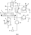
- the first embodiment illustrated in FIG. 1 is a hydraulic circuit where a variable capacity type hydraulic pump P and a tank T are connected to a cylinder 2, which is an actuator, via a directional control valve 1.
- a directional control valve 1 when the directional control valve 1 is held at a neutral position, communications between the hydraulic pump P and the tank T, and the cylinder 2 are cut off.
- the hydraulic pump P communicates with one of a piston side chamber 2a and a rod side chamber 2b of the cylinder 2 via a connecting passage 3 or 4. Accordingly, the tank T communicates with one of the rod side chamber 2b or the piston side chamber 2a of the cylinder 2 via the connecting passage 4 or 3. This extends or retracts the cylinder 2.
- the hydraulic pump P and the directional control valve 1 are connected by a hydraulic passage.
- a branch passage is branched from the hydraulic passage.
- the branch passage includes a main relief valve 5. Opening or closing the main relief valve 5 controls pressure supplied from the hydraulic pump P to the entire circuit.
- the branch passage 6 which is connected to the tank T, is connected to the connecting passage 3, which couples the directional control valve 1 and the piston side chamber 2a of the cylinder 2.
- the branch passage 6 includes a variable throttle valve 7 and a relief valve 8 in order from upstream.
- variable throttle valve 7 and the relief valve 8 constitute a circuit pressure control unit S of the present invention.
- the variable throttle valve 7 includes an electromagnetic mechanism 7a.
- the electromagnetic mechanism 7a actuates according to an electrical signal from a controller C, and an opening degree of the variable throttle valve 7 is adjusted.
- the variable throttle valve 7 is controlled by the controller C.
- a joystick 9 is connected to the controller C. When the operator operates the joystick 9, a predetermined operation signal is input to the controller C at every operation of the joystick 9.
- the controller C actuates the electromagnetic mechanism 7a according to the operation signal to control the opening degree of the variable throttle valve 7.
- the variable throttle valve 7 changes the opening degree according to the control signal, which controls the electromagnetic mechanism 7a, from the controller C.
- the joystick 9 is to operate pilot pressure guided to pilot chambers 1a and 1b of the directional control valve 1.
- the control signal input to the electromagnetic mechanism 7a of the variable throttle valve 7 is proportional to a switch amount of the directional control valve 1.
- the relief valve 8 includes a spring.
- an upper limit value of the pressure on the upstream is set by the spring force of the spring.
- the setting pressure of the relief valve 8 is set lower than the setting pressure of the main relief valve 5.
- a plurality of actuators which is not shown, is connected to the hydraulic pump P according to the first embodiment.
- the plurality of actuators are connected to one another via a hydraulic circuit, which is not shown.
- the hydraulic pump P includes a regulator 10 that controls the discharge amount of the hydraulic pump P. This regulator 10 controls the tilt angle of the hydraulic pump P.
- the operator actuates the controller C to change the setting pressure of the hydraulic circuit by the circuit pressure control unit S. That is, by operation by the operator, the circuit pressure control unit S changes the pressure of the connecting passage 3 and the branch passage 6 to increase and decrease pressure supplied to the cylinder 2.
- the control signal to set the opening degree of the variable throttle valve 7 to maximum is output from the controller C.
- the setting pressure of the hydraulic circuit including the cylinder 2 is set to the setting pressure of the relief valve 8, which is a relatively low setting pressure, by the circuit pressure control unit S.
- load pressure of the cylinder 2 is applied to the relief valve 8 via the variable throttle valve 7. That is, the higher the load pressure of the cylinder 2 becomes, the higher the pressure at the upstream of the relief valve 8 becomes.
- the relief valve 8 opens when the load pressure of the cylinder 2 reaches the setting pressure of the relief valve 8.
- the setting pressure of the hydraulic circuit upstream of the circuit pressure control unit S can be linearly controlled in a range from the lowest setting pressure of the relief valve 8 (the lower limit value) to the largest setting pressure determined according to the opening degree of the variable throttle valve 7 (the upper limit value).
- the setting pressure of the hydraulic circuit in communication with the cylinder 2 can be linearly controlled. For example, if a load of the cylinder 2 is small, the setting pressure is maintained low to reduce a load of to the hydraulic pump P. Obviously, the setting pressure can also be controlled in the case where the load of the cylinder 2 is large.
- the setting pressure can be variably-controlled linearly with the variable throttle valve and the relief valve. Accordingly, the setting pressure of the actuator to be controlled can be finely controlled according to a condition.
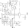
- FIG. 2 which illustrates the second embodiment, is a circuit diagram focusing on a rotating motor RM among control circuits of a construction machine. Hence, in the second embodiment, an illustration of another actuator used for the construction machine is omitted.
- the rotating motor RM is connected to the directional control valve 1 for controlling a rotating motor via the connecting passages 3 and 4.
- Brake valves 11 and 12 are connected to the respective connecting passages 3 and 4.
- one connecting passage 3 is connected to the hydraulic pump P while another connecting passage 4 communicates with the tank T. Accordingly, pressure oil is supplied from the connecting passage 3, the rotating motor RM rotates, and an return oil from the rotating motor RM is returned to the tank via the other connecting passage 4.
- the brake valve 11 or 12 serves as a relief valve.
- the connecting passages 3 and 4 are equal to or more than the setting pressure, the brake valves 11 and 12 open to control pressure of the passage at a high pressure side within the setting pressure.
- the rotating motor RM Even if the directional control valve 1 is returned to the neutral position and is closed while the rotating motor RM is rotating, the rotating motor RM continues rotating by the inertial energy and the rotating motor RM acts as a pump. At this time, the connecting passages 3 and 4, the rotating motor RM, and the brake valve 11 or 12 constitute a closed circuit. Additionally, the inertial energy of the rotating motor RM is converted into heat energy with the brake valves 11 and 12.
- the connecting passages 3 and 4 join together via respective check valves 13 and 14.
- a supply passage 15 is connected to this junction. It should be noted that the respective check valves 13 and 14 allow only a flow from the connecting passages 3 and 4 to the supply passage 15.
- a variable capacity type hydraulic motor M is connected to the most downstream of the above-described supply passage 15.
- the hydraulic motor M links an electric generator G.
- the electric generator G is connected to a battery 16 via an inverter I.
- the battery 16 is connected to the controller C via a signal line to detect a state of the battery 16. In view of this, the controller C can grasp a charge state of the battery 16.
- a tilt angle controller 17 is disposed at the hydraulic motor M.
- the tilt angle controller 17 electrically controls the tilt angle of the hydraulic motor M.
- the tilt angle controller 17 is connected to the controller C via the signal line.
- the circuit pressure control unit S is disposed at the supply passage 15 as described above.
- This circuit pressure control unit S includes the variable throttle valve 7 and the relief valve 8.
- the variable throttle valve 7 includes the electromagnetic mechanism 7a.
- the relief valve 8 is disposed downstream of the variable throttle valve 7.
- the variable throttle valve 7 and relief valve 8 are the same as those of the first embodiment.
- the setting pressure when the variable throttle valve 7 opens somewhat is set to be lower than the setting pressure of the brake valves 11 and 12.
- a pressure sensor 18 is disposed upstream of the variable throttle valve 7.
- the pressure sensor 18 detects pressure while the rotating motor RM is rotating or pressure when a brake is applied.
- the pressure signal of the pressure sensor 18 is input to the controller C.
- the regulator 10 which is the same as that of the first embodiment, is disposed at the hydraulic pump P.
- the rotating motor RM rotates in a range of the setting pressure of the brake valves 11 and 12 as described above.
- the load pressure of the rotating motor RM at this time is detected by the pressure sensor 18 and is input to the controller C.
- the switch amount of the directional control valve 1 is input to the controller C as the operation amount of the joystick 9.
- the controller C compares a difference between the setting pressure of the brake valves 11 and 12 and the load pressure of the rotating motor RM, and determines whether the load pressure exceeds a threshold value preset to the controller C or not.
- the controller C controls opening and closing of the variable throttle valve 7 according to the load pressure of the rotating motor RM and the above-described threshold value. That is, if the load pressure of the rotating motor RM exceeds the threshold value, the controller C actuates the electromagnetic mechanism 7a to decrease the opening degree of the variable throttle valve 7 or to close the variable throttle valve 7. Thus, the opening degree of the variable throttle valve 7 is decreased, the setting pressure of the hydraulic circuit is set high by the circuit pressure control unit S, and the variable throttle valve 7 is fully closed. This maximizes the setting pressure of the circuit. Accordingly, the rotating motor RM can be driven in the range of the setting pressures of the brake valves 11 and 12.
- the controller C determines that the load pressure of the rotating motor RM is equal to or less than the threshold value, the controller C drives the electromagnetic mechanism 7a to open the variable throttle valve 7. Pressure of when the variable throttle valve 7 opens also opens the relief valve 8, the extra flow rate of the rotating motor RM is supplied to the hydraulic motor M via the supply passage 15, thus making the hydraulic motor M rotate. Thus, rotation of the hydraulic motor M rotates the electric generator G, and electricity is generated. Then, the generated electric power is charged in the battery 16 via the inverter I.
- the controller C controls the opening degree of the variable throttle valve 7 based on the difference between the above-described required flow rate and the threshold value. If the variable throttle valve 7 is fully open, the setting pressure of the circuit pressure control unit S, which includes the variable throttle valve 7 and the relief valve 8, becomes the lowest. If the variable throttle valve 7 is fully closed, the highest setting pressure of the hydraulic circuit is set by the circuit pressure control unit S.
- a larger amount of flow rate can be supplied to the hydraulic motor M as the setting pressure of the circuit is lowered by the circuit pressure control unit S.
- a flow rate supplied to the hydraulic motor M is reduced by the amount of an increase in the setting pressure of the circuit by the circuit pressure control unit S.
- variable throttle valve 7 may be directly controlled by the operator or may be automatically controlled by the controller C.
- variable control can be performed linearly.
- Residual oil that changes according to the actuation condition of the rotating motor RM can be appropriately supplied to the hydraulic motor M. Energy efficiency can be increased, enabling energy saving to that extent.
- the controller C can control the opening degree of the variable throttle valve 7. For example, when the controller C determines that the battery 16 is fully charged based on a signal regarding the amount of charge input from the battery 16 to the controller C, the tilt angle controller 17 is actuated and the tilt angle of the hydraulic motor M is set to approximately zero. In this state, the controller C fully closes the variable throttle valve 7 to prioritize driving of the rotating motor RM.
- the controller C can variably-control the setting pressure of the circuit linearly by the circuit pressure control unit S in combination with a pressure signal from the pressure sensor 18, the tilt angle signal from the tilt angle controller 17 of the hydraulic motor M, or similar signal.
- the second embodiment is applicable not only to the case where residual oil is supplied to the hydraulic motor M for electric generation but is also naturally applicable to the case where residual oil is supplied to another equipment.
- the actuator to be controlled is applicable to not only the rotating motor RM but also all general equipment.
- residual energy that changes according to a change in the driving pressure of the rotating motor can be supplied to the hydraulic motor for rotating the electric generator.
- the rotation pressure may be low.
- the opening degree of the variable throttle valve is relatively increased to guide the large amount of residual oil to the hydraulic motor.
- the rotation pressure has to be high. Accordingly, the opening degree of the variable throttle valve is reduced relatively to prioritize actuation of the rotating motor. In this case, residual oil supplied to the hydraulic motor is reduced.
- the flow rate of the residual oil supplied to the hydraulic motor can be controlled according to the actuation condition of the rotating motor. Therefore, without interfering driving efficiency of the rotating motor, the hydraulic motor can be effectively rotated and electric generation efficiency can be increased.
- the circuit pressure control unit according to the present invention is applicable to a construction machine with the electricity generation function.
Landscapes
- Engineering & Computer Science (AREA)
- General Engineering & Computer Science (AREA)
- Mining & Mineral Resources (AREA)
- Civil Engineering (AREA)
- Structural Engineering (AREA)
- Physics & Mathematics (AREA)
- Fluid Mechanics (AREA)
- Mechanical Engineering (AREA)
- Chemical & Material Sciences (AREA)
- Analytical Chemistry (AREA)
- Fluid-Pressure Circuits (AREA)
- Operation Control Of Excavators (AREA)
Claims (6)
- Hydraulikkreis, der eine Kreis-Drucksteuerungseinheit (S), ein Stellglied (2, RM), ein Richtungs-Steuerventil (1) sowie eine Steuereinrichtung (C) umfasst, wobei der Hydraulikkreis (S) des Weiteren umfasst:einen Verbindungs-Kanal (3), der das Stellglied (2, RM) und das Richtungs-Steuerventil (1) verbindet, sowieeinen Abzweig-Kanal (6), der von dem Verbindungs-Kanal (3) abzweigt,wobei die Kreis-Drucksteuerungseinheit (S) umfasst:ein Entlastungs-Ventil (8), das mit dem Abzweig-Kanal (6) verbunden ist, undein variables Drossel-Ventil (7), das in dem Abzweig-Kanal (6) stromauf von dem Entlastungs-Ventil (8) angeordnet ist, wobei das variable Drossel-Ventil (7) so ausgeführt ist, dass es seinen Öffnungsgrad entsprechend einem Steuerungs-Signal von der Steuereinrichtung (C) ändert.
- Hydraulikkreis nach Anspruch 1,
wobei das variable Drossel-Ventil (7) so ausgeführt ist, dass es den Öffnungsgrad auf das Steuerungs-Signal hin verkleinert, wenn ein dem Stellglied (2, RM) zugeführter Druck höher eingestellt wird, und es so ausgeführt ist, dass es den Öffnungsgrad auf das Steuerungs-Signal hin vergrößert, wenn der dem Stellglied (2, RM) zugeführte Druck niedriger eingestellt wird. - Hydraulikkreis nach Anspruch 1,
wobei die Steuereinrichtung (C) so ausgeführt ist, dass sie den Öffnungsgrad des variablen Drossel-Ventils (7) vergrößert, um eine Last des Stellgliedes (2, RM) niedrig einzustellen, und so ausgeführt ist, dass sie den Öffnungsgrad des variablen Drossel-Ventils (7) verkleinert, um die Last des Stellgliedes (2, RM) hoch einzustellen. - Hydraulikkreis nach Anspruch 1,
wobei die Steuereinrichtung (C) so ausgeführt ist, dass sie einen dem Stellglied (2, RM) zugeführten Druck linear ändert, wenn der Druck stromauf von dem Entlastungs-Ventil (8) höher ist als Einstelldruck des Entlastungs-Ventils (8). - Hydraulikkreis nach Anspruch 1 zum Steuern des Stellgliedes (RM),
wobei eine stromauf liegende Seite des variablen Drossel-Ventils (7) mit dem Verbindungs-Kanal (3) verbunden ist und der Verbindungs-Kanal (3) mit dem Stellglied (RM) in Verbindung steht, um es mittels Druck zu steuern, und
das Entlastungs-Ventil (8) an der stromab liegenden Seite des variablen Drossel-Ventils (7) verbunden ist,
eine stromab liegende Seite des Entlastungs-Ventils (8) mit einem Zuführ-Kanal (15) verbunden ist, wobei der Zuführ-Kanal (15) Verbindung zwischen dem Entlastungs-Ventil (8) und einem anderen Stellglied (M) als dem zu steuernden Stellglied (RM) herstellt, und das variable Drossel-Ventil (7) sowie das Entlastungs-Ventil (8) einen Kreis-Druck eines Systems des zu steuernden Stellgliedes steuern. - Hydraulikkreis nach Anspruch 1 für eine Baumaschine, wobei der Hydraulikkreis des Weiteren umfasst:einen rotierenden Motor (RM) als das Stellglied (2);eine Hydraulikpumpe (P) als eine Druckquelle des rotierenden Motors (RM); unddas Richtungs-Steuerventil (1), das zwischen dem rotierenden Motor (RM) und der Hydraulikpumpe (P) angeordnet ist, wobei eine stromauf liegende Seite des RichtungsSteuerventils (1) mit der Hydraulikpumpe (P) oder einem Tank (T) verbunden ist, eine stromab liegende Seite des Richtungs-Steuerventils (1) mit dem rotierenden Motor (RM) verbunden ist,und das variable Drossel-Ventil (7) eine stromauf liegende Seite hat, die mit dem Verbindungs-Kanal (3) verbunden ist, der Verbindungs-Kanal (3) das Richtungs-Steuerventil (1) mit dem rotierenden Motor (RM) verbindet, und das Entlastungs-Ventil (8) eine stromab liegende Seite hat, die mit dem Zuführ-Kanal (15) verbunden ist, wobei der Zuführ-Kanal (15) das Entlastungs-Ventil (8) mit einem Hydraulikmotor (M) zum Drehen eines Generators verbindet.
Applications Claiming Priority (2)
| Application Number | Priority Date | Filing Date | Title |
|---|---|---|---|
| JP2012013186A JP5513535B2 (ja) | 2012-01-25 | 2012-01-25 | 回路圧制御装置、この回路圧制御装置を用いた油圧制御回路及び建設機械の油圧制御回路 |
| PCT/JP2013/051091 WO2013111705A1 (ja) | 2012-01-25 | 2013-01-21 | 回路圧制御装置、この回路圧制御装置を用いた油圧制御回路、及び建設機械の油圧制御回路 |
Publications (3)
| Publication Number | Publication Date |
|---|---|
| EP2806171A1 EP2806171A1 (de) | 2014-11-26 |
| EP2806171A4 EP2806171A4 (de) | 2015-03-25 |
| EP2806171B1 true EP2806171B1 (de) | 2017-03-29 |
Family
ID=48873425
Family Applications (1)
| Application Number | Title | Priority Date | Filing Date |
|---|---|---|---|
| EP13740680.7A Active EP2806171B1 (de) | 2012-01-25 | 2013-01-21 | Hydraulische schaltung mit systemdrucksteuerungsvorrichtung |
Country Status (6)
| Country | Link |
|---|---|
| US (1) | US9080582B2 (de) |
| EP (1) | EP2806171B1 (de) |
| JP (1) | JP5513535B2 (de) |
| KR (2) | KR20140087057A (de) |
| CN (1) | CN104011399B (de) |
| WO (1) | WO2013111705A1 (de) |
Families Citing this family (9)
| Publication number | Priority date | Publication date | Assignee | Title |
|---|---|---|---|---|
| JP5929861B2 (ja) * | 2013-09-27 | 2016-06-08 | ダイキン工業株式会社 | 建設機械 |
| JP6155159B2 (ja) * | 2013-10-11 | 2017-06-28 | Kyb株式会社 | ハイブリッド建設機械の制御システム |
| CN104196780A (zh) * | 2014-09-18 | 2014-12-10 | 芜湖高昌液压机电技术有限公司 | 举升机出口溢流节流阀调速回路 |
| JP6740132B2 (ja) * | 2014-10-06 | 2020-08-12 | 住友重機械工業株式会社 | ショベル |
| EP3276184A4 (de) * | 2015-03-27 | 2018-04-25 | Sumitomo Heavy Industries, Ltd. | Schaufel und verfahren zur steuerung der schaufel |
| US10648254B2 (en) * | 2018-04-13 | 2020-05-12 | Forum Us, Inc. | Wrench assembly with proportional grip circuit |
| CN109914515B (zh) * | 2019-03-29 | 2021-04-09 | 三一重机有限公司 | 回转操作控制系统及方法 |
| CN112173085B (zh) * | 2020-09-25 | 2023-03-28 | 中国直升机设计研究所 | 一种直升机起落架收放液压控制系统及方法 |
| DE102020213039A1 (de) * | 2020-10-15 | 2022-04-21 | Robert Bosch Gesellschaft mit beschränkter Haftung | Anordnung und Verfahren zur Ansteuerung eines Hubwerkes |
Citations (2)
| Publication number | Priority date | Publication date | Assignee | Title |
|---|---|---|---|---|
| GB1482814A (en) * | 1973-11-16 | 1977-08-17 | Kloeckner Humboldt Deutz Ag | Hydraulic control arrangement for a driving unit |
| CN2936702Y (zh) * | 2006-08-16 | 2007-08-22 | 天津市天锻压力机有限公司 | 液压机缓冲器的液压控制系统 |
Family Cites Families (19)
| Publication number | Priority date | Publication date | Assignee | Title |
|---|---|---|---|---|
| DE1482075A1 (de) | 1961-01-25 | 1969-01-02 | Lely Nv C Van Der | Trommelheuwender |
| DE2037626A1 (de) * | 1970-07-29 | 1972-02-03 | Demag Kampnagel Gmbh | Vorrichtung zum Betätigen und Lüften einer Bremse, insbesondere einer Kettennußbremse einer Ankerwinde |
| FR2186610B1 (de) * | 1972-05-23 | 1975-08-29 | Verlinde Sa | |
| JPS6132850Y2 (de) * | 1978-12-05 | 1986-09-25 | ||
| ES8302864A1 (es) * | 1982-01-14 | 1983-02-01 | Bendiberica Sa | Perfeccionamientos en distribuidores hidraulicos para servomecanismos. |
| ES518114A0 (es) * | 1982-12-11 | 1983-11-16 | Bendiberica Sa | Perfeccionamientos en sistemas de mando hidraulico para servomecanismos. |
| ES8500829A1 (es) * | 1983-11-18 | 1984-11-01 | Bendiberica Sa | Perfeccionamientos en distribuidores hidraulicos para servomecanismos |
| JPH07103850B2 (ja) * | 1987-03-02 | 1995-11-08 | ダイキン工業株式会社 | サ−ジ圧吸収回路 |
| CN1011675B (zh) * | 1987-05-23 | 1991-02-20 | 青岛家具研究所 | 刨花模压一次加工制品及其制造方法和专用设备 |
| US5038878A (en) * | 1988-10-28 | 1991-08-13 | Nissan Motor Co., Ltd. | Variable assist power steering apparatus |
| JPH0473410A (ja) * | 1990-07-13 | 1992-03-09 | Kosumetsuku:Kk | 残圧保持機能付き圧油給排回路及びその圧油給排回路に用いる残圧保持用弁装置 |
| JP3370363B2 (ja) | 1992-11-30 | 2003-01-27 | カヤバ工業株式会社 | リリーフ弁 |
| EP0795690B1 (de) * | 1995-07-10 | 2001-12-05 | Hitachi Construction Machinery Co., Ltd. | Hydraulische steuervorrichtung |
| JP5078692B2 (ja) | 2008-03-26 | 2012-11-21 | カヤバ工業株式会社 | ハイブリッド建設機械の制御装置 |
| CN201246357Y (zh) * | 2008-05-15 | 2009-05-27 | 上海新力机器厂 | 折弯机液压控制系统 |
| KR20080001986U (ko) | 2008-05-31 | 2008-06-19 | 임창후 | 굴삭기의 연료 절약장치 |
| JP5419572B2 (ja) | 2009-07-10 | 2014-02-19 | カヤバ工業株式会社 | ハイブリッド建設機械の制御装置 |
| CN101940092B (zh) * | 2010-07-18 | 2012-09-12 | 吉林大学 | 双自由度单铰接仿形机构 |
| CN102320228B (zh) * | 2011-08-23 | 2013-05-08 | 中国北方车辆研究所 | 一种利用下降过程进行车姿调节的方法 |
-
2012
- 2012-01-25 JP JP2012013186A patent/JP5513535B2/ja active Active
-
2013
- 2013-01-21 CN CN201380004414.5A patent/CN104011399B/zh active Active
- 2013-01-21 EP EP13740680.7A patent/EP2806171B1/de active Active
- 2013-01-21 WO PCT/JP2013/051091 patent/WO2013111705A1/ja active Application Filing
- 2013-01-21 KR KR1020147016623A patent/KR20140087057A/ko active Application Filing
- 2013-01-21 US US14/373,374 patent/US9080582B2/en active Active
- 2013-01-21 KR KR1020157016761A patent/KR101953430B1/ko active IP Right Grant
Patent Citations (2)
| Publication number | Priority date | Publication date | Assignee | Title |
|---|---|---|---|---|
| GB1482814A (en) * | 1973-11-16 | 1977-08-17 | Kloeckner Humboldt Deutz Ag | Hydraulic control arrangement for a driving unit |
| CN2936702Y (zh) * | 2006-08-16 | 2007-08-22 | 天津市天锻压力机有限公司 | 液压机缓冲器的液压控制系统 |
Also Published As
| Publication number | Publication date |
|---|---|
| JP2013151986A (ja) | 2013-08-08 |
| US9080582B2 (en) | 2015-07-14 |
| KR20150080022A (ko) | 2015-07-08 |
| EP2806171A4 (de) | 2015-03-25 |
| JP5513535B2 (ja) | 2014-06-04 |
| EP2806171A1 (de) | 2014-11-26 |
| CN104011399B (zh) | 2016-10-12 |
| WO2013111705A1 (ja) | 2013-08-01 |
| KR20140087057A (ko) | 2014-07-08 |
| US20150013323A1 (en) | 2015-01-15 |
| CN104011399A (zh) | 2014-08-27 |
| KR101953430B1 (ko) | 2019-02-28 |
Similar Documents
| Publication | Publication Date | Title |
|---|---|---|
| EP2806171B1 (de) | Hydraulische schaltung mit systemdrucksteuerungsvorrichtung | |
| KR101572293B1 (ko) | 하이브리드 건설기계의 제어장치 | |
| US9476437B2 (en) | Boom driving device | |
| US8806860B2 (en) | Hybrid construction machine | |
| JP4762022B2 (ja) | エネルギー変換装置 | |
| KR101218018B1 (ko) | 하이브리드 건설 기계의 제어 장치 | |
| US9835187B2 (en) | Control system for construction machine | |
| CN111373103B (zh) | 用于建筑机器的液压控制回路 | |
| CN107882792B (zh) | 电磁卸荷阀及装载机双泵合流液压系统 | |
| CN102996391A (zh) | 负载敏感泵、负载敏感液压系统和混凝土泵送设备 | |
| JP6757238B2 (ja) | 油圧駆動システム | |
| CN113323930B (zh) | 一种多级压力控制和压力调速液压系统及作业机械 | |
| JP2007239894A (ja) | エネルギー変換装置 | |
| KR101533115B1 (ko) | 건설기계 유압펌프의 선택 유량 제어장치 | |
| CN217682220U (zh) | 一种开式泵控制器及动力设备 | |
| CN110552923B (zh) | 同步控制液压系统 | |
| KR101740733B1 (ko) | 건설기계의 조향 장치 | |
| US20230167628A1 (en) | Hydraulic Control Circuit | |
| JP4684134B2 (ja) | エネルギー変換装置 |
Legal Events
| Date | Code | Title | Description |
|---|---|---|---|
| PUAI | Public reference made under article 153(3) epc to a published international application that has entered the european phase |
Free format text: ORIGINAL CODE: 0009012 |
|
| 17P | Request for examination filed |
Effective date: 20140822 |
|
| AK | Designated contracting states |
Kind code of ref document: A1 Designated state(s): AL AT BE BG CH CY CZ DE DK EE ES FI FR GB GR HR HU IE IS IT LI LT LU LV MC MK MT NL NO PL PT RO RS SE SI SK SM TR |
|
| A4 | Supplementary search report drawn up and despatched |
Effective date: 20150225 |
|
| RIC1 | Information provided on ipc code assigned before grant |
Ipc: E02F 9/22 20060101ALI20150219BHEP Ipc: F15B 11/028 20060101AFI20150219BHEP Ipc: F15B 21/14 20060101ALI20150219BHEP |
|
| DAX | Request for extension of the european patent (deleted) | ||
| 17Q | First examination report despatched |
Effective date: 20151102 |
|
| RAP1 | Party data changed (applicant data changed or rights of an application transferred) |
Owner name: KYB CORPORATION |
|
| GRAP | Despatch of communication of intention to grant a patent |
Free format text: ORIGINAL CODE: EPIDOSNIGR1 |
|
| INTG | Intention to grant announced |
Effective date: 20161118 |
|
| GRAS | Grant fee paid |
Free format text: ORIGINAL CODE: EPIDOSNIGR3 |
|
| RIN1 | Information on inventor provided before grant (corrected) |
Inventor name: FUKUDA, SHUNSUKE Inventor name: YOSHIDA, NOBUYOSHI |
|
| GRAA | (expected) grant |
Free format text: ORIGINAL CODE: 0009210 |
|
| AK | Designated contracting states |
Kind code of ref document: B1 Designated state(s): AL AT BE BG CH CY CZ DE DK EE ES FI FR GB GR HR HU IE IS IT LI LT LU LV MC MK MT NL NO PL PT RO RS SE SI SK SM TR |
|
| REG | Reference to a national code |
Ref country code: GB Ref legal event code: FG4D |
|
| REG | Reference to a national code |
Ref country code: CH Ref legal event code: EP |
|
| REG | Reference to a national code |
Ref country code: AT Ref legal event code: REF Ref document number: 880062 Country of ref document: AT Kind code of ref document: T Effective date: 20170415 |
|
| REG | Reference to a national code |
Ref country code: IE Ref legal event code: FG4D |
|
| REG | Reference to a national code |
Ref country code: DE Ref legal event code: R096 Ref document number: 602013019178 Country of ref document: DE |
|
| PG25 | Lapsed in a contracting state [announced via postgrant information from national office to epo] |
Ref country code: GR Free format text: LAPSE BECAUSE OF FAILURE TO SUBMIT A TRANSLATION OF THE DESCRIPTION OR TO PAY THE FEE WITHIN THE PRESCRIBED TIME-LIMIT Effective date: 20170630 Ref country code: FI Free format text: LAPSE BECAUSE OF FAILURE TO SUBMIT A TRANSLATION OF THE DESCRIPTION OR TO PAY THE FEE WITHIN THE PRESCRIBED TIME-LIMIT Effective date: 20170329 Ref country code: NO Free format text: LAPSE BECAUSE OF FAILURE TO SUBMIT A TRANSLATION OF THE DESCRIPTION OR TO PAY THE FEE WITHIN THE PRESCRIBED TIME-LIMIT Effective date: 20170629 Ref country code: LT Free format text: LAPSE BECAUSE OF FAILURE TO SUBMIT A TRANSLATION OF THE DESCRIPTION OR TO PAY THE FEE WITHIN THE PRESCRIBED TIME-LIMIT Effective date: 20170329 Ref country code: HR Free format text: LAPSE BECAUSE OF FAILURE TO SUBMIT A TRANSLATION OF THE DESCRIPTION OR TO PAY THE FEE WITHIN THE PRESCRIBED TIME-LIMIT Effective date: 20170329 |
|
| REG | Reference to a national code |
Ref country code: NL Ref legal event code: MP Effective date: 20170329 |
|
| REG | Reference to a national code |
Ref country code: AT Ref legal event code: MK05 Ref document number: 880062 Country of ref document: AT Kind code of ref document: T Effective date: 20170329 |
|
| PG25 | Lapsed in a contracting state [announced via postgrant information from national office to epo] |
Ref country code: LV Free format text: LAPSE BECAUSE OF FAILURE TO SUBMIT A TRANSLATION OF THE DESCRIPTION OR TO PAY THE FEE WITHIN THE PRESCRIBED TIME-LIMIT Effective date: 20170329 Ref country code: SE Free format text: LAPSE BECAUSE OF FAILURE TO SUBMIT A TRANSLATION OF THE DESCRIPTION OR TO PAY THE FEE WITHIN THE PRESCRIBED TIME-LIMIT Effective date: 20170329 Ref country code: BG Free format text: LAPSE BECAUSE OF FAILURE TO SUBMIT A TRANSLATION OF THE DESCRIPTION OR TO PAY THE FEE WITHIN THE PRESCRIBED TIME-LIMIT Effective date: 20170629 Ref country code: RS Free format text: LAPSE BECAUSE OF FAILURE TO SUBMIT A TRANSLATION OF THE DESCRIPTION OR TO PAY THE FEE WITHIN THE PRESCRIBED TIME-LIMIT Effective date: 20170329 |
|
| PG25 | Lapsed in a contracting state [announced via postgrant information from national office to epo] |
Ref country code: NL Free format text: LAPSE BECAUSE OF FAILURE TO SUBMIT A TRANSLATION OF THE DESCRIPTION OR TO PAY THE FEE WITHIN THE PRESCRIBED TIME-LIMIT Effective date: 20170329 |
|
| PG25 | Lapsed in a contracting state [announced via postgrant information from national office to epo] |
Ref country code: ES Free format text: LAPSE BECAUSE OF FAILURE TO SUBMIT A TRANSLATION OF THE DESCRIPTION OR TO PAY THE FEE WITHIN THE PRESCRIBED TIME-LIMIT Effective date: 20170329 Ref country code: SK Free format text: LAPSE BECAUSE OF FAILURE TO SUBMIT A TRANSLATION OF THE DESCRIPTION OR TO PAY THE FEE WITHIN THE PRESCRIBED TIME-LIMIT Effective date: 20170329 Ref country code: CZ Free format text: LAPSE BECAUSE OF FAILURE TO SUBMIT A TRANSLATION OF THE DESCRIPTION OR TO PAY THE FEE WITHIN THE PRESCRIBED TIME-LIMIT Effective date: 20170329 Ref country code: EE Free format text: LAPSE BECAUSE OF FAILURE TO SUBMIT A TRANSLATION OF THE DESCRIPTION OR TO PAY THE FEE WITHIN THE PRESCRIBED TIME-LIMIT Effective date: 20170329 Ref country code: RO Free format text: LAPSE BECAUSE OF FAILURE TO SUBMIT A TRANSLATION OF THE DESCRIPTION OR TO PAY THE FEE WITHIN THE PRESCRIBED TIME-LIMIT Effective date: 20170329 Ref country code: AT Free format text: LAPSE BECAUSE OF FAILURE TO SUBMIT A TRANSLATION OF THE DESCRIPTION OR TO PAY THE FEE WITHIN THE PRESCRIBED TIME-LIMIT Effective date: 20170329 |
|
| PG25 | Lapsed in a contracting state [announced via postgrant information from national office to epo] |
Ref country code: PL Free format text: LAPSE BECAUSE OF FAILURE TO SUBMIT A TRANSLATION OF THE DESCRIPTION OR TO PAY THE FEE WITHIN THE PRESCRIBED TIME-LIMIT Effective date: 20170329 Ref country code: PT Free format text: LAPSE BECAUSE OF FAILURE TO SUBMIT A TRANSLATION OF THE DESCRIPTION OR TO PAY THE FEE WITHIN THE PRESCRIBED TIME-LIMIT Effective date: 20170731 Ref country code: SM Free format text: LAPSE BECAUSE OF FAILURE TO SUBMIT A TRANSLATION OF THE DESCRIPTION OR TO PAY THE FEE WITHIN THE PRESCRIBED TIME-LIMIT Effective date: 20170329 Ref country code: IS Free format text: LAPSE BECAUSE OF FAILURE TO SUBMIT A TRANSLATION OF THE DESCRIPTION OR TO PAY THE FEE WITHIN THE PRESCRIBED TIME-LIMIT Effective date: 20170729 |
|
| REG | Reference to a national code |
Ref country code: DE Ref legal event code: R097 Ref document number: 602013019178 Country of ref document: DE |
|
| PG25 | Lapsed in a contracting state [announced via postgrant information from national office to epo] |
Ref country code: DK Free format text: LAPSE BECAUSE OF FAILURE TO SUBMIT A TRANSLATION OF THE DESCRIPTION OR TO PAY THE FEE WITHIN THE PRESCRIBED TIME-LIMIT Effective date: 20170329 |
|
| PLBE | No opposition filed within time limit |
Free format text: ORIGINAL CODE: 0009261 |
|
| STAA | Information on the status of an ep patent application or granted ep patent |
Free format text: STATUS: NO OPPOSITION FILED WITHIN TIME LIMIT |
|
| PG25 | Lapsed in a contracting state [announced via postgrant information from national office to epo] |
Ref country code: IT Free format text: LAPSE BECAUSE OF FAILURE TO SUBMIT A TRANSLATION OF THE DESCRIPTION OR TO PAY THE FEE WITHIN THE PRESCRIBED TIME-LIMIT Effective date: 20170329 |
|
| 26N | No opposition filed |
Effective date: 20180103 |
|
| PG25 | Lapsed in a contracting state [announced via postgrant information from national office to epo] |
Ref country code: SI Free format text: LAPSE BECAUSE OF FAILURE TO SUBMIT A TRANSLATION OF THE DESCRIPTION OR TO PAY THE FEE WITHIN THE PRESCRIBED TIME-LIMIT Effective date: 20170329 |
|
| REG | Reference to a national code |
Ref country code: CH Ref legal event code: PL |
|
| GBPC | Gb: european patent ceased through non-payment of renewal fee |
Effective date: 20180121 |
|
| PG25 | Lapsed in a contracting state [announced via postgrant information from national office to epo] |
Ref country code: LU Free format text: LAPSE BECAUSE OF NON-PAYMENT OF DUE FEES Effective date: 20180121 Ref country code: FR Free format text: LAPSE BECAUSE OF NON-PAYMENT OF DUE FEES Effective date: 20180131 |
|
| REG | Reference to a national code |
Ref country code: IE Ref legal event code: MM4A |
|
| REG | Reference to a national code |
Ref country code: FR Ref legal event code: ST Effective date: 20180928 |
|
| REG | Reference to a national code |
Ref country code: BE Ref legal event code: MM Effective date: 20180131 |
|
| PG25 | Lapsed in a contracting state [announced via postgrant information from national office to epo] |
Ref country code: CH Free format text: LAPSE BECAUSE OF NON-PAYMENT OF DUE FEES Effective date: 20180131 Ref country code: LI Free format text: LAPSE BECAUSE OF NON-PAYMENT OF DUE FEES Effective date: 20180131 Ref country code: BE Free format text: LAPSE BECAUSE OF NON-PAYMENT OF DUE FEES Effective date: 20180131 Ref country code: GB Free format text: LAPSE BECAUSE OF NON-PAYMENT OF DUE FEES Effective date: 20180121 |
|
| PG25 | Lapsed in a contracting state [announced via postgrant information from national office to epo] |
Ref country code: IE Free format text: LAPSE BECAUSE OF NON-PAYMENT OF DUE FEES Effective date: 20180121 |
|
| PG25 | Lapsed in a contracting state [announced via postgrant information from national office to epo] |
Ref country code: MC Free format text: LAPSE BECAUSE OF FAILURE TO SUBMIT A TRANSLATION OF THE DESCRIPTION OR TO PAY THE FEE WITHIN THE PRESCRIBED TIME-LIMIT Effective date: 20170329 |
|
| PG25 | Lapsed in a contracting state [announced via postgrant information from national office to epo] |
Ref country code: MT Free format text: LAPSE BECAUSE OF NON-PAYMENT OF DUE FEES Effective date: 20180121 |
|
| PG25 | Lapsed in a contracting state [announced via postgrant information from national office to epo] |
Ref country code: TR Free format text: LAPSE BECAUSE OF FAILURE TO SUBMIT A TRANSLATION OF THE DESCRIPTION OR TO PAY THE FEE WITHIN THE PRESCRIBED TIME-LIMIT Effective date: 20170329 |
|
| PG25 | Lapsed in a contracting state [announced via postgrant information from national office to epo] |
Ref country code: HU Free format text: LAPSE BECAUSE OF FAILURE TO SUBMIT A TRANSLATION OF THE DESCRIPTION OR TO PAY THE FEE WITHIN THE PRESCRIBED TIME-LIMIT; INVALID AB INITIO Effective date: 20130121 |
|
| PG25 | Lapsed in a contracting state [announced via postgrant information from national office to epo] |
Ref country code: MK Free format text: LAPSE BECAUSE OF NON-PAYMENT OF DUE FEES Effective date: 20170329 Ref country code: CY Free format text: LAPSE BECAUSE OF FAILURE TO SUBMIT A TRANSLATION OF THE DESCRIPTION OR TO PAY THE FEE WITHIN THE PRESCRIBED TIME-LIMIT Effective date: 20170329 |
|
| PG25 | Lapsed in a contracting state [announced via postgrant information from national office to epo] |
Ref country code: AL Free format text: LAPSE BECAUSE OF FAILURE TO SUBMIT A TRANSLATION OF THE DESCRIPTION OR TO PAY THE FEE WITHIN THE PRESCRIBED TIME-LIMIT Effective date: 20170329 |
|
| PGFP | Annual fee paid to national office [announced via postgrant information from national office to epo] |
Ref country code: DE Payment date: 20220620 Year of fee payment: 11 |